EP4297918B1 - Installation combinée de coulée et de laminage et procédé de fabrication de feuillard à chaud d'une épaisseur finale inférieure à 1,2 mm sur l'installation combinée de coulée et de laminage - Google Patents
Installation combinée de coulée et de laminage et procédé de fabrication de feuillard à chaud d'une épaisseur finale inférieure à 1,2 mm sur l'installation combinée de coulée et de laminage Download PDFInfo
- Publication number
- EP4297918B1 EP4297918B1 EP22708862.2A EP22708862A EP4297918B1 EP 4297918 B1 EP4297918 B1 EP 4297918B1 EP 22708862 A EP22708862 A EP 22708862A EP 4297918 B1 EP4297918 B1 EP 4297918B1
- Authority
- EP
- European Patent Office
- Prior art keywords
- rolling
- slabs
- rough
- continuous casting
- rolled strip
- Prior art date
- Legal status (The legal status is an assumption and is not a legal conclusion. Google has not performed a legal analysis and makes no representation as to the accuracy of the status listed.)
- Active
Links
Images

Classifications
-
- B—PERFORMING OPERATIONS; TRANSPORTING
- B22—CASTING; POWDER METALLURGY
- B22D—CASTING OF METALS; CASTING OF OTHER SUBSTANCES BY THE SAME PROCESSES OR DEVICES
- B22D11/00—Continuous casting of metals, i.e. casting in indefinite lengths
- B22D11/12—Accessories for subsequent treating or working cast stock in situ
-
- B—PERFORMING OPERATIONS; TRANSPORTING
- B21—MECHANICAL METAL-WORKING WITHOUT ESSENTIALLY REMOVING MATERIAL; PUNCHING METAL
- B21B—ROLLING OF METAL
- B21B1/00—Metal-rolling methods or mills for making semi-finished products of solid or profiled cross-section; Sequence of operations in milling trains; Layout of rolling-mill plant, e.g. grouping of stands; Succession of passes or of sectional pass alternations
- B21B1/46—Metal-rolling methods or mills for making semi-finished products of solid or profiled cross-section; Sequence of operations in milling trains; Layout of rolling-mill plant, e.g. grouping of stands; Succession of passes or of sectional pass alternations for rolling metal immediately subsequent to continuous casting
- B21B1/466—Metal-rolling methods or mills for making semi-finished products of solid or profiled cross-section; Sequence of operations in milling trains; Layout of rolling-mill plant, e.g. grouping of stands; Succession of passes or of sectional pass alternations for rolling metal immediately subsequent to continuous casting in a non-continuous process, i.e. the cast being cut before rolling
-
- B—PERFORMING OPERATIONS; TRANSPORTING
- B21—MECHANICAL METAL-WORKING WITHOUT ESSENTIALLY REMOVING MATERIAL; PUNCHING METAL
- B21B—ROLLING OF METAL
- B21B1/00—Metal-rolling methods or mills for making semi-finished products of solid or profiled cross-section; Sequence of operations in milling trains; Layout of rolling-mill plant, e.g. grouping of stands; Succession of passes or of sectional pass alternations
- B21B1/02—Metal-rolling methods or mills for making semi-finished products of solid or profiled cross-section; Sequence of operations in milling trains; Layout of rolling-mill plant, e.g. grouping of stands; Succession of passes or of sectional pass alternations for rolling heavy work, e.g. ingots, slabs, blooms, or billets, in which the cross-sectional form is unimportant ; Rolling combined with forging or pressing
- B21B1/04—Metal-rolling methods or mills for making semi-finished products of solid or profiled cross-section; Sequence of operations in milling trains; Layout of rolling-mill plant, e.g. grouping of stands; Succession of passes or of sectional pass alternations for rolling heavy work, e.g. ingots, slabs, blooms, or billets, in which the cross-sectional form is unimportant ; Rolling combined with forging or pressing in a continuous process
-
- B—PERFORMING OPERATIONS; TRANSPORTING
- B21—MECHANICAL METAL-WORKING WITHOUT ESSENTIALLY REMOVING MATERIAL; PUNCHING METAL
- B21B—ROLLING OF METAL
- B21B13/00—Metal-rolling stands, i.e. an assembly composed of a stand frame, rolls, and accessories
- B21B13/22—Metal-rolling stands, i.e. an assembly composed of a stand frame, rolls, and accessories for rolling metal immediately subsequent to continuous casting, i.e. in-line rolling of steel
-
- C—CHEMISTRY; METALLURGY
- C21—METALLURGY OF IRON
- C21D—MODIFYING THE PHYSICAL STRUCTURE OF FERROUS METALS; GENERAL DEVICES FOR HEAT TREATMENT OF FERROUS OR NON-FERROUS METALS OR ALLOYS; MAKING METAL MALLEABLE, e.g. BY DECARBURISATION OR TEMPERING
- C21D6/00—Heat treatment of ferrous alloys
-
- C—CHEMISTRY; METALLURGY
- C21—METALLURGY OF IRON
- C21D—MODIFYING THE PHYSICAL STRUCTURE OF FERROUS METALS; GENERAL DEVICES FOR HEAT TREATMENT OF FERROUS OR NON-FERROUS METALS OR ALLOYS; MAKING METAL MALLEABLE, e.g. BY DECARBURISATION OR TEMPERING
- C21D8/00—Modifying the physical properties of ferrous metals or ferrous alloys by deformation combined with, or followed by, heat treatment
- C21D8/02—Modifying the physical properties of ferrous metals or ferrous alloys by deformation combined with, or followed by, heat treatment during manufacturing of plates or strips
-
- C—CHEMISTRY; METALLURGY
- C21—METALLURGY OF IRON
- C21D—MODIFYING THE PHYSICAL STRUCTURE OF FERROUS METALS; GENERAL DEVICES FOR HEAT TREATMENT OF FERROUS OR NON-FERROUS METALS OR ALLOYS; MAKING METAL MALLEABLE, e.g. BY DECARBURISATION OR TEMPERING
- C21D8/00—Modifying the physical properties of ferrous metals or ferrous alloys by deformation combined with, or followed by, heat treatment
- C21D8/02—Modifying the physical properties of ferrous metals or ferrous alloys by deformation combined with, or followed by, heat treatment during manufacturing of plates or strips
- C21D8/021—Modifying the physical properties of ferrous metals or ferrous alloys by deformation combined with, or followed by, heat treatment during manufacturing of plates or strips involving particular fabrication steps or treatments of ingots or slabs
-
- C—CHEMISTRY; METALLURGY
- C21—METALLURGY OF IRON
- C21D—MODIFYING THE PHYSICAL STRUCTURE OF FERROUS METALS; GENERAL DEVICES FOR HEAT TREATMENT OF FERROUS OR NON-FERROUS METALS OR ALLOYS; MAKING METAL MALLEABLE, e.g. BY DECARBURISATION OR TEMPERING
- C21D8/00—Modifying the physical properties of ferrous metals or ferrous alloys by deformation combined with, or followed by, heat treatment
- C21D8/02—Modifying the physical properties of ferrous metals or ferrous alloys by deformation combined with, or followed by, heat treatment during manufacturing of plates or strips
- C21D8/0221—Modifying the physical properties of ferrous metals or ferrous alloys by deformation combined with, or followed by, heat treatment during manufacturing of plates or strips characterised by the working steps
- C21D8/0226—Hot rolling
-
- C—CHEMISTRY; METALLURGY
- C21—METALLURGY OF IRON
- C21D—MODIFYING THE PHYSICAL STRUCTURE OF FERROUS METALS; GENERAL DEVICES FOR HEAT TREATMENT OF FERROUS OR NON-FERROUS METALS OR ALLOYS; MAKING METAL MALLEABLE, e.g. BY DECARBURISATION OR TEMPERING
- C21D8/00—Modifying the physical properties of ferrous metals or ferrous alloys by deformation combined with, or followed by, heat treatment
- C21D8/02—Modifying the physical properties of ferrous metals or ferrous alloys by deformation combined with, or followed by, heat treatment during manufacturing of plates or strips
- C21D8/0247—Modifying the physical properties of ferrous metals or ferrous alloys by deformation combined with, or followed by, heat treatment during manufacturing of plates or strips characterised by the heat treatment
- C21D8/0263—Modifying the physical properties of ferrous metals or ferrous alloys by deformation combined with, or followed by, heat treatment during manufacturing of plates or strips characterised by the heat treatment following hot rolling
-
- C—CHEMISTRY; METALLURGY
- C21—METALLURGY OF IRON
- C21D—MODIFYING THE PHYSICAL STRUCTURE OF FERROUS METALS; GENERAL DEVICES FOR HEAT TREATMENT OF FERROUS OR NON-FERROUS METALS OR ALLOYS; MAKING METAL MALLEABLE, e.g. BY DECARBURISATION OR TEMPERING
- C21D9/00—Heat treatment, e.g. annealing, hardening, quenching or tempering, adapted for particular articles; Furnaces therefor
- C21D9/52—Heat treatment, e.g. annealing, hardening, quenching or tempering, adapted for particular articles; Furnaces therefor for wires; for strips ; for rods of unlimited length
-
- B—PERFORMING OPERATIONS; TRANSPORTING
- B21—MECHANICAL METAL-WORKING WITHOUT ESSENTIALLY REMOVING MATERIAL; PUNCHING METAL
- B21B—ROLLING OF METAL
- B21B1/00—Metal-rolling methods or mills for making semi-finished products of solid or profiled cross-section; Sequence of operations in milling trains; Layout of rolling-mill plant, e.g. grouping of stands; Succession of passes or of sectional pass alternations
- B21B1/22—Metal-rolling methods or mills for making semi-finished products of solid or profiled cross-section; Sequence of operations in milling trains; Layout of rolling-mill plant, e.g. grouping of stands; Succession of passes or of sectional pass alternations for rolling plates, strips, bands or sheets of indefinite length
- B21B1/24—Metal-rolling methods or mills for making semi-finished products of solid or profiled cross-section; Sequence of operations in milling trains; Layout of rolling-mill plant, e.g. grouping of stands; Succession of passes or of sectional pass alternations for rolling plates, strips, bands or sheets of indefinite length in a continuous or semi-continuous process
- B21B1/26—Metal-rolling methods or mills for making semi-finished products of solid or profiled cross-section; Sequence of operations in milling trains; Layout of rolling-mill plant, e.g. grouping of stands; Succession of passes or of sectional pass alternations for rolling plates, strips, bands or sheets of indefinite length in a continuous or semi-continuous process by hot-rolling, e.g. Steckel hot mill
-
- B—PERFORMING OPERATIONS; TRANSPORTING
- B21—MECHANICAL METAL-WORKING WITHOUT ESSENTIALLY REMOVING MATERIAL; PUNCHING METAL
- B21B—ROLLING OF METAL
- B21B1/00—Metal-rolling methods or mills for making semi-finished products of solid or profiled cross-section; Sequence of operations in milling trains; Layout of rolling-mill plant, e.g. grouping of stands; Succession of passes or of sectional pass alternations
- B21B1/22—Metal-rolling methods or mills for making semi-finished products of solid or profiled cross-section; Sequence of operations in milling trains; Layout of rolling-mill plant, e.g. grouping of stands; Succession of passes or of sectional pass alternations for rolling plates, strips, bands or sheets of indefinite length
- B21B1/30—Metal-rolling methods or mills for making semi-finished products of solid or profiled cross-section; Sequence of operations in milling trains; Layout of rolling-mill plant, e.g. grouping of stands; Succession of passes or of sectional pass alternations for rolling plates, strips, bands or sheets of indefinite length in a non-continuous process
- B21B1/32—Metal-rolling methods or mills for making semi-finished products of solid or profiled cross-section; Sequence of operations in milling trains; Layout of rolling-mill plant, e.g. grouping of stands; Succession of passes or of sectional pass alternations for rolling plates, strips, bands or sheets of indefinite length in a non-continuous process in reversing single stand mills, e.g. with intermediate storage reels for accumulating work
- B21B1/34—Metal-rolling methods or mills for making semi-finished products of solid or profiled cross-section; Sequence of operations in milling trains; Layout of rolling-mill plant, e.g. grouping of stands; Succession of passes or of sectional pass alternations for rolling plates, strips, bands or sheets of indefinite length in a non-continuous process in reversing single stand mills, e.g. with intermediate storage reels for accumulating work by hot-rolling
-
- B—PERFORMING OPERATIONS; TRANSPORTING
- B21—MECHANICAL METAL-WORKING WITHOUT ESSENTIALLY REMOVING MATERIAL; PUNCHING METAL
- B21B—ROLLING OF METAL
- B21B15/00—Arrangements for performing additional metal-working operations specially combined with or arranged in, or specially adapted for use in connection with, metal-rolling mills
- B21B2015/0057—Coiling the rolled product
-
- B—PERFORMING OPERATIONS; TRANSPORTING
- B21—MECHANICAL METAL-WORKING WITHOUT ESSENTIALLY REMOVING MATERIAL; PUNCHING METAL
- B21B—ROLLING OF METAL
- B21B15/00—Arrangements for performing additional metal-working operations specially combined with or arranged in, or specially adapted for use in connection with, metal-rolling mills
- B21B2015/0064—Uncoiling the rolled product
-
- B—PERFORMING OPERATIONS; TRANSPORTING
- B21—MECHANICAL METAL-WORKING WITHOUT ESSENTIALLY REMOVING MATERIAL; PUNCHING METAL
- B21B—ROLLING OF METAL
- B21B15/00—Arrangements for performing additional metal-working operations specially combined with or arranged in, or specially adapted for use in connection with, metal-rolling mills
- B21B2015/0092—Welding in the rolling direction
-
- B—PERFORMING OPERATIONS; TRANSPORTING
- B21—MECHANICAL METAL-WORKING WITHOUT ESSENTIALLY REMOVING MATERIAL; PUNCHING METAL
- B21B—ROLLING OF METAL
- B21B2201/00—Special rolling modes
- B21B2201/10—Endless rolling
-
- B—PERFORMING OPERATIONS; TRANSPORTING
- B21—MECHANICAL METAL-WORKING WITHOUT ESSENTIALLY REMOVING MATERIAL; PUNCHING METAL
- B21B—ROLLING OF METAL
- B21B2261/00—Product parameters
- B21B2261/02—Transverse dimensions
- B21B2261/04—Thickness, gauge
-
- B—PERFORMING OPERATIONS; TRANSPORTING
- B21—MECHANICAL METAL-WORKING WITHOUT ESSENTIALLY REMOVING MATERIAL; PUNCHING METAL
- B21B—ROLLING OF METAL
- B21B2261/00—Product parameters
- B21B2261/02—Transverse dimensions
- B21B2261/06—Width
-
- B—PERFORMING OPERATIONS; TRANSPORTING
- B21—MECHANICAL METAL-WORKING WITHOUT ESSENTIALLY REMOVING MATERIAL; PUNCHING METAL
- B21B—ROLLING OF METAL
- B21B2261/00—Product parameters
- B21B2261/20—Temperature
-
- B—PERFORMING OPERATIONS; TRANSPORTING
- B21—MECHANICAL METAL-WORKING WITHOUT ESSENTIALLY REMOVING MATERIAL; PUNCHING METAL
- B21B—ROLLING OF METAL
- B21B45/00—Devices for surface or other treatment of work, specially combined with or arranged in, or specially adapted for use in connection with, metal-rolling mills
- B21B45/04—Devices for surface or other treatment of work, specially combined with or arranged in, or specially adapted for use in connection with, metal-rolling mills for de-scaling, e.g. by brushing
- B21B45/06—Devices for surface or other treatment of work, specially combined with or arranged in, or specially adapted for use in connection with, metal-rolling mills for de-scaling, e.g. by brushing of strip material
-
- B—PERFORMING OPERATIONS; TRANSPORTING
- B21—MECHANICAL METAL-WORKING WITHOUT ESSENTIALLY REMOVING MATERIAL; PUNCHING METAL
- B21B—ROLLING OF METAL
- B21B45/00—Devices for surface or other treatment of work, specially combined with or arranged in, or specially adapted for use in connection with, metal-rolling mills
- B21B45/04—Devices for surface or other treatment of work, specially combined with or arranged in, or specially adapted for use in connection with, metal-rolling mills for de-scaling, e.g. by brushing
- B21B45/08—Devices for surface or other treatment of work, specially combined with or arranged in, or specially adapted for use in connection with, metal-rolling mills for de-scaling, e.g. by brushing hydraulically
Definitions
- the present invention relates to the technical field of iron and steel metallurgy.
- the invention relates to a combined casting and rolling plant for the production of hot strip with a final thickness of ⁇ 1.2 mm.
- the invention relates to a method for producing hot strip with a final thickness ⁇ 1.2 mm on a combined casting and rolling plant.
- Casting and rolling composite plants for the production of hot strip by combining continuous casting and hot rolling are well known, e.g. a CSP plant from SMS, an Arvedi ESP plant from Primetals Technologies or a QSP DUE plant from Danieli.
- HSM hot strip mills
- TSCR thin slab casting and rolling
- HSM uses slabs from conventional continuous casting plants, which must be heated from ambient temperature to the desired forming temperature before hot forming (high energy consumption). Hot rolling mills are able to process many steel grades in large quantities. One of their biggest disadvantages is that the final strip thickness must be over 1.2 mm in order not to violate the valid feed conditions. The production of ultra-thin strips therefore always requires a downstream cold rolling process.
- 2-strand TSCR processes such as CSP or QSP/DUE
- two continuous casting plants are connected to the hot rolling mill by tunnel furnaces; the casting heat is utilized and high capacities are theoretically possible (depending on the product portfolio).
- a major disadvantage is the drop in capacity when producing thin or ultra-thin strip.
- the continuous process decouples one cast strand from the rolling mill and the output drops by 50%.
- a combined casting and rolling plant for producing hot strip with a final thickness of ⁇ 1.0 mm comprising a first and a second continuous casting plant 2, 2' for casting liquid steel into slabs, a first roller hearth furnace 4 for heating the slabs from the first continuous casting plant 2 to rolling temperature and a separate second roller hearth furnace 4' for heating the slabs from the second continuous casting plant 2' to rolling temperature, and a ferry 5 for feeding slabs from the second continuous casting plant 2' into the first roller hearth furnace 4.
- the slabs are then pre-rolled in a reversing stand group 7 to form a preliminary strip and wound up in a Steckel furnace.
- the preliminary strips are then welded together by a welding machine to form an endless preliminary strip and finish-rolled in the finishing train 15. Since the slabs of the first and second continuous casting plants 2, 2' are heated differently in the roller hearth furnaces, the plant is not suitable for the production of high-quality hot strip.
- the object of the invention is to provide a novel combined casting-rolling plant for producing hot strip with a final thickness ⁇ 1.2 mm, preferably ⁇ 1.0 mm, and to provide a method for producing a hot strip with a final thickness ⁇ 1.2 mm, preferably ⁇ 1.0 mm, on a combined casting-rolling plant, in which high-quality ultra-thin hot strip with a high capacity, i.e. with a capacity between 3.5 and 5.5 M t/a, can be produced by continuous casting and hot rolling on the combined casting-rolling plant.
- the combined casting and rolling plant has at least two separate continuous casting plants, each with separate molds and curved strand guides.
- the continuous casting of two or three strands ( twin or triple casting ) using a split mold on a continuous casting plant is not according to the invention, since no separate continuous casting plants are available.
- Each continuous casting plant pours liquid steel into slabs.
- the slabs can be thin or medium slabs with a thickness of 140 to 240 mm and a width of between 1100 and 2300 mm.
- the slab length is typically between 11.5 and 26 m.
- the slabs produced on the continuous casting plants are fed in a heat-insulated manner to a slab manipulator, which takes the slabs from the continuous casting plants to a walking beam furnace. In the walking beam furnace, e.g.
- the slabs are evenly heated to rolling temperature by the continuous casting plants and brought to a rolling mill. All slabs pass through the walking beam furnace from an entrance area to an exit area of the walking beam furnace, regardless of the origin (i.e. whether they come from the first or the second continuous casting plant) of the slabs.
- the walking beam has several walking beams that lift the slab and place it down again a little further in the transport direction. This transports the slab through the walking beam furnace.
- a roller hearth furnace has rollers that transport the slab through the furnace by "rolling". Walking beam furnaces are very robust and wear-resistant; in contrast, the rollers and especially the roller bearings in roller hearth furnaces are subject to significant wear at temperatures ⁇ 1000 °C.
- the rolling mill comprises a roughing mill for roughing the heated slabs into a roughing strip, a preferably thermally insulated coil box for winding the roughing strip into a reel and for unwinding the roughing strip, a joining device for connecting, without welding filler material, a foot of a leading roughing strip to a head of a trailing roughing strip to form an endless roughing strip, a multi-stand finishing mill for finish-rolling the endless roughing strip into a finished strip with the final thickness, a cooling section for cooling the finished strip to form the hot strip, and several reeling devices for reeling the hot strip.
- the roughing mill, the coil box, the joining device, the multi-stand finishing mill, the cooling section and the reeling devices of the rolling mill are arranged in-line one behind the other.
- the first continuous casting plant has a first offset in a first direction to the rolling mill and the second continuous casting plant has a second offset, which is smaller or larger than the first offset, in the first direction to the rolling mill. Since all slabs pass through the walking beam furnace, the slabs have a relatively constant temperature at the exit of the walking beam furnace. After the walking beam furnace, the heated slabs are pre-rolled in the roughing mill to form a pre-strip.
- the roughing mill is preferably a single-stand, reversing roughing mill. Alternatively, the roughing mill can also be designed with multiple stands, e.g. with a second stand.
- the pre-strip After pre-rolling, the pre-strip is wound up in a coil box. After the pre-strip is unwound, a foot of a leading pre-strip is connected to a head of a trailing pre-strip in a joining device to form an endless pre-strip.
- the endless pre-strip is then finish-rolled in a multi-stand finishing mill (e.g. with 5, 6 or 7 finishing stands) to form a finished strip with the final thickness, cooled in a cooling section to form the hot strip and wound up by several coiling devices. Before winding up in the coiling devices, the hot strip is cut by a so-called " high speed shear ".
- a multi-strand casting plant or several individual casting plants are connected to the rolling mill via a walking beam furnace.
- the temperature of the charged slabs is 900-1100°C in normal operation and depends on the casting parameters.
- the discharge temperatures from the walking beam furnace are typically between 1050 and 1200°C in order to be able to realize the desired forming.
- Hot insertion is carried out using a slab manipulator, which can operate flexibly between the two strands. It is also possible to remove slabs from the process in front of the furnace or to insert them into the process. This means that the casting operation is not affected by downtimes in the rolling mill and the cold insertion of slabs is ensured.
- the roughing mill preferably consists of a reversing rolling mill. For higher capacities, another mill (e.g. duo rolling mill) can be added. An edger can optionally be placed in front of the roughing mill to adjust the strip width.
- the rolling mill is designed for low strip thicknesses of less than 1.2 mm. For this purpose, the rolling mill has a "coil box" and a joining device (also called a super deformation joiner, SDJ for short).
- the SDJ connects the intermediate strips to one another, allowing the finishing mill to be operated in continuous operation with all its advantages (constant process conditions, uniform properties, rolling thicknesses ⁇ 1.2 mm). This makes it possible to operate the production of two or more strands continuously in just one finishing mill. All areas between the individual units are preferably thermally insulated in order to conserve a maximum of thermal energy.
- the continuous casting plants are coordinated with the rolling mill to achieve the desired production capacity of 3.5-5.5 Mt/a in continuous operation.
- a coil follow-up time of 2-4 minutes should be achieved.
- the continuous casting plants preferably have a production rate of 9-14 t/min.
- the main control parameter of the system is the end-of-roll temperature, which is controlled by the rolling stock speed, among other things. Additional cooling devices in the finishing train enable a maximum rolling stock speed of 15-20 m/s. In continuous operation, the finishing train thus determines the mass flow. All units from the roughing train, the walking beam furnace, the slab manipulator to the casting systems are dimensioned to follow this production cycle.
- Short-term deviations from these conditions can be compensated by a buffer built into the walking beam and/or the coil box.
- the casting process does not have to be interrupted.
- Slabs can be buffered in the walking beam furnace or removed from the process in front of the furnace during longer interruptions. They can later be fed back into the process at this point.
- high quality standards and low energy consumption must be met. Energy consumption is reduced to a minimum by an optimized secondary cooling strategy. It is advantageous to keep the furnace operating temperature above 900 °C in order to reduce the gas consumption of the walking beam furnace.
- the cooling strategy and slab temperature must always be selected in accordance with the slab quality.
- the walking beam furnace can achieve better surface qualities than other furnace types, such as the tunnel furnace.
- the slab manipulator In combination with the slab manipulator, it is also characterized by flexible production planning.
- the strands can be operated flexibly, depending on current availability, without affecting the other strand.
- the first direction is horizontal, i.e. the outlet area of the first continuous casting plant, the outlet area of the second continuous casting plant and the rolling plant are arranged next to each other in a horizontal direction.
- the slab manipulator connects the outlet areas of the continuous casting plants to an inlet area of the walking beam furnace, so that a horizontal distance between the outlet area of the first continuous casting plant and the rolling plant is greater than a horizontal distance between the outlet area of the second continuous casting plant and the rolling plant.
- the finishing mill has 5, 6 or 7 finishing stands.
- a first descaling device is arranged after the walking beam furnace and before the roughing mill and/or that a second and a third descaling device is arranged before the joining device and before the finishing mill.
- the first descaling device descales the heated slabs
- the second descaling device partially descales the pre-strips before joining them to form an endless pre-strip
- the third descaling device descales the pre-strips before finish rolling.
- the slab manipulator can discharge slabs produced by the continuous casting plants transversely to the transport direction from the continuous casting plants to the walking beam furnace and that the slab manipulator can feed slabs that were not produced in the continuous casting plants of the combined casting-rolling plant transversely to the transport direction from the continuous casting plants to the walking beam furnace.
- the part of the invention relating to the manufacturing process is achieved by a method for producing a hot strip with a final thickness of ⁇ 1.2 mm on a combined casting and rolling plant according to claim 8.
- Preferred embodiments are the subject of the dependent claims.
- the pre-rolling is carried out by several, preferably 3-5, rolling passes in a reversing pre-rolling mill.
- the foot of the leading pre-strip is preferably first overlapped with a head of the trailing pre-strip, and then the overlapping area of the pre-strips is pressed together, whereby the vertical position of the pre-strips is adjusted to one another.
- the slabs have a thickness of 140 to 240 mm and a width between 1100 to 2300 mm and/or the transfer strip has a thickness between 25 and 35 mm.
- the total energy consumption of the manufacturing process is low if the slabs are placed in the walking beam furnace at a temperature ⁇ 900 °C.
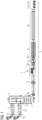
- the combined casting and rolling plant comprises two continuous casting plants 1a and 1b (of course, more than two continuous casting plants are also possible), which are connected to a rolling plant 5 via a slab manipulator 3 and a walking beam furnace 4.
- Liquid steel is cast into slabs 2 on each continuous casting plant 1a, 1b.
- the continuous casting plants each comprise a mold, an arcuate strand guide and a horizontal outlet area which is enclosed in thermal insulation 13.
- the slab strands of the continuous casting plants 1a and 1b are cut by shearing into slabs with a length of between 11.5 and 26 m, normally around 14 m.
- the produced slabs 2 are transported horizontally by the slab manipulator 3 into the gas-fired walking beam furnace 4, where they are heated to rolling temperature and transported to the rolling mill 5.
- the slab 2 is first descaled by a first descaling device 12a and then rolled into a pre-strip by a single-stand, reversing pre-rolling mill 6 through 3 to 5 rolling passes.
- the pre-strip is then wound up into a reel in the preferably thermally insulated coil box 7. After the coil box has been swiveled by 180°, the reel is unwound again and fed to the joining device 8.
- the pre-strips are partially descaled by a second descaling device 12b.
- a foot of a leading pre-strip is connected to the head of a trailing pre-strip to form an endless pre-strip (see also the Fig 3 ).
- the endless preliminary strip is then descaled by a third descaling device 12c and finish-rolled in the five-stand finishing mill to a finished strip with a final thickness of 0.8 mm.
- the finished strip is then cooled in the cooling section 10, cut by high-speed shears (or flying shears) and wound up by several - here, for example, three - coiling devices 11a... 11c.
- the pre-strip or the coiled pre-strip are thermally insulated.
- ⁇ 1a, 1b several continuous casting plants (here 1a, 1b) generate the necessary mass flow of 3.5 to 5.5 M t/a.
- the discrete slabs are heated to rolling temperature via the slab manipulator and the walking beam furnace and fed to the rolling plant 5.
- a slab 2 is first pre-rolled into a reel of a pre-strip.
- the reel is then unwound again and the head of the trailing, i.e. unwound, pre-strip is connected to the foot of a leading pre-strip to form an endless pre-strip.
- the connection is made by joining, specifically by pressing the pre-strips together without welding them together using a welding filler.
- the endless pre-strip is finish-rolled in the finishing mill in continuous operation, which means that ultra-thin hot strips with a thickness of ⁇ 1.2 mm, preferably even ⁇ 1.0 mm, can be easily produced.
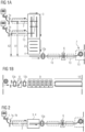
- the Fig 2 shows an elevation view of the casting-rolling composite plant from Fig 1 . It can be seen that the horizontal outlet areas of the two continuous casting plants 1a and 1b are approximately at the same height in the vertical direction as the inlet area of the rolling mill 5. However, no continuous casting plant is connected in-line to the rolling mill 5, since the slabs 2 are first brought into the rolling mill via the slab manipulator 3 and then the walking beam furnace 4. This ensures that the slabs have a constant temperature, regardless of whether they were produced in the first or second continuous casting plant 1a, 1b or even introduced externally into the slab manipulator. Specifically, the outlet area of the first continuous casting plant 1a has a larger offset A1 in the horizontal direction to the rolling mill 5 than the offset A2 in the horizontal direction between the outlet area of the second continuous casting plant 1b and the rolling mill 5.
- Fig 3 the steps in joining two pre-strips 20, 21 to form an endless pre-strip are shown.
- the head of the trailing pre-strip 21 is superimposed on the foot of the leading pre-strip 20, so that an overlapping area 23 is created.
- the pre-strips 20, 21 are then pressed together by pressing and piece forces 24, 25, with cutting edges 22 acting on the underside of the leading pre-strip 20 and the top side of the trailing pre-strip 21.
- pressing together and cutting off the pre-strips 20, 21 an endless pre-strip is created in the central area and two sections 26 above and below the central area.
- the sections are removed either mechanically or by fluid jets of the second descaling device 12b and finish rolled.
Landscapes
- Chemical & Material Sciences (AREA)
- Engineering & Computer Science (AREA)
- Mechanical Engineering (AREA)
- Physics & Mathematics (AREA)
- Thermal Sciences (AREA)
- Crystallography & Structural Chemistry (AREA)
- Materials Engineering (AREA)
- Metallurgy (AREA)
- Organic Chemistry (AREA)
- Metal Rolling (AREA)
Claims (15)
- Installation mixte de coulée et de laminage pour la fabrication d'un feuillard à chaud avec une épaisseur finale < 1,2 mm, de préférence ≤ 1,0 mm, comprenant- au moins une première installation de coulée continue (1a) et une deuxième installation de coulée continue (1b), dans laquelle chaque installation de coulée continue (1a, 1b) coule de l'acier liquide en brames (2) ;- un manipulateur de brames (3) pour le transport des brames (2) depuis les installations de coulée continue (1a, 1b) dans un four à longerons mobiles (4)pour le transport des brames (2) depuis le manipulateur de brames (3) dans une installation de laminage (5) et pour le chauffage des brames (2) à la température de laminage, dans laquelle des brames (2) provenant de la première installation de coulée continue (1a) et des brames (2) provenant de la deuxième installation de coulée continue (1b) traversent complètement le four à longerons mobiles (4) et sont ainsi chauffées uniformément ;- l'installation de laminage (5), comportant-- un laminoir dégrossisseur (6) pour le prélaminage des brames (2) chauffées en un préfeuillard,-- une cage bobineuse (7), de préférence thermiquement isolée, pour l'enroulage du préfeuillard en une bobine et pour le déroulage du préfeuillard,-- un dispositif d'assemblage (8) pour la liaison sans matière additive de soudage d'un pied d'un préfeuillard avant (20) à une tête d'un préfeuillard arrière (21) en un préfeuillard sans fin,-- un laminoir de finition (9) à plusieurs cages pour le laminage de finition du préfeuillard sans fin en un feuillard fini avec l'épaisseur finale,-- une ligne de refroidissement (10) pour le refroidissement du feuillard fini en le feuillard à chaud, et-- plusieurs dispositifs de bobinage (11a ... 11c) pour le bobinage du feuillard à chaud, dans laquelle le laminoir dégrossisseur (6), la cage bobineuse (7), le dispositif d'assemblage (8), le laminoir de finition (9) à plusieurs cages, la ligne de refroidissement (10) et les dispositifs de bobinage (11a ... 11c) de l'installation de laminage (5) sont disposés en ligne les uns derrière les autres et la première installation de coulée continue (1a) présente un premier décalage (A1) dans une première direction par rapport à l'installation de laminage (5) et la deuxième installation de coulée continue (1b) présente un deuxième décalage (A2) dans la première direction par rapport à l'installation de laminage (5).
- Installation mixte de coulée et de laminage selon la revendication 1, caractérisée en ce que les installations de coulée continue (1a, 1b) sont configurées pour la création de brames avec une épaisseur allant de 140 à 240 mm et une largeur comprise entre 1 100 et 2 300 mm.
- Installation mixte de coulée et de laminage selon l'une des revendications précédentes, caractérisée en ce que le laminoir dégrossisseur (6) est un laminoir dégrossisseur réversible, de préférence à une cage.
- Installation mixte de coulée et de laminage selon l'une des revendications précédentes, caractérisée en ce que la première direction est l'horizontale.
- Installation mixte de coulée et de laminage selon l'une des revendications précédentes, caractérisée en ce que le laminoir de finition (9) comprend de cinq à sept cages de laminoir de finition.
- Installation mixte de coulée et de laminage selon l'une des revendications précédentes, caractérisée en ce qu'un premier dispositif de décalaminage (12a) est disposé après le four à longerons mobiles (4) et avant le laminoir dégrossisseur (6) et/ou en ce qu'un deuxième dispositif de décalaminage (12b) est disposé avant le dispositif d'assemblage (8) et un troisième dispositif de décalaminage (12c) est disposé avant le laminoir de finition (9).
- Installation mixte de coulée et de laminage selon l'une des revendications précédentes, caractérisée en ce que le manipulateur de brames (3) peut évacuer des brames (2) créées par les installations de coulée continue (1a, 1b) perpendiculairement à la direction de transport depuis les installations de coulée continue (1a, 1b) jusqu'au four à longerons mobiles (4) et le manipulateur de brames (3) peut faire entrer des brames (2) qui n'ont pas été créées dans les installations de coulée continue (1a, 1b) de l'installation mixte de coulée et de laminage perpendiculairement à la direction de transport depuis les installations de coulée continue (1a, 1b) jusqu'au four à longerons mobiles (4).
- Procédé pour la fabrication d'un feuillard à chaud avec une épaisseur finale < 1,2 mm, de préférence ≤ 1,0 mm, sur une installation mixte de coulée et de laminage, en particulier selon l'une des revendications précédentes, comprenant les étapes suivantes :- coulée continue d'acier liquide en brames (2) sur au moins une première installation de coulée continue (1a) et une deuxième installation de coulée continue (1b) ;- transport des brames (2) depuis les installations de coulée continue (1a, 1b) dans une zone d'entrée d'un four à longerons mobiles (4) ;- transport des brames (2) depuis la zone d'entrée à travers le four à longerons mobiles (4) dans une zone de sortie du four à longerons mobiles (4), dans lequel les brames (2) sont chauffées à la température de laminage ;- prélaminage des brames (2) chauffées en un préfeuillard ;- enroulage du préfeuillard en une bobine et de préférence isolation thermique, de manière particulièrement préférée chauffage, de la bobine ;- déroulage du préfeuillard depuis la bobine ;- liaison sans matière additive de soudage d'un pied d'un préfeuillard avant (20) à une tête d'un préfeuillard arrière (21) en un préfeuillard sans fin ;- laminage de finition du préfeuillard sans fin en un feuillard fini avec l'épaisseur finale par le biais de plusieurs passes de laminage dans un laminoir de finition (9) à plusieurs cages ;- refroidissement du feuillard fini en le feuillard à chaud ;- découpe du feuillard à chaud ; et- bobinage du feuillard à chaud.
- Procédé selon la revendication 8, caractérisé en ce que le prélaminage s'effectue par le biais de plusieurs, de préférence de 3 à 5, passes de laminage dans un laminoir dégrossisseur (6) réversible.
- Procédé selon l'une des revendications 8 à 9, caractérisé en ce que, lors de la liaison des préfeuillards en le préfeuillard sans fin, le pied du préfeuillard avant (20) est d'abord chevauché par une tête du préfeuillard arrière (21), et la zone de chevauchement des préfeuillards (20, 21) est ensuite compressée, dans lequel les positions verticales des préfeuillards (20, 21) sont harmonisées l'une avec l'autre.
- Procédé selon l'une des revendications 8 à 10, caractérisé en ce que les préfeuillards (20, 21) sont décalaminés après le déroulage et avant la liaison.
- Procédé selon l'une des revendications 8 à 11, caractérisé en ce que les brames (2) présentent une épaisseur allant de 140 à 240 mm et une largeur comprise entre 1 100 et 2 300 mm et/ou le préfeuillard présente une épaisseur comprise entre 25 et 35 mm.
- Procédé selon l'une des revendications 8 à 12, caractérisé en ce que les brames (2) sont introduites dans le four à longerons mobiles (4) avec une température ≥ 900 °C.
- Procédé selon l'une des revendications 8 à 13, caractérisé en ce que l'installation mixte de coulée et de laminage présente une capacité de production annuelle comprise entre 3 et 6 millions de tonnes, en particulier comprise entre 3,5 et 5,5 millions de tonnes.
- Procédé selon l'une des revendications 8 à 14, caractérisé en ce que les installations de coulée continue (1a, 1b) produisent des brames (2) avec une épaisseur allant de 150 à 190 mm à une vitesse de coulée allant de 4 à 5 m/min et des brames (2) avec une épaisseur allant de 191 à 230 mm à une vitesse de coulée allant de 2 à 4 m/min.
Applications Claiming Priority (2)
| Application Number | Priority Date | Filing Date | Title |
|---|---|---|---|
| EP21159381.9A EP4049768A1 (fr) | 2021-02-25 | 2021-02-25 | Installation combinée de coulée et de laminage et procédé de fabrication de feuillard d'une épaisseur finale inférieure à 1,2 mm sur l'installation combinée de coulée et de laminage |
| PCT/EP2022/053671 WO2022179890A1 (fr) | 2021-02-25 | 2022-02-15 | Installation intégrée de coulée-laminage et procédé de fabrication d'une bande chaude ayant une épaisseur finale < 1,2 mm sur l'installation intégrée de coulée-laminage |
Publications (3)
| Publication Number | Publication Date |
|---|---|
| EP4297918A1 EP4297918A1 (fr) | 2024-01-03 |
| EP4297918B1 true EP4297918B1 (fr) | 2025-01-29 |
| EP4297918C0 EP4297918C0 (fr) | 2025-01-29 |
Family
ID=74758699
Family Applications (2)
| Application Number | Title | Priority Date | Filing Date |
|---|---|---|---|
| EP21159381.9A Withdrawn EP4049768A1 (fr) | 2021-02-25 | 2021-02-25 | Installation combinée de coulée et de laminage et procédé de fabrication de feuillard d'une épaisseur finale inférieure à 1,2 mm sur l'installation combinée de coulée et de laminage |
| EP22708862.2A Active EP4297918B1 (fr) | 2021-02-25 | 2022-02-15 | Installation combinée de coulée et de laminage et procédé de fabrication de feuillard à chaud d'une épaisseur finale inférieure à 1,2 mm sur l'installation combinée de coulée et de laminage |
Family Applications Before (1)
| Application Number | Title | Priority Date | Filing Date |
|---|---|---|---|
| EP21159381.9A Withdrawn EP4049768A1 (fr) | 2021-02-25 | 2021-02-25 | Installation combinée de coulée et de laminage et procédé de fabrication de feuillard d'une épaisseur finale inférieure à 1,2 mm sur l'installation combinée de coulée et de laminage |
Country Status (4)
| Country | Link |
|---|---|
| US (1) | US20240100590A1 (fr) |
| EP (2) | EP4049768A1 (fr) |
| CN (1) | CN116887930A (fr) |
| WO (1) | WO2022179890A1 (fr) |
Families Citing this family (4)
| Publication number | Priority date | Publication date | Assignee | Title |
|---|---|---|---|---|
| DE102023135962A1 (de) * | 2023-08-28 | 2025-03-06 | Sms Group Gmbh | Warmwalzvorrichtung und Verfahren zum Warmwalzen sowie Anlage zur Herstellung und/oder Verarbeitung eines metallischen Gutes |
| CN117324376A (zh) * | 2023-10-24 | 2024-01-02 | 甘肃酒钢集团宏兴钢铁股份有限公司 | 一种适用于板带轧机生产高锰无磁钢的方法 |
| WO2025131410A1 (fr) * | 2023-12-20 | 2025-06-26 | Sms Group Gmbh | Dispositif de laminage à chaud, procédé de laminage à chaud et installation pour la production et/ou le traitement d'une pièce métallique |
| WO2025131409A1 (fr) * | 2023-12-20 | 2025-06-26 | Sms Group Gmbh | Installation de coulée et de laminage combinée pour la mise en forme primaire d'un matériau de laminage métallique et le laminage à chaud d'une bande de matériau, et procédé pour la mise en forme primaire d'un matériau de laminage métallique et pour le laminage à chaud direct |
Citations (3)
| Publication number | Priority date | Publication date | Assignee | Title |
|---|---|---|---|---|
| DE4041206C2 (de) * | 1990-12-21 | 2003-04-17 | Sms Demag Ag | Verfahren und Anlage zur Herstellung von warmgewalztem Stahlband, insbesondere für Edelstähle aus stranggegossenem Vormaterial |
| DE102015216512A1 (de) * | 2015-08-28 | 2017-03-02 | Sms Group Gmbh | Anlage nach dem CSP-Konzept sowie Verfahren zum Betreiben einer solchen Anlage |
| DE102019207459A1 (de) * | 2018-05-23 | 2019-11-28 | Sms Group Gmbh | Gieß-Walzanlage für den Batch- und Endlosbetrieb |
Family Cites Families (6)
| Publication number | Priority date | Publication date | Assignee | Title |
|---|---|---|---|---|
| IT1259487B (it) * | 1992-08-26 | 1996-03-20 | Danieli Off Mecc | Procedimento per la produzione di lamiere sottili ed impianto di laminazione compatto adottante tale procedimento |
| DE19732538A1 (de) * | 1997-07-23 | 1999-01-28 | Mannesmann Ag | Warmbandstraße für 0,5 mm dickes Warmband |
| JP4698132B2 (ja) * | 2003-07-31 | 2011-06-08 | 三菱日立製鉄機械株式会社 | 熱間圧延設備 |
| CN1883835A (zh) * | 2005-06-20 | 2006-12-27 | 中冶东方工程技术有限公司 | 常规板坯连铸连轧板卷的生产方法 |
| WO2009003342A1 (fr) * | 2007-07-04 | 2009-01-08 | Baoshan Iron & Steel Co., Ltd. | Procédé à économie d'énergie et très efficace pour couler-laminer en continu des bandes d'acier |
| DE102011008434A1 (de) * | 2011-01-12 | 2012-07-12 | Sms Siemag Ag | Anlage und Verfahren zum Erzeugen von Warmband |
-
2021
- 2021-02-25 EP EP21159381.9A patent/EP4049768A1/fr not_active Withdrawn
-
2022
- 2022-02-15 WO PCT/EP2022/053671 patent/WO2022179890A1/fr not_active Ceased
- 2022-02-15 CN CN202280017270.6A patent/CN116887930A/zh active Pending
- 2022-02-15 EP EP22708862.2A patent/EP4297918B1/fr active Active
- 2022-02-15 US US18/264,342 patent/US20240100590A1/en active Pending
Patent Citations (3)
| Publication number | Priority date | Publication date | Assignee | Title |
|---|---|---|---|---|
| DE4041206C2 (de) * | 1990-12-21 | 2003-04-17 | Sms Demag Ag | Verfahren und Anlage zur Herstellung von warmgewalztem Stahlband, insbesondere für Edelstähle aus stranggegossenem Vormaterial |
| DE102015216512A1 (de) * | 2015-08-28 | 2017-03-02 | Sms Group Gmbh | Anlage nach dem CSP-Konzept sowie Verfahren zum Betreiben einer solchen Anlage |
| DE102019207459A1 (de) * | 2018-05-23 | 2019-11-28 | Sms Group Gmbh | Gieß-Walzanlage für den Batch- und Endlosbetrieb |
Also Published As
| Publication number | Publication date |
|---|---|
| EP4297918A1 (fr) | 2024-01-03 |
| US20240100590A1 (en) | 2024-03-28 |
| CN116887930A (zh) | 2023-10-13 |
| WO2022179890A1 (fr) | 2022-09-01 |
| EP4049768A1 (fr) | 2022-08-31 |
| EP4297918C0 (fr) | 2025-01-29 |
Similar Documents
| Publication | Publication Date | Title |
|---|---|---|
| DE69316703T2 (de) | Verfahren und anlage zum stranggiessen von brammen mittlerer dicke und zum unmittelbar nachfolgenden herstellen von warmbändern und -blechen | |
| EP1960131B1 (fr) | Procede et dispositif pour produire des bandes metalliques par coulee continue et laminage | |
| EP3504013B2 (fr) | Procédé de fabrication d'une bande métallique dans une installation de laminage direct | |
| EP3535076B1 (fr) | Installation mixte de coulée-laminage et procédé de fabrication continue d'une bande finie laminée à chaud | |
| EP1047510B1 (fr) | Procede et installation de production continue de produits plats et minces lamines a chaud | |
| EP2627464B1 (fr) | Procédé et installation de production à efficacité énergétique pour une bande d'acier laminée à chaud | |
| EP1951451B2 (fr) | Procede de fabrication d'un feuillard d'acier lamine a chaud et installation combinee de coulee et de laminage en vue de la mise en oeuvre du procede | |
| EP2964404B1 (fr) | Procédé de production d'une bande métallique au moyen de cylindres de coulée | |
| EP4297918A1 (fr) | Installation intégrée de coulée-laminage et procédé de fabrication d'une bande chaude ayant une épaisseur finale <1,2 mm sur l'installation intégrée de coulée-laminage | |
| EP3558563B1 (fr) | Procede de fabrication de bandes bobinees sans fin laminees a chaud dans une installation combinee de coulee et de laminage, et installation combinee de coulee et de laminage | |
| EP1305122A1 (fr) | Procede et installation de fabrication de produits plats minces | |
| EP3797006B1 (fr) | Installation de coulée et de laminage destinée au fonctionnement par lots et continu | |
| DE10304318B4 (de) | Verfahren zum Walzen von dünnen und/oder dicken Brammen aus Stahlwerkstoffen zu Warmband | |
| EP2441539A1 (fr) | Procédé à sortie d'énergie optimisée et installation de production d'une bande chaude en acier | |
| EP1113888B1 (fr) | Procede et installation de production d'une bande d'acier laminee a chaud a partir d'une masse d'acier en fusion | |
| DE4041206C2 (de) | Verfahren und Anlage zur Herstellung von warmgewalztem Stahlband, insbesondere für Edelstähle aus stranggegossenem Vormaterial | |
| WO2016165933A1 (fr) | Installation de coulée et de laminage et procédé servant à faire fonctionner ladite installation | |
| EP3027331B1 (fr) | Installation de laminage de coulée continue et procédé de fabrication de brames | |
| EP0734793A1 (fr) | Procédé et dispositif pour la production de bandes d'acier laminées à chaud | |
| EP1641573B1 (fr) | Dispositif pour la production de feuillard d'acier lamine a chaud, en particulier a partir d'ebauche en bande coulee en continu | |
| EP4537950A1 (fr) | Installation et procédé de fabrication d'une bande métallique en fonctionnement continu ou en mode discontinu | |
| DE19732538A1 (de) | Warmbandstraße für 0,5 mm dickes Warmband |
Legal Events
| Date | Code | Title | Description |
|---|---|---|---|
| STAA | Information on the status of an ep patent application or granted ep patent |
Free format text: STATUS: UNKNOWN |
|
| STAA | Information on the status of an ep patent application or granted ep patent |
Free format text: STATUS: THE INTERNATIONAL PUBLICATION HAS BEEN MADE |
|
| PUAI | Public reference made under article 153(3) epc to a published international application that has entered the european phase |
Free format text: ORIGINAL CODE: 0009012 |
|
| STAA | Information on the status of an ep patent application or granted ep patent |
Free format text: STATUS: REQUEST FOR EXAMINATION WAS MADE |
|
| 17P | Request for examination filed |
Effective date: 20230925 |
|
| AK | Designated contracting states |
Kind code of ref document: A1 Designated state(s): AL AT BE BG CH CY CZ DE DK EE ES FI FR GB GR HR HU IE IS IT LI LT LU LV MC MK MT NL NO PL PT RO RS SE SI SK SM TR |
|
| DAV | Request for validation of the european patent (deleted) | ||
| DAX | Request for extension of the european patent (deleted) | ||
| GRAP | Despatch of communication of intention to grant a patent |
Free format text: ORIGINAL CODE: EPIDOSNIGR1 |
|
| STAA | Information on the status of an ep patent application or granted ep patent |
Free format text: STATUS: GRANT OF PATENT IS INTENDED |
|
| INTG | Intention to grant announced |
Effective date: 20241016 |
|
| GRAS | Grant fee paid |
Free format text: ORIGINAL CODE: EPIDOSNIGR3 |
|
| GRAA | (expected) grant |
Free format text: ORIGINAL CODE: 0009210 |
|
| STAA | Information on the status of an ep patent application or granted ep patent |
Free format text: STATUS: THE PATENT HAS BEEN GRANTED |
|
| AK | Designated contracting states |
Kind code of ref document: B1 Designated state(s): AL AT BE BG CH CY CZ DE DK EE ES FI FR GB GR HR HU IE IS IT LI LT LU LV MC MK MT NL NO PL PT RO RS SE SI SK SM TR |
|
| REG | Reference to a national code |
Ref country code: GB Ref legal event code: FG4D Free format text: NOT ENGLISH |
|
| REG | Reference to a national code |
Ref country code: CH Ref legal event code: EP |
|
| REG | Reference to a national code |
Ref country code: DE Ref legal event code: R096 Ref document number: 502022002795 Country of ref document: DE |
|
| REG | Reference to a national code |
Ref country code: IE Ref legal event code: FG4D Free format text: LANGUAGE OF EP DOCUMENT: GERMAN |
|
| U01 | Request for unitary effect filed |
Effective date: 20250129 |
|
| U07 | Unitary effect registered |
Designated state(s): AT BE BG DE DK EE FI FR IT LT LU LV MT NL PT RO SE SI Effective date: 20250204 |
|
| U20 | Renewal fee for the european patent with unitary effect paid |
Year of fee payment: 4 Effective date: 20250506 |
|
| PG25 | Lapsed in a contracting state [announced via postgrant information from national office to epo] |
Ref country code: RS Free format text: LAPSE BECAUSE OF FAILURE TO SUBMIT A TRANSLATION OF THE DESCRIPTION OR TO PAY THE FEE WITHIN THE PRESCRIBED TIME-LIMIT Effective date: 20250429 |
|
| PG25 | Lapsed in a contracting state [announced via postgrant information from national office to epo] |
Ref country code: PL Free format text: LAPSE BECAUSE OF FAILURE TO SUBMIT A TRANSLATION OF THE DESCRIPTION OR TO PAY THE FEE WITHIN THE PRESCRIBED TIME-LIMIT Effective date: 20250129 |
|
| PG25 | Lapsed in a contracting state [announced via postgrant information from national office to epo] |
Ref country code: ES Free format text: LAPSE BECAUSE OF FAILURE TO SUBMIT A TRANSLATION OF THE DESCRIPTION OR TO PAY THE FEE WITHIN THE PRESCRIBED TIME-LIMIT Effective date: 20250129 |
|
| PG25 | Lapsed in a contracting state [announced via postgrant information from national office to epo] |
Ref country code: IS Free format text: LAPSE BECAUSE OF FAILURE TO SUBMIT A TRANSLATION OF THE DESCRIPTION OR TO PAY THE FEE WITHIN THE PRESCRIBED TIME-LIMIT Effective date: 20250529 Ref country code: NO Free format text: LAPSE BECAUSE OF FAILURE TO SUBMIT A TRANSLATION OF THE DESCRIPTION OR TO PAY THE FEE WITHIN THE PRESCRIBED TIME-LIMIT Effective date: 20250429 |
|
| PG25 | Lapsed in a contracting state [announced via postgrant information from national office to epo] |
Ref country code: HR Free format text: LAPSE BECAUSE OF FAILURE TO SUBMIT A TRANSLATION OF THE DESCRIPTION OR TO PAY THE FEE WITHIN THE PRESCRIBED TIME-LIMIT Effective date: 20250129 |
|
| PG25 | Lapsed in a contracting state [announced via postgrant information from national office to epo] |
Ref country code: GR Free format text: LAPSE BECAUSE OF FAILURE TO SUBMIT A TRANSLATION OF THE DESCRIPTION OR TO PAY THE FEE WITHIN THE PRESCRIBED TIME-LIMIT Effective date: 20250430 |
|
| REG | Reference to a national code |
Ref country code: CH Ref legal event code: PL |
|
| PG25 | Lapsed in a contracting state [announced via postgrant information from national office to epo] |
Ref country code: SM Free format text: LAPSE BECAUSE OF FAILURE TO SUBMIT A TRANSLATION OF THE DESCRIPTION OR TO PAY THE FEE WITHIN THE PRESCRIBED TIME-LIMIT Effective date: 20250129 |
|
| PG25 | Lapsed in a contracting state [announced via postgrant information from national office to epo] |
Ref country code: MC Free format text: LAPSE BECAUSE OF FAILURE TO SUBMIT A TRANSLATION OF THE DESCRIPTION OR TO PAY THE FEE WITHIN THE PRESCRIBED TIME-LIMIT Effective date: 20250129 |
|
| PG25 | Lapsed in a contracting state [announced via postgrant information from national office to epo] |
Ref country code: CH Free format text: LAPSE BECAUSE OF NON-PAYMENT OF DUE FEES Effective date: 20250228 |
|
| PG25 | Lapsed in a contracting state [announced via postgrant information from national office to epo] |
Ref country code: CZ Free format text: LAPSE BECAUSE OF FAILURE TO SUBMIT A TRANSLATION OF THE DESCRIPTION OR TO PAY THE FEE WITHIN THE PRESCRIBED TIME-LIMIT Effective date: 20250129 |
|
| PG25 | Lapsed in a contracting state [announced via postgrant information from national office to epo] |
Ref country code: SK Free format text: LAPSE BECAUSE OF FAILURE TO SUBMIT A TRANSLATION OF THE DESCRIPTION OR TO PAY THE FEE WITHIN THE PRESCRIBED TIME-LIMIT Effective date: 20250129 |
|
| PLBE | No opposition filed within time limit |
Free format text: ORIGINAL CODE: 0009261 |
|
| STAA | Information on the status of an ep patent application or granted ep patent |
Free format text: STATUS: NO OPPOSITION FILED WITHIN TIME LIMIT |
|
| 26N | No opposition filed |
Effective date: 20251030 |
|
| PG25 | Lapsed in a contracting state [announced via postgrant information from national office to epo] |
Ref country code: IE Free format text: LAPSE BECAUSE OF NON-PAYMENT OF DUE FEES Effective date: 20250215 |
|
| U20 | Renewal fee for the european patent with unitary effect paid |
Year of fee payment: 5 Effective date: 20260302 |
|
| PGFP | Annual fee paid to national office [announced via postgrant information from national office to epo] |
Ref country code: TR Payment date: 20260210 Year of fee payment: 5 |