EP4292883B1 - Scheinwerfer für fahrzeuge - Google Patents
Scheinwerfer für fahrzeuge Download PDFInfo
- Publication number
- EP4292883B1 EP4292883B1 EP22752687.8A EP22752687A EP4292883B1 EP 4292883 B1 EP4292883 B1 EP 4292883B1 EP 22752687 A EP22752687 A EP 22752687A EP 4292883 B1 EP4292883 B1 EP 4292883B1
- Authority
- EP
- European Patent Office
- Prior art keywords
- region
- vehicle
- light
- ego
- light source
- Prior art date
- Legal status (The legal status is an assumption and is not a legal conclusion. Google has not performed a legal analysis and makes no representation as to the accuracy of the status listed.)
- Active
Links
Images


Classifications
-
- B—PERFORMING OPERATIONS; TRANSPORTING
- B60—VEHICLES IN GENERAL
- B60Q—ARRANGEMENT OF SIGNALLING OR LIGHTING DEVICES, THE MOUNTING OR SUPPORTING THEREOF OR CIRCUITS THEREFOR, FOR VEHICLES IN GENERAL
- B60Q1/00—Arrangement of optical signalling or lighting devices, the mounting or supporting thereof or circuits therefor
- B60Q1/02—Arrangement of optical signalling or lighting devices, the mounting or supporting thereof or circuits therefor the devices being primarily intended to illuminate the way ahead or to illuminate other areas of way or environments
- B60Q1/04—Arrangement of optical signalling or lighting devices, the mounting or supporting thereof or circuits therefor the devices being primarily intended to illuminate the way ahead or to illuminate other areas of way or environments the devices being headlights
- B60Q1/06—Arrangement of optical signalling or lighting devices, the mounting or supporting thereof or circuits therefor the devices being primarily intended to illuminate the way ahead or to illuminate other areas of way or environments the devices being headlights adjustable, e.g. remotely-controlled from inside vehicle
- B60Q1/08—Arrangement of optical signalling or lighting devices, the mounting or supporting thereof or circuits therefor the devices being primarily intended to illuminate the way ahead or to illuminate other areas of way or environments the devices being headlights adjustable, e.g. remotely-controlled from inside vehicle automatically
- B60Q1/10—Arrangement of optical signalling or lighting devices, the mounting or supporting thereof or circuits therefor the devices being primarily intended to illuminate the way ahead or to illuminate other areas of way or environments the devices being headlights adjustable, e.g. remotely-controlled from inside vehicle automatically due to vehicle inclination, e.g. due to load distribution
-
- B—PERFORMING OPERATIONS; TRANSPORTING
- B60—VEHICLES IN GENERAL
- B60Q—ARRANGEMENT OF SIGNALLING OR LIGHTING DEVICES, THE MOUNTING OR SUPPORTING THEREOF OR CIRCUITS THEREFOR, FOR VEHICLES IN GENERAL
- B60Q1/00—Arrangement of optical signalling or lighting devices, the mounting or supporting thereof or circuits therefor
- B60Q1/02—Arrangement of optical signalling or lighting devices, the mounting or supporting thereof or circuits therefor the devices being primarily intended to illuminate the way ahead or to illuminate other areas of way or environments
- B60Q1/04—Arrangement of optical signalling or lighting devices, the mounting or supporting thereof or circuits therefor the devices being primarily intended to illuminate the way ahead or to illuminate other areas of way or environments the devices being headlights
- B60Q1/14—Arrangement of optical signalling or lighting devices, the mounting or supporting thereof or circuits therefor the devices being primarily intended to illuminate the way ahead or to illuminate other areas of way or environments the devices being headlights having dimming means
- B60Q1/1415—Dimming circuits
- B60Q1/1423—Automatic dimming circuits, i.e. switching between high beam and low beam due to change of ambient light or light level in road traffic
- B60Q1/143—Automatic dimming circuits, i.e. switching between high beam and low beam due to change of ambient light or light level in road traffic combined with another condition, e.g. using vehicle recognition from camera images or activation of wipers
-
- F—MECHANICAL ENGINEERING; LIGHTING; HEATING; WEAPONS; BLASTING
- F21—LIGHTING
- F21S—NON-PORTABLE LIGHTING DEVICES; SYSTEMS THEREOF; VEHICLE LIGHTING DEVICES SPECIALLY ADAPTED FOR VEHICLE EXTERIORS
- F21S41/00—Illuminating devices specially adapted for vehicle exteriors, e.g. headlamps
- F21S41/10—Illuminating devices specially adapted for vehicle exteriors, e.g. headlamps characterised by the light source
- F21S41/14—Illuminating devices specially adapted for vehicle exteriors, e.g. headlamps characterised by the light source characterised by the type of light source
- F21S41/141—Light emitting diodes [LED]
- F21S41/143—Light emitting diodes [LED] the main emission direction of the LED being parallel to the optical axis of the illuminating device
-
- F—MECHANICAL ENGINEERING; LIGHTING; HEATING; WEAPONS; BLASTING
- F21—LIGHTING
- F21S—NON-PORTABLE LIGHTING DEVICES; SYSTEMS THEREOF; VEHICLE LIGHTING DEVICES SPECIALLY ADAPTED FOR VEHICLE EXTERIORS
- F21S41/00—Illuminating devices specially adapted for vehicle exteriors, e.g. headlamps
- F21S41/10—Illuminating devices specially adapted for vehicle exteriors, e.g. headlamps characterised by the light source
- F21S41/14—Illuminating devices specially adapted for vehicle exteriors, e.g. headlamps characterised by the light source characterised by the type of light source
- F21S41/141—Light emitting diodes [LED]
- F21S41/151—Light emitting diodes [LED] arranged in one or more lines
- F21S41/153—Light emitting diodes [LED] arranged in one or more lines arranged in a matrix
-
- F—MECHANICAL ENGINEERING; LIGHTING; HEATING; WEAPONS; BLASTING
- F21—LIGHTING
- F21S—NON-PORTABLE LIGHTING DEVICES; SYSTEMS THEREOF; VEHICLE LIGHTING DEVICES SPECIALLY ADAPTED FOR VEHICLE EXTERIORS
- F21S41/00—Illuminating devices specially adapted for vehicle exteriors, e.g. headlamps
- F21S41/60—Illuminating devices specially adapted for vehicle exteriors, e.g. headlamps characterised by a variable light distribution
- F21S41/65—Illuminating devices specially adapted for vehicle exteriors, e.g. headlamps characterised by a variable light distribution by acting on light sources
- F21S41/663—Illuminating devices specially adapted for vehicle exteriors, e.g. headlamps characterised by a variable light distribution by acting on light sources by switching light sources
-
- F—MECHANICAL ENGINEERING; LIGHTING; HEATING; WEAPONS; BLASTING
- F21—LIGHTING
- F21V—FUNCTIONAL FEATURES OR DETAILS OF LIGHTING DEVICES OR SYSTEMS THEREOF; STRUCTURAL COMBINATIONS OF LIGHTING DEVICES WITH OTHER ARTICLES, NOT OTHERWISE PROVIDED FOR
- F21V14/00—Controlling the distribution of the light emitted by adjustment of elements
- F21V14/04—Controlling the distribution of the light emitted by adjustment of elements by movement of reflectors
-
- F—MECHANICAL ENGINEERING; LIGHTING; HEATING; WEAPONS; BLASTING
- F21—LIGHTING
- F21V—FUNCTIONAL FEATURES OR DETAILS OF LIGHTING DEVICES OR SYSTEMS THEREOF; STRUCTURAL COMBINATIONS OF LIGHTING DEVICES WITH OTHER ARTICLES, NOT OTHERWISE PROVIDED FOR
- F21V7/00—Reflectors for light sources
-
- F—MECHANICAL ENGINEERING; LIGHTING; HEATING; WEAPONS; BLASTING
- F21—LIGHTING
- F21V—FUNCTIONAL FEATURES OR DETAILS OF LIGHTING DEVICES OR SYSTEMS THEREOF; STRUCTURAL COMBINATIONS OF LIGHTING DEVICES WITH OTHER ARTICLES, NOT OTHERWISE PROVIDED FOR
- F21V9/00—Elements for modifying spectral properties, polarisation or intensity of the light emitted, e.g. filters
- F21V9/40—Elements for modifying spectral properties, polarisation or intensity of the light emitted, e.g. filters with provision for controlling spectral properties, e.g. colour, or intensity
-
- B—PERFORMING OPERATIONS; TRANSPORTING
- B60—VEHICLES IN GENERAL
- B60Q—ARRANGEMENT OF SIGNALLING OR LIGHTING DEVICES, THE MOUNTING OR SUPPORTING THEREOF OR CIRCUITS THEREFOR, FOR VEHICLES IN GENERAL
- B60Q2300/00—Indexing codes for automatically adjustable headlamps or automatically dimmable headlamps
- B60Q2300/05—Special features for controlling or switching of the light beam
- B60Q2300/056—Special anti-blinding beams, e.g. a standard beam is chopped or moved in order not to blind
-
- B—PERFORMING OPERATIONS; TRANSPORTING
- B60—VEHICLES IN GENERAL
- B60Q—ARRANGEMENT OF SIGNALLING OR LIGHTING DEVICES, THE MOUNTING OR SUPPORTING THEREOF OR CIRCUITS THEREFOR, FOR VEHICLES IN GENERAL
- B60Q2300/00—Indexing codes for automatically adjustable headlamps or automatically dimmable headlamps
- B60Q2300/10—Indexing codes relating to particular vehicle conditions
- B60Q2300/13—Attitude of the vehicle body
- B60Q2300/132—Pitch
-
- B—PERFORMING OPERATIONS; TRANSPORTING
- B60—VEHICLES IN GENERAL
- B60Q—ARRANGEMENT OF SIGNALLING OR LIGHTING DEVICES, THE MOUNTING OR SUPPORTING THEREOF OR CIRCUITS THEREFOR, FOR VEHICLES IN GENERAL
- B60Q2300/00—Indexing codes for automatically adjustable headlamps or automatically dimmable headlamps
- B60Q2300/40—Indexing codes relating to other road users or special conditions
- B60Q2300/41—Indexing codes relating to other road users or special conditions preceding vehicle
-
- B—PERFORMING OPERATIONS; TRANSPORTING
- B60—VEHICLES IN GENERAL
- B60Q—ARRANGEMENT OF SIGNALLING OR LIGHTING DEVICES, THE MOUNTING OR SUPPORTING THEREOF OR CIRCUITS THEREFOR, FOR VEHICLES IN GENERAL
- B60Q2300/00—Indexing codes for automatically adjustable headlamps or automatically dimmable headlamps
- B60Q2300/40—Indexing codes relating to other road users or special conditions
- B60Q2300/42—Indexing codes relating to other road users or special conditions oncoming vehicle
-
- F—MECHANICAL ENGINEERING; LIGHTING; HEATING; WEAPONS; BLASTING
- F21—LIGHTING
- F21W—INDEXING SCHEME ASSOCIATED WITH SUBCLASSES F21K, F21L, F21S and F21V, RELATING TO USES OR APPLICATIONS OF LIGHTING DEVICES OR SYSTEMS
- F21W2102/00—Exterior vehicle lighting devices for illuminating purposes
- F21W2102/10—Arrangement or contour of the emitted light
- F21W2102/13—Arrangement or contour of the emitted light for high-beam region or low-beam region
- F21W2102/135—Arrangement or contour of the emitted light for high-beam region or low-beam region the light having cut-off lines, i.e. clear borderlines between emitted regions and dark regions
- F21W2102/14—Arrangement or contour of the emitted light for high-beam region or low-beam region the light having cut-off lines, i.e. clear borderlines between emitted regions and dark regions having vertical cut-off lines; specially adapted for adaptive high beams, i.e. wherein the beam is broader but avoids glaring other road users
-
- F—MECHANICAL ENGINEERING; LIGHTING; HEATING; WEAPONS; BLASTING
- F21—LIGHTING
- F21W—INDEXING SCHEME ASSOCIATED WITH SUBCLASSES F21K, F21L, F21S and F21V, RELATING TO USES OR APPLICATIONS OF LIGHTING DEVICES OR SYSTEMS
- F21W2102/00—Exterior vehicle lighting devices for illuminating purposes
- F21W2102/10—Arrangement or contour of the emitted light
- F21W2102/17—Arrangement or contour of the emitted light for regions other than high beam or low beam
- F21W2102/19—Arrangement or contour of the emitted light for regions other than high beam or low beam for curves
-
- F—MECHANICAL ENGINEERING; LIGHTING; HEATING; WEAPONS; BLASTING
- F21—LIGHTING
- F21Y—INDEXING SCHEME ASSOCIATED WITH SUBCLASSES F21K, F21L, F21S and F21V, RELATING TO THE FORM OR THE KIND OF THE LIGHT SOURCES OR OF THE COLOUR OF THE LIGHT EMITTED
- F21Y2115/00—Light-generating elements of semiconductor light sources
- F21Y2115/10—Light-emitting diodes [LED]
Definitions
- the present invention relates to vehicle headlights.
- the vehicle headlight disclosed in JP 2020-131922 A is known.
- the vehicle headlight disclosed in JP 2020-131922 A is equipped with an LED array including a plurality of LEDs, and forms a light distribution pattern that can be changed by light beams emitted from the LED array.
- LEDs that irradiate the other vehicle and a surrounding region thereof are turned off to perform so-called ADB (Adaptive Driving Beam) control.
- ADB Adaptive Driving Beam
- WO 2021/018657 A1 discloses a method for controlling a lighting device for a motor vehicle comprising at least first and second light modules (3, 4) arranged to emit, respectively, first and second pixelated light beams (HD, LD) in first and second predetermined emission zones (ZHD, ZLD) which are associated with them, the resolution of the first pixelated light beam being greater than the resolution of the second pixelated light beam and the first and second predetermined emission zones being adjacent.
- EP 2979923 A1 , EP 3671015 A , and JP 2020 055516 A each disclose vehicle lights having specific illumination patterns.
- an object of the present invention is to provide a vehicle headlight capable of suppressing dazzling of another vehicle when performing ADB control.
- a vehicle headlight of the present invention is equipped with: a light source unit for forming a light distribution pattern which can be changed by light beams emitted from a light source group; and a control unit, wherein, in a case where a detection signal of another vehicle present in front of an ego-vehicle is inputted from a detection unit for detecting the other vehicle, the control unit causes first light sources of the light source group, which emit light toward a first region including a region overlapping a visual recognition part of the other vehicle used by a driver thereof to visually recognize the outside of the other vehicle, to emit light having a lower intensity than in a case where no detection signal is inputted, and causes second light sources, among second light sources of the light source group that emit light toward a second region surrounding the first region, which emit light toward a lower-side region lower than the first region, to emit light with an increasingly lower intensity toward the side closer to the first region.
- the visual recognition part is, in a case where the other vehicle is a preceding vehicle, the rear windshield and a door mirror of the preceding vehicle, and is, in a case where the other vehicle is an oncoming vehicle, the front windshield of the oncoming vehicle.
- the first region overlapping the visual recognition part of the other vehicle becomes darker than in the case where no detection signal of the other vehicle is inputted. Therefore, by darkening the first region as described above, it is possible to suppress dazzling of another vehicle when performing ADB control.
- the control unit causes second light sources, which emit light toward a lower-side region of a second region located lower than the first region, to emit light with an increasingly lower intensity toward the side closer to the first region. Therefore, in this vehicle headlight, gradation in which the intensity of light decreases toward the first region is formed in the second region located below the first region. In this way, the lower-side region in the second region becomes darker toward the first region. Therefore, for example, even in a case where the lower-side region of the second region overlaps the visual recognition part of another vehicle due to the ego-vehicle colliding and tilting upward, this gradation is interposed, and therefore the visual recognition part of another vehicle is prevented from being suddenly brightly irradiated. Therefore, with this vehicle headlight, it is possible to suppress dazzling of another vehicle more effectively when performing ADB control.
- the control unit increases the width of the lower-side region in the up-down direction as the tilt of the ego-vehicle increases.
- the lower-side region where the gradation is formed can easily overlap the visual recognition part of the other vehicle. For this reason, it is possible to suppress dazzling of another vehicle more effectively when performing ADB control.
- the control unit preferably causes, among the second light sources, the second light sources which emit light toward an upper-side region above the first region to emit light with an increasingly lower intensity toward the side closer to the first region.
- gradation in which the light intensity decreases toward the first region is formed in the second region located above the first region.
- the upper-side region in the second region becomes darker toward the first region. Therefore, for example, even in a case where the upper-side region of the second region overlaps the visual recognition part of another vehicle due to the ego-vehicle colliding and tilting downward, this gradation is interposed, and therefore the visual recognition part of another vehicle is prevented from being suddenly brightly irradiated.
- control unit may increase the width of the upper-side region in the up-down direction as the tilt of the ego-vehicle increases.
- the upper-side region where the gradation is formed is more likely to overlap the visual recognition part of another vehicle. For this reason, it is possible to suppress dazzling of another vehicle more effectively when performing ADB control.
- the control unit causes at least one second light source of: a second light source that emits light toward a left-side region on a left side of the first region among the second light sources, and a second light source that emits light toward a right-side region on a right side of the first region among the second light sources, to emit light with an increasingly lower intensity toward the side closer to the first region.
- left and right means left and right when the direction of travel of the ego-vehicle is used as a reference, unless otherwise specified.
- gradation in which the light intensity decreases toward the first region is formed in the second region located on the left side of the first region. In this case, the left-side region becomes darker toward the first region. Further, with such a configuration, gradation in which the light intensity decreases toward the first region is formed in the second region located on the right side of the first region. In this case, the right-side region becomes darker toward the first region.
- At least one of a width in the left-right direction of the left-side region and a width in the left-right direction of the right-side region is preferably smaller than a width in the up-down direction of the lower side region.
- the width in the left-right direction of the left-side region and the width in the left-right direction of the right-side region is smaller than the width in the up-down direction of the lower-side region, it is possible to widen the region where gradation is not formed in the second region in comparison with a case where both the width in the left-right direction of the left-side region and the width in the left-right direction of the right-side region are equal to or greater than the width in the up-down direction of the lower-side region.
- the region where the gradation is not formed is located on the side opposite to the first region side of a left-side region and a right-side region, respectively, this region is substantially brighter than the left-side region and the right-side region. Therefore, because the region in which the gradation is not formed in the second region is widened, the front of the ego-vehicle can be brightened, and the visibility when performing ADB control can be improved.
- the width in the left-right direction of the left-side region in a case where the other vehicle is an oncoming vehicle can be increased in comparison with a case where the ratio of the width is equal to or less than the ratio of the left-side region to the first region in a case where the other vehicle is a preceding vehicle. For this reason, even in a case where an oncoming vehicle rapidly approaches the ego-vehicle and where the left-side region of the second region overlaps the visual recognition part of the oncoming vehicle, the visual recognition part of the approaching oncoming vehicle can be prevented from being suddenly brightly irradiated by interposing the left-side region where gradation is formed. Therefore, dazzling of the oncoming vehicle can be effectively suppressed.
- the ratio of the width in the left-right direction of the right-side region to the width in the left-right direction of the first region may be greater than the ratio of the width in the left-right direction of the right-side region to the width in the left-right direction of the first region in a case where the other vehicle is a preceding vehicle.
- the ratio of the width in the left-right direction of the right-side region to the width in the left-right direction of the first region is made greater than the ratio of the width in the left-right direction of the right-side region to the width in the left-right direction of the first region in a case where the other vehicle is a preceding vehicle.
- the width of the right-side region in the left-right direction in a case where the other vehicle is an oncoming vehicle can be increased.
- the visual recognition part of the approaching oncoming vehicle can be prevented from being suddenly brightly irradiated by interposing the right-side region where gradation is formed.
- a width in the left-right direction in a third region which is a region farther from the ego-vehicle in the left-side region and the right-side region in a case where the other vehicle is an oncoming vehicle, may be greater than a width in the left-right direction in a fourth region, which is a region closer to the ego-vehicle in the left-side region and the right-side region in a case where the other vehicle is an oncoming vehicle.
- the width in the left-right direction in the third region is made greater than the width in the left-right direction in the fourth region.
- the visual recognition part of the oncoming vehicle can be prevented from being suddenly brightly irradiated by interposing one of the left-side region and the right-side region where gradation is formed.
- a vehicle headlight that can suppress dazzling of another vehicle when performing ADB control can be provided.
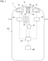
- FIG. 1 is a plan view conceptually illustrating an ego-vehicle 100 that is equipped with a vehicle headlight according to an embodiment.
- the ego-vehicle 100 is equipped with a vehicle headlight system 2, and the vehicle headlight system 2 includes a vehicle headlight 1, a detection device 20, a tilt calculation device 21, and the like.
- the vehicle headlight 1 is mainly equipped with a pair of left and right light source units 10, a control unit CO, a determination unit 25, a pair of power supply circuits 30, and a memory ME.
- the pair of light source units 10 have a substantially symmetrical shape in the left-right direction of the ego-vehicle 100, and emit light of a changeable light distribution pattern toward another vehicle located in front of the ego-vehicle 100. Furthermore, the configuration of one light source unit 10 is the same as the configuration of the other light source unit 10 except that the shape is substantially symmetrical. Therefore, one light source unit 10 will be described below, and a description of the other light source unit 10 will be omitted.
- light distribution pattern means, for example, a shape of an image projected on a surface arranged 25 meters ahead and an intensity distribution of light in the image.
- At least a portion on the front side of the housing 16 has translucency, and the light distribution pattern formation unit 12 and the projection lens 15 are housed in a lamp chamber R formed by the housing 16.
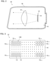
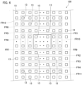
- FIG. 3 is a front view schematically illustrating the light distribution pattern formation unit 12 illustrated in FIG. 2 , as viewed from the front.
- the light distribution pattern formation unit 12 includes a light source group 130 including a plurality of light sources 13 that emit light, and a circuit board 14 whereon the light source group 130 is mounted.
- the circuit board 14 is connected to the power supply circuits 30.
- the plurality of light sources 13 are arranged in a matrix, and each of the light sources 13 emits light forward.
- the light sources 13 are LEDs (Light Emitting Diodes), and the light distribution pattern formation unit 12 is configured as a so-called LED array.
- the plurality of light sources 13 is provided in an arrangement of n rows ⁇ m columns.
- the first column which is the rightmost column in FIG. 3 , is the leftmost column in a case where the direction of travel is used as a reference
- the mth column which is the leftmost column in FIG. 3
- the first row is the uppermost row
- the nth row is the lowermost row.
- the light source 13 n-m is the lowermost light source and, when the direction of travel is used as a reference, is the rightmost light source.
- the arrangement direction of the light sources 13 is not limited to that above.
- the configuration of the light source unit 10 is not limited to that above.
- other configurations of the light source units 10 include a configuration including a digital mirror device (DMD) and a light source that irradiates the DMD with light, and a configuration including LCOS (Liquid Crystal on Silicon) in which light is emitted to the LCOS.
- DMD digital mirror device
- LCOS Liquid Crystal on Silicon
- Such a light distribution pattern formation unit 12 is capable of changing a light distribution pattern formed from light beams emitted from the light source group 130 by causing light to be emitted from some of the light sources 13 of the light source group 130 and turning off the other light sources 13, or providing a difference in the intensity of light emitted from each light source 13.
- the projection lens 15 is a lens that adjusts the divergence angle of incident light.
- the projection lens 15 is disposed in front of the light distribution pattern formation unit 12.
- the projection lens 15 is a lens in which the incident surface and the emission surface are formed in a convex shape, and the rear focal point of the projection lens 15 is located on or near the light emission surface of any of the light sources 13 in the light distribution pattern formation unit 12.
- the divergence angle of the light emitted from the light distribution pattern formation unit 12 is adjusted by the projection lens 15. In this way, the light forming the light distribution pattern is emitted from the light source unit 10 toward the front of the ego-vehicle 100 via the housing 16.
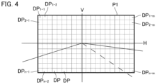
- the light distribution pattern P1 is substantially rectangular.
- the light distribution pattern P1 is formed by assembling a plurality of segmented light distribution patterns DP in the substantially positive direction.
- the light distribution pattern P1 is a set of n rows ⁇ m columns of segmented light distribution patterns DP.
- the leftmost first column in FIG. 4 is the leftmost column when the direction of travel is used as a reference, and the rightmost mth column is the rightmost column when the direction of travel is used as a reference.
- the first row is the uppermost row, and the nth row is the lowermost row.
- a portion of the segmented light distribution patterns DP is referred to as a segmented light distribution pattern DP n-m , or the like, for convenience.
- the segmented light distribution pattern DP 1-1 is the uppermost and leftmost segmented light distribution pattern
- the segmented light distribution pattern DP 2-1 is the second uppermost and leftmost segmented light distribution pattern
- the segmented light distribution pattern DP 1-2 is the uppermost and second leftmost segmented light distribution pattern
- the segmented light distribution pattern DP n-m is the lowermost, and when the direction of travel is used as a reference, rightmost segmented light distribution pattern.
- the position of each of the segmented light distribution patterns DP illustrated in FIG. 4 corresponds to the position of each of the light sources 13 illustrated in FIG. 3 . Therefore, for example, the segmented light distribution pattern DP 1-1 is a segmented light distribution pattern formed by light emitted from the light source 13 1-1 ; the segmented light distribution pattern DP 2-1 is a segmented light distribution pattern formed by light emitted from the light source 13 2-2 ; the segmented light distribution pattern DP 1-2 is a segmented light distribution pattern formed by light emitted from the light source 13 1-2 ; and the segmented light distribution pattern DP n-m is a segmented light distribution pattern formed by light emitted from the light source 13 n-m .
- the light intensity in each of the segmented light distribution patterns DP in the light distribution pattern P1 is substantially the same.
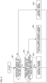
- control unit CO is connected to the power supply circuits 30, and controls the light source units 10 via the power supply circuits 30.
- the determination unit 25 is connected to the control unit CO.
- the determination unit 25 determines whether the other vehicle detected by detection device 20 satisfies a prescribed requirement based on the detection signal from the detection device 20. Examples of this prescribed requirement include that the distance between the other vehicle and the ego-vehicle 100 is less than a prescribed distance, for example.
- the prescribed distance is, for example, 100 m.
- the determination unit 25 In a case where the other vehicle is in a state of satisfying the prescribed requirement and a detection signal indicating that the other vehicle is a preceding vehicle is inputted from the detection device 20, the determination unit 25 according to the present embodiment outputs, to the control unit CO, a detection signal indicating that the other vehicle is a preceding vehicle, a signal relating to the distance from the ego-vehicle 100 to a rear windshield or a door mirror of the preceding vehicle, a signal indicating the position of the rear windshield or the door mirror of the preceding vehicle with respect to the ego-vehicle 100, and the like.
- the determination unit 25 outputs, to the control unit CO, a detection signal indicating that the other vehicle is an oncoming vehicle, a signal indicating the distance from the ego-vehicle 100 to the front windshield of the oncoming vehicle, a signal indicating the position of the front windshield of the oncoming vehicle with respect to the ego-vehicle 100, and the like.
- the determination unit 25 does not output the signal to the control unit CO.
- the determination by determination unit 25 is to change the signals to be output in different cases, according to the detection signal inputted from the detection device 20.
- a detection signal indicating that another vehicle is an oncoming vehicle may be simply described as an oncoming vehicle detection signal
- a detection signal indicating that another vehicle is a preceding vehicle may be simply described as a preceding vehicle detection signal.
- the power supply circuit 30 includes a driver, and adjusts the power supplied to each of the light sources 13 by the driver when a signal is inputted from the control unit CO. As a result, the intensity of the light emitted from each of the light sources 13 is adjusted.
- the driver of the power supply circuit 30 may adjust the power supplied to each light source 13 by using PWM (Pulse Width Modulation) control. In this case, the intensity of the light emitted from each of the light sources 13 is adjusted by adjusting the duty cycle.
- the memory ME is connected to the control unit CO, stores information, and is configured to be able to read the stored information.
- the memory ME is, for example, a non-transitory recording medium, and is preferably a semiconductor recording medium such as a RAM (Random Access Memory) or a ROM (Read Only Memory), but may include a recording medium of any format such as an optical recording medium or a magnetic recording medium. Note that the "non-transitory" recording medium includes all data-readable recording media except for a transitory, propagating signal, and does not exclude a volatile recording medium.
- the memory ME stores, for example, a table in which information on a light distribution pattern formed by light emitted from the light source unit 10 and information on other vehicles detected by the detection device 20 are associated with each other.
- Examples of the information on the light distribution pattern formed by the light emitted from the light source unit 10 may include information on the power supplied to each light source 13, or the like.
- Examples of the information on the power supplied to each light source 13 include information on the power supplied to each light source 13 in a case where another vehicle is not detected, information on the power supplied to each light source in a case where another vehicle is detected, and information on the tilt angle of the ego-vehicle 100, and so forth.
- Examples of the information on the other vehicle detected by the detection device 20 include information on whether the other vehicle is a preceding vehicle or an oncoming vehicle, information on the distance from the ego-vehicle 100 to the front windshield, the rear windshield, and the door mirror of the other vehicle, and information on the positions of the front windshield, the rear windshield, and the door mirror of the other vehicle with respect to the ego-vehicle 100. Furthermore, examples of the information on the position of another vehicle with respect to the ego-vehicle 100 include information on the position of a pair of light spots in a captured image, and so forth.
- the detection device 20 includes a millimeter wave radar 27, a camera 28, and a detection unit 29.
- the camera 28 is attached to the front portion of the ego-vehicle 100 and captures an image of the front of the ego-vehicle 100 at prescribed time intervals, for example, 1/30 second intervals.
- examples of the camera 28 include a CCD (Charged coupled device) camera.
- the captured image photographed by the camera 28 includes at least part of a region irradiated with light emitted from the light source unit 10.
- the millimeter wave radar 27 is attached to the front of the ego-vehicle 100, emits millimeter waves toward the front, and receives the millimeter waves reflected by another vehicle.
- the detection unit 29 is connected to the millimeter wave radar 27, the camera 28, and the determination unit 25.
- the detection unit 29 detects distances to the front windshield, the rear windshield, and the door mirror of another vehicle, positions of the front windshield, the rear windshield, and the door mirror of the other vehicle with respect to the ego-vehicle 100, and the like, based on data of a captured image photographed by the camera 28 and data of millimeter waves reflected by the other vehicle and received by the millimeter wave radar 27.
- the detection unit 29 identifies whether the other vehicle is a preceding vehicle or an oncoming vehicle on the basis of the data of the captured image and the millimeter wave data.
- the detection unit 29 outputs an oncoming vehicle detection signal to the determination unit 25 in a case where a captured image in which a pair of white light spots having a higher luminance than a prescribed luminance exist at a prescribed interval in the left-right direction is inputted from the camera 28.
- the detection unit 29 calculates the distance from the ego-vehicle 100 to the front windshield of the oncoming vehicle and the position of the front windshield of the oncoming vehicle on the basis of the positions of a pair of white light spots in the captured image, the distance between the pair of white light spots, and the data from the millimeter wave radar 27, and outputs a signal indicating the distance to, and the position of, the front windshield of the oncoming vehicle to the determination unit 25.
- the detection unit 29 outputs a preceding vehicle detection signal to the determination unit 25.
- the detection unit 29 calculates the distance from the ego-vehicle 100 to the rear windshield or door mirror of the preceding vehicle and the position of the rear windshield or door mirror of the preceding vehicle on the basis of the positions of a pair of red light spots in a captured image, the distance between the pair of red light spots, and the data from the millimeter wave radar 27, and outputs a signal indicating the distance and position to the rear windshield or door mirror of the preceding vehicle to the determination unit 25.
- the detection unit 29 does not output the detection signal in a case where the captured image does not include the pair of light spots located at the prescribed interval in the left-right direction and having a higher luminance than the prescribed luminance or in a case where the millimeter waves received by the millimeter wave radar have a lower intensity than the prescribed intensity.
- the configuration of the detection device 20, a method of detecting another vehicle using the detection device 20, a method of calculating a distance from the ego-vehicle 100 to another vehicle or the position of another vehicle, a method of identifying an oncoming vehicle and a preceding vehicle, and the like, are not particularly limited.
- the detection device 20 may use a LIDAR instead of the millimeter wave radar.
- the tilt calculation device 21 includes a vehicle height sensor 22 and an arithmetic unit 23.
- the vehicle height sensor 22 is connected to the arithmetic unit 23.
- the vehicle height sensor 22 is attached to a front wheel suspension of the ego-vehicle 100, and outputs a signal indicating a displacement amount of the suspension to the arithmetic unit 23.
- the arithmetic unit 23 is connected to the control unit CO.
- the arithmetic unit 23 calculates, based on a prescribed algorithm, the tilt angle of the ego-vehicle 100 in a case where the front side of the ego-vehicle 100 is tilted so as to be higher than the rear side and the tilt angle of the ego-vehicle 100 in a case where the rear side of the ego-vehicle is tilted so as to be higher than the front side, and outputs a signal indicating the tilt angle to the control unit CO.
- the former tilt angle is represented by a plus sign
- the latter tilt angle is represented by a minus sign.
- control unit CO the determination unit 25, the detection unit 29, and the arithmetic unit 23 can employ, for example, an integrated circuit such as a microcontroller, an IC (Integrated Circuit), an LSI (Large-scale Integrated Circuit), an ASIC (Application Specific Integrated Circuit), or may use an NC (Numerical Control) device. Also, in a case where an NC device is used, a machine learning device may be used, or a machine learning device may not be used.
- NC Genetic Control
- control unit CO, the determination unit 25, the detection unit 29, and the arithmetic unit 23 may be part of an electronic control unit (ECU) of the ego-vehicle 100.
- ECU electronice control unit
- the control unit CO changes the light distribution pattern by controlling the light source unit 10 as follows, for example.
- FIG. 5 is a flowchart illustrating an example of this control by the control unit CO, and illustrates an example of the control from one time point while the ego-vehicle 100 is traveling. As illustrated in FIG. 5 , the control flow includes steps SP1 to SP5.
- step SP2 In a case where both an oncoming vehicle detection signal and a preceding vehicle detection signal, which are other vehicle detection signals, are not inputted from the detection unit 29 to the control unit CO via the determination unit 25, the control unit CO advances the control flow to step SP2. On the other hand, when either of an oncoming vehicle detection signal and a preceding vehicle detection signal, which are other vehicle detection signals, is inputted from the detection unit 29 to the control unit CO via the determination unit 25, the control unit CO advances the control flow to step SP3.
- control unit CO advances the control flow to step SP5.
- the control unit CO When a preceding vehicle detection signal, a signal indicating the distance from the ego-vehicle 100 to the rear windshield and the door mirror of the preceding vehicle, a signal indicating the position of the rear windshield and the door mirror of the preceding vehicle, and a signal in which the absolute value of the tilt of the ego-vehicle 100 is equal to or less than the threshold value are inputted to the control unit CO, the control unit CO refers to the data stored in the memory ME, and outputs a second control signal corresponding to these signals to the power supply circuit 30.
- the power supply circuit 30 adjusts the power to be supplied to the plurality of light sources 13 on the basis of the second control signal.
- the power supply circuit 30 supplies fourth power greater than zero to each of the plurality of light sources 13 arranged in the row one row above the frame FR1.
- the plurality of light sources 13 to which the fourth power is supplied are light sources 13 arranged in a broken-line frame FR5, and the light sources 13 in the frame FR5 are located immediately above the first light source.
- the power supply circuit 30 supplies fifth power greater than the fourth power to each of the light sources 13 arranged in the broken-line frame FR6 located in the row one row above the frame FR5.
- the frame FR6 is located immediately above the frame FR1 and the frame FR5.
- the power supply circuit 30 supplies sixth power greater than zero to each of the plurality of light sources 13 arranged in the column one row left of the frame FR1.
- the plurality of light sources 13 to which the sixth power is supplied are light sources 13 arranged in a broken-line frame FR7, and the light sources 13 in the frame FR7 are located immediately beside the first light source.
- the power supply circuit 30 supplies seventh power greater than the sixth power to each of the light sources 13 arranged in the broken-line frame FR8 located in the column one column to the left of the frame FR7.
- the frame FR8 is located immediately beside the frame FR1 and the frame FR7.
- the power supply circuit 30 supplies eighth power greater than zero to each of the plurality of light sources 13 arranged in the column one row right of the frame FR1.
- the plurality of light sources 13 to which the eighth power is supplied are light sources 13 arranged in a broken-line frame FR9, and the light sources 13 in the frame FR9 are located immediately beside the first light source.
- the power supply circuit 30 supplies ninth power greater than the eighth power to each of the light sources 13 arranged in the broken-line frame FR10 located in the column one column to the right of the frame FR9.
- the frame FR10 is located immediately beside the frame FR1 and the frame FR9.
- the power supply circuit 30 supplies the tenth power to each of the light sources 13 excluding the light sources 13, among the second light sources, which are located in the frame FR2 to the frame FR10.
- the 10th power is greater than the first power to the 9th power and, according to the present embodiment, is equal to the power supplied to each of the light sources 13 in the case of forming the light distribution pattern P1 illustrated in FIG. 4 .
- FIG. 7 illustrates a light distribution pattern P2 formed based on the second control signal.
- each of the plurality of first light sources in the frame FR1 emits light toward a region overlapping the detected rear windshield of the preceding vehicle 200 and the pair of left and right door mirrors and a first region AR1 surrounding said region.
- the power supplied to each of the first light sources is zero. Therefore, as illustrated in FIG. 7 , in the light distribution pattern P2, in the region overlapping the rear windshield 201 of the preceding vehicle 200 and the pair of left and right door mirrors 202 and the first region AR1 surrounding the region, the light intensity is substantially zero, and the region is darker than the surrounding region.
- the light source group 130 includes a plurality of first light sources that emit light toward the first region AR1, and in this step, the control unit CO causes each of the first light sources to emit light having a lower light intensity than in a case where no detection signal is inputted.
- the position of the lower end of the first region AR1 is below the lower end of the rear windshield 201 of the preceding vehicle 200, and according to the present embodiment, is the position of the lower ends of the pair of left and right rear lamps 203 of the preceding vehicle 200.
- a second region AR2 which is a region surrounding the first region AR1, becomes brighter than the first region AR1.
- the light sources 13 arranged in the frame FR2 are located immediately below the first light source, and hence the light emitted from each of the light sources 13 in the frame FR2 irradiates the region A1 surrounded by a substantially belt-shaped broken line located immediately below the first region AR1. In this way, the region A1 becomes a brighter region than the first region AR1.
- the light source 13 disposed in the frame FR3 is located immediately below the light source 13 disposed in the frame FR2, the light emitted from each of the light sources 13 in the frame FR3 irradiates the region A2 surrounded by a substantially belt-shaped broken line located immediately below the region A1. In this way, the region A2 becomes a brighter region than the region A1.
- the light emitted from each of the light sources 13 in the frame FR4 irradiates the region A3 surrounded by a broken line immediately below the region A2, and the region A3 is a brighter region than the region A2.
- a region including these regions A1 to A3 is a lower-side region BA1 extending downward from the first region AR1 on the lower side of the other vehicle in the second region AR2, is a region where the light intensity increases toward the lower side, and is a region where the light intensity decreases toward the first region AR1.
- a region below the region A3 is brighter than the region A3.
- the light source group 130 includes a plurality of second light sources that emit light toward the lower-side region BA1 below the first region AR1. Then, in this step, among all the second light sources that emit light toward the second region AR2 in the light source group 130, the control unit CO causes each of the second light sources that emit light toward a lower-side region BA1 lower than the first region AR1 to emit light with an increasingly lower intensity toward a side closer to the first region AR1.
- the region including these regions A4 and A5 is an upper-side region BA2 extending upward from the first region AR1 on the upper side of the other vehicle in the second region AR2, is a region where the light intensity increases toward the upper side, and is a region where the light intensity decreases toward the first region AR1.
- the region above the region A5 is brighter than the region A5. Note that the up-down width of the upper-side region BA2 including the two regions A4 and A5 is smaller than the width in the up-down direction of the lower-side region BA1 including the three regions A1 to A3.
- the light sources 13 arranged in the frame FR9 are located immediately beside the right side of the first light source in a front view, the light emitted from each of the light sources 13 in the frame FR9 irradiates the region A6 surrounded by a substantially belt-shaped broken line located immediately beside the left side of the first region AR1. In this way, the region A6 becomes a brighter region than the first region AR1.
- the light sources 13 arranged in the frame FR10 are located immediately beside the right side of the light source 13 disposed in the frame FR9 in a front view, the light emitted from each of the light sources 13 in the frame FR10 irradiates the region A7 surrounded by a substantially belt-shaped broken line located immediately beside the left side of the region A6. In this way, the region A7 becomes a brighter region than the region A6.
- the region including these regions A6 and A7 is a left-side region BA3 extending to the left side from the first region AR1 on the left side of the other vehicle in the second region AR2, is a region where the light intensity increases toward the left side, and is a region where the light intensity decreases toward the first region AR1.
- the region on the left side of the region A7 is brighter than the region A7. Note that, according to the present embodiment, the width in the left-right direction of the left-side region BA3 including the two regions A6 and A7 is smaller than the width in the up-down direction of the lower-side region BA1 including the three regions A1 to A3.
- the light source group 130 includes the plurality of second light sources that emit light toward the left-side region BA3 on the left side of the first region AR1. Then, in this step, among all the second light sources that emit light toward the second region AR2 in the light source group 130, the control unit CO causes each of the second light sources that emit light toward a left-side region BA3 to the left of the first region AR1 to emit light with an increasingly lower intensity toward a side closer to the first region AR1.
- the light sources 13 arranged in the frame FR8 are located immediately beside the left side of the light source 13 disposed in the frame FR7 in a front view, the light emitted from each of the light sources 13 in the frame FR8 irradiates the region A9 surrounded by a substantially belt-shaped broken line located immediately beside the right side of the region A8. In this way, the region A9 becomes a brighter region than the region A8.
- the region including these regions A8 and A9 is a right-side region BA4 extending rightward from the first region AR1 on the right side of the other vehicle in the second region AR2, and is a region where the light intensity increases toward the right side.
- the region on the right side of the region A9 is brighter than the region A9.
- the width in the left-right direction of the right-side region BA4 including the two regions A8 and A9 is smaller than the width in the up-down direction of the lower-side region BA1 including the three regions A1 to A3.
- control unit CO After this step, the control unit CO returns the control flow to step SP1.
- control unit CO controls the light source unit 10 as follows.
- step SP4 a case where a preceding vehicle detection signal is inputted to the control unit CO and an oncoming vehicle detection signal is not inputted to the control unit CO will be described.
- the power supply circuit 30 supplies the eleventh power, which is greater than the third power and less than the tenth power, to each of the light sources 13 located in the frame FR11 located immediately below the frame FR4.
- the frame FR11 is indicated by an alternate long-and-short dash line. Note that this step is similar to step SP4 except that the eleventh power is supplied to the light sources 13 located in the frame FR11.
- the light source 13 disposed in the frame FR11 is located immediately below the light source 13 disposed in the frame FR4. For this reason, as illustrated in FIG. 7 , the light emitted from each of the light sources 13 in the frame FR11 irradiates the region A10 surrounded by a substantially belt-shaped alternate long-and-short dash line located immediately below the region A3. In this way, the region A10 becomes a brighter region than the region A3. Note that the region below the region A10 is brighter than the region A10.
- a region including the regions A1 to A3 and A10 is a lower-side region BA1 extending downward from the first region AR1 on the lower side of the other vehicle in the second region AR2, is a region where the light intensity increases toward the lower side, and is a region where the light intensity decreases toward the first region AR1.
- the lower-side region BA1 in this step includes four regions A1 to A3, and A10. Therefore, the width in the up-down direction of the lower-side region BA1 in this step is greater than the width in the up-down direction of the lower-side region BA1 in step SP4.
- the power supply circuit 30 Based on the third control signal, the power supply circuit 30 adjusts the power supplied to the light source group 130 such that the power applied to the lower row increases as the signal indicating the tilt of the ego-vehicle 100 indicates a greater tilt. In this way, in a case where the ego-vehicle 100 is tilted such that the front side of the ego-vehicle 100 is higher than the rear side, the control unit CO increases the width of the lower-side region BA1 in the up-down direction as the tilt of the ego-vehicle 100 increases.
- the control unit CO refers to the data stored in the memory ME and outputs a fourth control signal corresponding to these signals to the power supply circuit 30.
- the light sources 13 arranged in the frame FR12 are located immediately above the light sources 13 arranged in the frame FR6. For this reason, as illustrated in FIG. 7 , the light emitted from each of the light sources 13 in the frame FR12 irradiates the region A11 located immediately above the region A5 and surrounded by a substantially belt-shaped alternate long-and-short dash line. In this way, region A11 becomes a brighter region than region A5. Note that the region above region A11 is brighter than region A11.
- the region including the regions A4, A5, and A11 is an upper-side region BA2 extending upward from the first region AR1 on the upper side of the other vehicle in the second region AR2, is a region where the light intensity increases toward the upper side, and is a region where the light intensity decreases toward the first region AR1.
- the upper-side region BA2 in this step includes three regions A4, A5, and A11. Therefore, the width in the up-down direction of the upper-side region BA2 in this step is greater than the width in the up-down direction of the upper-side region BA2 in step SP4.
- the power supply circuit 30 Based on the fourth control signal, the power supply circuit 30 adjusts the power supplied to the light source group 130 such that the power applied to the upper row increases as the signal indicating the tilt of the ego-vehicle 100 indicates a greater tilt. In this way, in a case where the ego-vehicle 100 is tilted such that the rear side of the ego-vehicle 100 is higher than the front side, the control unit CO increases the width of the upper-side region BA2 in the up-down direction as the tilt of the ego-vehicle 100 increases.
- control unit CO After this step, the control unit CO returns the control flow to step SP1.
- the control unit CO similarly performs the control in a case where the detection signal of the oncoming vehicle is inputted.
- a light distribution pattern P3 illustrated in FIG. 8 is formed in step SP4.
- the light distribution pattern P3 includes a first region AR1 including a region overlapping a front windshield 301 of the oncoming vehicle 300 and a second region AR2 surrounding the first region AR1.
- the first region AR1 is darker than the second region AR2.
- the front windshield 301 is a visual recognition part of the oncoming vehicle 300 for the driver of the oncoming vehicle 300 to visually recognize the outside of the vehicle.
- the position of the lower end of the first region AR1 is below the lower end of the front windshield 301 of the oncoming vehicle 300, and according to the present embodiment, is the position of the lower ends of a pair of left and right headlamps 303 of the oncoming vehicle 300.
- the second region AR2 includes a lower-side region BA1 including the regions A1 to A3, an upper-side region BA2 including the regions A4 and A5, a left-side region BA3 including the regions A6 and A7, and a right-side region BA4 including the regions A8 and A9.
- the control unit CO performs step SP5 to form a lower-side region BA1 which includes the regions A1 to A3 and A10 or an upper-side region BA2 which includes the regions A4, A5 and A11.
- a lower-side region BA1 including the regions A1 to A3, and A10 or an upper-side region BA2 including the regions A4, A5, and A11 is formed in each of the preceding vehicle 200 and the oncoming vehicle 300.
- the vehicle headlight 1 is equipped with the light source unit 10 for forming a light distribution pattern which can be changed by light beams emitted from the light source group 130; and the control unit CO.
- the control unit CO causes each of the first light sources, which emit light toward the first region AR1 including the region overlapping the visual recognition part of the other vehicle in the light source group 130, to emit light having a lower intensity than in a case where no detection signal is inputted, and causes, among second light sources that emit light toward a second region AR2 surrounding a first region AR1 in the light source group 130, the second light source which emits light toward a lower-side region BA1 below the first region, to emit light with an increasingly lower intensity toward the side closer to the first region AR1.
- the first region AR1 including the region overlapping the visual recognition part of the other vehicle becomes darker than in the case where no detection signal is inputted. Therefore, dazzling of other vehicles when performing ADB control can be suppressed.
- the first region AR1 acts as a dazzling suppression region that suppresses dazzling of another vehicle.
- control unit CO causes second light sources, which emit light toward a lower-side region BA1 of the second region AR2 located below the first region AR1 to emit light with an increasingly lower intensity toward a side closer to the first region AR1. Therefore, in this vehicle headlight 1, gradation in which the light intensity decreases toward the first region AR1 is formed in the lower-side region BA1 located below the first region AR1. In this way, the lower-side region in the second region AR2 becomes darker toward the first region AR1.
- the control unit CO causes the second light source that emits light toward the upper-side region BA2 above the first region AR1 in the second region AR2 to emit light with an increasingly lower intensity toward a side closer to the first region AR1.
- gradation in which the light intensity decreases toward the first region AR1 is formed in the second region AR2 located above the first region AR1. In this way, the upper-side region in the second region AR2 becomes darker toward the first region AR1.
- the control unit CO increases the width of the upper-side region BA2 in the up-down direction as the tilt of the ego-vehicle 100 increases.
- the upper-side region BA2 where the gradation is formed is more likely to overlap the visual recognition part of another vehicle. For this reason, it is possible to suppress dazzling of another vehicle more effectively when performing ADB control.
- the control unit CO causes at least one second light source of: a second light source that emits light toward the left-side region BA3 on the left side of the first region AR1 among the second light sources, and a second light source that emits light toward the right-side region BA4 on the right side of the first region AR1 among the second light sources, to emit light with an increasingly lower intensity toward the side closer to the first region AR1.
- gradation in which the light intensity decreases toward the first region AR1 is formed in the second region AR2 located on the left side of the first region AR1.
- the left-side region BA3 becomes darker toward the first region AR1.
- gradation in which the light intensity decreases toward the first region AR1 is formed in the second region AR2 located on the right side of the first region AR1.
- the right-side region BA4 becomes darker toward the first region AR1. Therefore, even in a case where at least one of the left-side region and the right-side region of the second region AR2 overlaps the visual recognition part of the other vehicle due to a change in the relative position between the ego-vehicle and the other vehicle in the left-right direction, this gradation is interposed, and therefore the visual recognition part of another vehicle is prevented from being suddenly brightly irradiated. Thus, it is possible to suppress dazzling of another vehicle more effectively when performing ADB control. Note that it is not essential to form the left-side region BA3 and the right-side region BA4 having such gradation.
- the width in the left-right direction of the left-side region BA3 and the right-side region BA4, respectively, is smaller than the width in the up-down direction of the lower-side region BA1.
- the region where the gradation is not formed in the second region AR2 can be expanded in comparison with the case where the width in the left-right direction of the left-side region BA3 and the right-side region BA4, respectively, is equal to or greater than the width in the up-down direction of the lower-side region BA1.
- the region where the gradation is not formed is located on the side opposite to the first region AR1 side of a left-side region BA3 and a right-side region BA4, respectively, this region is substantially brighter than the left-side region BA3 and the right-side region BA4. Therefore, because the region in which the gradation is not formed in the second region AR2 is widened, the front of the ego-vehicle 100 can be brightened, and the visibility when performing ADB control can be improved.
- the width in the left-right direction of the left-side region BA3 and the right-side region BA4, respectively, is smaller than the width in the up-down direction of the lower-side region BA1.
- only one of the width of the left-side region BA3 in the left-right direction and the width of the right-side region BA4 in the left-right direction may be made smaller than the width of the lower-side region BA1 in the up-down direction.
- the width in the up-down direction of the upper-side region BA2 is smaller than the width in the up-down direction of the lower-side region BA1. In this way, the visibility of the upper side can be enhanced.
- a changeable light distribution pattern formed by each light emitted from the light source unit 10 is not limited to the light distribution pattern disclosed in the above embodiment.
- control unit CO may make the ratio of the width WF3 in the left-right direction of the left-side region BA3 to the width WF1 in the left-right direction of the first region AR1, in a case where the other vehicle is the oncoming vehicle 300, greater than the ratio of the width WL3 in the left-right direction of the left-side region BA3 to the width WL1 in the left-right direction of the first region AR1 in a case where the other vehicle is the preceding vehicle 200.
- the number of first light sources that emit light toward the first region AR1 and are aligned in the left-right direction is represented by a number A1
- the number of second light sources that increase in the power supplied with increasing distance from the first region AR1 in the left-right direction in the left-side region BA3 is represented by a number B1.
- the number of first light sources that emit light toward the first region AR1 and are aligned in the left-right direction is represented by a number C1
- the number of second light sources that increase in the power supplied with increasing distance from the first region AR1 in the left-right direction in the left-side region BA3 is represented by a number D1.
- the power supply circuit 30 may adjust the power supplied to the light source group 130 such that the ratio of the number B1 to the number A1 becomes greater than the ratio of the number D1 to the number C1.
- the number of first light sources that emit light toward the first region AR1 and are aligned in the left-right direction is represented by a number A2
- the number of second light sources that increase in the power supplied with increasing distance from the first region AR1 in the left-right direction in the right-side region BA4 is represented by a number B2.
- the number of first light sources that emit light toward the first region AR1 and are aligned in the left-right direction is represented by a number C2
- the number of second light sources that increase in the power supplied with increasing distance from the first region AR1 in the left-right direction in the right-side region BA4 is represented by a number D2.
- the power supply circuit 30 may adjust the power supplied to the light source group 130 such that the ratio of the number B2 to the number A2 becomes greater than the ratio of the number D2 to the number C2.
- the oncoming vehicle approaches more rapidly than the preceding vehicle. For this reason, the relative position in the left-right direction between the ego-vehicle and the oncoming vehicle is easily shifted to the left side and the right side in comparison with the relative position in the left-right direction between the ego-vehicle and the preceding vehicle.
- the visual recognition part of the approaching oncoming vehicle 300 can be prevented from being suddenly brightly irradiated by interposing the left-side region BA3 or the right-side region BA4 where gradation is formed.
- a width in the left-right direction in a third region which is the region farther from the ego-vehicle 100 out of the left-side region BA3 and the right-side region BA4 in a case where the other vehicle is an oncoming vehicle 300, may be greater than a width in the left-right direction in a fourth region, which is the region closer to the ego-vehicle 100 out of the left-side region BA3 and the right-side region BA4 in a case where the other vehicle is the oncoming vehicle 300.
- the power supply circuit 30 may adjust the power supplied to the light source group 130 such that the width in the left-right direction in the third region is greater than the width in the left-right direction in the fourth region.
- the right-side region BA4 is the third region AR3, and the left-side region BA3 is the fourth region AR4.
- the width WF4 in the left-right direction of the right-side region BA4 may be greater than the width WF3 in the left-right direction of the left-side region BA3.
- the width WF4 in the left-right direction of the right-side region BA4 is made greater than the width WF3 in the left-right direction of the left-side region BA3.
- the visual recognition part of the oncoming vehicle 300 can be prevented from being suddenly brightly irradiated by interposing the right-side region BA4 where gradation is formed.
- a vehicle headlight capable of suppressing dazzling of other vehicles when performing ADB control is provided, and can be used in the field of automobiles and the like.
Landscapes
- Engineering & Computer Science (AREA)
- General Engineering & Computer Science (AREA)
- Physics & Mathematics (AREA)
- Mechanical Engineering (AREA)
- Microelectronics & Electronic Packaging (AREA)
- Optics & Photonics (AREA)
- Spectroscopy & Molecular Physics (AREA)
- Mathematical Physics (AREA)
- Lighting Device Outwards From Vehicle And Optical Signal (AREA)
Claims (6)
- Scheinwerfer für Fahrzeuge (1), umfassend:eine Lichtquelleneinheit (10) zur Bildung eines Lichtverteilungsmusters, das durch von einer Lichtquellengruppe (130) der Lichtquelleneinheit (10) emittierte Lichtstrahlen verändert werden kann; undeine Steuereinheit (CO),wobei in einem Fall, in dem ein Detektionssignal eines anderen Fahrzeugs (200, 300), das sich vor einem Ego-Fahrzeug (100) befindet, von einer Detektionseinheit (29) zum Detektieren des anderen Fahrzeugs eingegeben wird, die Steuereinheit veranlasst, dass erste Lichtquellen der Lichtquellengruppe (130), die Licht in Richtung eines ersten Bereichs (AR1) emittieren, der einen Bereich einschließt, der einen visuellen Erkennungsteil (201, 202, 301) des anderen Fahrzeugs überlappt, der von einem Fahrer desselben verwendet wird, um die Außenseite des anderen Fahrzeugs (200, 300) visuell zu erkennen, um Licht mit einer geringeren Intensität zu emittieren als in einem Fall, in dem kein Detektionssignal eingegeben wird, und veranlasst, dass unter zweiten Lichtquellen der Lichtquellengruppe (130), die Licht in Richtung eines zweiten Bereichs (AR2), der den ersten Bereich (AR1) umgibt, emittieren, die zweiten Lichtquellen, die Licht in Richtung eines Unterseitenbereichs (BA1), der niedriger als der erste Bereich ist, emittieren, Licht mit einer zunehmend geringeren Intensität in Richtung der Seite, die näher an dem ersten Bereich (AR1) liegt, emittieren; und dadurch gekennzeichnet, dassin einem Fall, in dem das Ego-Fahrzeug (100) so geneigt ist, dass die Vorderseite des Ego-Fahrzeugs höher ist als die Rückseite, die Steuereinheit (CO) eine Breite in einer Auf-Ab-Richtung des unteren Bereichs (BA1) vergrößert, wenn die Neigung des Ego-Fahrzeugs zunimmt.
- Scheinwerfer für Fahrzeuge nach Anspruch 1,
wobei in einem Fall, in dem das Detektionssignal von der Detektionseinheit (29) eingegeben wird, die Steuereinheit (CO) veranlasst, dass unter den zweiten Lichtquellen die zweite Lichtquelle, die Licht in Richtung eines Oberseitenbereichs (BA2) oberhalb des ersten Bereichs (AR1) emittiert, Licht mit einer zunehmend geringeren Intensität in Richtung der Seite emittiert, die näher an dem ersten Bereich (AR1) liegt. - Scheinwerfer für Fahrzeuge nach Anspruch 2,
wobei in einem Fall, in dem das Ego-Fahrzeug (100) so geneigt ist, dass die Rückseite des Ego-Fahrzeugs höher ist als die Vorderseite, die Steuereinheit (CO) die Breite in der Auf-Ab-Richtung des Oberseitenbereichs (BA2) vergrößert, wenn die Neigung des Ego-Fahrzeugs (100) zunimmt. - Scheinwerfer für Fahrzeuge nach einem der Ansprüche 1 bis 3,
wobei in einem Fall, in dem das Detektionssignal von der Detektionseinheit (29) eingegeben wird, die Steuereinheit (CO) veranlasst, dass mindestens eine zweite Lichtquelle von: einer zweiten Lichtquelle, die Licht in Richtung eines Linksseitenbereichs (BA3) auf einer linken Seite des ersten Bereichs emittiert, unter den zweiten Lichtquellen, und einer zweiten Lichtquelle, die Licht in Richtung eines Rechtsseitenbereichs (BA4) auf einer rechten Seite des ersten Bereichs (AR1) emittiert, unter den zweiten Lichtquellen, Licht mit einer zunehmend geringeren Intensität in Richtung der Seite, die näher an dem ersten Bereich (AR1) liegt, emittiert. - Scheinwerfer für Fahrzeuge nach Anspruch 4,
wobei mindestens eine von einer Breite in einer Links-Rechts-Richtung des Linksseitenbereichs (BA3) und einer Breite in der Links-Rechts-Richtung des Rechtsseitenbereichs (BA4) kleiner ist als eine Breite in der Auf-Ab-Richtung des Unterseitenbereichs (BA1). - Scheinwerfer für Fahrzeuge nach Anspruch 4 oder 5,
wobei eine Breite (WF4, WF3) in der Links-Rechts-Richtung in einem dritten Bereich (AR3), der in einem Fall, in dem das andere Fahrzeug ein entgegenkommendes Fahrzeug (300) ist, der von dem Ego-Fahrzeug (100) weiter entfernte Bereich aus dem Linksseitenbereich (BA3) und dem Rechtsseitenbereich (BA4) ist, größer ist als eine Breite (WF3, WF4) in der Links-Rechts-Richtung in einem vierten Bereich (AR4), der der Bereich aus dem Linksseitenbereich (BA3) und dem Rechtsseitenbereich (BA4) ist, der näher an dem Ego-Fahrzeug (100) liegt, in einem Fall, in dem das andere Fahrzeug ein entgegenkommendes Fahrzeug (300) ist.
Applications Claiming Priority (2)
| Application Number | Priority Date | Filing Date | Title |
|---|---|---|---|
| JP2021021926 | 2021-02-15 | ||
| PCT/JP2022/004320 WO2022172860A1 (ja) | 2021-02-15 | 2022-02-03 | 車両用前照灯 |
Publications (3)
| Publication Number | Publication Date |
|---|---|
| EP4292883A1 EP4292883A1 (de) | 2023-12-20 |
| EP4292883A4 EP4292883A4 (de) | 2024-01-10 |
| EP4292883B1 true EP4292883B1 (de) | 2024-11-20 |
Family
ID=82837877
Family Applications (1)
| Application Number | Title | Priority Date | Filing Date |
|---|---|---|---|
| EP22752687.8A Active EP4292883B1 (de) | 2021-02-15 | 2022-02-03 | Scheinwerfer für fahrzeuge |
Country Status (5)
| Country | Link |
|---|---|
| US (1) | US20240116428A1 (de) |
| EP (1) | EP4292883B1 (de) |
| JP (1) | JP7746312B2 (de) |
| CN (1) | CN116867677A (de) |
| WO (1) | WO2022172860A1 (de) |
Families Citing this family (3)
| Publication number | Priority date | Publication date | Assignee | Title |
|---|---|---|---|---|
| EP4588720A4 (de) * | 2022-09-14 | 2025-08-20 | Koito Mfg Co Ltd | Scheinwerfer für fahrzeuge |
| JP2024049632A (ja) | 2022-09-29 | 2024-04-10 | トヨタ自動車株式会社 | 車両用前照灯の制御装置、制御方法及び、プログラム |
| WO2025018158A1 (ja) * | 2023-07-20 | 2025-01-23 | 株式会社小糸製作所 | 灯具ユニットの制御装置、プログラム、及び車両用前照灯 |
Family Cites Families (15)
| Publication number | Priority date | Publication date | Assignee | Title |
|---|---|---|---|---|
| US8017898B2 (en) * | 2007-08-17 | 2011-09-13 | Magna Electronics Inc. | Vehicular imaging system in an automatic headlamp control system |
| JP5808620B2 (ja) * | 2011-09-06 | 2015-11-10 | 株式会社小糸製作所 | 車両用前照灯装置および車両用前照灯制御システム |
| WO2015046346A1 (ja) * | 2013-09-26 | 2015-04-02 | 株式会社小糸製作所 | 車両用灯具制御システム |
| JP5955356B2 (ja) * | 2014-08-01 | 2016-07-20 | 株式会社豊田中央研究所 | 照明装置 |
| JP6453669B2 (ja) * | 2015-02-27 | 2019-01-16 | トヨタ自動車株式会社 | 車両用前照灯制御装置 |
| US9855887B1 (en) * | 2015-07-28 | 2018-01-02 | Apple Inc. | Dynamic control of projected light relative to a scene |
| JP6751307B2 (ja) * | 2016-05-17 | 2020-09-02 | スタンレー電気株式会社 | 車両用灯具 |
| KR101938669B1 (ko) * | 2017-06-22 | 2019-01-15 | 엘지전자 주식회사 | 차량용 램프 및 그것의 제어방법 |
| JP7081934B2 (ja) * | 2018-02-14 | 2022-06-07 | スタンレー電気株式会社 | 車両用灯具の点灯制御装置、車両用灯具の点灯制御方法、車両用灯具システム |
| JP7265306B2 (ja) * | 2018-09-28 | 2023-04-26 | 株式会社小糸製作所 | 車両用前照灯 |
| KR102127614B1 (ko) * | 2018-11-05 | 2020-06-29 | 현대모비스 주식회사 | 헤드램프 제어 장치 및 방법 |
| EP3671015B1 (de) * | 2018-12-19 | 2023-01-11 | Valeo Vision | Verfahren zur korrektur eines lichtmusters und fahrzeugbeleuchtungsvorrichtung |
| JP7201425B2 (ja) * | 2018-12-26 | 2023-01-10 | 株式会社小糸製作所 | 車両用灯具システム、車両用灯具の制御装置および車両用灯具の制御方法 |
| JP2020131922A (ja) | 2019-02-20 | 2020-08-31 | 株式会社小糸製作所 | 車両用灯具 |
| FR3099541B1 (fr) * | 2019-07-31 | 2024-09-20 | Valeo Vision | Procede de contrôle d’un dispositif lumineux apte a emettre deux faisceaux lumineux pixelises de resolutions differentes |
-
2022
- 2022-02-03 WO PCT/JP2022/004320 patent/WO2022172860A1/ja not_active Ceased
- 2022-02-03 JP JP2022580600A patent/JP7746312B2/ja active Active
- 2022-02-03 EP EP22752687.8A patent/EP4292883B1/de active Active
- 2022-02-03 CN CN202280014708.5A patent/CN116867677A/zh active Pending
- 2022-02-03 US US18/276,913 patent/US20240116428A1/en active Pending
Also Published As
| Publication number | Publication date |
|---|---|
| JP7746312B2 (ja) | 2025-09-30 |
| US20240116428A1 (en) | 2024-04-11 |
| EP4292883A1 (de) | 2023-12-20 |
| WO2022172860A1 (ja) | 2022-08-18 |
| EP4292883A4 (de) | 2024-01-10 |
| JPWO2022172860A1 (de) | 2022-08-18 |
| CN116867677A (zh) | 2023-10-10 |
Similar Documents
| Publication | Publication Date | Title |
|---|---|---|
| EP4292883B1 (de) | Scheinwerfer für fahrzeuge | |
| US12059996B2 (en) | Vehicle headlight | |
| US9494288B2 (en) | Automotive headlamp apparatus | |
| US11648870B2 (en) | Vehicle headlamp | |
| CN117759887A (zh) | 具有混合矩阵低光束的车辆前灯组件和系统 | |
| US20250222856A1 (en) | Vehicle headlamp | |
| US12409775B2 (en) | Vehicle headlamp having a lamp unit with a matrix of light emitting units emitting a plurality of irradiation spots and a boundary determination unit and control unit controlling the boundary illuminance | |
| US12214716B2 (en) | Vehicle headlight and vehicle headlight system | |
| JP7561183B2 (ja) | 車両用前照灯及び車両用前照灯システム | |
| US11970108B2 (en) | Headlight device | |
| US12066161B2 (en) | Vehicle headlamps | |
| KR20220153803A (ko) | 차량용 헤드램프 모듈 및 이를 이용한 지능형 헤드램프 | |
| JP7559661B2 (ja) | 車両用灯具の制御装置、及び車両用灯具 | |
| EP4588720A1 (de) | Scheinwerfer für fahrzeuge | |
| WO2021153775A1 (ja) | 車両用前照灯 |
Legal Events
| Date | Code | Title | Description |
|---|---|---|---|
| STAA | Information on the status of an ep patent application or granted ep patent |
Free format text: STATUS: THE INTERNATIONAL PUBLICATION HAS BEEN MADE |
|
| PUAI | Public reference made under article 153(3) epc to a published international application that has entered the european phase |
Free format text: ORIGINAL CODE: 0009012 |
|
| STAA | Information on the status of an ep patent application or granted ep patent |
Free format text: STATUS: REQUEST FOR EXAMINATION WAS MADE |
|
| 17P | Request for examination filed |
Effective date: 20230913 |
|
| AK | Designated contracting states |
Kind code of ref document: A1 Designated state(s): AL AT BE BG CH CY CZ DE DK EE ES FI FR GB GR HR HU IE IS IT LI LT LU LV MC MK MT NL NO PL PT RO RS SE SI SK SM TR |
|
| A4 | Supplementary search report drawn up and despatched |
Effective date: 20231212 |
|
| RIC1 | Information provided on ipc code assigned before grant |
Ipc: F21W 102/20 20180101ALI20231206BHEP Ipc: F21W 102/14 20180101ALI20231206BHEP Ipc: F21S 41/153 20180101ALI20231206BHEP Ipc: F21S 41/148 20180101ALI20231206BHEP Ipc: F21V 14/04 20060101ALI20231206BHEP Ipc: F21V 9/40 20180101ALI20231206BHEP Ipc: F21V 7/00 20060101ALI20231206BHEP Ipc: F21Y 115/10 20160101ALI20231206BHEP Ipc: B60Q 1/14 20060101AFI20231206BHEP |
|
| DAV | Request for validation of the european patent (deleted) | ||
| DAX | Request for extension of the european patent (deleted) | ||
| GRAP | Despatch of communication of intention to grant a patent |
Free format text: ORIGINAL CODE: EPIDOSNIGR1 |
|
| STAA | Information on the status of an ep patent application or granted ep patent |
Free format text: STATUS: GRANT OF PATENT IS INTENDED |
|
| RIC1 | Information provided on ipc code assigned before grant |
Ipc: F21W 102/19 20180101ALN20240507BHEP Ipc: F21W 102/145 20180101ALN20240507BHEP Ipc: F21W 102/13 20180101ALN20240507BHEP Ipc: F21S 41/663 20180101ALN20240507BHEP Ipc: F21S 41/151 20180101ALN20240507BHEP Ipc: F21S 41/143 20180101ALN20240507BHEP Ipc: F21S 41/153 20180101ALI20240507BHEP Ipc: B60Q 1/14 20060101AFI20240507BHEP |
|
| INTG | Intention to grant announced |
Effective date: 20240605 |
|
| GRAJ | Information related to disapproval of communication of intention to grant by the applicant or resumption of examination proceedings by the epo deleted |
Free format text: ORIGINAL CODE: EPIDOSDIGR1 |
|
| STAA | Information on the status of an ep patent application or granted ep patent |
Free format text: STATUS: REQUEST FOR EXAMINATION WAS MADE |
|
| GRAP | Despatch of communication of intention to grant a patent |
Free format text: ORIGINAL CODE: EPIDOSNIGR1 |
|
| STAA | Information on the status of an ep patent application or granted ep patent |
Free format text: STATUS: GRANT OF PATENT IS INTENDED |
|
| INTC | Intention to grant announced (deleted) | ||
| RIC1 | Information provided on ipc code assigned before grant |
Ipc: F21W 102/19 20180101ALN20240717BHEP Ipc: F21W 102/145 20180101ALN20240717BHEP Ipc: F21W 102/13 20180101ALN20240717BHEP Ipc: F21S 41/663 20180101ALN20240717BHEP Ipc: F21S 41/151 20180101ALN20240717BHEP Ipc: F21S 41/143 20180101ALN20240717BHEP Ipc: F21S 41/153 20180101ALI20240717BHEP Ipc: B60Q 1/14 20060101AFI20240717BHEP |
|
| INTG | Intention to grant announced |
Effective date: 20240805 |
|
| GRAS | Grant fee paid |
Free format text: ORIGINAL CODE: EPIDOSNIGR3 |
|
| GRAA | (expected) grant |
Free format text: ORIGINAL CODE: 0009210 |
|
| STAA | Information on the status of an ep patent application or granted ep patent |
Free format text: STATUS: THE PATENT HAS BEEN GRANTED |
|
| AK | Designated contracting states |
Kind code of ref document: B1 Designated state(s): AL AT BE BG CH CY CZ DE DK EE ES FI FR GB GR HR HU IE IS IT LI LT LU LV MC MK MT NL NO PL PT RO RS SE SI SK SM TR |
|
| REG | Reference to a national code |
Ref country code: GB Ref legal event code: FG4D |
|
| REG | Reference to a national code |
Ref country code: CH Ref legal event code: EP |
|
| REG | Reference to a national code |
Ref country code: DE Ref legal event code: R096 Ref document number: 602022007993 Country of ref document: DE |
|
| REG | Reference to a national code |
Ref country code: IE Ref legal event code: FG4D |
|
| P01 | Opt-out of the competence of the unified patent court (upc) registered |
Free format text: CASE NUMBER: APP_62716/2024 Effective date: 20241125 |
|
| REG | Reference to a national code |
Ref country code: LT Ref legal event code: MG9D |
|
| REG | Reference to a national code |
Ref country code: NL Ref legal event code: MP Effective date: 20241120 |
|
| PG25 | Lapsed in a contracting state [announced via postgrant information from national office to epo] |
Ref country code: IS Free format text: LAPSE BECAUSE OF FAILURE TO SUBMIT A TRANSLATION OF THE DESCRIPTION OR TO PAY THE FEE WITHIN THE PRESCRIBED TIME-LIMIT Effective date: 20250320 Ref country code: HR Free format text: LAPSE BECAUSE OF FAILURE TO SUBMIT A TRANSLATION OF THE DESCRIPTION OR TO PAY THE FEE WITHIN THE PRESCRIBED TIME-LIMIT Effective date: 20241120 Ref country code: PT Free format text: LAPSE BECAUSE OF FAILURE TO SUBMIT A TRANSLATION OF THE DESCRIPTION OR TO PAY THE FEE WITHIN THE PRESCRIBED TIME-LIMIT Effective date: 20250320 |
|
| PGFP | Annual fee paid to national office [announced via postgrant information from national office to epo] |
Ref country code: DE Payment date: 20250114 Year of fee payment: 4 |
|
| PG25 | Lapsed in a contracting state [announced via postgrant information from national office to epo] |
Ref country code: FI Free format text: LAPSE BECAUSE OF FAILURE TO SUBMIT A TRANSLATION OF THE DESCRIPTION OR TO PAY THE FEE WITHIN THE PRESCRIBED TIME-LIMIT Effective date: 20241120 Ref country code: NL Free format text: LAPSE BECAUSE OF FAILURE TO SUBMIT A TRANSLATION OF THE DESCRIPTION OR TO PAY THE FEE WITHIN THE PRESCRIBED TIME-LIMIT Effective date: 20241120 |
|
| REG | Reference to a national code |
Ref country code: AT Ref legal event code: MK05 Ref document number: 1743301 Country of ref document: AT Kind code of ref document: T Effective date: 20241120 |
|
| PG25 | Lapsed in a contracting state [announced via postgrant information from national office to epo] |
Ref country code: BG Free format text: LAPSE BECAUSE OF FAILURE TO SUBMIT A TRANSLATION OF THE DESCRIPTION OR TO PAY THE FEE WITHIN THE PRESCRIBED TIME-LIMIT Effective date: 20241120 |
|
| PG25 | Lapsed in a contracting state [announced via postgrant information from national office to epo] |
Ref country code: ES Free format text: LAPSE BECAUSE OF FAILURE TO SUBMIT A TRANSLATION OF THE DESCRIPTION OR TO PAY THE FEE WITHIN THE PRESCRIBED TIME-LIMIT Effective date: 20241120 |
|
| PG25 | Lapsed in a contracting state [announced via postgrant information from national office to epo] |
Ref country code: NO Free format text: LAPSE BECAUSE OF FAILURE TO SUBMIT A TRANSLATION OF THE DESCRIPTION OR TO PAY THE FEE WITHIN THE PRESCRIBED TIME-LIMIT Effective date: 20250220 |
|
| PG25 | Lapsed in a contracting state [announced via postgrant information from national office to epo] |
Ref country code: GR Free format text: LAPSE BECAUSE OF FAILURE TO SUBMIT A TRANSLATION OF THE DESCRIPTION OR TO PAY THE FEE WITHIN THE PRESCRIBED TIME-LIMIT Effective date: 20250221 Ref country code: AT Free format text: LAPSE BECAUSE OF FAILURE TO SUBMIT A TRANSLATION OF THE DESCRIPTION OR TO PAY THE FEE WITHIN THE PRESCRIBED TIME-LIMIT Effective date: 20241120 Ref country code: LV Free format text: LAPSE BECAUSE OF FAILURE TO SUBMIT A TRANSLATION OF THE DESCRIPTION OR TO PAY THE FEE WITHIN THE PRESCRIBED TIME-LIMIT Effective date: 20241120 |
|
| PG25 | Lapsed in a contracting state [announced via postgrant information from national office to epo] |
Ref country code: PL Free format text: LAPSE BECAUSE OF FAILURE TO SUBMIT A TRANSLATION OF THE DESCRIPTION OR TO PAY THE FEE WITHIN THE PRESCRIBED TIME-LIMIT Effective date: 20241120 |
|
| PG25 | Lapsed in a contracting state [announced via postgrant information from national office to epo] |
Ref country code: RS Free format text: LAPSE BECAUSE OF FAILURE TO SUBMIT A TRANSLATION OF THE DESCRIPTION OR TO PAY THE FEE WITHIN THE PRESCRIBED TIME-LIMIT Effective date: 20250220 |
|
| PG25 | Lapsed in a contracting state [announced via postgrant information from national office to epo] |
Ref country code: SM Free format text: LAPSE BECAUSE OF FAILURE TO SUBMIT A TRANSLATION OF THE DESCRIPTION OR TO PAY THE FEE WITHIN THE PRESCRIBED TIME-LIMIT Effective date: 20241120 |
|
| PG25 | Lapsed in a contracting state [announced via postgrant information from national office to epo] |
Ref country code: DK Free format text: LAPSE BECAUSE OF FAILURE TO SUBMIT A TRANSLATION OF THE DESCRIPTION OR TO PAY THE FEE WITHIN THE PRESCRIBED TIME-LIMIT Effective date: 20241120 |
|
| PG25 | Lapsed in a contracting state [announced via postgrant information from national office to epo] |
Ref country code: EE Free format text: LAPSE BECAUSE OF FAILURE TO SUBMIT A TRANSLATION OF THE DESCRIPTION OR TO PAY THE FEE WITHIN THE PRESCRIBED TIME-LIMIT Effective date: 20241120 |
|
| PG25 | Lapsed in a contracting state [announced via postgrant information from national office to epo] |
Ref country code: RO Free format text: LAPSE BECAUSE OF FAILURE TO SUBMIT A TRANSLATION OF THE DESCRIPTION OR TO PAY THE FEE WITHIN THE PRESCRIBED TIME-LIMIT Effective date: 20241120 |
|
| PG25 | Lapsed in a contracting state [announced via postgrant information from national office to epo] |
Ref country code: SK Free format text: LAPSE BECAUSE OF FAILURE TO SUBMIT A TRANSLATION OF THE DESCRIPTION OR TO PAY THE FEE WITHIN THE PRESCRIBED TIME-LIMIT Effective date: 20241120 |
|
| PG25 | Lapsed in a contracting state [announced via postgrant information from national office to epo] |
Ref country code: CZ Free format text: LAPSE BECAUSE OF FAILURE TO SUBMIT A TRANSLATION OF THE DESCRIPTION OR TO PAY THE FEE WITHIN THE PRESCRIBED TIME-LIMIT Effective date: 20241120 |
|
| PG25 | Lapsed in a contracting state [announced via postgrant information from national office to epo] |
Ref country code: IT Free format text: LAPSE BECAUSE OF FAILURE TO SUBMIT A TRANSLATION OF THE DESCRIPTION OR TO PAY THE FEE WITHIN THE PRESCRIBED TIME-LIMIT Effective date: 20241120 |
|
| REG | Reference to a national code |
Ref country code: DE Ref legal event code: R097 Ref document number: 602022007993 Country of ref document: DE |
|
| PG25 | Lapsed in a contracting state [announced via postgrant information from national office to epo] |
Ref country code: SE Free format text: LAPSE BECAUSE OF FAILURE TO SUBMIT A TRANSLATION OF THE DESCRIPTION OR TO PAY THE FEE WITHIN THE PRESCRIBED TIME-LIMIT Effective date: 20241120 |
|
| PG25 | Lapsed in a contracting state [announced via postgrant information from national office to epo] |
Ref country code: MC Free format text: LAPSE BECAUSE OF FAILURE TO SUBMIT A TRANSLATION OF THE DESCRIPTION OR TO PAY THE FEE WITHIN THE PRESCRIBED TIME-LIMIT Effective date: 20241120 |
|
| PLBE | No opposition filed within time limit |
Free format text: ORIGINAL CODE: 0009261 |
|
| STAA | Information on the status of an ep patent application or granted ep patent |
Free format text: STATUS: NO OPPOSITION FILED WITHIN TIME LIMIT |
|
| REG | Reference to a national code |
Ref country code: CH Ref legal event code: PL |
|
| PG25 | Lapsed in a contracting state [announced via postgrant information from national office to epo] |
Ref country code: LU Free format text: LAPSE BECAUSE OF NON-PAYMENT OF DUE FEES Effective date: 20250203 |
|
| PG25 | Lapsed in a contracting state [announced via postgrant information from national office to epo] |
Ref country code: CH Free format text: LAPSE BECAUSE OF NON-PAYMENT OF DUE FEES Effective date: 20250228 |
|
| 26N | No opposition filed |
Effective date: 20250821 |
|
| REG | Reference to a national code |
Ref country code: BE Ref legal event code: MM Effective date: 20250228 |
|
| PGFP | Annual fee paid to national office [announced via postgrant information from national office to epo] |
Ref country code: FR Payment date: 20251231 Year of fee payment: 5 |
|
| PG25 | Lapsed in a contracting state [announced via postgrant information from national office to epo] |
Ref country code: BE Free format text: LAPSE BECAUSE OF NON-PAYMENT OF DUE FEES Effective date: 20250228 |
|
| PG25 | Lapsed in a contracting state [announced via postgrant information from national office to epo] |
Ref country code: IE Free format text: LAPSE BECAUSE OF NON-PAYMENT OF DUE FEES Effective date: 20250203 |