EP4292633B1 - Struktur zur injektion von medikamenten in einem beatmungsgerät - Google Patents
Struktur zur injektion von medikamenten in einem beatmungsgerät Download PDFInfo
- Publication number
- EP4292633B1 EP4292633B1 EP22795967.3A EP22795967A EP4292633B1 EP 4292633 B1 EP4292633 B1 EP 4292633B1 EP 22795967 A EP22795967 A EP 22795967A EP 4292633 B1 EP4292633 B1 EP 4292633B1
- Authority
- EP
- European Patent Office
- Prior art keywords
- tube body
- tube
- ventilator
- medication
- injection structure
- Prior art date
- Legal status (The legal status is an assumption and is not a legal conclusion. Google has not performed a legal analysis and makes no representation as to the accuracy of the status listed.)
- Active
Links
Images

Classifications
-
- A—HUMAN NECESSITIES
- A61—MEDICAL OR VETERINARY SCIENCE; HYGIENE
- A61M—DEVICES FOR INTRODUCING MEDIA INTO, OR ONTO, THE BODY; DEVICES FOR TRANSDUCING BODY MEDIA OR FOR TAKING MEDIA FROM THE BODY; DEVICES FOR PRODUCING OR ENDING SLEEP OR STUPOR
- A61M16/00—Devices for influencing the respiratory system of patients by gas treatment, e.g. ventilators; Tracheal tubes
- A61M16/10—Preparation of respiratory gases or vapours
- A61M16/14—Preparation of respiratory gases or vapours by mixing different fluids, one of them being in a liquid phase
-
- A—HUMAN NECESSITIES
- A61—MEDICAL OR VETERINARY SCIENCE; HYGIENE
- A61M—DEVICES FOR INTRODUCING MEDIA INTO, OR ONTO, THE BODY; DEVICES FOR TRANSDUCING BODY MEDIA OR FOR TAKING MEDIA FROM THE BODY; DEVICES FOR PRODUCING OR ENDING SLEEP OR STUPOR
- A61M11/00—Sprayers or atomisers specially adapted for therapeutic purposes
- A61M11/04—Sprayers or atomisers specially adapted for therapeutic purposes operated by the vapour pressure of the liquid to be sprayed or atomised
- A61M11/041—Sprayers or atomisers specially adapted for therapeutic purposes operated by the vapour pressure of the liquid to be sprayed or atomised using heaters
- A61M11/042—Sprayers or atomisers specially adapted for therapeutic purposes operated by the vapour pressure of the liquid to be sprayed or atomised using heaters electrical
-
- A—HUMAN NECESSITIES
- A61—MEDICAL OR VETERINARY SCIENCE; HYGIENE
- A61M—DEVICES FOR INTRODUCING MEDIA INTO, OR ONTO, THE BODY; DEVICES FOR TRANSDUCING BODY MEDIA OR FOR TAKING MEDIA FROM THE BODY; DEVICES FOR PRODUCING OR ENDING SLEEP OR STUPOR
- A61M16/00—Devices for influencing the respiratory system of patients by gas treatment, e.g. ventilators; Tracheal tubes
- A61M16/08—Bellows; Connecting tubes ; Water traps; Patient circuits
- A61M16/0816—Joints or connectors
- A61M16/0833—T- or Y-type connectors, e.g. Y-piece
-
- A—HUMAN NECESSITIES
- A61—MEDICAL OR VETERINARY SCIENCE; HYGIENE
- A61M—DEVICES FOR INTRODUCING MEDIA INTO, OR ONTO, THE BODY; DEVICES FOR TRANSDUCING BODY MEDIA OR FOR TAKING MEDIA FROM THE BODY; DEVICES FOR PRODUCING OR ENDING SLEEP OR STUPOR
- A61M16/00—Devices for influencing the respiratory system of patients by gas treatment, e.g. ventilators; Tracheal tubes
- A61M16/10—Preparation of respiratory gases or vapours
- A61M16/1075—Preparation of respiratory gases or vapours by influencing the temperature
- A61M16/1095—Preparation of respiratory gases or vapours by influencing the temperature in the connecting tubes
-
- A—HUMAN NECESSITIES
- A61—MEDICAL OR VETERINARY SCIENCE; HYGIENE
- A61M—DEVICES FOR INTRODUCING MEDIA INTO, OR ONTO, THE BODY; DEVICES FOR TRANSDUCING BODY MEDIA OR FOR TAKING MEDIA FROM THE BODY; DEVICES FOR PRODUCING OR ENDING SLEEP OR STUPOR
- A61M16/00—Devices for influencing the respiratory system of patients by gas treatment, e.g. ventilators; Tracheal tubes
- A61M16/10—Preparation of respiratory gases or vapours
- A61M16/14—Preparation of respiratory gases or vapours by mixing different fluids, one of them being in a liquid phase
- A61M16/147—Preparation of respiratory gases or vapours by mixing different fluids, one of them being in a liquid phase the respiratory gas not passing through the liquid container
-
- A—HUMAN NECESSITIES
- A61—MEDICAL OR VETERINARY SCIENCE; HYGIENE
- A61M—DEVICES FOR INTRODUCING MEDIA INTO, OR ONTO, THE BODY; DEVICES FOR TRANSDUCING BODY MEDIA OR FOR TAKING MEDIA FROM THE BODY; DEVICES FOR PRODUCING OR ENDING SLEEP OR STUPOR
- A61M11/00—Sprayers or atomisers specially adapted for therapeutic purposes
- A61M11/006—Sprayers or atomisers specially adapted for therapeutic purposes operated by applying mechanical pressure to the liquid to be sprayed or atomised
- A61M11/007—Syringe-type or piston-type sprayers or atomisers
-
- A—HUMAN NECESSITIES
- A61—MEDICAL OR VETERINARY SCIENCE; HYGIENE
- A61M—DEVICES FOR INTRODUCING MEDIA INTO, OR ONTO, THE BODY; DEVICES FOR TRANSDUCING BODY MEDIA OR FOR TAKING MEDIA FROM THE BODY; DEVICES FOR PRODUCING OR ENDING SLEEP OR STUPOR
- A61M2205/00—General characteristics of the apparatus
- A61M2205/33—Controlling, regulating or measuring
- A61M2205/3368—Temperature
-
- A—HUMAN NECESSITIES
- A61—MEDICAL OR VETERINARY SCIENCE; HYGIENE
- A61M—DEVICES FOR INTRODUCING MEDIA INTO, OR ONTO, THE BODY; DEVICES FOR TRANSDUCING BODY MEDIA OR FOR TAKING MEDIA FROM THE BODY; DEVICES FOR PRODUCING OR ENDING SLEEP OR STUPOR
- A61M2205/00—General characteristics of the apparatus
- A61M2205/36—General characteristics of the apparatus related to heating or cooling
- A61M2205/3653—General characteristics of the apparatus related to heating or cooling by Joule effect, i.e. electric resistance
-
- A—HUMAN NECESSITIES
- A61—MEDICAL OR VETERINARY SCIENCE; HYGIENE
- A61M—DEVICES FOR INTRODUCING MEDIA INTO, OR ONTO, THE BODY; DEVICES FOR TRANSDUCING BODY MEDIA OR FOR TAKING MEDIA FROM THE BODY; DEVICES FOR PRODUCING OR ENDING SLEEP OR STUPOR
- A61M2205/00—General characteristics of the apparatus
- A61M2205/82—Internal energy supply devices
- A61M2205/8262—Internal energy supply devices connectable to external power source, e.g. connecting to automobile battery through the cigarette lighter
-
- A—HUMAN NECESSITIES
- A61—MEDICAL OR VETERINARY SCIENCE; HYGIENE
- A61M—DEVICES FOR INTRODUCING MEDIA INTO, OR ONTO, THE BODY; DEVICES FOR TRANSDUCING BODY MEDIA OR FOR TAKING MEDIA FROM THE BODY; DEVICES FOR PRODUCING OR ENDING SLEEP OR STUPOR
- A61M39/00—Tubes, tube connectors, tube couplings, valves, access sites or the like, specially adapted for medical use
- A61M39/20—Closure caps or plugs for connectors or open ends of tubes
Definitions
- the present disclosure relates to a ventilator medication injection structure mounted on a hose path connecting a ventilator to a patient's mask so that medication is capable of being included in air conditioned by the ventilator, thereby being capable of providing the medication to the patient.
- a patient who has difficulty in spontaneous breathing relies on a ventilator to breathe.
- medication may be prescribed according to a decision of a doctor, and the medication may be included in air conditioned in a ventilator and then provided to a patient.
- Various medications may be used according to a patient's physical condition and, for example, medication that helps a lung function may be used when a patient's lung function is bad.
- a T-tube is disposed on a tube that is connected to a mask or a mouthpiece from a ventilator, a medication case is mounted on one side of an inlet of the T-tube, and the medication is injected into the medication case.
- an open portion of the medication case is covered with a lid so as to prevent contamination.
- the T-tube is provided with a medication vaporizing apparatus, and the medication is vaporized using the medication vaporizing apparatus and the vaporized medication is included in conditioned air, and then the vaporized medication is provided to a patient.
- a conventional technology has problems such as contamination, labor, cost, and so on. More specifically, although a timing of medication injection varies according to a prescription of a doctor, the timing may be set such that medication is injected approximately two to four times a day, and the lid is then removed and closed each time. In this process, there are problems in that a time for which the medication case is exposed is prolonged inevitably, the possibility of contamination may increase, there is the hassle of opening and closing the lid, and the cost increases since a tube replacement cycle is fast as the possibility of contamination is high.
- the ventilator is configured to purify air, to heat the air to the temperature similar to body temperature, to appropriately adjust the pressure of the air, and to provide the air that is conditioned to a patient.
- the temperature of the conditioned air may be changed while the conditioned air is moved along the tube, and there is a problem that the air having a low temperature is provided to a patient's respiratory organs.
- the document US 5 181 508 A discloses a drug administering endotracheal respiration system for administering vital life-saving drugs into the lungs of a victim while maintaining the flow of life-supporting gas thereto via ventilation apparatus comprising in combination: a gas supply; a tube for establishing gas flow exchange between the lungs of the victim and the gas supply, the tube having a proximal end and a distal end for insertion into the trachea of the victim; and a connector for coupling the proximal end of the tube to the gas supply, the connector being formed as a cylinder with a gas input end and a gas discharge end and a linear main axial passageway therebetween, the connector having a first port adapted for injecting vital life-saving drugs in liquid form into the passageway and then into the distal end of the tube intermixed with the gas, the first port having a portion integrally formed with the connector and a portion separable therefrom, the connector further having a second port adapted for injecting vital life-
- At least one port is a hypodermic needle port with a one way rubber member through which a needle is advanced and retracted, or a syringe port with a one way, spring loaded, resealable valve opened and closed by the insertion and removal of syringe.
- an objective of the present disclosure is to provide a ventilator medication injection structure capable of minimizing an exposure of an inner portion of a medication case when medication is injected, the structure being capable of preventing the medication case from being contaminated, and the structure being configured such that a patient can live in a more strictly clean environment.
- Another objective of the present disclosure is to provide a ventilator medication injection structure configured to reheat air conditioned in a ventilator when the temperature of the conditioned air becomes lower than an appropriate temperature while the conditioned air moving along a tube although the conditioned air has been heated to the appropriate temperature, thereby being capable of providing the conditioned air having the appropriate temperature to a patient.
- a ventilator medication injection structure including: a T-tube 10 having a tube body extending from an inlet 11 to an outlet 12, with a branch tube 13 being formed on one side of the tube body; a cover 20 having a first tube body 22 formed below a flange 21, a second tube body 23 formed inside the first tube body 22 such that the second tube body 23 penetrates the flange 21, and a male screw 24 formed on an outer peripheral surface of the second tube body 23; and a packing closure 30 having a third tube body 32 formed at a center of a body 31 such that the third tube body 32 is fitted inside the second tube body 23, a fourth tube body 33 formed on an outside of the third tube body 32, a female screw 34 formed on the fourth tube body 33, the female screw 34 being fastened to the male screw 24, and a packing 36 which has elasticity and which is disposed inside the body 31.
- the first tube body 22 is fitted and assembled to the branch tube 13, and medication is capable of being injected inside the T-tube 10 with a syringe by piercing the packing 36 with a syringe needle and passing the syringe needle through the third tube body 32.
- the first tube body 22 may be provided in a tapered shape having a narrow lower side, and may be formed of a material having elasticity.
- a power connector 14 to which an external power source is connected may be disposed on one side of the T-tube 10
- a heating wire 15 may be disposed inside the T-tube 10 and the heating wire 15 may be configured to be connected to the external power source and is configured to heat conditioned air.
- medication is capable of being injected into the T-tube 10 while the syringe needle is inserted into the packing 36, and the packing 36 is configured such that a space through which the syringe needle was passed is blocked when the syringe needle is removed from the packing 36, so that an inner portion of the T-tube 10 is capable of being fundamentally prevented from being exposed.
- an exposure of an inner portion of the medication case may be minimized or the exposure of the inner portion of the medication case may be fundamentally prevented, so that the medication case is capable of being prevented from being contaminated. Furthermore, a patient can live in a more strictly clean environment.
- the ventilator medication injection structure even when the temperature of conditioned air to be provided to a patient is low, the conditioned air is capable of being reheated, so that the patient can always breathe the conditioned air having an appropriate temperature.
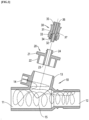
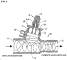
- FIG. 1 to FIG. 3 are views illustrating a ventilator medication injection structure according to an embodiment of the present disclosure, in which FIG. 1 is a view illustrating an external appearance of the ventilator medication injection structure, FIG. 2 is an exploded cross-sectional view in which elements of the ventilator medication injection structure are disassembled, and FIG. 3 is a cross-sectional view in which the elements are assembled.
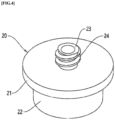
- FIG. 4 is a view illustrating a cover in the ventilator medication injection structure according to an embodiment of the present disclosure.
- FIG. 1 to FIG. 3 are views illustrating a ventilator medication injection structure according to an embodiment of the present disclosure, in which FIG. 1 is a view illustrating an external appearance of the ventilator medication injection structure, FIG. 2 is an exploded cross-sectional view in which elements of the ventilator medication injection structure are disassembled, and FIG. 3 is a cross-sectional view in which the elements are assembled.
- FIG. 4 is a view illustrating a cover in the ventilator medication injection structure according to an embodiment of the present disclosure.
- a ventilator medication injection structure may include a T-tube 10, a cover 20, and a packing closure 30.
- a tube body extends from an inlet 11 to an outlet 12, and a branch tube 13 is formed on one side of the tube body.
- a first tube body 22 is formed below a flange 21, and a second tube body 23 is formed inside the first tube body 22 such that the second tube body 23 penetrates the flange 21.
- a male screw 24 is formed on an outer peripheral surface of the second tube body 23.
- the first tube body 22 is fitted and assembled to the branch tube 13.
- a third tube body 32 is formed at a center of a body 31 such that the third tube body 32 is fitted inside the second tube body 23.
- a fourth tube body 33 is formed on an outside of the third tube body 32, and a female screw 34 is formed on the fourth tube body 33. As illustrated in FIG. 3 , the female screw 34 is fastened to the male screw 24.
- a pocket 35 is formed inside the body 31, and the pocket 35 may be densely filled with a packing 36.
- the packing 36 has elasticity. More specifically, the packing 36 may be formed of soft rubber. Accordingly, when a syringe needle pierces the packing 36, the syringe needle may penetrate the packing 36. Furthermore, when the syringe needle is pulled out, a piercing made by the syringe needle is immediately filled by the elasticity of the packing 36.
- Medication may be injected inside the T-tube 10 with a syringe by piercing the packing 36 with the syringe needle and passing the syringe needle through the third tube body 32.
- medication is capable of being injected into the T-tube 10 while a syringe needle is inserted into the packing 36, and the packing 36 is configured such that a space through which the syringe needle was passed is blocked when the syringe needle is removed from the packing 36, so that an inner portion of the T-tube 10 is capable of being fundamentally prevented from being exposed.
- the exposure of the inner portion of the T-tube 10 that serves as a medication case may be minimized or the medication case may be fundamentally blocked from being exposed, so that contamination of the medication case is prevented. Furthermore, a patient can live in a more strictly clean environment.
- an entire section of the tube connected from the ventilator to a mask or a mouthpiece may be strictly prevented from being exposed to the outside.
- the first tube body 22 may be provided in a tapered shape having a narrow lower side, and may be formed of a material having elasticity. Accordingly, as illustrated in FIG. 2 and FIG. 3 , when the ventilator medication injection structure in a disassembled state is assembled, the cover 20 is capable of being fitted and assembled in a straight direction without rotating the cover 20.
- the first tube body 22 is provided in the tapered shape, the first tube body 22 is easily assembled due to a large diameter difference at the beginning of assembly when the first tube body 22 is inserted into the branch tube 13, and the first tube body 22 may be assembled more and more tightly as the assembly progresses.
- the first tube body 22 has an elastic property, so that the first tube body 22 is in close contact with an entire of inner peripheral surface of the branch tube 13, so that contaminants from the outside may be fundamentally prevented from being introduced into the inner portion of the T-tube 10.
- a power connector 14 to which an external power source is capable of being connected is disposed on one side of the T-tube 10.
- a heating wire 15 may be disposed inside the T-tube 10, the heating wire 15 may generate heat by being connected to the external power source, and air conditioned as described above may be heated by the heat.
- the ventilator medication injection structure even when the temperature of conditioned air to be provided to a patient is low, the conditioned air is capable of being reheated, and the patient can always breathe the conditioned air at an appropriate temperature.
- a ventilator medication injection structure may be used for including medication in conditioned air and for heating the conditioned air when the conditioned air that is conditioned from a ventilator is provided to a patient.
Landscapes
- Health & Medical Sciences (AREA)
- Heart & Thoracic Surgery (AREA)
- Life Sciences & Earth Sciences (AREA)
- Engineering & Computer Science (AREA)
- Anesthesiology (AREA)
- Biomedical Technology (AREA)
- Veterinary Medicine (AREA)
- Hematology (AREA)
- Public Health (AREA)
- Animal Behavior & Ethology (AREA)
- General Health & Medical Sciences (AREA)
- Pulmonology (AREA)
- Emergency Medicine (AREA)
- Infusion, Injection, And Reservoir Apparatuses (AREA)
- Respiratory Apparatuses And Protective Means (AREA)
Claims (3)
- Arzneimittelinjektionsstruktur für eine Beatmungsvorrichtung, die Folgendes umfasst:ein T-Rohr (10), das einen Rohrkörper aufweist, der sich von einem Einlass (11) zu einem Auslass (12) erstreckt, wobei auf einer Seite des Rohrkörpers ein Abzweigrohr (13) gebildet ist;eine Abdeckung (20), die einen ersten Rohrkörper (22), der unter einem Flansch (21) gebildet ist, einen zweiten Rohrkörper (23), der im Inneren des ersten Rohrkörpers (22) gebildet ist, derart, dass der zweite Rohrkörper (23) den Flansch (21) durchdringt, und ein Außengewinde (24), das auf einer Außenumfangsfläche des zweiten Rohrkörpers (23) gebildet ist, aufweist; undeinen Dichtungsverschluss (30), der einen dritten Rohrkörper (32), der in einer Mitte eines Körpers (31) gebildet ist, derart, dass der dritte Rohrkörper (32) im Inneren des zweiten Rohrkörpers (23) eingepasst ist, einen vierten Rohrkörper (33), der auf einer Außenseite des dritten Rohrkörpers (32) gebildet ist, ein Innengewinde (34) , das auf dem vierten Rohrkörper (33) gebildet ist und am Außengewinde (24) befestigt wird, und eine Dichtung (36), die eine Elastizität aufweist und die im Inneren des Körpers (31) angeordnet ist, aufweist,wobei der erste Rohrkörper (22) am Abzweigrohr (13) eingepasst und angebracht ist und Arzneimittel mit einer Spritze in das Innere des T-Rohrs (10) injiziert werden können, indem die Dichtung (36) mit einer Spritzennadel durchstochen wird und die Spritzennadel durch den dritten Rohrkörper (32) hindurchtritt.
- Arzneimittelinjektionsstruktur für eine Beatmungsvorrichtung nach Anspruch 1, wobei der erste Rohrkörper (22) in einer abgeschrägten Form mit einer schmalen unteren Seite vorgesehen ist und aus einem Material gebildet ist, das Elastizität aufweist.
- Arzneimittelinjektionsstruktur für eine Beatmungsvorrichtung nach Anspruch 1, wobei ein Stromanschluss (14), mit dem eine externe Stromquelle verbunden ist, auf einer Seite des T-Rohrs (10) angeordnet ist, ein Heizdraht (15) im Inneren des T-Rohrs (10) angeordnet ist und der Heizdraht (15) konfiguriert ist, mit der externen Stromquelle verbunden zu sein, und konfiguriert ist, aufbereitete Luft zu erwärmen.
Applications Claiming Priority (2)
| Application Number | Priority Date | Filing Date | Title |
|---|---|---|---|
| KR1020210053445A KR102361810B1 (ko) | 2021-04-26 | 2021-04-26 | 인공호흡기의 약물 주입 구조 |
| PCT/KR2022/004024 WO2022231133A1 (ko) | 2021-04-26 | 2022-03-23 | 인공호흡기의 약물 주입 구조 |
Publications (4)
| Publication Number | Publication Date |
|---|---|
| EP4292633A1 EP4292633A1 (de) | 2023-12-20 |
| EP4292633A4 EP4292633A4 (de) | 2024-08-14 |
| EP4292633B1 true EP4292633B1 (de) | 2025-06-04 |
| EP4292633C0 EP4292633C0 (de) | 2025-06-04 |
Family
ID=80254018
Family Applications (1)
| Application Number | Title | Priority Date | Filing Date |
|---|---|---|---|
| EP22795967.3A Active EP4292633B1 (de) | 2021-04-26 | 2022-03-23 | Struktur zur injektion von medikamenten in einem beatmungsgerät |
Country Status (7)
| Country | Link |
|---|---|
| US (1) | US20240226492A9 (de) |
| EP (1) | EP4292633B1 (de) |
| JP (1) | JP7572596B2 (de) |
| KR (1) | KR102361810B1 (de) |
| CN (1) | CN117015409B (de) |
| ES (1) | ES3035396T3 (de) |
| WO (1) | WO2022231133A1 (de) |
Families Citing this family (1)
| Publication number | Priority date | Publication date | Assignee | Title |
|---|---|---|---|---|
| KR102698781B1 (ko) * | 2022-03-04 | 2024-08-26 | 바디텍메드(주) | 인공호흡기용 약물 에어로졸 공급 장치 |
Family Cites Families (26)
| Publication number | Priority date | Publication date | Assignee | Title |
|---|---|---|---|---|
| US4445896A (en) * | 1982-03-18 | 1984-05-01 | Cook, Inc. | Catheter plug |
| IT1185857B (it) * | 1985-08-02 | 1987-11-18 | Erba Farmitalia | Dispositivo per collegare una estremita' di un tubicino di erogazione di un farmaco liquido ad un apparecchio per il collegamento di una siringa ad un flacone contenente il farmaco |
| US4953547A (en) * | 1989-01-26 | 1990-09-04 | Poole Jr Samuel E | Drug administering endotracheal respiration systems |
| US5181508A (en) * | 1989-01-26 | 1993-01-26 | Poole Jr Samuel E | Molded connector |
| US5207220A (en) * | 1989-12-12 | 1993-05-04 | Burroughs Wellcome Co. | Method for administering pharmaceuticals, including liquid surfactant, to the lungs |
| EP0758257B1 (de) * | 1994-05-06 | 2000-02-23 | Mark Brauner | Gerät zur intrapulmonaren therapie und medikamentenabgabe |
| US5701886A (en) * | 1995-08-07 | 1997-12-30 | Ryatt; Sadie | Treatment non-rebreather assembly and method for delivering oxygen and medication |
| US5947120A (en) * | 1997-05-05 | 1999-09-07 | Bailey; William A. | Medication administering apparatus for use with an endotracheal tube |
| US7600511B2 (en) * | 2001-11-01 | 2009-10-13 | Novartis Pharma Ag | Apparatus and methods for delivery of medicament to a respiratory system |
| ES2327935T3 (es) | 2003-11-17 | 2009-11-05 | Nektar Therapeutics | Introduccion de un aerosol en un circuito de un ventilador. |
| CN1956745B (zh) | 2004-04-20 | 2012-02-22 | 亚罗擎公司 | 用于压力辅助型呼吸系统的气雾剂输送装置 |
| US7191776B2 (en) * | 2004-05-10 | 2007-03-20 | Smiths Medical Asd, Inc. | Nebulizer breathing system |
| KR101237767B1 (ko) | 2004-08-31 | 2013-02-28 | 에디컨 엔도-서저리 인코포레이티드 | 의료용 이펙터 시스템 |
| JP5087539B2 (ja) * | 2005-05-18 | 2012-12-05 | ネクター セラピューティックス | 気管支内治療のためのバルブ、デバイス、および方法 |
| EP1924310B1 (de) * | 2005-08-23 | 2016-04-20 | Nektar Therapeutics | Selbstversiegelndes T-Stück und Ventil-T-Stück |
| EP2203155A1 (de) | 2007-09-25 | 2010-07-07 | Novartis Ag | Behandlung von lungenerkrankungen mit medikamenten in aerosolform wie vancomycin |
| US20090306545A1 (en) * | 2008-06-09 | 2009-12-10 | Mamdouh Elsakka | Bronchoalveolar lavage catheter assembly |
| US9272114B2 (en) * | 2012-06-18 | 2016-03-01 | Flexible Technologies, Inc. | Heated CPAP hose and fitting |
| KR101424934B1 (ko) * | 2013-07-22 | 2014-08-04 | 고려대학교 산학협력단 | 수액 세트용 분기관 |
| KR101459399B1 (ko) | 2014-01-23 | 2014-11-12 | 연세대학교 원주산학협력단 | 자동분사식 포터블 네블라이져 |
| EP3641867A4 (de) * | 2017-06-23 | 2021-01-20 | Fisher&Paykel Healthcare Limited | Konnektoren für atemhilfssysteme |
| KR20190030976A (ko) * | 2017-09-15 | 2019-03-25 | 박만식 | 인공호흡기용 호흡가스 가습장치 |
| KR102108120B1 (ko) * | 2018-01-10 | 2020-05-11 | 주식회사 폴리사이언텍 | 니들리스 커넥터 및 니들리스 커넥터의 셉텀 제작 방법 |
| CN210057135U (zh) * | 2018-12-28 | 2020-02-14 | 江苏华夏医疗器械有限公司 | 一种高洁净度的静脉延长使用三通阀 |
| KR102318976B1 (ko) * | 2019-06-17 | 2021-11-02 | 주식회사 소연메디칼 | 인공호흡기용 호흡관장치 |
| CN110575591A (zh) * | 2019-09-09 | 2019-12-17 | 浙江莱福医疗科技有限公司 | 一种呼吸管路接口及应用该呼吸管路接口的呼吸机 |
-
2021
- 2021-04-26 KR KR1020210053445A patent/KR102361810B1/ko active Active
-
2022
- 2022-03-23 ES ES22795967T patent/ES3035396T3/es active Active
- 2022-03-23 CN CN202280017760.6A patent/CN117015409B/zh active Active
- 2022-03-23 EP EP22795967.3A patent/EP4292633B1/de active Active
- 2022-03-23 JP JP2023553303A patent/JP7572596B2/ja active Active
- 2022-03-23 WO PCT/KR2022/004024 patent/WO2022231133A1/ko not_active Ceased
- 2022-03-23 US US18/548,105 patent/US20240226492A9/en active Pending
Also Published As
| Publication number | Publication date |
|---|---|
| ES3035396T3 (en) | 2025-09-02 |
| JP2024527177A (ja) | 2024-07-22 |
| JP7572596B2 (ja) | 2024-10-24 |
| CN117015409A (zh) | 2023-11-07 |
| EP4292633A4 (de) | 2024-08-14 |
| KR102361810B1 (ko) | 2022-02-14 |
| WO2022231133A1 (ko) | 2022-11-03 |
| US20240131293A1 (en) | 2024-04-25 |
| EP4292633C0 (de) | 2025-06-04 |
| CN117015409B (zh) | 2026-04-10 |
| US20240226492A9 (en) | 2024-07-11 |
| EP4292633A1 (de) | 2023-12-20 |
Similar Documents
| Publication | Publication Date | Title |
|---|---|---|
| US20240390632A1 (en) | Connectors for respiratory assistance systems | |
| KR101615096B1 (ko) | 호흡기 액세스 조립체 | |
| US11998700B2 (en) | Ventilation assembly including respiratory device and mechanical ventilator | |
| US7549419B2 (en) | Heat and moisture exchanger adaptor for closed suction catheter assembly and system containing the same | |
| US6976488B2 (en) | Medication bypass heat and moisture exchange unit | |
| US5357946A (en) | Ventilator manifold with accessory access port and adaptors therefore | |
| RU2556520C2 (ru) | Конструктивные улучшения дыхательного приспособления | |
| US12257389B2 (en) | Dual-connector wye piece | |
| CN104968386A (zh) | 多功能氧气面罩 | |
| JP2005525145A (ja) | 医療用コネクタ | |
| US20150352303A1 (en) | Device having manual resuscitation and suction capabilities | |
| US6237597B1 (en) | Endotracheal medication port adapter | |
| US11253670B1 (en) | Respiratory isolation and/or treatment devices and methods of using the same | |
| EP4292633A1 (de) | Struktur zur injektion von medikamenten in einem beatmungsgerät | |
| EP2621574B1 (de) | Umspritzter dichtungsring eines verteilers | |
| CA2819447A1 (en) | Nebulizer for use in mechanical respiratory ventilation therapy | |
| CN203989325U (zh) | 医用雾化器 | |
| US20250073132A1 (en) | Pacifier | |
| TR2023013178A2 (tr) | Anatomi̇k uyumlu i̇leti̇ci̇ |
Legal Events
| Date | Code | Title | Description |
|---|---|---|---|
| STAA | Information on the status of an ep patent application or granted ep patent |
Free format text: STATUS: THE INTERNATIONAL PUBLICATION HAS BEEN MADE |
|
| PUAI | Public reference made under article 153(3) epc to a published international application that has entered the european phase |
Free format text: ORIGINAL CODE: 0009012 |
|
| STAA | Information on the status of an ep patent application or granted ep patent |
Free format text: STATUS: REQUEST FOR EXAMINATION WAS MADE |
|
| 17P | Request for examination filed |
Effective date: 20230828 |
|
| AK | Designated contracting states |
Kind code of ref document: A1 Designated state(s): AL AT BE BG CH CY CZ DE DK EE ES FI FR GB GR HR HU IE IS IT LI LT LU LV MC MK MT NL NO PL PT RO RS SE SI SK SM TR |
|
| DAV | Request for validation of the european patent (deleted) | ||
| DAX | Request for extension of the european patent (deleted) | ||
| A4 | Supplementary search report drawn up and despatched |
Effective date: 20240716 |
|
| RIC1 | Information provided on ipc code assigned before grant |
Ipc: A61M 16/08 20060101ALI20240710BHEP Ipc: A61M 16/10 20060101ALI20240710BHEP Ipc: A61M 16/12 20060101AFI20240710BHEP |
|
| REG | Reference to a national code |
Ref country code: DE Ref legal event code: R079 Free format text: PREVIOUS MAIN CLASS: A61M0016120000 Ipc: A61M0016080000 Ref country code: DE Ref legal event code: R079 Ref document number: 602022015632 Country of ref document: DE Free format text: PREVIOUS MAIN CLASS: A61M0016120000 Ipc: A61M0016080000 |
|
| GRAP | Despatch of communication of intention to grant a patent |
Free format text: ORIGINAL CODE: EPIDOSNIGR1 |
|
| STAA | Information on the status of an ep patent application or granted ep patent |
Free format text: STATUS: GRANT OF PATENT IS INTENDED |
|
| RIC1 | Information provided on ipc code assigned before grant |
Ipc: A61M 16/14 20060101ALI20241218BHEP Ipc: A61M 16/10 20060101ALI20241218BHEP Ipc: A61M 16/08 20060101AFI20241218BHEP |
|
| INTG | Intention to grant announced |
Effective date: 20250114 |
|
| GRAS | Grant fee paid |
Free format text: ORIGINAL CODE: EPIDOSNIGR3 |
|
| GRAA | (expected) grant |
Free format text: ORIGINAL CODE: 0009210 |
|
| STAA | Information on the status of an ep patent application or granted ep patent |
Free format text: STATUS: THE PATENT HAS BEEN GRANTED |
|
| AK | Designated contracting states |
Kind code of ref document: B1 Designated state(s): AL AT BE BG CH CY CZ DE DK EE ES FI FR GB GR HR HU IE IS IT LI LT LU LV MC MK MT NL NO PL PT RO RS SE SI SK SM TR |
|
| REG | Reference to a national code |
Ref country code: GB Ref legal event code: FG4D |
|
| REG | Reference to a national code |
Ref country code: CH Ref legal event code: EP |
|
| REG | Reference to a national code |
Ref country code: DE Ref legal event code: R096 Ref document number: 602022015632 Country of ref document: DE |
|
| REG | Reference to a national code |
Ref country code: IE Ref legal event code: FG4D |
|
| U01 | Request for unitary effect filed |
Effective date: 20250630 |
|
| U07 | Unitary effect registered |
Designated state(s): AT BE BG DE DK EE FI FR IT LT LU LV MT NL PT RO SE SI Effective date: 20250704 |
|
| REG | Reference to a national code |
Ref country code: ES Ref legal event code: FG2A Ref document number: 3035396 Country of ref document: ES Kind code of ref document: T3 Effective date: 20250902 |
|
| PG25 | Lapsed in a contracting state [announced via postgrant information from national office to epo] |
Ref country code: NO Free format text: LAPSE BECAUSE OF FAILURE TO SUBMIT A TRANSLATION OF THE DESCRIPTION OR TO PAY THE FEE WITHIN THE PRESCRIBED TIME-LIMIT Effective date: 20250904 Ref country code: GR Free format text: LAPSE BECAUSE OF FAILURE TO SUBMIT A TRANSLATION OF THE DESCRIPTION OR TO PAY THE FEE WITHIN THE PRESCRIBED TIME-LIMIT Effective date: 20250905 |
|
| PG25 | Lapsed in a contracting state [announced via postgrant information from national office to epo] |
Ref country code: PL Free format text: LAPSE BECAUSE OF FAILURE TO SUBMIT A TRANSLATION OF THE DESCRIPTION OR TO PAY THE FEE WITHIN THE PRESCRIBED TIME-LIMIT Effective date: 20250604 |
|
| PG25 | Lapsed in a contracting state [announced via postgrant information from national office to epo] |
Ref country code: HR Free format text: LAPSE BECAUSE OF FAILURE TO SUBMIT A TRANSLATION OF THE DESCRIPTION OR TO PAY THE FEE WITHIN THE PRESCRIBED TIME-LIMIT Effective date: 20250604 |
|
| PG25 | Lapsed in a contracting state [announced via postgrant information from national office to epo] |
Ref country code: RS Free format text: LAPSE BECAUSE OF FAILURE TO SUBMIT A TRANSLATION OF THE DESCRIPTION OR TO PAY THE FEE WITHIN THE PRESCRIBED TIME-LIMIT Effective date: 20250904 |
|
| PG25 | Lapsed in a contracting state [announced via postgrant information from national office to epo] |
Ref country code: IS Free format text: LAPSE BECAUSE OF FAILURE TO SUBMIT A TRANSLATION OF THE DESCRIPTION OR TO PAY THE FEE WITHIN THE PRESCRIBED TIME-LIMIT Effective date: 20251004 |
|
| PG25 | Lapsed in a contracting state [announced via postgrant information from national office to epo] |
Ref country code: SM Free format text: LAPSE BECAUSE OF FAILURE TO SUBMIT A TRANSLATION OF THE DESCRIPTION OR TO PAY THE FEE WITHIN THE PRESCRIBED TIME-LIMIT Effective date: 20250604 |
|
| PG25 | Lapsed in a contracting state [announced via postgrant information from national office to epo] |
Ref country code: CZ Free format text: LAPSE BECAUSE OF FAILURE TO SUBMIT A TRANSLATION OF THE DESCRIPTION OR TO PAY THE FEE WITHIN THE PRESCRIBED TIME-LIMIT Effective date: 20250604 |
|
| PG25 | Lapsed in a contracting state [announced via postgrant information from national office to epo] |
Ref country code: SK Free format text: LAPSE BECAUSE OF FAILURE TO SUBMIT A TRANSLATION OF THE DESCRIPTION OR TO PAY THE FEE WITHIN THE PRESCRIBED TIME-LIMIT Effective date: 20250604 |
|
| PGFP | Annual fee paid to national office [announced via postgrant information from national office to epo] |
Ref country code: GB Payment date: 20260312 Year of fee payment: 5 |
|
| PLBE | No opposition filed within time limit |
Free format text: ORIGINAL CODE: 0009261 |
|
| STAA | Information on the status of an ep patent application or granted ep patent |
Free format text: STATUS: NO OPPOSITION FILED WITHIN TIME LIMIT |
|
| REG | Reference to a national code |
Ref country code: CH Ref legal event code: L10 Free format text: ST27 STATUS EVENT CODE: U-0-0-L10-L00 (AS PROVIDED BY THE NATIONAL OFFICE) Effective date: 20260416 |
|
| U20 | Renewal fee for the european patent with unitary effect paid |
Year of fee payment: 5 Effective date: 20260319 |
|
| 26N | No opposition filed |
Effective date: 20260305 |