EP4290324B1 - Leit- und steuersystem und verfahren für automatische offline-reinigung von kufen - Google Patents
Leit- und steuersystem und verfahren für automatische offline-reinigung von kufen Download PDFInfo
- Publication number
- EP4290324B1 EP4290324B1 EP23159708.9A EP23159708A EP4290324B1 EP 4290324 B1 EP4290324 B1 EP 4290324B1 EP 23159708 A EP23159708 A EP 23159708A EP 4290324 B1 EP4290324 B1 EP 4290324B1
- Authority
- EP
- European Patent Office
- Prior art keywords
- skid
- module
- offline
- control module
- detection
- Prior art date
- Legal status (The legal status is an assumption and is not a legal conclusion. Google has not performed a legal analysis and makes no representation as to the accuracy of the status listed.)
- Active
Links
Images

Classifications
-
- G—PHYSICS
- G05—CONTROLLING; REGULATING
- G05B—CONTROL OR REGULATING SYSTEMS IN GENERAL; FUNCTIONAL ELEMENTS OF SUCH SYSTEMS; MONITORING OR TESTING ARRANGEMENTS FOR SUCH SYSTEMS OR ELEMENTS
- G05B19/00—Program-control systems
- G05B19/02—Program-control systems electric
- G05B19/04—Program control other than numerical control, i.e. in sequence controllers or logic controllers
- G05B19/05—Programmable logic controllers, e.g. simulating logic interconnections of signals according to ladder diagrams or function charts
- G05B19/054—Input/output
-
- G—PHYSICS
- G05—CONTROLLING; REGULATING
- G05B—CONTROL OR REGULATING SYSTEMS IN GENERAL; FUNCTIONAL ELEMENTS OF SUCH SYSTEMS; MONITORING OR TESTING ARRANGEMENTS FOR SUCH SYSTEMS OR ELEMENTS
- G05B19/00—Program-control systems
- G05B19/02—Program-control systems electric
- G05B19/418—Total factory control, i.e. centrally controlling a plurality of machines, e.g. direct or distributed numerical control [DNC], flexible manufacturing systems [FMS], integrated manufacturing systems [IMS] or computer integrated manufacturing [CIM]
- G05B19/41875—Total factory control, i.e. centrally controlling a plurality of machines, e.g. direct or distributed numerical control [DNC], flexible manufacturing systems [FMS], integrated manufacturing systems [IMS] or computer integrated manufacturing [CIM] characterised by quality surveillance of production
-
- G—PHYSICS
- G05—CONTROLLING; REGULATING
- G05B—CONTROL OR REGULATING SYSTEMS IN GENERAL; FUNCTIONAL ELEMENTS OF SUCH SYSTEMS; MONITORING OR TESTING ARRANGEMENTS FOR SUCH SYSTEMS OR ELEMENTS
- G05B2219/00—Program-control systems
- G05B2219/10—Plc systems
- G05B2219/11—Plc I-O input output
- G05B2219/1103—Special, intelligent I-O processor, also plc can only access via processor
-
- Y—GENERAL TAGGING OF NEW TECHNOLOGICAL DEVELOPMENTS; GENERAL TAGGING OF CROSS-SECTIONAL TECHNOLOGIES SPANNING OVER SEVERAL SECTIONS OF THE IPC; TECHNICAL SUBJECTS COVERED BY FORMER USPC CROSS-REFERENCE ART COLLECTIONS [XRACs] AND DIGESTS
- Y02—TECHNOLOGIES OR APPLICATIONS FOR MITIGATION OR ADAPTATION AGAINST CLIMATE CHANGE
- Y02P—CLIMATE CHANGE MITIGATION TECHNOLOGIES IN THE PRODUCTION OR PROCESSING OF GOODS
- Y02P90/00—Enabling technologies with a potential contribution to greenhouse gas [GHG] emissions mitigation
- Y02P90/02—Total factory control, e.g. smart factories, flexible manufacturing systems [FMS] or integrated manufacturing systems [IMS]
Definitions
- the present disclosure belongs to the technical field of automobile production, and in particular, relates to an automatic skid offline-cleaning guidance and control system and method.
- skids with serious paint accumulation and adhesion need to be cleaned offline.
- manual inspection is mainly used to determine whether a skid needs to be taken offline, and the skid will be taken offline manually.
- long-term in the painting and spraying sites is detrimental to the health of people, resulting in high labor costs, and any omissions in the inspection may lead to incomplete cleaning and eventually cause losses by shutdown of the production line.
- an automatic skid offline-cleaning guidance and control system includes a PLC control module, a skid position tracking and paint fouling condition monitoring subsystem, a skid offline control subsystem, a skid detection subsystem, and a human-computer interaction interface, the PLC control module being connected to the skid position tracking and paint fouling condition monitoring subsystem, the skid offline control subsystem, the skid detection subsystem, and the human-computer interaction interface;
- the skid position tracking and paint fouling condition monitoring subsystem includes a skid paint fouling detection and position monitoring module, a skid information data storage module, and a communication module, the skid paint fouling detection and position monitoring module being connected to the skid information data storage module and the communication module;
- the skid offline control subsystem includes an input/output module, a first enabling control module, a first action control module, a skid offline control frequency converter, a skid offline control motor, a second enabling control module, a second action control module, a skid rotation control frequency converter, and a skid rotation control motor;
- the skid rotation control frequency converter being connected to the skid rotation control motor, the second enabling control module and the second action control module;
- the skid offline control frequency converter being connected to the skid offline control motor, the first enabling control module and the first action control module;
- the first enabling control module, the first action control module, the second enabling control module and the second action control module being connected to the input/output module, and the input/output module being connected to the PLC control module;
- the skid detection subsystem includes a skid path selection in-place detection switch, a skid offline in-place detection switch, a skid passing-point count detection module, an offline in-place skid information detection module, a skid information writing module, a skid rotation in-place detection switch, and a remote input/output module; the remote input/output module being connected to the skid path selection in-place detection switch, the skid offline in-place detection switch, the skid passing-point count detection module, the offline in-place skid information detection module, the skid information writing module, the skid rotation in-place detection switch and the PLC control module; wherein
- the communication module is an Ethernet communication module.
- each of the first enabling control module, the first action control module, the second enabling control module and the second action control module is a relay.
- each of the skid passing-point count detection module, the offline in-position skid information detection module and the skid information writing module is an RFID module.
- an automatic skid offline-cleaning guidance and control method using the automatic skid offline-cleaning guidance and control system according to the present disclosure, includes the following steps of:
- step S1 specifically includes:
- step S2 specifically includes:
- the present disclosure has the following advantages.
- the disclosed system and method is capable of automatically monitoring paint fouling on skids, and automatically guiding and controlling a skid that has reached the criterion for cleaning to be taken offline. Besides, the costs reduced, and manual inspection can be eliminated.
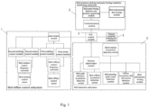
- skid offline control subsystem 1) skid position tracking and paint fouling condition monitoring subsystem; 3) a PLC control module; 4) human-computer interaction interface; and 5) skid detection subsystem.
- an automatic skid offline-cleaning guidance and control system includes a PLC control module 3, a skid position tracking and paint fouling condition monitoring subsystem 2, a skid offline control subsystem 1, a skid detection subsystem 5, and a human-computer interaction interface 4, the PLC control module 3 being connected to the skid position tracking and paint fouling condition monitoring subsystem 2, the skid offline control subsystem 1, the skid detection subsystem 5, and the human-computer interaction interface 4.
- the PLC control module 3 is configured to read a serial number of a skid and identify a position of the skid.
- the skid position tracking and paint fouling condition monitoring subsystem 2 is configured to acquire the serial number of the skid and information about the position of the skid from the PLC control module 3, detect a paint fouling condition of the skid, and send a skid cleaning request to the PLC control module 3 when determining that the skid needs to be cleaned.
- the PLC control module 3 sends a skid cleaning instruction to the skid offline control subsystem 1 based on the skid cleaning request, and the skid offline control subsystem 1 performs an offline operation on the skid based on the skid cleaning instruction.
- the human-computer interaction interface 4 is configured to display hardware status of the whole guidance and control system, information about the paint fouling condition of the skid, and information about the position of the skid.
- the skid position tracking and paint fouling condition monitoring subsystem 2 includes a skid paint fouling detection and position monitoring module, a skid information data storage module, and a communication module, the skid paint fouling detection and position monitoring module being connected to the skid information data storage module and the communication module.
- the skid paint fouling detection and position monitoring module is configured to acquire the serial number of the skid and information about the position of the skid from the PLC control module 3 to monitor a paint fouling condition of the skid and detect paint fouling on the skid, and send a skid cleaning request instruction to the PLC control module 3.
- the skid information data storage module is configured to record the information about the position of the skid and a state of the skid, the state of the skid including an offline state and an online state;
- the communication module is configured to communicate the information about the position of the skid, information about the state of the skid, and a cleaning request label.
- the skid offline control subsystem 1 includes an input/output module, a first enabling control module, a first action control module, a skid offline control frequency converter, a skid offline control motor, a second enabling control module, a second action control module, a skid rotation control frequency converter, and a skid rotation control motor; the skid rotation control frequency converter being connected to the skid rotation control motor, the second enabling control module and the second action control module; the skid offline control frequency converter being connected to the skid offline control motor, the first enabling control module and the first action control module; the first enabling control module, the first action control module, the second enabling control module and the second action control module being connected to the input/output module, and the input/output module being connected to the PLC control module 3.
- the skid rotation control frequency converter is configured to control the skid rotation control motor to perform a rotation action upon reception of a rotation control instruction sent by the PLC control module 3 through the second enabling control module and the second action control module.
- the skid offline control frequency converter is configured to control the skid offline control motor to perform an offline action upon reception of an offline control instruction sent by the PLC control module 3 through the first enabling control module and the first action control module.
- the input-output module is configured for in-cabinet IO signal communication.
- the skid detection subsystem includes a skid path selection in-position detection switch, a skid offline in-position detection switch, a skid passing-point count detection module, an offline in-position skid information detection module, a skid information writing module, a skid rotation in-position detection switch, and a remote input/output module; the remote input/output module being connected to the skid path selection in-position detection switch, the skid offline in-position detection switch, the skid passing-point count detection module, the offline in-position skid information detection module, the skid information writing module, the skid rotation in-position detection switch and the PLC control module 3.
- the offline in-position skid information detection module is configured to detect the position of the skid, and acquire the serial number of the skid and information about the cleaning request.
- the skid path selection in-position detection switch, the skid rotation in-position detection switch and the skid offline in-position detection switch are configured to detect the position of the skid.
- the skid passing-point count detection module is configured to detect the position of the skid and write a cleaning request flag.
- the skid information writing module is configured to change the cleaning request flag.
- the remote input/output module is configured for distributed IO signal communication.
- the system is capable of automatically monitoring paint fouling on skids, and automatically guiding and controlling a skid that has reached the criterion for cleaning to be taken offline.
- the communication module is an Ethernet communication module.
- each of the first enabling control module, the first action control module, the second enabling control module and the second action control module is a relay.
- each of the skid passing-point count detection module, the offline in-position skid information detection module and the skid information writing module is an RFID module.
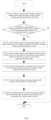
- an automatic skid offline-cleaning guidance and control method using the automatic skid offline-cleaning guidance and control system according to the embodiments of the present disclosure, includes the following steps of:
- the step S1 specifically includes:
- the step S2 specifically includes:
- the method is capable of automatically monitoring paint fouling on skids, and automatically guiding and controlling a skid that has reached the criterion for cleaning to be taken offline.
Landscapes
- Engineering & Computer Science (AREA)
- Physics & Mathematics (AREA)
- General Physics & Mathematics (AREA)
- Automation & Control Theory (AREA)
- General Engineering & Computer Science (AREA)
- Manufacturing & Machinery (AREA)
- Quality & Reliability (AREA)
- Cleaning In General (AREA)
- Control Of Conveyors (AREA)
- General Factory Administration (AREA)
Claims (10)
- Leit- und Steuersystem für automatische Offline-Reinigung von Kufen, umfassend: ein PLC-Steuermodul (3), ein Teilsystem (2) zur Kufenpositionsbestimmung und Überwachung von Farbverschmutzungsbedingung, ein Offline-Kufensteuerteilsystem (1), ein Kufendetektionsteilsystem (5) und eine Mensch-Computer-Interaktionsschnittstelle (4), wobei das PLC-Steuermodul (3) mit dem Teilsystem (2) zur Kufenpositionsbestimmung und Überwachung von Farbverschmutzungsbedingung, dem Offline-Kufensteuerteilsystem (1), dem Kufendetektionsteilsystem (5) und der Mensch-Computer-Interaktionsschnittstelle (4) verbunden ist;
dadurch gekennzeichnet, dassdas PLC-Steuermodul (3) dazu konfiguriert ist, eine Seriennummer einer Kufe abzulesen und eine Position der Kufe zu identifizieren;das Teilsystem (2) zur Kufenpositionsbestimmung und Überwachung von Farbverschmutzungsbedingung dazu konfiguriert ist, die Seriennummer der Kufe und Informationen über die Position der Kufe von dem PLC-Steuermodul (3) zu erfassen, eine Farbverschmutzungsbedingung der Kufe zu detektieren und eine Kufenreinigungsanforderung an das PLC-Steuermodul (3) zu senden, wenn bestimmt wird, dass die Kufe gereinigt werden muss;das PLC-Steuermodul (3) eine Kufenreinigungsanweisung an das Offline-Kufensteuerteilsystem (1) auf Grundlage der Kufenreinigungsanforderung sendet und das Offline-Kufensteuerteilsystem (1) einen Offline-Betreib der Kufe auf Grundlage der Kufenreinigungsanweisung durchführt;die Mensch-Computer-Interaktionsschnittstelle (4) dazu konfiguriert ist, Hardwarestatus des gesamten Leit- und Steuersystems, Informationen über die Farbverschmutzungsbedingung der Kufe und Informationen über die Position der Kufe anzuzeigen. - Leit- und Steuersystem für automatische Offline-Reinigung von Kufen nach Anspruch 1, wobei das Teilsystem (2) zur Kufenpositionsbestimmung und Überwachung von Farbverschmutzungsbedingung ein Modul zur Überwachung von Farbverschmutzungsdetektion und Position der Kufe, ein Kufeninformationsdatenspeichermodul und ein Kommunikationsmodul umfasst, wobei das Modul zur Farbverschmutzungsdetektion und Überwachung der Position der Kufe mit dem Kufeninformationsdatenspeichermodul und dem Kommunikationsmodul verbunden ist; wobeidas Modul zur Farbverschmutzungsdetektion und Überwachung der Position der Kufe dazu konfiguriert ist, die Seriennummer der Kufe und Informationen über die Position der Kufe von dem PLC-Steuermodul (3) zu erfassen, um eine Farbverschmutzungsbedingung der Kufe zu überwachen und eine Farbverschmutzung an der Kufe zu detektieren, und eine Kufenreinigungsanforderungsanweisung an das PLC-Steuermodul (3) zu senden;das Kufeninformationsdatenspeichermodul dazu konfiguriert ist, die Informationen über die Position der Kufe und einen Zustand der Kufe aufzuzeichnen, wobei der Zustand der Kufe einen Offline-Zustand und einen Online-Zustand beinhaltet;das Kommunikationsmodul dazu konfiguriert ist, die Informationen über die Position der Kufe, Informationen über den Zustand der Kufe und eine Reinigungsanforderungsbezeichnung zu kommunizieren.
- Leit- und Steuersystem für automatische Offline-Reinigung von Kufen nach Anspruch 2, wobei das Offline-Kufensteuerteilsystem (1) ein Eingangs-/Ausgangsmodul, ein erstes Aktivierungssteuermodul, ein erstes Aktionssteuermodul, einen Offline-Kufensteuerfrequenzwandler, einen Offline-Kufensteuermotor, ein zweites Aktivierungssteuermodul, ein zweites Aktionssteuermodul, einen Kufenrotationssteuerfrequenzwandler und einen Kufenrotationssteuermotor umfasst; wobei der Kufenrotationssteuerfrequenzwandler mit dem Kufenrotationssteuermotor, dem zweiten Aktivierungssteuermodul und dem zweiten Aktionssteuermodul verbunden ist; wobei der Offline-Kufensteuerfrequenzwandler mit dem Offline-Kufensteuermotor, dem ersten Aktivierungssteuermodul und dem ersten Aktionssteuermodul verbunden ist; wobei das erste Aktivierungssteuermodul, das erste Aktionssteuermodul, das zweite Aktivierungssteuermodul und das zweite Aktionssteuermodul mit dem Eingangs-/Ausgangsmodul verbunden ist und das Eingangs-/Ausgangsmodul mit dem PLC-Steuermodul (3) verbunden ist; wobeider Kufenrotationssteuerfrequenzwandler dazu konfiguriert ist, den Kufenrotationssteuermotor zu steuern, um einen Rotationsvorgang bei Empfang einer Rotationssteueranweisung, die von dem PLC-Steuermodul (3) durch das zweite Aktivierungssteuermodul und das zweite Aktionssteuermodul gesendet wird, durchzuführen;der Offline-Kufensteuerfrequenzwandler dazu konfiguriert ist, den Offline-Kufensteuermotor zu steuern, um einen Offline-Vorgang bei Empfang einer Offline-Steueranweisung, die von dem PLC-Steuermodul (3) durch das erste Aktivierungssteuermodul und das erste Aktionssteuermodul gesendet wird, durchzuführen;das Eingangs-/Ausgangsmodul zur integrierten EA-Signalkommunikation konfiguriert ist.
- Leit- und Steuersystem für automatische Offline-Reinigung von Kufen nach Anspruch 3, wobei das Kufendetektionsteilsystem einen Schalter zur Detektion der korrekten Position der Kufenpfadauswahl, einen Schalter zur Offline-Detektion der korrekten Position der Kufe, ein Modul zur Detektion der Passierpunktanzahl der Kufe, ein Modul zur Offline-Detektion der Informationen zur korrekten Position der Kufe, ein Kufeninformationsschreibmodul, einen Schalter zur Detektion der korrekten Position der Kufenrotation und ein entferntes Eingangs-/Ausgangsmodul umfasst; wobei das entfernte Eingangs-/Ausgangsmodul mit dem Schalter zur Detektion der korrekten Position der Kufenpfadauswahl, dem Schalter zur Offline-Detektion der korrekten Position der Kufe, dem Modul zur Detektion der Passierpunktanzahl der Kufe, dem Modul zur Offline-Detektion der Informationen zur korrekten Position der Kufe, dem Kufeninformationsschreibmodul, dem Schalter zur Detektion der korrekten Position der Kufenrotation und dem PLC-Steuermodul (3) verbunden ist; wobeidas Modul zur Offline-Detektion der Informationen zur korrekten Position der Kufe dazu konfiguriert ist, die Position der Kufe zu detektieren und die Seriennummer der Kufe und Informationen über die Reinigungsanforderung zu erfassen;der Schalter zur Detektion der korrekten Position der Kufenpfadauswahl, der Schalter zur Detektion der korrekten Information der Kufenrotation und der Schalter zur Offline-Detektion der korrekten Position der Kufe dazu konfiguriert sind, die Position der Kufe zu detektieren;das Modul zur Detektion der Passierpunktanzahl der Kufe dazu konfiguriert ist, die Position der Kufe zu detektieren und eine Reinigungsanforderungsmarkierung zu schreiben;das Kufeninformationsschreibmodul dazu konfiguriert ist, die Reinigungsanforderungsmarkierung zu verändern;das entfernte Eingangs-/Ausgangsmodul zur verteilten EA-Signalkommunikation konfiguriert ist.
- Leit- und Steuersystem für automatische Offline-Reinigung von Kufen nach einem der Ansprüche 2 bis 4, wobei das Kommunikationsmodul ein Ethernet-Kommunikationsmodul ist.
- Leit- und Steuersystem für automatische Offline-Reinigung von Kufen nach Anspruch 3 oder 4, wobei jedes von dem ersten Aktivierungssteuermodul, dem ersten Aktionssteuermodul, dem zweiten Aktivierungssteuermodul und dem zweiten Aktionssteuermodul ein Relais ist.
- Leit- und Steuersystem für automatische Offline-Reinigung von Kufen nach Anspruch 4, wobei jedes von dem Modul zur Detektion der Passierpunktanzahl der Kufe, dem Modul zur Offline-Detektion der Informationen zur korrekten Position der Kufe und dem Kufeninformationsschreibmodul ein RFID-Modul ist.
- Leit- und Steuerverfahren für automatische Offline-Reinigung von Kufen, gekennzeichnet durch die Verwendung des Leit- und Steuersystems für automatische Offline-Reinigung von Kufen nach einem der Ansprüche 4 bis 7, wobei das Verfahren die folgenden Schritte umfasst:S1: Überwachung der Farbverschmutzungsbedingung:
wenn ein Kufendetektionsteilsystem (5) eine passierende Kufe erfasst, liest ein Teilsystem (2) zur Kufenpositionsbestimmung und Überwachung von Farbverschmutzungsbedingung eine Seriennummer der Kufe durch ein PLC-Steuermodul (3) ab; erfasst das Teilsystem (2) zur Kufenpositionsbestimmung und Überwachung von Farbverschmutzungsbedingung die Seriennummer der Kufe und Informationen über eine Position der Kufe von dem PLC-Steuermodul (3), detektiert es eine Farbverschmutzungsbedingung der Kufe und sendet es eine Kufenreinigungsanforderung an das PLC-Steuermodul (3), wenn bestimmt wird, dass die Kufe gereinigt werden muss; undS2: Offline-Steuerung der Kufe:
das PLC-Steuermodul (3) sendet eine Kufenreinigungsanweisung an ein Offline-Kufensteuerteilsystem (1) auf Grundlage der Kufenreinigungsanforderung und das Offline-Kufensteuerteilsystem (1) führt einen Offline-Vorgang an der Kufe auf Grundlage der Kufenreinigungsanweisung aus. - Leit- und Steuerverfahren für automatische Offline-Reinigung von Kufen nach Anspruch 8, wobei der Schritt S1 spezifisch Folgendes umfasst:S11: wenn ein Modul zur Detektion der Passierpunktanzahl der Kufe eine passierende Kufe erfasst, liest ein Modul zur Farbverschmutzungsdetektion und Überwachung der Position der Kufe eine Seriennummer der Kufe durch das PLC-Steuermodul (3) ab;S12: das Modul zur Farbverschmutzungsdetektion und Überwachung der Position der Kufe bestimmt, ob die Kufe, die eine Position des Moduls zur Detektion der Passierpunktanzahl der Kufe passiert, als offline gekennzeichnet ist oder nicht; wenn die Kufe als offline gekennzeichnet ist, löscht das Modul zur Farbverschmutzungsdetektion und Überwachung der Position der Kufe eine Passierpunktanzahl, die in Echtzeit von einem Kufeninformationsdatenspeichermodul aufgezeichnet wurde, auf null und kennzeichnet die Kufe als online; und wenn die Kufe nicht als offline gekennzeichnet ist;S13: das Modul zur Farbverschmutzungsdetektion und Überwachung der Position der Kufe berechnet die Passierpunktanzahl jeder Kufe und speichert die Passierpunktanzahl jeder Kufe in dem Kufeninformationsdatenspeichermodul; undS14: das Modul zur Farbverschmutzungsdetektion und Überwachung der Position der Kufe bestimmt, ob die Passierpunktanzahl der Kufe einen voreingestellten Schwellenwert überschreitet oder nicht; wenn die Passierpunktanzahl der Kufe den voreingestellten Schwellenwert überschreitet, kennzeichnet das Modul zur Farbverschmutzungsdetektion und Überwachung der Position der Kufe die Seriennummer der Kufe, deren Passierpunktanzahl den voreingestellten Schwellenwert überschreitet, mit einer Reinigungsanforderung durch das PLC-Steuermodul (3) und das Modul zur Detektion der Passierpunktanzahl der Kufe und wird ein aktuelles Programm zur Überwachung der Farbverschmutzungsbedingung beendet; und wenn die Passierpunktanzahl der Kufe den voreingestellten Schwellenwert nicht überschreitet, wird das aktuelle Programm zur Überwachung der Farbverschmutzungsbedingung direkt beendet.
- Leit- und Steuerverfahren für automatische Offline-Reinigung von Kufen nach Anspruch 9, wobei der Schritt S2 spezifisch Folgendes umfasst:S21: wenn das Modul zur Offline-Detektion der Informationen zur korrekten Position der Kufe eine passierende Kufe erfasst, liest das PLC-Steuermodul (3) die Seriennummer der Kufe ab;S22: das Modul zur Offline-Detektion der Informationen zur korrekten Position der Kufe detektiert, ob die aktuell passierte Kufe mit einer Reinigungsanforderung gekennzeichnet ist oder nicht; wenn die aktuell passierte Kufe mit einer Reinigungsanforderung gekennzeichnet ist, wird zu dem nächsten Schritt übergegangen; wenn die aktuell passierte Kufe nicht mit einer Reinigungsanforderung gekennzeichnet ist, wird das aktuelle Programm zur Offline-Steuerung der Kufe beendet;S23: das PLC-Steuermodul (3) gibt ein Rotationsaktionssignal für einen Kufenrotationssteuermotor als Reaktion auf die Detektion einer Kufe durch einen Schalter zur Detektion der korrekten Position der Kufenpfadauswahl aus;S24: das PLC-Steuermodul (3) gibt ein Stoppsignal für den Kufenrotationssteuermotor und ein Startsignal für einen Offline-Kufensteuermotor als Reaktion auf eine Detektion einer Kufe durch einen Schalter zur Detektion der korrekten Position der Kufenrotation aus;S25: das PLC-Steuermodul (3) gibt ein Stoppsignal für den Offline-Kufensteuermotor als Reaktion auf die Detektion einer Kufe durch einen Schalter zur Offline-Detektion der korrekten Position der Kufe aus;S26: das PLC-Steuermodul (3) verändert eine Reinigungsanforderungsmarkierung durch ein Kufeninformationsschreibmodul; undS27: das Modul zur Farbverschmutzungsdetektion und Überwachung der Position der Kufe kennzeichnet einen Zustand der Kufe, der in Echtzeit durch das Kufeninformationsdatenspeichermodul aufgezeichnet wurde, als offline.
Applications Claiming Priority (1)
| Application Number | Priority Date | Filing Date | Title |
|---|---|---|---|
| CN202210630815.2A CN115047820B (zh) | 2022-06-06 | 2022-06-06 | 滑橇自动离线清洗引导控制系统及方法 |
Publications (3)
| Publication Number | Publication Date |
|---|---|
| EP4290324A1 EP4290324A1 (de) | 2023-12-13 |
| EP4290324B1 true EP4290324B1 (de) | 2025-05-21 |
| EP4290324C0 EP4290324C0 (de) | 2025-05-21 |
Family
ID=83159383
Family Applications (1)
| Application Number | Title | Priority Date | Filing Date |
|---|---|---|---|
| EP23159708.9A Active EP4290324B1 (de) | 2022-06-06 | 2023-03-02 | Leit- und steuersystem und verfahren für automatische offline-reinigung von kufen |
Country Status (3)
| Country | Link |
|---|---|
| EP (1) | EP4290324B1 (de) |
| CN (1) | CN115047820B (de) |
| MX (1) | MX2023003769A (de) |
Family Cites Families (14)
| Publication number | Priority date | Publication date | Assignee | Title |
|---|---|---|---|---|
| DE10102303C1 (de) * | 2001-01-19 | 2002-08-22 | Framatome Anp Gmbh | Meßsystem zur Ermittlung der Schichtdicke einer Oxidschicht |
| DE102004006044A1 (de) * | 2004-02-06 | 2005-08-25 | Volkswagen Ag | Verfahren und Vorrichtung zur Reinigung von Förderelementen |
| DE102006055297A1 (de) * | 2006-11-23 | 2008-05-29 | Dürr Systems GmbH | Werkstückträger zum Fördern eines zu lackierenden Werkstücks |
| CN202105810U (zh) * | 2011-05-26 | 2012-01-11 | 浙江金刚汽车有限公司 | 一种输送链条自动清理器 |
| DE102011085131A1 (de) * | 2011-10-24 | 2013-04-25 | Helmut K. Bauer | Reinigen von Transportschlitten |
| CN102941872B (zh) * | 2012-05-10 | 2015-06-03 | 济南吉利汽车有限公司 | 一种下线白车身专用拖车自动快速锁止装置 |
| US20140249557A1 (en) * | 2013-03-01 | 2014-09-04 | Ethicon Endo-Surgery, Inc. | Thumbwheel switch arrangements for surgical instruments |
| CN103528830B (zh) * | 2013-10-31 | 2015-12-09 | 重庆长安汽车股份有限公司 | 纯电动汽车的下线检测系统及方法 |
| CN206496741U (zh) * | 2017-01-04 | 2017-09-15 | 北京汽车股份有限公司 | 滑橇自动检测系统 |
| CN112027574B (zh) * | 2019-06-03 | 2022-03-18 | 华晨宝马汽车有限公司 | 一种用于底板的清洁装置 |
| CN110560440B (zh) * | 2019-08-23 | 2021-04-27 | 山东滨州拓普化工工程有限公司 | 一种化工罐在位清洗系统及其清洗方法 |
| CN212329102U (zh) * | 2020-05-14 | 2021-01-12 | 广汽乘用车(杭州)有限公司 | 工业滑橇清洁装置 |
| CN111830923A (zh) * | 2020-07-31 | 2020-10-27 | 上汽大通汽车有限公司 | 滑橇输送线的自动下滑橇系统及控制方法 |
| CN112742644A (zh) * | 2020-12-04 | 2021-05-04 | 上海航天设备制造总厂有限公司 | 一种适用于航天产品的柔性自适应涂装生产线系统 |
-
2022
- 2022-06-06 CN CN202210630815.2A patent/CN115047820B/zh active Active
-
2023
- 2023-03-02 EP EP23159708.9A patent/EP4290324B1/de active Active
- 2023-03-30 MX MX2023003769A patent/MX2023003769A/es unknown
Also Published As
| Publication number | Publication date |
|---|---|
| CN115047820B (zh) | 2024-06-14 |
| EP4290324A1 (de) | 2023-12-13 |
| CN115047820A (zh) | 2022-09-13 |
| EP4290324C0 (de) | 2025-05-21 |
| MX2023003769A (es) | 2023-12-07 |
Similar Documents
| Publication | Publication Date | Title |
|---|---|---|
| CN108393724B (zh) | 适用于数控机床的智能刀库系统及其控制方法 | |
| CN107813721B (zh) | 工业agv智能充电系统 | |
| CN111007808A (zh) | 一种车间生产监控系统和方法 | |
| CN102644545B (zh) | 风电机组故障处理方法及系统 | |
| CN114281048B (zh) | 一种基于工业互联网的agv智能管理系统 | |
| EP4290324A1 (de) | Leit- und steuersystem und verfahren für automatische offline-reinigung von kufen | |
| CN117182652A (zh) | 数控机床的刀具磨损监测方法、边缘控制器及监测系统 | |
| CN110980191A (zh) | 一种皮带运输智能检测系统及方法 | |
| CN111722606A (zh) | 一种焊接生产线生产管理系统 | |
| CN1971733A (zh) | 自动数据存储库及其自动机存取器的自动机供电系统 | |
| CN115061453A (zh) | 核电厂dcs故障的处理方法、装置、电子设备及存储介质 | |
| CN101776523A (zh) | 一种自动导航车保养与维修提示指导装置 | |
| CN112253738A (zh) | 一种变速箱自动防错加注指示装置及方法 | |
| CN116280808A (zh) | 一种用于智能仓储的堆垛机调度管理系统 | |
| CN112558505B (zh) | 工控系统的控制处理方法、装置、工控系统及电子设备 | |
| CN114919958B (zh) | 一种基于大数据的改造叶轮给煤机管理控制系统 | |
| CN116113897A (zh) | 用于监测铣床的方法和设备 | |
| CN111830923A (zh) | 滑橇输送线的自动下滑橇系统及控制方法 | |
| CN112793618A (zh) | 一种铁路车辆智能上水作业机器人系统及上水方法 | |
| CN205861788U (zh) | 一种快速电气设备故障定位分析系统 | |
| CN116955232A (zh) | 一种基于控制系统的硬件识别方法和装置 | |
| JP2006113965A (ja) | 生産設備管理システム | |
| CN222867020U (zh) | 一种自动化无人车作业系统 | |
| CN121995861A (zh) | 用于车辆生产自动化控制的方法、系统和介质 | |
| JP4485338B2 (ja) | 無人搬送車の監視システム |
Legal Events
| Date | Code | Title | Description |
|---|---|---|---|
| PUAI | Public reference made under article 153(3) epc to a published international application that has entered the european phase |
Free format text: ORIGINAL CODE: 0009012 |
|
| STAA | Information on the status of an ep patent application or granted ep patent |
Free format text: STATUS: THE APPLICATION HAS BEEN PUBLISHED |
|
| AK | Designated contracting states |
Kind code of ref document: A1 Designated state(s): AL AT BE BG CH CY CZ DE DK EE ES FI FR GB GR HR HU IE IS IT LI LT LU LV MC ME MK MT NL NO PL PT RO RS SE SI SK SM TR |
|
| STAA | Information on the status of an ep patent application or granted ep patent |
Free format text: STATUS: REQUEST FOR EXAMINATION WAS MADE |
|
| 17P | Request for examination filed |
Effective date: 20240612 |
|
| RBV | Designated contracting states (corrected) |
Designated state(s): AL AT BE BG CH CY CZ DE DK EE ES FI FR GB GR HR HU IE IS IT LI LT LU LV MC ME MK MT NL NO PL PT RO RS SE SI SK SM TR |
|
| GRAP | Despatch of communication of intention to grant a patent |
Free format text: ORIGINAL CODE: EPIDOSNIGR1 |
|
| STAA | Information on the status of an ep patent application or granted ep patent |
Free format text: STATUS: GRANT OF PATENT IS INTENDED |
|
| RIC1 | Information provided on ipc code assigned before grant |
Ipc: B05B 15/50 20180101ALI20241108BHEP Ipc: G05B 19/418 20060101AFI20241108BHEP |
|
| INTG | Intention to grant announced |
Effective date: 20241209 |
|
| GRAS | Grant fee paid |
Free format text: ORIGINAL CODE: EPIDOSNIGR3 |
|
| GRAA | (expected) grant |
Free format text: ORIGINAL CODE: 0009210 |
|
| STAA | Information on the status of an ep patent application or granted ep patent |
Free format text: STATUS: THE PATENT HAS BEEN GRANTED |
|
| AK | Designated contracting states |
Kind code of ref document: B1 Designated state(s): AL AT BE BG CH CY CZ DE DK EE ES FI FR GB GR HR HU IE IS IT LI LT LU LV MC ME MK MT NL NO PL PT RO RS SE SI SK SM TR |
|
| REG | Reference to a national code |
Ref country code: GB Ref legal event code: FG4D |
|
| REG | Reference to a national code |
Ref country code: CH Ref legal event code: EP |
|
| REG | Reference to a national code |
Ref country code: DE Ref legal event code: R096 Ref document number: 602023003548 Country of ref document: DE |
|
| REG | Reference to a national code |
Ref country code: IE Ref legal event code: FG4D |
|
| U01 | Request for unitary effect filed |
Effective date: 20250619 |
|
| U07 | Unitary effect registered |
Designated state(s): AT BE BG DE DK EE FI FR IT LT LU LV MT NL PT RO SE SI Effective date: 20250704 |
|
| PG25 | Lapsed in a contracting state [announced via postgrant information from national office to epo] |
Ref country code: ES Free format text: LAPSE BECAUSE OF FAILURE TO SUBMIT A TRANSLATION OF THE DESCRIPTION OR TO PAY THE FEE WITHIN THE PRESCRIBED TIME-LIMIT Effective date: 20250521 |
|
| PG25 | Lapsed in a contracting state [announced via postgrant information from national office to epo] |
Ref country code: GR Free format text: LAPSE BECAUSE OF FAILURE TO SUBMIT A TRANSLATION OF THE DESCRIPTION OR TO PAY THE FEE WITHIN THE PRESCRIBED TIME-LIMIT Effective date: 20250822 Ref country code: NO Free format text: LAPSE BECAUSE OF FAILURE TO SUBMIT A TRANSLATION OF THE DESCRIPTION OR TO PAY THE FEE WITHIN THE PRESCRIBED TIME-LIMIT Effective date: 20250821 |
|
| PG25 | Lapsed in a contracting state [announced via postgrant information from national office to epo] |
Ref country code: PL Free format text: LAPSE BECAUSE OF FAILURE TO SUBMIT A TRANSLATION OF THE DESCRIPTION OR TO PAY THE FEE WITHIN THE PRESCRIBED TIME-LIMIT Effective date: 20250521 |
|
| PG25 | Lapsed in a contracting state [announced via postgrant information from national office to epo] |
Ref country code: HR Free format text: LAPSE BECAUSE OF FAILURE TO SUBMIT A TRANSLATION OF THE DESCRIPTION OR TO PAY THE FEE WITHIN THE PRESCRIBED TIME-LIMIT Effective date: 20250521 |
|
| PG25 | Lapsed in a contracting state [announced via postgrant information from national office to epo] |
Ref country code: RS Free format text: LAPSE BECAUSE OF FAILURE TO SUBMIT A TRANSLATION OF THE DESCRIPTION OR TO PAY THE FEE WITHIN THE PRESCRIBED TIME-LIMIT Effective date: 20250821 |
|
| PG25 | Lapsed in a contracting state [announced via postgrant information from national office to epo] |
Ref country code: IS Free format text: LAPSE BECAUSE OF FAILURE TO SUBMIT A TRANSLATION OF THE DESCRIPTION OR TO PAY THE FEE WITHIN THE PRESCRIBED TIME-LIMIT Effective date: 20250921 |
|
| PG25 | Lapsed in a contracting state [announced via postgrant information from national office to epo] |
Ref country code: SM Free format text: LAPSE BECAUSE OF FAILURE TO SUBMIT A TRANSLATION OF THE DESCRIPTION OR TO PAY THE FEE WITHIN THE PRESCRIBED TIME-LIMIT Effective date: 20250521 |
|
| PG25 | Lapsed in a contracting state [announced via postgrant information from national office to epo] |
Ref country code: CZ Free format text: LAPSE BECAUSE OF FAILURE TO SUBMIT A TRANSLATION OF THE DESCRIPTION OR TO PAY THE FEE WITHIN THE PRESCRIBED TIME-LIMIT Effective date: 20250521 |
|
| PG25 | Lapsed in a contracting state [announced via postgrant information from national office to epo] |
Ref country code: SK Free format text: LAPSE BECAUSE OF FAILURE TO SUBMIT A TRANSLATION OF THE DESCRIPTION OR TO PAY THE FEE WITHIN THE PRESCRIBED TIME-LIMIT Effective date: 20250521 |
|
| PLBE | No opposition filed within time limit |
Free format text: ORIGINAL CODE: 0009261 |
|
| STAA | Information on the status of an ep patent application or granted ep patent |
Free format text: STATUS: NO OPPOSITION FILED WITHIN TIME LIMIT |
|
| REG | Reference to a national code |
Ref country code: CH Ref legal event code: L10 Free format text: ST27 STATUS EVENT CODE: U-0-0-L10-L00 (AS PROVIDED BY THE NATIONAL OFFICE) Effective date: 20260402 |
|
| U20 | Renewal fee for the european patent with unitary effect paid |
Year of fee payment: 4 Effective date: 20260226 |
|
| 26N | No opposition filed |
Effective date: 20260224 |