EP4289017B1 - Wärmemanagement eines batteriemoduls und eines batteriepacks - Google Patents
Wärmemanagement eines batteriemoduls und eines batteriepacks Download PDFInfo
- Publication number
- EP4289017B1 EP4289017B1 EP22707205.5A EP22707205A EP4289017B1 EP 4289017 B1 EP4289017 B1 EP 4289017B1 EP 22707205 A EP22707205 A EP 22707205A EP 4289017 B1 EP4289017 B1 EP 4289017B1
- Authority
- EP
- European Patent Office
- Prior art keywords
- battery
- battery pack
- thermal
- battery module
- modules
- Prior art date
- Legal status (The legal status is an assumption and is not a legal conclusion. Google has not performed a legal analysis and makes no representation as to the accuracy of the status listed.)
- Active
Links
Images


Classifications
-
- H—ELECTRICITY
- H01—ELECTRIC ELEMENTS
- H01M—PROCESSES OR MEANS, e.g. BATTERIES, FOR THE DIRECT CONVERSION OF CHEMICAL ENERGY INTO ELECTRICAL ENERGY
- H01M10/00—Secondary cells; Manufacture thereof
- H01M10/60—Heating or cooling; Temperature control
-
- H—ELECTRICITY
- H01—ELECTRIC ELEMENTS
- H01M—PROCESSES OR MEANS, e.g. BATTERIES, FOR THE DIRECT CONVERSION OF CHEMICAL ENERGY INTO ELECTRICAL ENERGY
- H01M10/00—Secondary cells; Manufacture thereof
- H01M10/60—Heating or cooling; Temperature control
- H01M10/61—Types of temperature control
- H01M10/617—Types of temperature control for achieving uniformity or desired distribution of temperature
-
- B—PERFORMING OPERATIONS; TRANSPORTING
- B60—VEHICLES IN GENERAL
- B60K—ARRANGEMENT OR MOUNTING OF PROPULSION UNITS OR OF TRANSMISSIONS IN VEHICLES; ARRANGEMENT OR MOUNTING OF PLURAL DIVERSE PRIME-MOVERS IN VEHICLES; AUXILIARY DRIVES FOR VEHICLES; INSTRUMENTATION OR DASHBOARDS FOR VEHICLES; ARRANGEMENTS IN CONNECTION WITH COOLING, AIR INTAKE, GAS EXHAUST OR FUEL SUPPLY OF PROPULSION UNITS IN VEHICLES
- B60K11/00—Arrangement in connection with cooling of propulsion units
- B60K11/02—Arrangement in connection with cooling of propulsion units with liquid cooling
-
- B—PERFORMING OPERATIONS; TRANSPORTING
- B60—VEHICLES IN GENERAL
- B60L—PROPULSION OF ELECTRICALLY-PROPELLED VEHICLES; SUPPLYING ELECTRIC POWER FOR AUXILIARY EQUIPMENT OF ELECTRICALLY-PROPELLED VEHICLES; ELECTRODYNAMIC BRAKE SYSTEMS FOR VEHICLES IN GENERAL; MAGNETIC SUSPENSION OR LEVITATION FOR VEHICLES; MONITORING OPERATING VARIABLES OF ELECTRICALLY-PROPELLED VEHICLES; ELECTRIC SAFETY DEVICES FOR ELECTRICALLY-PROPELLED VEHICLES
- B60L50/00—Electric propulsion with power supplied within the vehicle
- B60L50/50—Electric propulsion with power supplied within the vehicle using propulsion power supplied by batteries or fuel cells
- B60L50/60—Electric propulsion with power supplied within the vehicle using propulsion power supplied by batteries or fuel cells using power supplied by batteries
- B60L50/64—Constructional details of batteries specially adapted for electric vehicles
-
- B—PERFORMING OPERATIONS; TRANSPORTING
- B60—VEHICLES IN GENERAL
- B60L—PROPULSION OF ELECTRICALLY-PROPELLED VEHICLES; SUPPLYING ELECTRIC POWER FOR AUXILIARY EQUIPMENT OF ELECTRICALLY-PROPELLED VEHICLES; ELECTRODYNAMIC BRAKE SYSTEMS FOR VEHICLES IN GENERAL; MAGNETIC SUSPENSION OR LEVITATION FOR VEHICLES; MONITORING OPERATING VARIABLES OF ELECTRICALLY-PROPELLED VEHICLES; ELECTRIC SAFETY DEVICES FOR ELECTRICALLY-PROPELLED VEHICLES
- B60L58/00—Methods or circuit arrangements for monitoring or controlling batteries or fuel cells, specially adapted for electric vehicles
- B60L58/10—Methods or circuit arrangements for monitoring or controlling batteries or fuel cells, specially adapted for electric vehicles for monitoring or controlling batteries
- B60L58/24—Methods or circuit arrangements for monitoring or controlling batteries or fuel cells, specially adapted for electric vehicles for monitoring or controlling batteries for controlling the temperature of batteries
-
- B—PERFORMING OPERATIONS; TRANSPORTING
- B60—VEHICLES IN GENERAL
- B60L—PROPULSION OF ELECTRICALLY-PROPELLED VEHICLES; SUPPLYING ELECTRIC POWER FOR AUXILIARY EQUIPMENT OF ELECTRICALLY-PROPELLED VEHICLES; ELECTRODYNAMIC BRAKE SYSTEMS FOR VEHICLES IN GENERAL; MAGNETIC SUSPENSION OR LEVITATION FOR VEHICLES; MONITORING OPERATING VARIABLES OF ELECTRICALLY-PROPELLED VEHICLES; ELECTRIC SAFETY DEVICES FOR ELECTRICALLY-PROPELLED VEHICLES
- B60L58/00—Methods or circuit arrangements for monitoring or controlling batteries or fuel cells, specially adapted for electric vehicles
- B60L58/10—Methods or circuit arrangements for monitoring or controlling batteries or fuel cells, specially adapted for electric vehicles for monitoring or controlling batteries
- B60L58/24—Methods or circuit arrangements for monitoring or controlling batteries or fuel cells, specially adapted for electric vehicles for monitoring or controlling batteries for controlling the temperature of batteries
- B60L58/26—Methods or circuit arrangements for monitoring or controlling batteries or fuel cells, specially adapted for electric vehicles for monitoring or controlling batteries for controlling the temperature of batteries by cooling
-
- B—PERFORMING OPERATIONS; TRANSPORTING
- B60—VEHICLES IN GENERAL
- B60L—PROPULSION OF ELECTRICALLY-PROPELLED VEHICLES; SUPPLYING ELECTRIC POWER FOR AUXILIARY EQUIPMENT OF ELECTRICALLY-PROPELLED VEHICLES; ELECTRODYNAMIC BRAKE SYSTEMS FOR VEHICLES IN GENERAL; MAGNETIC SUSPENSION OR LEVITATION FOR VEHICLES; MONITORING OPERATING VARIABLES OF ELECTRICALLY-PROPELLED VEHICLES; ELECTRIC SAFETY DEVICES FOR ELECTRICALLY-PROPELLED VEHICLES
- B60L58/00—Methods or circuit arrangements for monitoring or controlling batteries or fuel cells, specially adapted for electric vehicles
- B60L58/10—Methods or circuit arrangements for monitoring or controlling batteries or fuel cells, specially adapted for electric vehicles for monitoring or controlling batteries
- B60L58/24—Methods or circuit arrangements for monitoring or controlling batteries or fuel cells, specially adapted for electric vehicles for monitoring or controlling batteries for controlling the temperature of batteries
- B60L58/27—Methods or circuit arrangements for monitoring or controlling batteries or fuel cells, specially adapted for electric vehicles for monitoring or controlling batteries for controlling the temperature of batteries by heating
-
- H—ELECTRICITY
- H01—ELECTRIC ELEMENTS
- H01M—PROCESSES OR MEANS, e.g. BATTERIES, FOR THE DIRECT CONVERSION OF CHEMICAL ENERGY INTO ELECTRICAL ENERGY
- H01M10/00—Secondary cells; Manufacture thereof
- H01M10/04—Construction or manufacture in general
- H01M10/0481—Compression means other than compression means for stacks of electrodes and separators
-
- H—ELECTRICITY
- H01—ELECTRIC ELEMENTS
- H01M—PROCESSES OR MEANS, e.g. BATTERIES, FOR THE DIRECT CONVERSION OF CHEMICAL ENERGY INTO ELECTRICAL ENERGY
- H01M10/00—Secondary cells; Manufacture thereof
- H01M10/42—Methods or arrangements for servicing or maintenance of secondary cells or secondary half-cells
- H01M10/48—Accumulators combined with arrangements for measuring, testing or indicating the condition of cells, e.g. the level or density of the electrolyte
- H01M10/482—Accumulators combined with arrangements for measuring, testing or indicating the condition of cells, e.g. the level or density of the electrolyte for several batteries or cells simultaneously or sequentially
-
- H—ELECTRICITY
- H01—ELECTRIC ELEMENTS
- H01M—PROCESSES OR MEANS, e.g. BATTERIES, FOR THE DIRECT CONVERSION OF CHEMICAL ENERGY INTO ELECTRICAL ENERGY
- H01M10/00—Secondary cells; Manufacture thereof
- H01M10/42—Methods or arrangements for servicing or maintenance of secondary cells or secondary half-cells
- H01M10/48—Accumulators combined with arrangements for measuring, testing or indicating the condition of cells, e.g. the level or density of the electrolyte
- H01M10/486—Accumulators combined with arrangements for measuring, testing or indicating the condition of cells, e.g. the level or density of the electrolyte for measuring temperature
-
- H—ELECTRICITY
- H01—ELECTRIC ELEMENTS
- H01M—PROCESSES OR MEANS, e.g. BATTERIES, FOR THE DIRECT CONVERSION OF CHEMICAL ENERGY INTO ELECTRICAL ENERGY
- H01M10/00—Secondary cells; Manufacture thereof
- H01M10/60—Heating or cooling; Temperature control
- H01M10/61—Types of temperature control
- H01M10/613—Cooling or keeping cold
-
- H—ELECTRICITY
- H01—ELECTRIC ELEMENTS
- H01M—PROCESSES OR MEANS, e.g. BATTERIES, FOR THE DIRECT CONVERSION OF CHEMICAL ENERGY INTO ELECTRICAL ENERGY
- H01M10/00—Secondary cells; Manufacture thereof
- H01M10/60—Heating or cooling; Temperature control
- H01M10/61—Types of temperature control
- H01M10/615—Heating or keeping warm
-
- H—ELECTRICITY
- H01—ELECTRIC ELEMENTS
- H01M—PROCESSES OR MEANS, e.g. BATTERIES, FOR THE DIRECT CONVERSION OF CHEMICAL ENERGY INTO ELECTRICAL ENERGY
- H01M10/00—Secondary cells; Manufacture thereof
- H01M10/60—Heating or cooling; Temperature control
- H01M10/62—Heating or cooling; Temperature control specially adapted for specific applications
- H01M10/625—Vehicles
-
- H—ELECTRICITY
- H01—ELECTRIC ELEMENTS
- H01M—PROCESSES OR MEANS, e.g. BATTERIES, FOR THE DIRECT CONVERSION OF CHEMICAL ENERGY INTO ELECTRICAL ENERGY
- H01M10/00—Secondary cells; Manufacture thereof
- H01M10/60—Heating or cooling; Temperature control
- H01M10/63—Control systems
-
- H—ELECTRICITY
- H01—ELECTRIC ELEMENTS
- H01M—PROCESSES OR MEANS, e.g. BATTERIES, FOR THE DIRECT CONVERSION OF CHEMICAL ENERGY INTO ELECTRICAL ENERGY
- H01M10/00—Secondary cells; Manufacture thereof
- H01M10/60—Heating or cooling; Temperature control
- H01M10/64—Heating or cooling; Temperature control characterised by the shape of the cells
- H01M10/647—Prismatic or flat cells, e.g. pouch cells
-
- H—ELECTRICITY
- H01—ELECTRIC ELEMENTS
- H01M—PROCESSES OR MEANS, e.g. BATTERIES, FOR THE DIRECT CONVERSION OF CHEMICAL ENERGY INTO ELECTRICAL ENERGY
- H01M10/00—Secondary cells; Manufacture thereof
- H01M10/60—Heating or cooling; Temperature control
- H01M10/65—Means for temperature control structurally associated with the cells
-
- H—ELECTRICITY
- H01—ELECTRIC ELEMENTS
- H01M—PROCESSES OR MEANS, e.g. BATTERIES, FOR THE DIRECT CONVERSION OF CHEMICAL ENERGY INTO ELECTRICAL ENERGY
- H01M10/00—Secondary cells; Manufacture thereof
- H01M10/60—Heating or cooling; Temperature control
- H01M10/65—Means for temperature control structurally associated with the cells
- H01M10/653—Means for temperature control structurally associated with the cells characterised by electrically insulating or thermally conductive materials
-
- H—ELECTRICITY
- H01—ELECTRIC ELEMENTS
- H01M—PROCESSES OR MEANS, e.g. BATTERIES, FOR THE DIRECT CONVERSION OF CHEMICAL ENERGY INTO ELECTRICAL ENERGY
- H01M10/00—Secondary cells; Manufacture thereof
- H01M10/60—Heating or cooling; Temperature control
- H01M10/65—Means for temperature control structurally associated with the cells
- H01M10/655—Solid structures for heat exchange or heat conduction
- H01M10/6551—Surfaces specially adapted for heat dissipation or radiation, e.g. fins or coatings
-
- H—ELECTRICITY
- H01—ELECTRIC ELEMENTS
- H01M—PROCESSES OR MEANS, e.g. BATTERIES, FOR THE DIRECT CONVERSION OF CHEMICAL ENERGY INTO ELECTRICAL ENERGY
- H01M10/00—Secondary cells; Manufacture thereof
- H01M10/60—Heating or cooling; Temperature control
- H01M10/65—Means for temperature control structurally associated with the cells
- H01M10/655—Solid structures for heat exchange or heat conduction
- H01M10/6552—Closed pipes transferring heat by thermal conductivity or phase transition, e.g. heat pipes
-
- H—ELECTRICITY
- H01—ELECTRIC ELEMENTS
- H01M—PROCESSES OR MEANS, e.g. BATTERIES, FOR THE DIRECT CONVERSION OF CHEMICAL ENERGY INTO ELECTRICAL ENERGY
- H01M10/00—Secondary cells; Manufacture thereof
- H01M10/60—Heating or cooling; Temperature control
- H01M10/65—Means for temperature control structurally associated with the cells
- H01M10/655—Solid structures for heat exchange or heat conduction
- H01M10/6556—Solid parts with flow channel passages or pipes for heat exchange
-
- H—ELECTRICITY
- H01—ELECTRIC ELEMENTS
- H01M—PROCESSES OR MEANS, e.g. BATTERIES, FOR THE DIRECT CONVERSION OF CHEMICAL ENERGY INTO ELECTRICAL ENERGY
- H01M10/00—Secondary cells; Manufacture thereof
- H01M10/60—Heating or cooling; Temperature control
- H01M10/65—Means for temperature control structurally associated with the cells
- H01M10/656—Means for temperature control structurally associated with the cells characterised by the type of heat-exchange fluid
- H01M10/6561—Gases
-
- H—ELECTRICITY
- H01—ELECTRIC ELEMENTS
- H01M—PROCESSES OR MEANS, e.g. BATTERIES, FOR THE DIRECT CONVERSION OF CHEMICAL ENERGY INTO ELECTRICAL ENERGY
- H01M10/00—Secondary cells; Manufacture thereof
- H01M10/60—Heating or cooling; Temperature control
- H01M10/65—Means for temperature control structurally associated with the cells
- H01M10/656—Means for temperature control structurally associated with the cells characterised by the type of heat-exchange fluid
- H01M10/6561—Gases
- H01M10/6562—Gases with free flow by convection only
-
- H—ELECTRICITY
- H01—ELECTRIC ELEMENTS
- H01M—PROCESSES OR MEANS, e.g. BATTERIES, FOR THE DIRECT CONVERSION OF CHEMICAL ENERGY INTO ELECTRICAL ENERGY
- H01M10/00—Secondary cells; Manufacture thereof
- H01M10/60—Heating or cooling; Temperature control
- H01M10/65—Means for temperature control structurally associated with the cells
- H01M10/656—Means for temperature control structurally associated with the cells characterised by the type of heat-exchange fluid
- H01M10/6567—Liquids
-
- H—ELECTRICITY
- H01—ELECTRIC ELEMENTS
- H01M—PROCESSES OR MEANS, e.g. BATTERIES, FOR THE DIRECT CONVERSION OF CHEMICAL ENERGY INTO ELECTRICAL ENERGY
- H01M10/00—Secondary cells; Manufacture thereof
- H01M10/60—Heating or cooling; Temperature control
- H01M10/65—Means for temperature control structurally associated with the cells
- H01M10/656—Means for temperature control structurally associated with the cells characterised by the type of heat-exchange fluid
- H01M10/6567—Liquids
- H01M10/6568—Liquids characterised by flow circuits, e.g. loops, located externally to the cells or cell casings
-
- H—ELECTRICITY
- H01—ELECTRIC ELEMENTS
- H01M—PROCESSES OR MEANS, e.g. BATTERIES, FOR THE DIRECT CONVERSION OF CHEMICAL ENERGY INTO ELECTRICAL ENERGY
- H01M50/00—Constructional details or processes of manufacture of the non-active parts of electrochemical cells other than fuel cells, e.g. hybrid cells
- H01M50/20—Mountings; Secondary casings or frames; Racks, modules or packs; Suspension devices; Shock absorbers; Transport or carrying devices; Holders
- H01M50/204—Racks, modules or packs for multiple batteries or multiple cells
-
- H—ELECTRICITY
- H01—ELECTRIC ELEMENTS
- H01M—PROCESSES OR MEANS, e.g. BATTERIES, FOR THE DIRECT CONVERSION OF CHEMICAL ENERGY INTO ELECTRICAL ENERGY
- H01M50/00—Constructional details or processes of manufacture of the non-active parts of electrochemical cells other than fuel cells, e.g. hybrid cells
- H01M50/20—Mountings; Secondary casings or frames; Racks, modules or packs; Suspension devices; Shock absorbers; Transport or carrying devices; Holders
- H01M50/204—Racks, modules or packs for multiple batteries or multiple cells
- H01M50/207—Racks, modules or packs for multiple batteries or multiple cells characterised by their shape
- H01M50/209—Racks, modules or packs for multiple batteries or multiple cells characterised by their shape adapted for prismatic or rectangular cells
-
- H—ELECTRICITY
- H01—ELECTRIC ELEMENTS
- H01M—PROCESSES OR MEANS, e.g. BATTERIES, FOR THE DIRECT CONVERSION OF CHEMICAL ENERGY INTO ELECTRICAL ENERGY
- H01M50/00—Constructional details or processes of manufacture of the non-active parts of electrochemical cells other than fuel cells, e.g. hybrid cells
- H01M50/20—Mountings; Secondary casings or frames; Racks, modules or packs; Suspension devices; Shock absorbers; Transport or carrying devices; Holders
- H01M50/204—Racks, modules or packs for multiple batteries or multiple cells
- H01M50/207—Racks, modules or packs for multiple batteries or multiple cells characterised by their shape
- H01M50/211—Racks, modules or packs for multiple batteries or multiple cells characterised by their shape adapted for pouch cells
-
- H—ELECTRICITY
- H01—ELECTRIC ELEMENTS
- H01M—PROCESSES OR MEANS, e.g. BATTERIES, FOR THE DIRECT CONVERSION OF CHEMICAL ENERGY INTO ELECTRICAL ENERGY
- H01M50/00—Constructional details or processes of manufacture of the non-active parts of electrochemical cells other than fuel cells, e.g. hybrid cells
- H01M50/20—Mountings; Secondary casings or frames; Racks, modules or packs; Suspension devices; Shock absorbers; Transport or carrying devices; Holders
- H01M50/218—Mountings; Secondary casings or frames; Racks, modules or packs; Suspension devices; Shock absorbers; Transport or carrying devices; Holders characterised by the material
- H01M50/22—Mountings; Secondary casings or frames; Racks, modules or packs; Suspension devices; Shock absorbers; Transport or carrying devices; Holders characterised by the material of the casings or racks
- H01M50/222—Inorganic material
- H01M50/224—Metals
-
- H—ELECTRICITY
- H01—ELECTRIC ELEMENTS
- H01M—PROCESSES OR MEANS, e.g. BATTERIES, FOR THE DIRECT CONVERSION OF CHEMICAL ENERGY INTO ELECTRICAL ENERGY
- H01M50/00—Constructional details or processes of manufacture of the non-active parts of electrochemical cells other than fuel cells, e.g. hybrid cells
- H01M50/20—Mountings; Secondary casings or frames; Racks, modules or packs; Suspension devices; Shock absorbers; Transport or carrying devices; Holders
- H01M50/258—Modular batteries; Casings provided with means for assembling
-
- H—ELECTRICITY
- H01—ELECTRIC ELEMENTS
- H01M—PROCESSES OR MEANS, e.g. BATTERIES, FOR THE DIRECT CONVERSION OF CHEMICAL ENERGY INTO ELECTRICAL ENERGY
- H01M50/00—Constructional details or processes of manufacture of the non-active parts of electrochemical cells other than fuel cells, e.g. hybrid cells
- H01M50/20—Mountings; Secondary casings or frames; Racks, modules or packs; Suspension devices; Shock absorbers; Transport or carrying devices; Holders
- H01M50/289—Mountings; Secondary casings or frames; Racks, modules or packs; Suspension devices; Shock absorbers; Transport or carrying devices; Holders characterised by spacing elements or positioning means within frames, racks or packs
- H01M50/293—Mountings; Secondary casings or frames; Racks, modules or packs; Suspension devices; Shock absorbers; Transport or carrying devices; Holders characterised by spacing elements or positioning means within frames, racks or packs characterised by the material
-
- H—ELECTRICITY
- H01—ELECTRIC ELEMENTS
- H01M—PROCESSES OR MEANS, e.g. BATTERIES, FOR THE DIRECT CONVERSION OF CHEMICAL ENERGY INTO ELECTRICAL ENERGY
- H01M2220/00—Batteries for particular applications
- H01M2220/20—Batteries in motive systems, e.g. vehicle, ship, plane
-
- Y—GENERAL TAGGING OF NEW TECHNOLOGICAL DEVELOPMENTS; GENERAL TAGGING OF CROSS-SECTIONAL TECHNOLOGIES SPANNING OVER SEVERAL SECTIONS OF THE IPC; TECHNICAL SUBJECTS COVERED BY FORMER USPC CROSS-REFERENCE ART COLLECTIONS [XRACs] AND DIGESTS
- Y02—TECHNOLOGIES OR APPLICATIONS FOR MITIGATION OR ADAPTATION AGAINST CLIMATE CHANGE
- Y02E—REDUCTION OF GREENHOUSE GAS [GHG] EMISSIONS, RELATED TO ENERGY GENERATION, TRANSMISSION OR DISTRIBUTION
- Y02E60/00—Enabling technologies; Technologies with a potential or indirect contribution to GHG emissions mitigation
- Y02E60/10—Energy storage using batteries
Definitions
- the present invention relates to battery packs applicable in various different uses, concerning on how to maintain the operational temperature of the battery cells in an optimal temperature range.
- the present invention relates also to application areas of such battery packs, such as electric on-road and off-road vehicles, and various other electric-driven devices, machines and tools.
- Battery cells in general may have various different chemical compositions, where others endure the temperature changes much more than the rest of these battery types. Also the selection process of the battery cell type in use in electrical on- or off-road vehicles requires not just temperature based properties, but also the operational life of the battery cell, discharge current level, charge current level, operational temperature (or its temporal distribution in various use situations) and of course, the price as well.
- thermal management system which is designed to keep the operational temperature of the battery cells within an optimal level or range.
- thermal management system When the thermal management system is in use, it decreases the effect of the actual environmental temperature for the selection process of the battery cell type. It thus broadens the available options of batteries for electrical vehicular use.
- Pouch cells have been known since 1995. They comprise conductive foil tabs welded to respective electrodes, sealed in a pouch structure where the positive and negative terminals are carried outside of the pouch.
- the electrodes can be separated by e.g. insulating foils, and the electrodes can be pressed in a compact manner in a roll-form or in a stack-form to the relatively thin pouch.
- the basic form of a pouch cell is rather thin, planar piece of plate, where the positive and negative terminals are extruded from one thin edge of the pouch cell, or possibly from opposite edges.
- a battery module comprises several battery cells (like pouch cells).
- a battery pack comprises a number of battery modules, which can be stacked in X-, Y-, and/or Z-directions.
- CN 208655742U (“Li 1" ) discloses a power battery module, including a battery module casing and a battery module bottom is equipped with a thermal pad and a heating portion, and also it is equipped with a hotting mask in the heating portion.
- a heat conduction membrane middle part is equipped with a through-hole, and the thermal pad is set up in the through-hole.
- the arrangement is equipped with a heat conducting layer at the heating device middle part simultaneously. Therefore, an improved heat dispersion of the battery module is obtained.
- US 10,522,886 (“Li 2" ) discloses a battery unit, module and pack. There is a heating film sheet directly or indirectly heating the battery modules.
- the sheet comprises a heating core and two insulating films. Different modules can be heated with different heating powers, but a single module can be uniformly heated by the sheet-type of a heater.
- CN 205159470U (“Chen 1" ) discloses a battery module, which has an integrated heating and cooling device in the bottom surface of the battery module.
- Figure 6 shows an example where heating wire 51 is realized along the bottom surface of the battery module.
- CN 204947033U (“Chen 2" ) discloses a lithium secondary battery module with a heating functionality. The structure resembles Chen 1 a lot, but the main difference is that the heating wire 52 (see Fig. 4 ) is located along the large vertical surface of the battery module.
- Each electric heating device comprises a heating circuit and a front insulating film arranged on the front side of the corresponding heating circuit.
- the front side face of each front insulating film is fixedly provided with heat conducting plates in an opposite adhering mode, wherein each heat conducting plate is connected with a corresponding battery.
- the front side face of each front insulating film is fixedly provided with the heat conducting plates in an opposite adhering mode. Heat generated by the heating circuits can be rapidly and evenly conducted by the heat conducting plates, so that the batteries are evenly heated by the heating circuits.
- the heat conducting plates are directly connected with the batteries, instead of directly connecting the front insulating films with the batteries.
- US 9,306,224 (“Von Borck 1" ) discloses a cooling module and a method of producing it.
- the cooling module enables also a stackable structure of the battery cells, where the cooling module's sheet metal connection plates 26 form compartments for horizontally aligned battery cells to be inserted horizontally to such compartments.
- US 2017/0200991 discloses a cooling device for battery cells including a heat sink with a hollow structure disposed adjacent to at least one side of a battery cell assembly and having a channel formed therein through which a coolant flows.
- a cooling plate is configured to carry out heat exchange with the battery cells, the cooling plate including a heat absorbing part interposed between the battery cells such that one surface or both surfaces come into contact with the battery cells, and a heat emitting part extending from the heat absorbing part and exposed to the channel, wherein the heat emitting part includes at least one bent surface arranged parallel to the channel, and at least one through-hole through which the coolant goes.
- US 2018/0019508 discloses a battery module, which ensures efficient cooling performance, and a battery pack and a vehicle including the battery module.
- the battery module includes a plurality of pouch-type secondary batteries standing in a vertical direction and arranged in a right and left direction; a plurality of cartridges configured to accommodate the pouch-type secondary batteries in an inner space thereof and stacked in a right and left direction; and a cooling plate made of a thermally conductive material and disposed at a lower portion of the cartridges so that the cartridges are placed thereon, the cooling plate having an upper surface which is at least partially adhered and fixed to the cartridges by means of an adhesive.
- Schwarz's battery heating system includes a switch, a battery heater and a high voltage vehicle battery, and initially uses electrical power from an external power source to heat the battery and then uses electrical power from an internal power source to heat the battery.
- the switch determines which power source is used to heat the battery, and may be dictated by whether the battery heating system is plugged into the external power source and/or a vehicle propulsion system is active.
- US 5,948,298 discloses a battery heating system for the batteries of an electrical vehicle including a plurality of electrical heaters.
- the electrical heaters are apportioned into a plurality of groups, the groups coupled to independently switchable voltage sources.
- One or more of the electrical heaters may have a parallel/series design for their resistive heater elements, to improve the reliability of those heaters.
- the present invention introduces a thermally controllable battery pack, wherein the thermally controllable battery pack comprises:
- the battery pack may be applied in on-road or off-road electric vehicles, comprising electric cars and electric sleds, or in any other application, where the supplied energy is provided via batteries, or in stationary energy storage systems or rechargeable energy storage systems.
- thermal management in a battery module level but also in a broader, battery pack level.
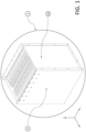
- FIG. 1 illustrates an embodiment of a battery module 1 comprising a group of battery cells placed in a vertical direction in a metal housing.
- FIG. 1 shows the battery module 1, a thin metal plate housing 5, and a thermal pad 6.
- the housing may be made from a thin metal plate, so therefore, we call it later as a thin metal plate housing 5.
- the battery module 1 may be formed in a shape of rectangular polyhedron, allowing easier scalability of the battery pack through assembling the battery modules 1 side by side without excessive gaps.
- the positive and negative terminals (i.e. electrodes) of the battery cells are visible on the top side of each of the battery cells (marked with + and - signs).
- the thin metal plate housing 5 is also capable to conduct thermal energy as it has a good thermal conductivity.
- the surface area along the outer surfaces of the battery module 1 is relatively large, and this enables an efficient thermal energy transfer from a heated hot spot to cooler areas.
- a thermal pad 6 may be placed along the XY-aligned surface of the battery module 1, in its two sides.
- ends of the thin metal plate housing 5 may be bent 90 degrees so that these bent edges are connectable to the end plates 10 of the battery module 1 by e.g. screws, welding or other fastening methods, i.e. by selected fastening means.
- the thin metal plate housing 5 surrounds the battery module 1 along all XY- and YZ-aligned end surfaces and the bottom surface as well. Now the thermal pad 6 will locate along the XY-aligned end surfaces so that it locates between the thin metal plate housing 5 and thermal fins 3 (not visible in FIG. 1 because they locate right under the thermal pad 6). In this embodiment, the thermal pad 6 will have good thermal conductivity, but it also will have a poor electric conductivity, in other words, it functions as an electric insulator. Thus, the safety increases with such an insulating layer, which still allows for proper thermal energy transfer between the battery cells' edges and the outer environment of the battery module.
- the thin metal plate housing 5 enables the proper cooling of the battery cells e.g. by air or liquid, depending on the requirements in various different applications.
- a relatively thin piece made of cellular rubber In between the adjacent cells, there can be a relatively thin piece made of cellular rubber, locating vertically between the vertically aligned cells and having substantially the same size (dimensions) in Y- and Z-directions as the battery cells 2 themselves.
- the purpose of the piece made of cellular rubber is to ensure a uniform compression pressure to the large side surface of the respective battery cells 2.
- each adjacent battery cell 2 there is a thermal fin 3, which extends and folds on top of a side edge of the battery cell 2 with 90 degrees angle, the bent parts of the thermal fins 3 forming a substantially planar vertical surface with large thermal conductivity for the battery modules 1.
- the same thermal fins 3 may also extend and be foldable along a bottom edge of the battery cell 2 with 90 degrees angle as well, where these bent parts of the thermal fins 3 will form a substantially horizontal surface on the bottom surface of the battery module.
- at least one side surface of each battery cell 2 will be in contact with a thermal fin 3.
- the XY-aligned side surfaces and the bottom surface will be covered (for most parts) with adjacent, bent sections of metal having a large thermal conductivity.
- thermal fins 3 along the bottom surface of the battery module, may have a contact with a foil heater 7 (not shown in FIG. 2 , but it is discussed later). Also a contact to a separate cooling element (system) can be enabled from some parts of the thermal fins 3. Therefore, an efficient heating and cooling possibility is obtained along the thermally conductive metal surfaces of the battery modules 1.
- the thermal energy distribution will be relatively uniform within the battery module 1, or at least such uniformity is enhanced with the presented thermal management system.
- the outside surface of the foil heater 7 may be insulated so that the radiated heat will propagate into the battery cells 2 and not to ambient environment outside the modules.
- the resulting system will still be optimized regarding the consumed space, and also symmetrical.
- the foil heater 7 may be located on an area, which is part of the other bent sections of the thermal fins 3. This means that the heating process will initiate somewhere on the XY-aligned side edges of the battery module 1.
- the foil heater 7 may be supplied by the battery pack or the respective battery module 1 itself, or by an external power source. Concerning the feeding wires of the foil heater 7, they may be located within the end plate 10 of the battery module 1, which leads into another advantage, where the wirings will not increase the outside dimensions of the battery module 1. Thus, the energy density is maximized also in this sense.
- FIG:s 3-7 illustrate some of the above elements (such as the foil heater 7) better and also from different angles and views, and especially FIG:s 6-7 also show a cooling system according to an embodiment, which can be installed within a battery pack.
- FIG. 3 illustrates a complete set of battery cells 2 within a single battery module 1 with related end plates 10, in an embodiment of the present invention.
- the thin metal plate housing 5 (discussed earlier in connection with FIG. 1 ) may be attached to the end plates 10 of the battery module 1 by e.g. screws.
- the end plates 10 may be made from aluminium.
- twenty-eight (28) battery cells are placed adjacently and each in a vertical alignment.
- the terminals i.e. the tabs may be ordered so that a pair of battery cells comprises the tabs as "plus and minus" or "minus and plus".
- This pair of reversely oriented battery cells 2 is "enclosed” with a thermal fin 3, which extends and folds on top of a side edge of these two battery cells 2 with 90 degrees angle. These bent sections can be seen as “vertical strips” along the longer side surface of the battery module 1.
- each battery cell 2 is in connection with at least one thermal fin 3, which has good thermal conductivity properties.
- the housing 5 will also conduct thermal energy well, and it also protects this end of the battery module physically if there is an impulse-typed force affecting the structure along the X-axis.
- FIG. 4 illustrates the bottom surface of the battery module 1 in more detail, in an embodiment.
- the shown elements are thermal fins 3, the thin metal plate housing 5, and the foil heater 7 (discussed already earlier).
- the battery cells 2 are now placed adjacently as in the final product, so therefore the bent parts of the thermal fins 3 form a large and practically uniform heat conducting surface, which reaches the side surface and the bottom surface of the battery module 1.
- the input wirings of the foil heater 7 can be seen to enter and go through the side parts of the end plates 10 in a vertical direction.
- these wirings are also protected physically, and because the structure is integrated in this sense, the length of the battery module 1 is not affected when the wirings are "added".
- the wirings for the foil heater 7 may extend to the next module along the end plate 10, so that the wirings form direct paths where applicable. Now a very compact structure with a proper heating functionality and thermally conducting side surfaces is obtained.
- FIG. 5 illustrates a yet another view of the finished battery module.
- the shown elements are thermal fins 3, the thin metal plate housing 5, and the foil heater 7, as in FIG. 4 .
- the battery module 1 structure is now shown as a finally assembled product.
- the foil heater 7 is aligned along the bottom surface of the battery module 1.
- the structure is a compact, rectangularly shaped element, which allows the assembling and stacking of modules in rows, columns and also layers (we mean X-, Y- and Z-directions), without any excessive gaps between the battery modules 1.
- FIG. 6 illustrates a group of battery modules 1 assembled together, where a cooling system with plate-like heat exchangers 8 is shown as well.
- the heating functionality is shown as well in the form of foil heaters 7 along the bottom surface of the battery modules 1.
- Thin metal plate housing 5 can be seen as well for each of the battery modules 1.
- the battery pack comprises heat exchangers 8, which can be plate-shaped, and which may locate on XY-planes of the battery modules 1, i.e. between adjacent battery modules in each XY-plane-aligned gap.
- the plate-shaped heat exchanger 8 may be formed like a curved pipe. If the cross-sectional area within the piping is looked at, it is preferably selected to be as large as possible in view of the module's XY-plane-aligned end wall. As FIG. 6 illustrates, the cross-sectional area of the piping can be selected to be over 50 % of the total XY-plane surface of a single battery module. The large cross-sectional area of the piping will make the thermal energy transfer (i.e.
- the heat exchanger 8 comprises a route for gas or liquid to flow through.
- the flowing substance can be also called as a coolant.
- the coolant can be directed to the piping or other kind of route of the heat exchanger 8 via pipes 9. They can also be called as coolant pipes 9.
- the pipes 9 may be suitable for circulating water through the heat exchanger 8. Some other coolant may be selected in some other embodiments.
- the main purpose of the heat exchangers 8 is that the excessive thermal energy created due to chemical reactions inside the battery modules 1 can be conducted off from the battery pack.
- the pipes 9 may direct water or other coolant to another element which cools water or the coolant once again.
- the same coolant material now having a cooler temperature can be directed once again to the incoming pipes 9 and to the heat exchangers 8.
- the heat exchanging system can be made as a closed circulation system, in an embodiment of the present invention.
- the gravimetric pressure from the above battery modules is meant to be directed onto flat top surfaces of current connectors (not shown). These current connectors are designed to reach to a slightly higher level than the top level of the pipes 9. Thus, the gravimetric force of the above locating battery module(s) will apply to the current connectors, also ensuring better connections in electric sense as well.
- the foil heater 7 locates along the bottom surface of the battery module 1 in the finalized product.
- the wirings for the foil heaters 7 may locate along the YZ-planes like shown. This is merely one possible way of placing the wirings along this surface. Still, the wirings are integrated within the housing, which makes them also as physically protected.
- FIG. 7 illustrates another view of a single battery module with heating and cooling functionalities.
- This is an exploded view during the assembly process of the battery pack.
- the same elements, as in FIG. 6 are shown; in other words, thin metal plate housing 5, foil heater 7, heat exchangers 8, and (coolant) pipes 9.
- This exploded view shows that the heat exchangers 8 may be placed between each adjacent battery module 1 in the Z-direction.
- the exploded view also shows a half-completed situation concerning the instalment of the foil heater 7, as in this view the foil heater 7 is about to be lowered to the bottom surface of the battery module 1. Then the battery cells 2 can be inserted (not shown here), and the rest of the parts as well.
- the final row of battery modules 1 will look like e.g. in FIG.
- the battery pack to be built will enable one basic functionality relating to efficient thermal energy handling:
- the heating process will originate from the bottom surface of the battery modules 1, and the cooling process will originate from the XY-surfaces between each adjacent battery module 1.
- the battery pack (together with its control logic described elsewhere) is able to handle any created hot spots within the battery structure.
- the battery pack is also able to handle cold temperatures originating from the ambient environment, where the battery pack is actually used and implemented.
- the heating application is of utmost importance for the battery packs used in these kinds of vehicles.
- these thermal management possibilities allow us to use the battery packs in a variety of different weather conditions. This allows proper outdoor usage for electric devices and electric vehicles.
- the service life of the battery pack will be longer and the reliability of the battery pack will clearly enhance in various conditions, when the thermal energy management system according to the present invention is implemented.
- the present invention also comprises an aspect of applying software, i.e. a computer program and respective computer program product for controlling the thermal management of the battery pack.
- software i.e. a computer program and respective computer program product for controlling the thermal management of the battery pack.
- the above disclosed method steps relating to the thermal energy handling of the battery pack and the battery modules as well, can be performed through executing them via a computer program, i.e. program code involving these method steps.
- the computer program may be executed by a processor or controller or microcontroller, and the piece of software may be stored in a local memory, or in an external location, such as in a cloud service.
- the computer/processor executing the steps may be a microcontroller integrated in the battery pack itself as a small functional entity.
- the system may comprise also at least one temperature sensor for detecting e.g. in various locations around the battery pack, how the thermal situation behaves. If there is a hotspot arising in certain part of the battery pack, the cooling functionality can be activated by the (
- a controller and at least one temperature sensor configured to sense the temperature within the battery pack, and to control the temperature of the battery pack by activating and deactivating the foil heaters 7 as desired.
- the controller is configured to control also the activity of the cooling system for controlling the temperature of the battery pack in case of excessive heat emerges within the battery pack, in an embodiment of the present invention.
- the thin metal plate housing 5 is one of the elements here, which enables high energy density of the battery modules 1.
- the housing 5 is formed by thin and planar elements made e.g. from aluminium, it gives a possibility to place battery modules 1 adjacently without any remaining gaps.
- the length along the X-dimension for the thin metal plate housing 5 of a single battery module 1 can be freely scaled based on the desired number of battery cells 2 to be placed within a single module. Thus, the modules' lengths in the X-direction may be selected.
- a battery pack may be built by placing battery modules 1 side by side in different directions.
- a complete battery pack comprising several battery modules 1 may be created, which has an advantage that the volumetric energy density of the whole battery pack can thus be maximized.
- the present invention is suitable for battery pack solutions comprising pouch cell - typed battery cells.
- the presented heating and cooling options are most advantageous in market areas, where environmental temperatures may vary in a large range, and where the battery pack is prone to excessive internal heating in at least some use situation.
- the presented thermal management system according to the present invention is cost-efficient, thermally efficient (concerning the speed of the thermal energy transfer), and it enables an energy reserve with a large energy density. This is advantageous in application areas, which have restricted or even "oddly shaped" places available for the batteries. Also the application areas, where there are mass restrictions of the batteries, are applicable with the present invention.
- thermal energy management is an important issue due to excessive heat due to battery itself combined with possibly climate related reasons; or on the other hand, excessively cold operating circumstances; these are handled well with the thermal management system of the present invention.
- suitable application areas are on-road and off-road electric vehicles, such as electric cars and electric sleds.
- any other application, where the supplied energy is provided via batteries, is suitable to be provided with the principle of the present invention.
- One practical example is formed by stationary energy storage systems or rechargeable energy storage systems.
Landscapes
- Engineering & Computer Science (AREA)
- Chemical & Material Sciences (AREA)
- Chemical Kinetics & Catalysis (AREA)
- Electrochemistry (AREA)
- General Chemical & Material Sciences (AREA)
- Manufacturing & Machinery (AREA)
- Mechanical Engineering (AREA)
- Transportation (AREA)
- Life Sciences & Earth Sciences (AREA)
- Sustainable Development (AREA)
- Sustainable Energy (AREA)
- Power Engineering (AREA)
- Automation & Control Theory (AREA)
- Combustion & Propulsion (AREA)
- Inorganic Chemistry (AREA)
- Secondary Cells (AREA)
- Battery Mounting, Suspending (AREA)
Claims (13)
- Thermisch steuerbares Batteriepack, wobei das thermisch steuerbare Batteriepack Folgendes umfasst:- mindestens ein Batteriemodul (1), das jeweils eine Vielzahl von Batteriezellen (2) umfasst,- jedes Batteriemodul (1) ist an mindestens drei Seiten des Batteriemoduls (1) von einem Metallblechgehäuse (5) umgeben,- eine thermische Rippe (3) zwischen einigen der benachbarten Batteriezellen (2), sodass jede Batteriezelle (2) Kontakt zu mindestens einer thermischen Rippe (3) hat, wobei sich die thermischen Rippen (3) erstrecken und auf der Oberseite einer Seitenkante der Batteriezelle (2) mit einem Winkel von 90 Grad gebogen sind, sodass gebogene Teile der thermischen Rippen (3) eine im Wesentlichen planare vertikale äußere Oberfläche mit einer großen thermischen Leitfähigkeit für die Batteriemodule (1) bilden, wobei die thermischen Rippen (3) aus Metallblech hergestellt sind, dadurch gekennzeichnet, dass das Batteriepack ferner Folgendes umfasst- thermische Rippen (3), die sich entlang einer Unterkante der Batteriezelle (2) mit einem Winkel von 90 Grad erstrecken und faltbar sind, wobei die gebogenen Teile der thermischen Rippen (3) eine im Wesentlichen horizontale Oberfläche auf der unteren Oberfläche des Batteriemoduls (1) bilden,- ein Folienheizelement (7) entlang der unteren Oberfläche des Batteriemoduls (1), das durch das Batteriepack selbst oder durch eine äußere Leistungsquelle versorgt wird,- ein thermisches Pad zwischen dem Metallblechgehäuse (5) und den gebogenen Teilen der thermischen Rippen (3) an vertikalen Endoberflächen des Batteriemoduls (1), wobei das thermische Pad aus einem elektrisch isolierenden Material hergestellt ist und thermisch leitfähig ist,- eine Steuerung und mindestens einen Temperatursensor, der konfiguriert ist, die Temperatur innerhalb des Batteriepacks zu erfassen und die Temperatur des Batteriepacks durch Aktivieren und Deaktivieren der Folienheizelemente (7) nach Wunsch zu steuern,- die zwei vertikalen Oberflächen der Batteriemodule (1), umfassend die thermischen Pads, mit Wärmeaustauschern (8) versehen sind,- die obere Oberfläche der Batteriemodule (1) mit Kühlmittelrohren (9) versehen ist, die den Wärmeaustauschern (8) Luft oder Flüssigkeit mit der gewünschten Temperatur zuführen, und- die Steuerung ist konfiguriert, auch die Aktivität des Kühlsystems zum Steuern der Temperatur des Batteriepacks im Falle einer übermäßigen Erwärmung des Batteriepacks zu kontrollieren.
- Thermisch steuerbares Batteriepack nach Anspruch 1, dadurch gekennzeichnet, dass das Batteriepack ein Kühlsystem umfasst, sodass sich Wärmeaustauscher (8) in jeder Lücke der benachbarten Batteriemodule (1) befinden, und dass der Wärmeaustauscher (8) einen gekrümmten Weg für Flüssigkeit oder Gas umfasst, um mindestens die Hälfte der vertikalen seitlichen Oberfläche der Batteriemodule (1) für eine effiziente Kühlung abzudecken.
- Thermisch steuerbares Batteriepack nach Anspruch 1, dadurch gekennzeichnet, dass die thermischen Rippen (3) über das Folienheizelement (7) erwärmt werden können, das durch Verdrahtungen versorgt wird, die über das Blechgehäuse (5) des Batteriemoduls (1) integriert geführt werden.
- Thermisch steuerbares Batteriepack nach Anspruch 3, dadurch gekennzeichnet, dass die Eingangsverdrahtungen des Folienheizelements (7) durch die Seitenteile von Endplatten (10) des Metallblechgehäuses (5) in vertikaler Richtung ein- und ausgehen.
- Thermisch steuerbares Batteriepack nach Anspruch 1, dadurch gekennzeichnet, dass an einer oberen Oberfläche der Batteriemodule (1) Anschlusslaschen der Batteriezellen (2) als nach oben gerichtete Vorsprünge angeordnet sind, die eine serielle Verbindung der Batteriezellen (2) in gewünschter Weise ermöglichen.
- Thermisch steuerbares Batteriepack nach Anspruch 1, dadurch gekennzeichnet, dass die Batteriemodule (1) relativ dünne Stücke aus Zellkautschuk umfassen, die vertikal zwischen den vertikal ausgerichteten Batteriezellen (2) angeordnet sind und im Wesentlichen die gleiche Größe in Y- und Z-Richtungen mit den Batteriezellen (2) aufweisen, um einen gleichmäßigen Kompressionsdruck auf die großen seitlichen Oberflächen der jeweiligen Batteriezellen (2) sicherzustellen.
- Thermisch steuerbares Batteriepack nach Anspruch 1, dadurch gekennzeichnet, dass die Batteriemodule (1) in Form eines rechteckigen Polyeders gebildet sind, was eine Skalierbarkeit des Batteriepacks durch Zusammensetzen der Batteriemodule (1) nebeneinander ohne übermäßige Lücken ermöglicht.
- Thermisch steuerbares Batteriepack nach Anspruch 1, dadurch gekennzeichnet, dass Enden des Metallblechgehäuses (5) um 90 Grad gebogen sind, sodass diese gebogenen Kanten durch ausgewählte Befestigungsmittel mit Endplatten (10) des Batteriemoduls (1) verbindbar sind.
- Thermisch steuerbares Batteriepack nach Anspruch 1, dadurch gekennzeichnet, dass die äußere Oberfläche des Folienheizelements (7) isoliert ist, sodass sich die ausgestrahlte Wärme in die Batteriezellen (2) und nicht in die Umgebung außerhalb der Batteriemodule (1) ausbreitet.
- Thermisch steuerbares Batteriepack nach Anspruch 1, dadurch gekennzeichnet, dass die Folienheizelemente (7) an einem Bereich angeordnet sind, der Teil der anderen gebogenen, vertikalen Abschnitte der thermischen Rippen (3) ist.
- Thermisch steuerbares Batteriepack nach Anspruch 1, dadurch gekennzeichnet, dass das Wärmeaustauschsystem als geschlossenes Zirkulationssystem hergestellt ist.
- Thermisch steuerbares Batteriepack nach Anspruch 1, dadurch gekennzeichnet, dass alle Lücken zwischen den benachbarten Batteriemodulen (1) entlang der Z-Achsenrichtung mit Wärmeaustauschern (8) versehen sind, zusammen mit den Endoberflächen der Batteriemodule (1), die gleichzeitig auch äußere Oberflächen des gesamten Batteriepacks sind.
- Verwendung des thermisch steuerbaren Batteriepacks nach einem der Ansprüche 1 bis 12, dadurch gekennzeichnet, dass das Batteriepack in On-Road- oder Off-Road-Elektrofahrzeugen, umfassend Elektroautos und Elektroschlitten, oder in jeder anderen Anwendung, wo die zugeführte Energie über Batterien bereitgestellt wird, oder in stationären Energiespeichersystemen oder wiederaufladbaren Energiespeichersystemen angewendet wird.
Applications Claiming Priority (2)
| Application Number | Priority Date | Filing Date | Title |
|---|---|---|---|
| FI20215114A FI131826B1 (en) | 2021-02-03 | 2021-02-03 | Thermal management of a battery module and of a battery pack |
| PCT/FI2022/050065 WO2022167726A2 (en) | 2021-02-03 | 2022-02-02 | Thermal management of a battery module and of a battery pack |
Publications (2)
| Publication Number | Publication Date |
|---|---|
| EP4289017A2 EP4289017A2 (de) | 2023-12-13 |
| EP4289017B1 true EP4289017B1 (de) | 2025-03-26 |
Family
ID=80623536
Family Applications (1)
| Application Number | Title | Priority Date | Filing Date |
|---|---|---|---|
| EP22707205.5A Active EP4289017B1 (de) | 2021-02-03 | 2022-02-02 | Wärmemanagement eines batteriemoduls und eines batteriepacks |
Country Status (5)
| Country | Link |
|---|---|
| US (1) | US20240304887A1 (de) |
| EP (1) | EP4289017B1 (de) |
| CA (1) | CA3207365A1 (de) |
| FI (2) | FI131826B1 (de) |
| WO (1) | WO2022167726A2 (de) |
Families Citing this family (1)
| Publication number | Priority date | Publication date | Assignee | Title |
|---|---|---|---|---|
| CN116093495A (zh) * | 2022-12-27 | 2023-05-09 | 惠州市赛能电池有限公司 | 电芯用电热件、电芯模组及其控制方法、以及无人机 |
Family Cites Families (16)
| Publication number | Priority date | Publication date | Assignee | Title |
|---|---|---|---|---|
| US5948298A (en) | 1996-04-26 | 1999-09-07 | Ford Global Technologies, Inc. | Battery heating system |
| US7531270B2 (en) * | 2006-10-13 | 2009-05-12 | Enerdel, Inc. | Battery pack with integral cooling and bussing devices |
| DE102009018787A1 (de) * | 2009-04-24 | 2010-10-28 | Akasol Engineering Gmbh | Batteriemodul |
| JP5659554B2 (ja) * | 2010-05-17 | 2015-01-28 | 株式会社デンソー | 電池パック |
| US9431688B2 (en) | 2010-05-21 | 2016-08-30 | GM Global Technology Operations LLC | Method for heating a high voltage vehicle battery |
| JP5625115B2 (ja) * | 2010-08-16 | 2014-11-12 | エルジー・ケム・リミテッド | 優れた熱放射特性を有する小型構造のバッテリーモジュール、及びそのバッテリーモジュールを使用する中型又は大型のバッテリーパック |
| JP5978214B2 (ja) | 2010-09-02 | 2016-08-24 | アカソル・ゲゼルシャフト・ミット・ベシュレンクテル・ハフツング | 冷却モジュールおよび冷却モジュールの製造方法 |
| CN102280672B (zh) * | 2011-07-01 | 2014-07-23 | 中国电力科学研究院 | 一种车用动力电池箱的热管控温系统 |
| CN204424410U (zh) | 2015-03-05 | 2015-06-24 | 中航锂电(洛阳)有限公司 | 电加热装置及使用该电加热装置的电池模块 |
| KR101865995B1 (ko) | 2015-03-27 | 2018-06-08 | 주식회사 엘지화학 | 배터리 모듈 |
| KR101780037B1 (ko) | 2015-04-22 | 2017-09-19 | 주식회사 엘지화학 | 배터리 셀 냉각장치 및 이를 포함하는 배터리 모듈 |
| CN204947033U (zh) | 2015-07-21 | 2016-01-06 | 宁德时代新能源科技有限公司 | 锂二次电池模组 |
| CN205159470U (zh) | 2015-11-03 | 2016-04-13 | 宁德时代新能源科技股份有限公司 | 一种电池模组 |
| CN106816671B (zh) * | 2015-12-01 | 2019-02-22 | 宁德时代新能源科技股份有限公司 | 电池单元、电池模组及电池包 |
| CN206388796U (zh) * | 2017-01-18 | 2017-08-08 | 华霆(合肥)动力技术有限公司 | 电源装置及供电系统 |
| CN208655742U (zh) | 2018-08-20 | 2019-03-26 | 合肥国轩高科动力能源有限公司 | 一种动力电池模组 |
-
2021
- 2021-02-03 FI FI20215114A patent/FI131826B1/en active
-
2022
- 2022-02-02 FI FIEP22707205.5T patent/FI4289017T3/fi active
- 2022-02-02 CA CA3207365A patent/CA3207365A1/en active Pending
- 2022-02-02 WO PCT/FI2022/050065 patent/WO2022167726A2/en not_active Ceased
- 2022-02-02 EP EP22707205.5A patent/EP4289017B1/de active Active
- 2022-02-02 US US18/264,037 patent/US20240304887A1/en active Pending
Also Published As
| Publication number | Publication date |
|---|---|
| CA3207365A1 (en) | 2022-08-11 |
| EP4289017A2 (de) | 2023-12-13 |
| WO2022167726A2 (en) | 2022-08-11 |
| FI4289017T3 (fi) | 2025-06-30 |
| US20240304887A1 (en) | 2024-09-12 |
| WO2022167726A3 (en) | 2022-11-24 |
| FI131826B1 (en) | 2025-12-19 |
| FI20215114A1 (en) | 2022-08-04 |
Similar Documents
| Publication | Publication Date | Title |
|---|---|---|
| EP2763214B1 (de) | Batteriemodul | |
| KR102762539B1 (ko) | 버스바 프레임 조립체 및 이를 포함하는 배터리 모듈 | |
| EP2416438B1 (de) | Batteriemodul mit erhöhter sicherheit | |
| JP6626577B2 (ja) | バッテリーモジュール及びこれを含むバッテリーパック、自動車 | |
| JP6636638B2 (ja) | バッテリーモジュール及びこれを含むバッテリーパック、自動車 | |
| JP2020523748A (ja) | バッテリーパック | |
| CN214254530U (zh) | 电池及包括该电池的装置 | |
| KR101445214B1 (ko) | 전력 배터리 팩 냉각 장치 | |
| EP3293794B1 (de) | Stromschienenkühlungsverfahren und -systeme | |
| KR20120075431A (ko) | 배터리 모듈 수납장치, 배터리 모듈 온도조절 장치 및 이들을 포함하는 전력 저장 시스템 | |
| CN115152081B (zh) | 电池组及包括其的电池组装置 | |
| KR20120016590A (ko) | 콤팩트한 구조와 우수한 방열 특성의 전지모듈 및 그것을 포함하는 중대형 전지팩 | |
| KR20180013460A (ko) | 배터리 장치 | |
| CN115917837A (zh) | 电池模块及包括该电池模块的电池组 | |
| KR101232784B1 (ko) | 이차전지 냉각장치 및 이차전지 운전열을 이용한 난방 시스템 | |
| JP5904109B2 (ja) | 蓄電モジュール及び蓄電モジュールの温度調節構造 | |
| CN110739425A (zh) | 一种高防护等级的立式锂电池包空冷式热管理系统及方法 | |
| EP4289017B1 (de) | Wärmemanagement eines batteriemoduls und eines batteriepacks | |
| KR102683482B1 (ko) | 전지 팩 | |
| CN220510114U (zh) | 电池箱、电池和用电装置 | |
| JP2025028970A (ja) | 電池、電力消費装置、電池の製造方法及び装置 | |
| CN221304788U (zh) | 二次电池 | |
| CN119275407A (zh) | 冷板 | |
| CN220604768U (zh) | 一种自带冷却结构的电芯及包含该电芯的电池模组 | |
| CN113871746A (zh) | 电池以及电池模组 |
Legal Events
| Date | Code | Title | Description |
|---|---|---|---|
| STAA | Information on the status of an ep patent application or granted ep patent |
Free format text: STATUS: UNKNOWN |
|
| STAA | Information on the status of an ep patent application or granted ep patent |
Free format text: STATUS: THE INTERNATIONAL PUBLICATION HAS BEEN MADE |
|
| PUAI | Public reference made under article 153(3) epc to a published international application that has entered the european phase |
Free format text: ORIGINAL CODE: 0009012 |
|
| STAA | Information on the status of an ep patent application or granted ep patent |
Free format text: STATUS: REQUEST FOR EXAMINATION WAS MADE |
|
| 17P | Request for examination filed |
Effective date: 20230823 |
|
| AK | Designated contracting states |
Kind code of ref document: A2 Designated state(s): AL AT BE BG CH CY CZ DE DK EE ES FI FR GB GR HR HU IE IS IT LI LT LU LV MC MK MT NL NO PL PT RO RS SE SI SK SM TR |
|
| DAV | Request for validation of the european patent (deleted) | ||
| DAX | Request for extension of the european patent (deleted) | ||
| GRAP | Despatch of communication of intention to grant a patent |
Free format text: ORIGINAL CODE: EPIDOSNIGR1 |
|
| STAA | Information on the status of an ep patent application or granted ep patent |
Free format text: STATUS: GRANT OF PATENT IS INTENDED |
|
| INTG | Intention to grant announced |
Effective date: 20240912 |
|
| GRAS | Grant fee paid |
Free format text: ORIGINAL CODE: EPIDOSNIGR3 |
|
| GRAA | (expected) grant |
Free format text: ORIGINAL CODE: 0009210 |
|
| STAA | Information on the status of an ep patent application or granted ep patent |
Free format text: STATUS: THE PATENT HAS BEEN GRANTED |
|
| AK | Designated contracting states |
Kind code of ref document: B1 Designated state(s): AL AT BE BG CH CY CZ DE DK EE ES FI FR GB GR HR HU IE IS IT LI LT LU LV MC MK MT NL NO PL PT RO RS SE SI SK SM TR |
|
| REG | Reference to a national code |
Ref country code: GB Ref legal event code: FG4D |
|
| REG | Reference to a national code |
Ref country code: CH Ref legal event code: EP |
|
| REG | Reference to a national code |
Ref country code: DE Ref legal event code: R096 Ref document number: 602022012254 Country of ref document: DE |
|
| REG | Reference to a national code |
Ref country code: IE Ref legal event code: FG4D |
|
| REG | Reference to a national code |
Ref country code: FI Ref legal event code: FGE |
|
| PG25 | Lapsed in a contracting state [announced via postgrant information from national office to epo] |
Ref country code: RS Free format text: LAPSE BECAUSE OF FAILURE TO SUBMIT A TRANSLATION OF THE DESCRIPTION OR TO PAY THE FEE WITHIN THE PRESCRIBED TIME-LIMIT Effective date: 20250626 |
|
| REG | Reference to a national code |
Ref country code: LT Ref legal event code: MG9D |
|
| REG | Reference to a national code |
Ref country code: SE Ref legal event code: TRGR |
|
| PG25 | Lapsed in a contracting state [announced via postgrant information from national office to epo] |
Ref country code: HR Free format text: LAPSE BECAUSE OF FAILURE TO SUBMIT A TRANSLATION OF THE DESCRIPTION OR TO PAY THE FEE WITHIN THE PRESCRIBED TIME-LIMIT Effective date: 20250326 |
|
| PG25 | Lapsed in a contracting state [announced via postgrant information from national office to epo] |
Ref country code: LV Free format text: LAPSE BECAUSE OF FAILURE TO SUBMIT A TRANSLATION OF THE DESCRIPTION OR TO PAY THE FEE WITHIN THE PRESCRIBED TIME-LIMIT Effective date: 20250326 |
|
| PG25 | Lapsed in a contracting state [announced via postgrant information from national office to epo] |
Ref country code: BG Free format text: LAPSE BECAUSE OF FAILURE TO SUBMIT A TRANSLATION OF THE DESCRIPTION OR TO PAY THE FEE WITHIN THE PRESCRIBED TIME-LIMIT Effective date: 20250326 Ref country code: GR Free format text: LAPSE BECAUSE OF FAILURE TO SUBMIT A TRANSLATION OF THE DESCRIPTION OR TO PAY THE FEE WITHIN THE PRESCRIBED TIME-LIMIT Effective date: 20250627 |
|
| REG | Reference to a national code |
Ref country code: NL Ref legal event code: MP Effective date: 20250326 |
|
| PG25 | Lapsed in a contracting state [announced via postgrant information from national office to epo] |
Ref country code: NL Free format text: LAPSE BECAUSE OF FAILURE TO SUBMIT A TRANSLATION OF THE DESCRIPTION OR TO PAY THE FEE WITHIN THE PRESCRIBED TIME-LIMIT Effective date: 20250326 |
|
| PG25 | Lapsed in a contracting state [announced via postgrant information from national office to epo] |
Ref country code: SM Free format text: LAPSE BECAUSE OF FAILURE TO SUBMIT A TRANSLATION OF THE DESCRIPTION OR TO PAY THE FEE WITHIN THE PRESCRIBED TIME-LIMIT Effective date: 20250326 |
|
| PG25 | Lapsed in a contracting state [announced via postgrant information from national office to epo] |
Ref country code: ES Free format text: LAPSE BECAUSE OF FAILURE TO SUBMIT A TRANSLATION OF THE DESCRIPTION OR TO PAY THE FEE WITHIN THE PRESCRIBED TIME-LIMIT Effective date: 20250326 Ref country code: PT Free format text: LAPSE BECAUSE OF FAILURE TO SUBMIT A TRANSLATION OF THE DESCRIPTION OR TO PAY THE FEE WITHIN THE PRESCRIBED TIME-LIMIT Effective date: 20250728 |
|
| PG25 | Lapsed in a contracting state [announced via postgrant information from national office to epo] |
Ref country code: PL Free format text: LAPSE BECAUSE OF FAILURE TO SUBMIT A TRANSLATION OF THE DESCRIPTION OR TO PAY THE FEE WITHIN THE PRESCRIBED TIME-LIMIT Effective date: 20250326 |
|
| PG25 | Lapsed in a contracting state [announced via postgrant information from national office to epo] |
Ref country code: EE Free format text: LAPSE BECAUSE OF FAILURE TO SUBMIT A TRANSLATION OF THE DESCRIPTION OR TO PAY THE FEE WITHIN THE PRESCRIBED TIME-LIMIT Effective date: 20250326 |
|
| PG25 | Lapsed in a contracting state [announced via postgrant information from national office to epo] |
Ref country code: RO Free format text: LAPSE BECAUSE OF FAILURE TO SUBMIT A TRANSLATION OF THE DESCRIPTION OR TO PAY THE FEE WITHIN THE PRESCRIBED TIME-LIMIT Effective date: 20250326 |
|
| PG25 | Lapsed in a contracting state [announced via postgrant information from national office to epo] |
Ref country code: SK Free format text: LAPSE BECAUSE OF FAILURE TO SUBMIT A TRANSLATION OF THE DESCRIPTION OR TO PAY THE FEE WITHIN THE PRESCRIBED TIME-LIMIT Effective date: 20250326 |
|
| PG25 | Lapsed in a contracting state [announced via postgrant information from national office to epo] |
Ref country code: IS Free format text: LAPSE BECAUSE OF FAILURE TO SUBMIT A TRANSLATION OF THE DESCRIPTION OR TO PAY THE FEE WITHIN THE PRESCRIBED TIME-LIMIT Effective date: 20250726 |
|
| REG | Reference to a national code |
Ref country code: DE Ref legal event code: R097 Ref document number: 602022012254 Country of ref document: DE |
|
| PG25 | Lapsed in a contracting state [announced via postgrant information from national office to epo] |
Ref country code: DK Free format text: LAPSE BECAUSE OF FAILURE TO SUBMIT A TRANSLATION OF THE DESCRIPTION OR TO PAY THE FEE WITHIN THE PRESCRIBED TIME-LIMIT Effective date: 20250326 |
|
| PG25 | Lapsed in a contracting state [announced via postgrant information from national office to epo] |
Ref country code: CZ Free format text: LAPSE BECAUSE OF FAILURE TO SUBMIT A TRANSLATION OF THE DESCRIPTION OR TO PAY THE FEE WITHIN THE PRESCRIBED TIME-LIMIT Effective date: 20250326 |
|
| PLBE | No opposition filed within time limit |
Free format text: ORIGINAL CODE: 0009261 |
|
| STAA | Information on the status of an ep patent application or granted ep patent |
Free format text: STATUS: NO OPPOSITION FILED WITHIN TIME LIMIT |
|
| REG | Reference to a national code |
Ref country code: CH Ref legal event code: L10 Free format text: ST27 STATUS EVENT CODE: U-0-0-L10-L00 (AS PROVIDED BY THE NATIONAL OFFICE) Effective date: 20260211 |
|
| REG | Reference to a national code |
Ref country code: CH Ref legal event code: U11 Free format text: ST27 STATUS EVENT CODE: U-0-0-U10-U11 (AS PROVIDED BY THE NATIONAL OFFICE) Effective date: 20260301 |
|
| 26N | No opposition filed |
Effective date: 20260105 |
|
| PGFP | Annual fee paid to national office [announced via postgrant information from national office to epo] |
Ref country code: SE Payment date: 20260227 Year of fee payment: 5 |
|
| PGFP | Annual fee paid to national office [announced via postgrant information from national office to epo] |
Ref country code: GB Payment date: 20260224 Year of fee payment: 5 |
|
| PGFP | Annual fee paid to national office [announced via postgrant information from national office to epo] |
Ref country code: NO Payment date: 20260302 Year of fee payment: 5 Ref country code: DE Payment date: 20260225 Year of fee payment: 5 |
|
| PGFP | Annual fee paid to national office [announced via postgrant information from national office to epo] |
Ref country code: AT Payment date: 20260301 Year of fee payment: 5 |
|
| PGFP | Annual fee paid to national office [announced via postgrant information from national office to epo] |
Ref country code: IT Payment date: 20260227 Year of fee payment: 5 |
|
| PGFP | Annual fee paid to national office [announced via postgrant information from national office to epo] |
Ref country code: FR Payment date: 20260224 Year of fee payment: 5 |
|
| PGFP | Annual fee paid to national office [announced via postgrant information from national office to epo] |
Ref country code: CH Payment date: 20260301 Year of fee payment: 5 |