EP4288727B1 - Cryosauna - Google Patents
Cryosauna Download PDFInfo
- Publication number
- EP4288727B1 EP4288727B1 EP21789603.4A EP21789603A EP4288727B1 EP 4288727 B1 EP4288727 B1 EP 4288727B1 EP 21789603 A EP21789603 A EP 21789603A EP 4288727 B1 EP4288727 B1 EP 4288727B1
- Authority
- EP
- European Patent Office
- Prior art keywords
- cryosauana
- baffle plate
- evaporator
- temperature homogeneity
- heat exchanger
- Prior art date
- Legal status (The legal status is an assumption and is not a legal conclusion. Google has not performed a legal analysis and makes no representation as to the accuracy of the status listed.)
- Active
Links
Images

Classifications
-
- A—HUMAN NECESSITIES
- A61—MEDICAL OR VETERINARY SCIENCE; HYGIENE
- A61F—FILTERS IMPLANTABLE INTO BLOOD VESSELS; PROSTHESES; DEVICES PROVIDING PATENCY TO, OR PREVENTING COLLAPSING OF, TUBULAR STRUCTURES OF THE BODY, e.g. STENTS; ORTHOPAEDIC, NURSING OR CONTRACEPTIVE DEVICES; FOMENTATION; TREATMENT OR PROTECTION OF EYES OR EARS; BANDAGES, DRESSINGS OR ABSORBENT PADS; FIRST-AID KITS
- A61F7/00—Heating or cooling appliances for medical or therapeutic treatment of the human body
- A61F7/0053—Cabins, rooms, chairs or units for treatment with a hot or cold circulating fluid
-
- F—MECHANICAL ENGINEERING; LIGHTING; HEATING; WEAPONS; BLASTING
- F25—REFRIGERATION OR COOLING; COMBINED HEATING AND REFRIGERATION SYSTEMS; HEAT PUMP SYSTEMS; MANUFACTURE OR STORAGE OF ICE; LIQUEFACTION SOLIDIFICATION OF GASES
- F25D—REFRIGERATORS; COLD ROOMS; ICE-BOXES; COOLING OR FREEZING APPARATUS NOT OTHERWISE PROVIDED FOR
- F25D17/00—Arrangements for circulating cooling fluids; Arrangements for circulating gas, e.g. air, within refrigerated spaces
- F25D17/04—Arrangements for circulating cooling fluids; Arrangements for circulating gas, e.g. air, within refrigerated spaces for circulating air, e.g. by convection
-
- A—HUMAN NECESSITIES
- A61—MEDICAL OR VETERINARY SCIENCE; HYGIENE
- A61H—PHYSICAL THERAPY APPARATUS, e.g. DEVICES FOR LOCATING OR STIMULATING REFLEX POINTS IN THE BODY; ARTIFICIAL RESPIRATION; MASSAGE; BATHING DEVICES FOR SPECIAL THERAPEUTIC OR HYGIENIC PURPOSES OR SPECIFIC PARTS OF THE BODY
- A61H33/00—Bathing devices for special therapeutic or hygienic purposes
- A61H33/06—Artificial hot-air or cold-air baths; Steam or gas baths or douches, e.g. sauna or Finnish baths
-
- F—MECHANICAL ENGINEERING; LIGHTING; HEATING; WEAPONS; BLASTING
- F25—REFRIGERATION OR COOLING; COMBINED HEATING AND REFRIGERATION SYSTEMS; HEAT PUMP SYSTEMS; MANUFACTURE OR STORAGE OF ICE; LIQUEFACTION SOLIDIFICATION OF GASES
- F25D—REFRIGERATORS; COLD ROOMS; ICE-BOXES; COOLING OR FREEZING APPARATUS NOT OTHERWISE PROVIDED FOR
- F25D11/00—Self-contained movable devices, e.g. domestic refrigerators
-
- F—MECHANICAL ENGINEERING; LIGHTING; HEATING; WEAPONS; BLASTING
- F25—REFRIGERATION OR COOLING; COMBINED HEATING AND REFRIGERATION SYSTEMS; HEAT PUMP SYSTEMS; MANUFACTURE OR STORAGE OF ICE; LIQUEFACTION SOLIDIFICATION OF GASES
- F25D—REFRIGERATORS; COLD ROOMS; ICE-BOXES; COOLING OR FREEZING APPARATUS NOT OTHERWISE PROVIDED FOR
- F25D16/00—Devices using a combination of a cooling mode associated with refrigerating machinery with a cooling mode not associated with refrigerating machinery
-
- A—HUMAN NECESSITIES
- A61—MEDICAL OR VETERINARY SCIENCE; HYGIENE
- A61H—PHYSICAL THERAPY APPARATUS, e.g. DEVICES FOR LOCATING OR STIMULATING REFLEX POINTS IN THE BODY; ARTIFICIAL RESPIRATION; MASSAGE; BATHING DEVICES FOR SPECIAL THERAPEUTIC OR HYGIENIC PURPOSES OR SPECIFIC PARTS OF THE BODY
- A61H33/00—Bathing devices for special therapeutic or hygienic purposes
- A61H33/06—Artificial hot-air or cold-air baths; Steam or gas baths or douches, e.g. sauna or Finnish baths
- A61H2033/061—Artificial hot-air baths
-
- F—MECHANICAL ENGINEERING; LIGHTING; HEATING; WEAPONS; BLASTING
- F25—REFRIGERATION OR COOLING; COMBINED HEATING AND REFRIGERATION SYSTEMS; HEAT PUMP SYSTEMS; MANUFACTURE OR STORAGE OF ICE; LIQUEFACTION SOLIDIFICATION OF GASES
- F25D—REFRIGERATORS; COLD ROOMS; ICE-BOXES; COOLING OR FREEZING APPARATUS NOT OTHERWISE PROVIDED FOR
- F25D2317/00—Details or arrangements for circulating cooling fluids; Details or arrangements for circulating gas, e.g. air, within refrigerated spaces, not provided for in other groups of this subclass
- F25D2317/06—Details or arrangements for circulating cooling fluids; Details or arrangements for circulating gas, e.g. air, within refrigerated spaces, not provided for in other groups of this subclass with forced air circulation
- F25D2317/063—Details or arrangements for circulating cooling fluids; Details or arrangements for circulating gas, e.g. air, within refrigerated spaces, not provided for in other groups of this subclass with forced air circulation with air guides
-
- F—MECHANICAL ENGINEERING; LIGHTING; HEATING; WEAPONS; BLASTING
- F28—HEAT EXCHANGE IN GENERAL
- F28F—DETAILS OF HEAT-EXCHANGE AND HEAT-TRANSFER APPARATUS, OF GENERAL APPLICATION
- F28F1/00—Tubular elements; Assemblies of tubular elements
- F28F1/10—Tubular elements and assemblies thereof with means for increasing heat-transfer area, e.g. with fins, with projections, with recesses
- F28F1/12—Tubular elements and assemblies thereof with means for increasing heat-transfer area, e.g. with fins, with projections, with recesses the means being only outside the tubular element
- F28F1/126—Tubular elements and assemblies thereof with means for increasing heat-transfer area, e.g. with fins, with projections, with recesses the means being only outside the tubular element consisting of zig-zag shaped fins
Definitions
- the invention relates to a cryosauna according to the preamble of claim 1.
- the invention relates to a method for producing temperature homogeneity in a cryosauna.
- Cold chambers are known from the state of the art and are often also referred to as low-temperature chambers, cryochambers or cryosaunas. Fans are usually used in such cold chambers to circulate the air inside the chamber. This principle is also referred to in specialist circles as forced circulation.
- the circulation serves the purpose of making the best possible use of the performance of an evaporator or heat exchanger and of being able to cool the cold chamber efficiently.
- the circulation leads to an equalization of the air temperature between the coldest areas of the cold chamber, which are usually located near the floor or the evaporator or heat exchanger, and the warmest areas of the cold chamber, which are often located near the ceiling or the areas of the cold chamber furthest away from the evaporator or heat exchanger.
- fans for circulation leads to air movements and air flow speeds within the cold chamber, which are perceived as disturbing by users who usually go into the cold chamber for medical treatment purposes.
- low temperatures and the formation of ice and snow lead to increased failures, a short lifespan or susceptibility to failure of the fans, which are usually operated well outside the specification limits.
- the JP H06 51769 U reveals a department store with an interior space, where air is circulated in a circuit to cool the interior space.
- the DE 10 2019 104 355 U1 discloses a cold sauna for sports and pain therapy.
- the cold sauna has an outer treatment room and an inner treatment room, with a temperature in the outer treatment room is higher than in the inner treatment room.
- the outer treatment room acts as a cold shield for the inner treatment room.
- air is circulated in recirculation mode, for which appropriate supply air and exhaust air ducts are provided.
- the object of the invention is to provide a cryosauna of the type mentioned above, which avoids the disadvantages of the prior art and at the same time achieves a high temperature homogeneity.
- a further aim of the invention is to further develop a method of the type mentioned at the outset.
- a static evaporator is an evaporator that achieves cooling performance without forced circulation. Accordingly, static evaporators are also called silent evaporators.
- At least one baffle is used to optimize the distribution of thermal energy, which results in an improvement in temperature stratification, particularly in temperature homogeneity, especially in the upper area of the cold chamber.
- One baffle is installed vertically in front of the evaporator or heat exchanger and one baffle is installed horizontally near the ceiling of the cold chamber.
- the effect does not depend on the use of both baffles.
- An improvement over the state of the art can be achieved by using only one of the two baffles, which is vertical and/or close to the ceiling or baffles arranged close to the ceiling and/or vertically.
- the baffles are only separated because of their insertion into the cold chamber.
- baffles The material or surface finish of the baffles affects the effectiveness of the baffles.
- Stainless steel sheets and/or aluminum sheets are used.
- the temperature homogeneity is positively influenced by designing the baffles with the largest possible surface area.
- the external dimensions of the baffles are limited by the size of the cold chamber.
- temperature homogeneity is positively influenced by increasing the surface area of the baffles while maintaining identical external dimensions. This is achieved with special shapes, particularly edging.
- a further positive effect on temperature homogeneity is achieved by incorporating a cooling circuit, in particular a cooling pipe, into the baffle.
- the temperature homogeneity is positively influenced by incorporating slats or fins on the cold pipe in the baffle(s).
- the air movement is achieved exclusively through natural convection and thus reduced to a physical minimum. At the same time, the lowest air flow speed is achieved. This offers advantages above all for people who go into the cold chamber for medical treatment purposes, for example.
- the cold chamber according to the invention optimizes the "cold distribution" in the room and thus the temperature homogeneity compared to a structure with a static evaporator without baffles.
- a cold chamber according to the invention reduces system malfunctions.
- Fans have a high failure rate in the low temperature range. Low temperatures and the formation of ice or snow lead to increased fan failures.
- this area of application which is usually well outside the specification limits of the fans, is associated with a short lifespan and susceptibility to failure of the fans.
- the procedural objective is achieved when, in a process of the type mentioned at the outset, the temperature homogeneity is ensured via a vertically arranged evaporator or static evaporator.
- Heat exchanger arranged baffle and a second baffle arranged near a ceiling of the cold chamber.
- static evaporators are preferably used.
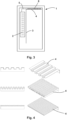
- a cold chamber 1 with a static evaporator 2 installed on one side is shown.
- a vertical baffle 3 mounted in front of the static evaporator and a horizontal baffle 4 mounted on a ceiling are visible.
- FIG. 2 is a sectional view of the cold chamber 1 according to Fig. 1
- the cold chamber 1 is shown with a static evaporator 2 installed on the side and a vertical baffle 3 mounted in front of it as well as a horizontal baffle 4 mounted on the ceiling.
- Fig. 3 is a sectional view of a cold chamber 1 including evaporator 2 and guide plates 3, 4 with integrated cooling line 5 and transfer fins 6 or transfer ribs.
- the cold chamber 1 is shown with a static evaporator 2 installed on the side and a vertical guide plate 3 mounted in front of it.
- the horizontal guide plate 4 mounted on the ceiling has an integrated cooling line 5 and transfer fins 6.
- the transfer fins 6 serve to connect the cooling line 5 to the guide plate 4 and thus provide additional cooling of the guide plate 4 using a cooling medium in the cold line 5.
- Fig. 4 a schematic representation of three design variants of a guide plate 4 is shown. Different shapes of the guide plates 3, 4 serve to increase a guide plate surface with identical external dimensions, in particular length and width, of the guide plates 3, 4.
Landscapes
- Engineering & Computer Science (AREA)
- Health & Medical Sciences (AREA)
- General Engineering & Computer Science (AREA)
- Chemical & Material Sciences (AREA)
- Thermal Sciences (AREA)
- Mechanical Engineering (AREA)
- Physics & Mathematics (AREA)
- Combustion & Propulsion (AREA)
- Public Health (AREA)
- General Health & Medical Sciences (AREA)
- Veterinary Medicine (AREA)
- Animal Behavior & Ethology (AREA)
- Life Sciences & Earth Sciences (AREA)
- Heart & Thoracic Surgery (AREA)
- Vascular Medicine (AREA)
- Biomedical Technology (AREA)
- Epidemiology (AREA)
- Pain & Pain Management (AREA)
- Physical Education & Sports Medicine (AREA)
- Rehabilitation Therapy (AREA)
- Cold Air Circulating Systems And Constructional Details In Refrigerators (AREA)
- Thermotherapy And Cooling Therapy Devices (AREA)
Description
- Die Erfindung betrifft eine Cryosauna gemäß dem Oberbegriff des Anspruchs 1.
- Des Weiteren betrifft die Erfindung ein Verfahren zur Herstellung einer Temperaturhomogenität in einer Cryosauna.
- Aus dem Stand der Technik sind Kältekammern bekannt, welche oftmals auch als Tieftemperaturkammern, Cryokammern bzw. Kryokammern oder Cryosauna bezeichnet werden. Bei derartigen Kältekammern kommen in der Regel Ventilatoren zum Einsatz, um die Luft im Inneren der Kammer umzuwälzen. Bei diesem Prinzip spricht man in Fachkreisen auch von einer Zwangsumwälzung. Die Umwälzung dient dem Zweck, das Leistungsvermögen eines Verdampfers oder Wärmetauschers bestmöglich nutzen und die Kältekammer effizient abkühlen zu können. Dabei führt die Umwälzung zu einem Ausgleich der Lufttemperatur zwischen den kältesten Bereichen der Kältekammer, welche sich zumeist nahe dem Boden bzw. dem Verdampferm oder Wärmetauscher befinden, und den wärmsten Bereichen der Kältekammer, welche oftmals nahe der Decke bzw. den am weitesten vom Verdampfer oder Wärmetauscher entfernten Bereichen der Kältekammer befinden.
- Ein Einsatz von Ventilatoren zur Umwälzung führt zu Luftbewegungen und Luftströmungsgeschwindigkeiten innerhalb der Kältekammer, die von Nutzern, welche sich in der Regel zu medizinischen Behandlungszwecken in die Kältekammer begeben, als störend empfunden werden. Zudem führen tiefe Temperaturen sowie Eis- und Schneebildung zu vermehrten Ausfällen, einer Kurzlebigkeit oder Störanfälligkeit der Ventilatoren, welche zumeist deutlich außerhalb der Spezifikationsgrenzen betrieben werden.
- Die
JP H06 51769 U - Die
DE 10 2019 104 355 U1 offenbart eine Kältesauna für die Sport- und Schmerztherapie. Die Kältesauna weist einen äußeren Behandlungsraum und einen inneren Behandlungsraum auf, wobei eine Temperatur im äußeren Behandlungsraum höher ist als im inneren Behandlungsraum. Der äußere Behandlungsraum fungiert als Kälteschild für den inneren Behandlungsraum. Zur Einstellung einer Temperatur im inneren Behandlungsraum wird Luft im Umluftbetrieb zirkuliert, wofür entsprechende Zuluft- und Abluftkanäle vorgesehen sind. - Aufgabe der Erfindung ist es, eine Cryosauna der eingangs genannten Art bereitzustellen, welche die Nachteile des Standes der Technik vermeidet und gleichzeitig eine hohe Temperaturhomogenität erzielt.
- Ein weiteres Ziel der Erfindung ist es, ein Verfahren der eingangs genannten Art entsprechend weiterzubilden.
- Diese Aufgabe wird erfindungsgemäß mit einer Cryosauna nach Anspruch 1 gelöst.
- Ein statischer Verdampfer ist ein Verdampfer, mit dem die Kühlleistung ohne Zwangsumwälzung erreicht wird. Dementsprechend werden statische Verdampfer auch als stille Verdampfer bezeichnet.
- Im Rahmen der Erfindung ist es bevorzugt, dass bei bzw. in der Kältekammer nur ein oder mehrere statische Verdampfer eingesetzt werden. Es erfolgt dann keine Zwangsumwälzung.
- Zudem wird zumindest ein Leitblech zur Optimierung der Verteilung der thermischen Energie genutzt, woraus vor allem in einem oberen Bereich der Kältekammer eine Verbesserung der Temperaturschichtung, insbesondere der Temperaturhomogenität, resultiert. Hierbei wird ein Leitblech vertikal vor dem Verdampfer bzw. Wärmetauscher angebracht und ein Leitblech horizontal nahe der Decke der Kältekammer. Zum Erreichen der Wirkung ist es jedoch unerheblich, ob es sich um zwei trennbare Leitbleche oder ein gesamtes Leitblech handelt.
- Darüber hinaus ist das Erreichen der Wirkung nicht an die Verwendung beider Leitbleche gebunden. Eine Verbesserung gegenüber dem Stand der Technik kann bereits durch die Verwendung nur eines der beiden Leitbleche, das vertikale und/oder deckennah bzw. deckennah und/oder vertikal angeordnete Leitblech, erzielt werden. Eine Trennung der Leitbleche erfolgt lediglich wegen der Einbringung in die Kältekammer.
- Ein Material bzw. eine Oberflächenbeschaffenheit der Leitbleche wirkt sich auf eine Effektivität der Leitbleche aus. Dabei verbessert sich mit einer höheren Wärmeleitfähigkeit des Materials auch die Temperaturhomogenität. Eingesetzt werden Edelstahlbleche und/oder Aluminiumbleche.
- Zudem wird die Temperaturhomogenität durch eine Ausbildung der Leitbleche mit einer möglichst großen Oberfläche positiv beeinflusst. Außenabmessungen der Leitbleche werden durch die Größe der Kältekammer beschränkt.
- Darüber hinaus wird die Temperaturhomogenität positiv beeinflusst, indem die Oberfläche der Leitbleche bei identen Außenabmessungen erhöht wird. Dies wird mit speziellen Ausformungen, insbesondere Kantungen, realisiert.
- Ein weiterer positiver Effekt auf die Temperaturhomogenität wird erzielt, indem in das Leitblech ein Kältekreis, insbesondere ein Kälterohr, eingearbeitet wird.
- Außerdem wird die Temperaturhomogenität positiv beeinflusst, indem Lamellen bzw. Rippen am Kälterohr in dem oder den Leitblechen eingearbeitet werden.
- Durch eine erfindungsgemäße Kältekammer wird die Luftbewegung ausschließlich durch natürliche Konvektion erreicht und somit auf ein physikalisches Minimum reduziert. Gleichermaßen stellt sich die niedrigste Luftströmungsgeschwindigkeit ein. Dies bietet vor allem Vorteile für Personen, welche sich beispielsweise zu medizinischen Behandlungszwecken in die Kältekammer begeben.
- Zudem wird durch die erfindungsgemäße Kältekammer die "Kälteverteilung" im Raum und damit die Temperaturhomogenität gegenüber einem Aufbau mit statischem Verdampfer ohne Leitbleche optimiert.
- Darüber hinaus wird mit einer erfindungsgemäßen Kältekammer, im Vergleich mit anderen auf dem Markt bestehenden Produkten, hinsichtlich der Raumhöhe eine niedrigste und damit optimierteste Variante erzielt.
- Außerdem werden mit einer erfindungsgemäßen Kältekammer Anlagenstörungen reduziert. Ventilatoren haben eine hohe Ausfallrate im Tieftemperaturbereich. Tiefe Temperaturen und Eis- bzw. Schneebildung führen zu vermehrten Ausfällen der Ventilatoren. Zudem geht mit diesem Einsatzbereich, welcher meist deutlich außerhalb der Spezifikationsgrenzen der Ventilatoren liegt, eine Kurzlebigkeit und Störanfälligkeit der Ventilatoren einher.
- Das verfahrensmäßige Ziel wird erreicht, wenn bei einem Verfahren der eingangs genannten Art die Temperaturhomogenität über ein vertikal vor einem statischen Verdampfer bzw.
- Wärmetauscher angeordnetes Leitblech und ein nahe einer Decke der Kältekammer angeordnetes zweites Leitblech verbessert wird. Hierbei kommen bevorzugt wiederum nur ein oder mehrere statische Verdampfer zum Einsatz.
- In den Zeichnungen ist gezeigt:
-
Fig. 1 schematische Darstellung einer Kältekammer samt Verdampfer und Leitblechen; -
Fig. 2 Schnittansicht der Kältekammer gemäßFig. 1 ; -
Fig. 3 Schnittansicht der Kältekammer samt Verdampfer und Leitblechen mit integrierter Kälteleitung und Übertragungslamellen bzw. Übertragungsrippen; -
Fig. 4 schematische Darstellungen dreier Ausführungsvarianten eines Leitbleches. - In
Fig. 1 ist eine Kältekammer 1 mit an einer Seite verbautem statischen Verdampfer 2 gezeigt. Zudem sind ein vor dem statischen Verdampfer montiertes vertikales Leitblech 3 und ein an einer Decke montiertes horizontales Leitblech 4 ersichtlich. - In der
Fig. 2 ist eine Schnittansicht der Kältekammer 1 gemäßFig. 1 dargestellt. Dabei ist die Kältekammer 1 mit an der Seite verbautem statischen Verdampfer 2 und davor montiertem vertikalen Leitblech 3 sowie an der Decke montiertem horizontalen Leitblech 4 gezeigt. - In
Fig. 3 ist die Schnittansicht einer Kältekammer 1 samt Verdampfer 2 und Leitblechen 3, 4 mit integrierter Kälteleitung 5 und Übertragungslamellen 6 bzw. Übertragungsrippen dargestellt. Hierbei ist die Kältekammer 1 mit an der Seite verbautem statischen Verdampfer 2 und davor montiertem vertikalen Leitblech 3 gezeigt. Zudem weist das an der Decke montierte horizontale Leitblech 4 eine integrierte Kälteleitung 5 und Übertragungslamellen 6 auf. Die Übertragungslamellen 6 dienen einer Anbindung der Kälteleitung 5 an das Leitblech 4 und damit einer zusätzlichen Kühlung des Leitbleches 4 durch ein Kühlmedium in der Kälteleitung 5. - In der
Fig. 4 ist eine schematische Darstellung dreier Ausführungsvarianten eines Leitbleches 4 gezeigt. Dabei dienen unterschiedliche Ausformungen der Leitbleche 3, 4 einer Erhöhung einer Leitblechoberfläche bei identen Außenabmessungen, insbesondere Länge und Breite, der Leitbleche 3, 4.
Claims (11)
- Cryosauna, welche zum Kühlen einen Verdampfer (2) und/oder Wärmetauscher und zumindest ein Leitblech (3, 4) aufweist, wobei der Verdampfer (2) als statischer Verdampfer ausgebildet ist, dadurch gekennzeichnet, dass zur Verbesserung einer Temperaturhomogenität ein erstes Leitblech (3) vertikal vor dem Verdampfer (2) bzw. Wärmetauscher und ein zweites Leitblech (4) horizontal nahe einer Decke der Cryosauna angeordnet ist.
- Cryosauna nach Anspruch 1, dadurch gekennzeichnet, dass der Verdampfer (2) und/oder Wärmetauscher an einer Wand und/oder einer Decke der Cryosauna befestigt ist.
- Cryosauna nach Anspruch 1, dadurch gekennzeichnet, dass das Leitblech (3, 4) aus einem Material mit hoher thermischer Leitfähigkeit, insbesondere Edelstahl und/oder Aluminium, gebildet ist.
- Cryosauna nach Anspruch 1, dadurch gekennzeichnet, dass die Leitbleche (3, 4) zur Erhöhung einer Oberfläche mit mehreren Kantungen versehen sind.
- Cryosauna nach Anspruch 1, dadurch gekennzeichnet, dass die Cryosauna zur Kühlung mehrere Verdampfer (2) und zur Verbesserung der Temperaturhomogenität mehrere Leitbleche (3, 4) aufweist.
- Cryosauna nach Anspruch 1, dadurch gekennzeichnet, dass das zweite Leitblech (4) eine integrierte Kälteleitung (5) aufweist.
- Cryosauna nach Anspruch 1, dadurch gekennzeichnet, dass eine Kälteleitung vorgesehen ist, welche über Lamellen (6) oder Rippen mit dem zweiten Leitblech (4) verbunden ist.
- Cryosauna nach Anspruch 7, dadurch gekennzeichnet, dass das zweite Leitblech (4) mit integrierter Kälteleitung (5) und Übertragungslamellen (6) und/oder Übertragungsrippen ausgeführt ist.
- Cryosauna nach Anspruch 8, dadurch gekennzeichnet, dass die integrierte Kälteleitung (5) über Lamellen (6) und/oder Rippen an dem zweiten Leitblech (4) angeordnet ist.
- Verfahren zur Herstellung einer Temperaturhomogenität in einer Cryosauna gemäß einem der Ansprüche 1 bis 9, dadurch gekennzeichnet, dass die Temperaturhomogenität über ein vertikal vor einem Verdampfer (2) bzw. Wärmetauscher angeordnetes erstes Leitblech (3) und ein nahe einer Decke der Kältekammer (1) angeordnetes zweites Leitblech (4) verbessert wird.
- Verfahren nach Anspruch 10, dadurch gekennzeichnet, dass zur Herstellung der Temperaturhomogenität keine Zwangsumwälzung, insbesondere nicht durch einen Ventilator, erfolgt.
Applications Claiming Priority (2)
| Application Number | Priority Date | Filing Date | Title |
|---|---|---|---|
| AT600332021A AT524726A1 (de) | 2021-02-02 | 2021-02-02 | Kältekammer |
| PCT/AT2021/060351 WO2022165543A1 (de) | 2021-02-02 | 2021-09-30 | Kältekammer |
Publications (3)
| Publication Number | Publication Date |
|---|---|
| EP4288727A1 EP4288727A1 (de) | 2023-12-13 |
| EP4288727C0 EP4288727C0 (de) | 2025-01-22 |
| EP4288727B1 true EP4288727B1 (de) | 2025-01-22 |
Family
ID=78085747
Family Applications (1)
| Application Number | Title | Priority Date | Filing Date |
|---|---|---|---|
| EP21789603.4A Active EP4288727B1 (de) | 2021-02-02 | 2021-09-30 | Cryosauna |
Country Status (3)
| Country | Link |
|---|---|
| EP (1) | EP4288727B1 (de) |
| AT (1) | AT524726A1 (de) |
| WO (1) | WO2022165543A1 (de) |
Families Citing this family (1)
| Publication number | Priority date | Publication date | Assignee | Title |
|---|---|---|---|---|
| AT524726A1 (de) * | 2021-02-02 | 2022-08-15 | Amt Kaeltetechnik Gmbh | Kältekammer |
Citations (4)
| Publication number | Priority date | Publication date | Assignee | Title |
|---|---|---|---|---|
| BE341687A (fr) * | 1927-04-08 | 1927-05-31 | Louis Costan | Chambre frigorifique ou glacière. |
| US1734127A (en) * | 1927-03-02 | 1929-11-05 | Hamilton James Telford | Refrigerating coil |
| DE202019104355U1 (de) * | 2019-08-07 | 2019-08-13 | Engie Deutschland Gmbh | Kältesauna |
| AT524726A1 (de) * | 2021-02-02 | 2022-08-15 | Amt Kaeltetechnik Gmbh | Kältekammer |
Family Cites Families (11)
| Publication number | Priority date | Publication date | Assignee | Title |
|---|---|---|---|---|
| US1794030A (en) * | 1927-02-21 | 1931-02-24 | Metropolitan Eng Co | Refrigerating machine |
| GB421145A (en) * | 1933-02-24 | 1934-12-14 | British Thomson Houston Co Ltd | Improvements in and relating to cooling units for refrigerating systems |
| BE410875A (fr) * | 1935-08-14 | 1935-09-30 | Armoire frigorifique | |
| GB468569A (en) * | 1936-01-07 | 1937-07-07 | Kelvinator Corp | Improvements in or relating to refrigerating apparatus |
| US2882701A (en) * | 1954-12-07 | 1959-04-21 | Gen Motors Corp | Refrigerating apparatus having cold air jacket |
| DE2928774C2 (de) * | 1979-07-17 | 1984-03-22 | Bosch-Siemens Hausgeräte GmbH, 7000 Stuttgart | Gefrierschrank mit einem durch natürliche Konvektion gekühlten, großräumigen Gefrierraum |
| JPH0651769U (ja) * | 1992-12-10 | 1994-07-15 | 株式会社東洋製作所 | 冷蔵倉庫 |
| DE19917974C2 (de) * | 1999-04-21 | 2001-04-05 | Aeg Hausgeraete Gmbh | Kühl- und/oder Gefriergerät mit einem im Innenraum angeordneten kältegenerierenden Bauteil |
| JP4131549B2 (ja) * | 2004-07-20 | 2008-08-13 | 株式会社前川製作所 | 冷凍漁船用低温保冷庫 |
| WO2013184019A1 (ru) * | 2012-06-07 | 2013-12-12 | Erganokov Khasanbi Khabievich | Установка для общей воздушной криотерапии |
| WO2018186851A1 (en) * | 2017-04-05 | 2018-10-11 | Lovett Jared | Device and method of use for equine whole-body cryotherapy |
-
2021
- 2021-02-02 AT AT600332021A patent/AT524726A1/de not_active Application Discontinuation
- 2021-09-30 WO PCT/AT2021/060351 patent/WO2022165543A1/de not_active Ceased
- 2021-09-30 EP EP21789603.4A patent/EP4288727B1/de active Active
Patent Citations (4)
| Publication number | Priority date | Publication date | Assignee | Title |
|---|---|---|---|---|
| US1734127A (en) * | 1927-03-02 | 1929-11-05 | Hamilton James Telford | Refrigerating coil |
| BE341687A (fr) * | 1927-04-08 | 1927-05-31 | Louis Costan | Chambre frigorifique ou glacière. |
| DE202019104355U1 (de) * | 2019-08-07 | 2019-08-13 | Engie Deutschland Gmbh | Kältesauna |
| AT524726A1 (de) * | 2021-02-02 | 2022-08-15 | Amt Kaeltetechnik Gmbh | Kältekammer |
Also Published As
| Publication number | Publication date |
|---|---|
| EP4288727C0 (de) | 2025-01-22 |
| WO2022165543A1 (de) | 2022-08-11 |
| AT524726A1 (de) | 2022-08-15 |
| EP4288727A1 (de) | 2023-12-13 |
Similar Documents
| Publication | Publication Date | Title |
|---|---|---|
| EP2798285B1 (de) | Haushaltskältegerät mit einem kaltlagerfach | |
| EP3221646A1 (de) | Verfahren und anordnung zum klimatisieren eines kaltganges | |
| WO2022165543A1 (de) | Kältekammer | |
| DE102010000956A1 (de) | Wärmeübertrageranordnung | |
| DE202019104355U1 (de) | Kältesauna | |
| DE102017005226A1 (de) | Sockelkonzept | |
| DE10393127B4 (de) | Kühlaggregat(e), Verfahren zum Kühlen und Kühlanordnung | |
| EP2837275B1 (de) | Kühlgerät für einen schaltschrank sowie ein entsprechendes verfahren | |
| EP1256770B1 (de) | Luftgekühlter Verflüssiger oder luftbeheizter Verdampfer | |
| DE3731800C2 (de) | Einrichtung zur Kühlung von Räumen | |
| DE102010030683B4 (de) | Kühlanordnung für einen Schrank zur Installation von IT-, EDV-, Netzwerk- und/oder Telekommunikationssystemen und Verfahren zum Kühlen eines solchen Schranks | |
| DE102015101022B3 (de) | Rechenzentrum | |
| EP3430949B1 (de) | Kühlmöbel | |
| EP0508176A2 (de) | Anordnung zum Abführen von Wärmelasten | |
| DE202016107184U1 (de) | Wärmetauschereinrichtung | |
| DE1946787C3 (de) | Kühltheke mit Umwälzung der Kühlluft | |
| EP2637488B1 (de) | Klimagerät zur Kühlung von Elektronikgeräten oder Elektronikgeräteschränken mit Ausblasgitter | |
| DE102019121383B3 (de) | Kältesauna | |
| DE102021126550B4 (de) | Rechenzentrum mit einer in einem Container angeordneten Schaltschrankreihe und einer Kaltgang-Warmgang-Schottung | |
| DE636683C (de) | Vorrichtung zur Luftkuehlung waermeabgebender Teile von Kaelteapparaten o. dgl. | |
| CH708943A1 (de) | Kühlgerät mit Kondensationsschutz. | |
| EP1467164A1 (de) | Tiefkühltruhe | |
| DE19509312A1 (de) | Verfahren zur Raumkühlung | |
| DE4223031C2 (de) | Vorrichtung zur Kühlung von Räumen | |
| DE102022002261A1 (de) | Klimaanlage |
Legal Events
| Date | Code | Title | Description |
|---|---|---|---|
| STAA | Information on the status of an ep patent application or granted ep patent |
Free format text: STATUS: UNKNOWN |
|
| STAA | Information on the status of an ep patent application or granted ep patent |
Free format text: STATUS: THE INTERNATIONAL PUBLICATION HAS BEEN MADE |
|
| PUAI | Public reference made under article 153(3) epc to a published international application that has entered the european phase |
Free format text: ORIGINAL CODE: 0009012 |
|
| STAA | Information on the status of an ep patent application or granted ep patent |
Free format text: STATUS: REQUEST FOR EXAMINATION WAS MADE |
|
| 17P | Request for examination filed |
Effective date: 20230621 |
|
| AK | Designated contracting states |
Kind code of ref document: A1 Designated state(s): AL AT BE BG CH CY CZ DE DK EE ES FI FR GB GR HR HU IE IS IT LI LT LU LV MC MK MT NL NO PL PT RO RS SE SI SK SM TR |
|
| DAV | Request for validation of the european patent (deleted) | ||
| DAX | Request for extension of the european patent (deleted) | ||
| STAA | Information on the status of an ep patent application or granted ep patent |
Free format text: STATUS: EXAMINATION IS IN PROGRESS |
|
| STAA | Information on the status of an ep patent application or granted ep patent |
Free format text: STATUS: REQUEST FOR EXAMINATION WAS MADE |
|
| 17Q | First examination report despatched |
Effective date: 20240910 |
|
| GRAP | Despatch of communication of intention to grant a patent |
Free format text: ORIGINAL CODE: EPIDOSNIGR1 |
|
| STAA | Information on the status of an ep patent application or granted ep patent |
Free format text: STATUS: GRANT OF PATENT IS INTENDED |
|
| GRAJ | Information related to disapproval of communication of intention to grant by the applicant or resumption of examination proceedings by the epo deleted |
Free format text: ORIGINAL CODE: EPIDOSDIGR1 |
|
| STAA | Information on the status of an ep patent application or granted ep patent |
Free format text: STATUS: REQUEST FOR EXAMINATION WAS MADE |
|
| GRAP | Despatch of communication of intention to grant a patent |
Free format text: ORIGINAL CODE: EPIDOSNIGR1 |
|
| STAA | Information on the status of an ep patent application or granted ep patent |
Free format text: STATUS: GRANT OF PATENT IS INTENDED |
|
| INTG | Intention to grant announced |
Effective date: 20241017 |
|
| INTC | Intention to grant announced (deleted) | ||
| GRAS | Grant fee paid |
Free format text: ORIGINAL CODE: EPIDOSNIGR3 |
|
| INTG | Intention to grant announced |
Effective date: 20241111 |
|
| GRAA | (expected) grant |
Free format text: ORIGINAL CODE: 0009210 |
|
| STAA | Information on the status of an ep patent application or granted ep patent |
Free format text: STATUS: THE PATENT HAS BEEN GRANTED |
|
| RAP3 | Party data changed (applicant data changed or rights of an application transferred) |
Owner name: KXR KAELTE + ANLAGENTECHNIK GMBH |
|
| AK | Designated contracting states |
Kind code of ref document: B1 Designated state(s): AL AT BE BG CH CY CZ DE DK EE ES FI FR GB GR HR HU IE IS IT LI LT LU LV MC MK MT NL NO PL PT RO RS SE SI SK SM TR |
|
| REG | Reference to a national code |
Ref country code: GB Ref legal event code: FG4D Free format text: NOT ENGLISH |
|
| REG | Reference to a national code |
Ref country code: CH Ref legal event code: EP |
|
| REG | Reference to a national code |
Ref country code: IE Ref legal event code: FG4D Free format text: LANGUAGE OF EP DOCUMENT: GERMAN |
|
| REG | Reference to a national code |
Ref country code: DE Ref legal event code: R096 Ref document number: 502021006477 Country of ref document: DE |
|
| U01 | Request for unitary effect filed |
Effective date: 20250203 |
|
| U07 | Unitary effect registered |
Designated state(s): AT BE BG DE DK EE FI FR IT LT LU LV MT NL PT RO SE SI Effective date: 20250207 |
|
| PG25 | Lapsed in a contracting state [announced via postgrant information from national office to epo] |
Ref country code: RS Free format text: LAPSE BECAUSE OF FAILURE TO SUBMIT A TRANSLATION OF THE DESCRIPTION OR TO PAY THE FEE WITHIN THE PRESCRIBED TIME-LIMIT Effective date: 20250422 |
|
| PG25 | Lapsed in a contracting state [announced via postgrant information from national office to epo] |
Ref country code: PL Free format text: LAPSE BECAUSE OF FAILURE TO SUBMIT A TRANSLATION OF THE DESCRIPTION OR TO PAY THE FEE WITHIN THE PRESCRIBED TIME-LIMIT Effective date: 20250122 |
|
| PG25 | Lapsed in a contracting state [announced via postgrant information from national office to epo] |
Ref country code: ES Free format text: LAPSE BECAUSE OF FAILURE TO SUBMIT A TRANSLATION OF THE DESCRIPTION OR TO PAY THE FEE WITHIN THE PRESCRIBED TIME-LIMIT Effective date: 20250122 |
|
| PG25 | Lapsed in a contracting state [announced via postgrant information from national office to epo] |
Ref country code: IS Free format text: LAPSE BECAUSE OF FAILURE TO SUBMIT A TRANSLATION OF THE DESCRIPTION OR TO PAY THE FEE WITHIN THE PRESCRIBED TIME-LIMIT Effective date: 20250522 Ref country code: NO Free format text: LAPSE BECAUSE OF FAILURE TO SUBMIT A TRANSLATION OF THE DESCRIPTION OR TO PAY THE FEE WITHIN THE PRESCRIBED TIME-LIMIT Effective date: 20250422 |
|
| PG25 | Lapsed in a contracting state [announced via postgrant information from national office to epo] |
Ref country code: HR Free format text: LAPSE BECAUSE OF FAILURE TO SUBMIT A TRANSLATION OF THE DESCRIPTION OR TO PAY THE FEE WITHIN THE PRESCRIBED TIME-LIMIT Effective date: 20250122 |
|
| PG25 | Lapsed in a contracting state [announced via postgrant information from national office to epo] |
Ref country code: GR Free format text: LAPSE BECAUSE OF FAILURE TO SUBMIT A TRANSLATION OF THE DESCRIPTION OR TO PAY THE FEE WITHIN THE PRESCRIBED TIME-LIMIT Effective date: 20250423 |
|
| U20 | Renewal fee for the european patent with unitary effect paid |
Year of fee payment: 5 Effective date: 20250814 |
|
| PG25 | Lapsed in a contracting state [announced via postgrant information from national office to epo] |
Ref country code: SM Free format text: LAPSE BECAUSE OF FAILURE TO SUBMIT A TRANSLATION OF THE DESCRIPTION OR TO PAY THE FEE WITHIN THE PRESCRIBED TIME-LIMIT Effective date: 20250122 |
|
| PG25 | Lapsed in a contracting state [announced via postgrant information from national office to epo] |
Ref country code: CZ Free format text: LAPSE BECAUSE OF FAILURE TO SUBMIT A TRANSLATION OF THE DESCRIPTION OR TO PAY THE FEE WITHIN THE PRESCRIBED TIME-LIMIT Effective date: 20250122 |
|
| PG25 | Lapsed in a contracting state [announced via postgrant information from national office to epo] |
Ref country code: SK Free format text: LAPSE BECAUSE OF FAILURE TO SUBMIT A TRANSLATION OF THE DESCRIPTION OR TO PAY THE FEE WITHIN THE PRESCRIBED TIME-LIMIT Effective date: 20250122 |
|
| PLBE | No opposition filed within time limit |
Free format text: ORIGINAL CODE: 0009261 |
|
| STAA | Information on the status of an ep patent application or granted ep patent |
Free format text: STATUS: NO OPPOSITION FILED WITHIN TIME LIMIT |
|
| REG | Reference to a national code |
Ref country code: CH Ref legal event code: L10 Free format text: ST27 STATUS EVENT CODE: U-0-0-L10-L00 (AS PROVIDED BY THE NATIONAL OFFICE) Effective date: 20251203 |
|
| 26N | No opposition filed |
Effective date: 20251023 |
|
| REG | Reference to a national code |
Ref country code: CH Ref legal event code: H13 Free format text: ST27 STATUS EVENT CODE: U-0-0-H10-H13 (AS PROVIDED BY THE NATIONAL OFFICE) Effective date: 20260504 |