EP4286240B1 - Elektrokontaktkupplung - Google Patents
Elektrokontaktkupplung Download PDFInfo
- Publication number
- EP4286240B1 EP4286240B1 EP23175805.3A EP23175805A EP4286240B1 EP 4286240 B1 EP4286240 B1 EP 4286240B1 EP 23175805 A EP23175805 A EP 23175805A EP 4286240 B1 EP4286240 B1 EP 4286240B1
- Authority
- EP
- European Patent Office
- Prior art keywords
- coupling
- electrical contact
- protective flap
- contact coupling
- movement
- Prior art date
- Legal status (The legal status is an assumption and is not a legal conclusion. Google has not performed a legal analysis and makes no representation as to the accuracy of the status listed.)
- Active
Links
Images


Classifications
-
- B—PERFORMING OPERATIONS; TRANSPORTING
- B61—RAILWAYS
- B61G—COUPLINGS; DRAUGHT AND BUFFING APPLIANCES
- B61G5/00—Couplings for special purposes not otherwise provided for
- B61G5/06—Couplings for special purposes not otherwise provided for for, or combined with, couplings or connectors for fluid conduits or electric cables
- B61G5/10—Couplings for special purposes not otherwise provided for for, or combined with, couplings or connectors for fluid conduits or electric cables for electric cables
Definitions
- the present invention relates to an electrical contact coupling for an automatic central buffer coupling of a rail vehicle, comprising a coupling housing in which an electrical interface unit with at least one connection contact is housed.
- the connection contact is accessible via a protective flap pivotably arranged relative to the coupling housing for covering or opening a front access to the connection contacts.
- an actuating mechanism connected to the protective flap is provided.
- the invention also relates to a central buffer coupling for rail vehicles with a mechanical contact coupling, in particular a Scharfenberg-type coupling, which also includes such an electrical contact coupling.
- the field of application of the invention extends to rail vehicles that can be assembled from individual carriages to form a train.
- the coupling provided for this purpose between the carriages is designed as an automatic center buffer coupling.
- Automatic center buffer couplings are used in particular for train sets to avoid manual coupling by automatically establishing the mechanical connection between carriages during shunting by driving them together using a spring mechanism or the like.
- air and electrical lines can be coupled if pneumatic or electrical auxiliary power or electrical data transmission is required for train operation.
- the present invention is dedicated to an electrical contact coupling provided for this purpose with at least one electrical connection contact.
- conventional electrical contact couplings for the automatic central buffer couplings of interest here are usually arranged adjacent to the same and have a coupling housing in which an electrical interface unit with the electrical connection contacts is housed.
- Such an electrical contact coupling usually has a frontal protective cover, which can be adjusted via an actuating mechanism between a first position in which the protective cover covers the frontal access and a second position in which the protective cover opens the frontal access.
- the problem is solved based on an electrical contact coupling according to the preamble of claim 1 in conjunction with its characterizing features.
- the subordinate claim 14 specifies a central buffer coupling for rail vehicles with a mechanical contact coupling, which is equipped with such an electrical contact coupling.
- the invention includes the technical teaching that the actuating mechanism for the protective flap of the electrical contact coupling has an actuating plunger arranged adjacent to the front access and protruding in this respect, which plunger has at least one rear toothed section which, designed as a push rod gear, generates on the one hand a pivoting movement for the protective flap and on the other hand a movement-coordinated feed movement for the coupling housing for electrical contacting of the connection contacts.
- the advantage of the inventive solution lies in the fact that the robust actuating mechanism forces the protective flap to open during coupling under all relevant operating and environmental conditions. Thanks to the implemented feed movement, it enables electrical contact over a relatively long contact pin length, thus virtually eliminating electrical contact failures.
- the inventive, functionally integrated actuating mechanism is based on a spring-supported pushrod gear. Tests have shown that the inventive solution functions smoothly even with a horizontal deviation of the wagons to be coupled, resulting from a tight curve radius of up to 75 meters, and with a vertical deviation of up to 1.5 degrees.
- its actuating plunger for carrying out the pivoting movement for the protective flap has a front toothed section in the form of at least one driving tooth, which interacts with a driving wheel rotatably connected to the pivot axis of the protective flap.
- the pivoting movement is thus triggered, instead of by abutting contact with the protective flap, by abutting contact with the actuating plunger, which protrudes beyond the protective flap in the unactuated initial state, thus preventing damage to the protective flap.
- the protective flap is preferably held in the end position by at least one spring element arranged on its axis in order to prevent unintentional manual opening.
- the protective cover can be designed to be quite compact compared to the state of the art. In principle, it only needs to be dimensioned large enough to cover the preferably rectangular front opening for access to the connection contacts.
- the actuating tappet has a rear toothed section in the form of a rack for functionally implementing the feed movement for the clutch housing.
- This toothed section interacts with a drive wheel to generate a drive torque for the feed movement.
- the drive wheel in the subsequent power flow, preferably drives a camshaft extending transversely to the actuating tappet, the at least one drive cam of which interacts with the clutch housing in such a way that the latter can be linearly adjusted in the feed direction and in the opposite direction.
- the coupling housing is mounted on a support frame, preferably longitudinally displaceable, to execute the linear feed movement.
- the support frame is preferably fixedly attached to the center buffer coupling.
- the connection can be implemented via a rubber mount or similar.
- At least one compression spring between, for example, the support frame or the center buffer coupling and the rear end of the coupling housing in such a way that the latter is subjected to rearward pressure.
- the at least one compression spring also supports the propulsion for the feed movement.
- At least one additional spring namely a return spring, preferably designed as a tension spring, be arranged between the support frame and the proximal end of the actuating plunger, which generates a plunger return force. This ensures that the actuating plunger is completely returned to its original position after decoupling, and that the protective flap is completely closed.
- the drive cam of the camshaft has such an asymmetrical curved shape for carrying out the feed movement that, in the movement sequence of the tappet movement, a return movement of the coupling housing is initially realized to lift the front access from the protective flap, in order to subsequently enable the protective flap to be opened via the front toothed section of the actuating tappet.
- the feed movement of the coupling housing can then be carried out for electrical contact with a mating electrical contact coupling. Thanks to the initial return movement of the coupling housing, it lifts slightly from the covering protective flap. Since an elastomer seal is preferably arranged between the two components to protect the internal electrical connection contacts from external environmental influences, damage to the elastomer seal as a result of the subsequent pivoting movement of the protective flap can be advantageously avoided.
- the curved shape of the drive cam is designed such that a rotation angle of between 45 and 65 degrees is carried out for the initial return movement, with a return path of 5 to 15 millimeters being carried out. This is sufficient to reliably lift the protective flap from an elastomer seal of the coupling housing without it being damaged by the subsequent pivoting movement.
- the pivoting movement is preferably carried out over a rotation angle of between 60 and 80 degrees for the subsequent cover opening. In this case, the coupling housing is not moved any further, so that during the standstill time, the protective flap is moved via the push rod gear. can be pivoted.
- a subsequent rotation angle of between 80 and 120 degrees then serves as the final feed movement of the coupling housing for the purpose of electrical contact.
- the feed movement is preferably in a range between 3 and 12 millimeters.
- the protective flap be hinged to the support frame of the electrical contact coupling and driven by a transmission gear arranged thereon.
- the transmission gear is preferably designed as a spur gear and provides a high-speed transmission so that a slight travel of the toothed section of the actuating plunger is sufficient to fully open the protective flap via the toothed engagement of the gear parts.
- the actuating plunger arranged on the front of the support frame be paired with an outwardly curved pressure plate arranged on the front of the support frame opposite the protective flap and designed to actuate a mating electrical contact coupling.
- This structural arrangement ensures that corresponding electrical contact couplings reliably actuate each other.
- the outwardly curved pressure plate for actuating the mating electrical contact coupling ensures reliable operation even in the event of horizontal and/or vertical angular deviations.
- the coupling housing can also have at least one centering pin or similar protruding from the front for precise contact positioning relative to the mating electrical contact coupling.
- the protruding centering pin only needs to be long enough to positively engage with a correspondingly designed component of the mating electrical contact coupling shortly before the electrical contact of the connection contacts is made during the feed movement of the coupling housing.
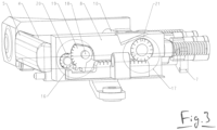
- An automatic central buffer coupling 1 of a rail vehicle (not shown in detail) consists of a known mechanical contact coupling of the Scharfenberg type, which is equipped with an additional electrical contact coupling 2 for the electrical power and/or signal supply of coupled rail vehicles.
- the electrical contact coupling is arranged above a mechanical coupling head 3 of the central buffer coupling 1 in terms of its installation position.
- the electrical contact coupling 2 comprises a coupling housing 4 with a protective flap 5 arranged pivotably opposite it for covering or opening a front access 6 to an electrical control unit (not shown in detail here).
- the protective flap 5 is connected to an actuating mechanism comprising an actuating plunger 7 arranged adjacent to the front access 6 and projecting in relation to it.
- the actuating plunger 7 is guided along its actuating path by a support frame 8.
- the protective flap 5 is also hinged to the support frame 8.
- the actuating plunger 7, arranged on the front of the support frame 8 and guided thereby, is paired with an outwardly curved pressure plate 9 arranged on the front of the support frame opposite the protective flap 5 and intended to actuate a counter-electrical contact coupling (not shown in detail).
- a camshaft 10 extends transversely to the actuating plunger 7, the drive cam 11 of which is provided for linear adjustment of the clutch housing 4 relative to the stationary support frame 8.
- Two compression springs 12a and 12b apply a feed force to the rear of the linearly adjustable clutch housing 4, minimizing the play of the cam drive.
- the coupling housing 4 is also equipped with a centering pin 14 protruding from the front, which runs axially parallel to the actuating plunger 7 and is not longitudinally adjustable.
- the centering pin serves to ensure precise contact positioning relative to the mating electrical contact coupling.
- the support frame 8 is detachably attached to the central buffer coupling (not shown here) via several rubber bearings 15 (exemplary).
- the actuating plunger 7 has two rear toothed sections 16 and 17, which are part of a push rod gear, in order to generate, on the one hand, a pivoting movement for the protective flap 5 and, on the other hand, a movement-coordinated feed movement for the coupling housing 4 for the purpose of electrical contact.
- the front toothing section 16 is designed in the form of a driving tooth, which interacts with a driving wheel 19 rotatably connected to a pivot axis 18 of the protective flap 5.
- the protective flap 5, which is hinged to the support frame 8, is not actuated directly via the driving wheel 19, but rather via an intermediate transmission gear 20, which is designed as a spur gear.
- the rear toothed section 17 of the actuating tappet 7 which is designed in the form of a rack, serves to carry out the feed movement.
- the rear toothed section 17 of the actuating tappet 7 meshes with the drive gear 21 of the camshaft 10.
- An elastomer seal 22 is arranged between the protective flap 5 and the front access 6 to the coupling housing 4 for the sealed protection of internal electrical connection contacts 23 (as an example).
- the electrical connection contacts 23 are part of the electrical interface unit 24 already mentioned above.
- the functioning of the above-described actuating mechanism according to the invention is explained below using a complete movement sequence based on the Fig. 5a to 5d described:
- the Fig. 5a shows the initial state of the actuating mechanism, in which the protective flap 5 is completely closed and the actuating plunger 7 is completely extended.
- actuating tappet 7 After contact with a counter-electrical contact coupling, the actuating tappet 7 is retracted, which initially causes a return movement of the coupling housing 4 to lift the front access - not further visible here - from the protective flap 5. This takes place here via a rotation angle of approximately 57 degrees by meshing the rear toothed section 17 with the drive gear 21 of the camshaft 10.
- the pushrod transmission can also be equipped with other transmission means on the output side to carry out the described movement cycle.
- a cam drive for moving the clutch housing is not mandatory and can also be replaced by a lever mechanism or the like.
Landscapes
- Engineering & Computer Science (AREA)
- Mechanical Engineering (AREA)
- Transmission Devices (AREA)
Applications Claiming Priority (1)
| Application Number | Priority Date | Filing Date | Title |
|---|---|---|---|
| DE102022113826.7A DE102022113826A1 (de) | 2022-06-01 | 2022-06-01 | Elektrokontaktkupplung |
Publications (2)
| Publication Number | Publication Date |
|---|---|
| EP4286240A1 EP4286240A1 (de) | 2023-12-06 |
| EP4286240B1 true EP4286240B1 (de) | 2025-03-12 |
Family
ID=86605170
Family Applications (1)
| Application Number | Title | Priority Date | Filing Date |
|---|---|---|---|
| EP23175805.3A Active EP4286240B1 (de) | 2022-06-01 | 2023-05-26 | Elektrokontaktkupplung |
Country Status (3)
| Country | Link |
|---|---|
| EP (1) | EP4286240B1 (pl) |
| DE (1) | DE102022113826A1 (pl) |
| PL (1) | PL4286240T3 (pl) |
Families Citing this family (2)
| Publication number | Priority date | Publication date | Assignee | Title |
|---|---|---|---|---|
| WO2025140802A1 (de) * | 2023-12-27 | 2025-07-03 | Voith Patent Gmbh | Elektrokontaktkupplung für eine automatische mittelpufferkupplung eines spurgeführten fahrzeugs |
| DE102024107118A1 (de) * | 2024-03-13 | 2025-09-18 | Voith Patent Gmbh | Elektrokontaktkupplung und automatische Zugkupplung |
Family Cites Families (6)
| Publication number | Priority date | Publication date | Assignee | Title |
|---|---|---|---|---|
| US1659551A (en) * | 1921-05-09 | 1928-02-14 | Herbert E Van Dorn | Electric coupler |
| US1733196A (en) * | 1927-02-24 | 1929-10-29 | Westinghouse Air Brake Co | Electric coupling |
| US3385454A (en) * | 1966-06-27 | 1968-05-28 | Westinghouse Air Brake Co | Automatic air and electric railway car coupler |
| US3438511A (en) * | 1967-09-06 | 1969-04-15 | Dresser Ind | Electric coupler cover assembly |
| DE19921611A1 (de) | 1999-05-10 | 2000-11-23 | Knorr Bremse Systeme | Elektrokuppeleinrichtung für eine automatische Zugkupplung |
| DE102019132642A1 (de) | 2019-12-02 | 2021-06-02 | Voith Patent Gmbh | Elektrokontaktkupplung und Mittelpufferkupplung für ein Schienenfahrzeug |
-
2022
- 2022-06-01 DE DE102022113826.7A patent/DE102022113826A1/de active Pending
-
2023
- 2023-05-26 EP EP23175805.3A patent/EP4286240B1/de active Active
- 2023-05-26 PL PL23175805.3T patent/PL4286240T3/pl unknown
Also Published As
| Publication number | Publication date |
|---|---|
| PL4286240T3 (pl) | 2025-05-05 |
| DE102022113826A1 (de) | 2023-12-07 |
| EP4286240A1 (de) | 2023-12-06 |
Similar Documents
| Publication | Publication Date | Title |
|---|---|---|
| EP4286240B1 (de) | Elektrokontaktkupplung | |
| DE102020209607B4 (de) | Verschlussanordnung zum Verschließen einer Tankmulde einer Karosserie eines Kraftfahrzeugs | |
| EP4019312B1 (de) | Abdeckvorrichtung, insbesondere ladeklappenvorrichtung, mit einer deckelkomponente zum verschliessen und freigeben einer öffnung in einer fahrzeugkarosserie | |
| EP3795787B1 (de) | Zweiflügelige fahrzeugtürvorrichtung mit vorverriegelung eines voreilenden türflügels | |
| DE102020131792B3 (de) | Linearaktuator | |
| EP4166366B1 (de) | Klappeneinheit für eine öffnung an einem fahrzeug und fahrzeug | |
| DE102022100947A1 (de) | Türscharniervorrichtung eines Fahrzeuges | |
| DE102021111573A1 (de) | Abdeckvorrichtung, insbesondere ladeklappenvorrichtung, mit einer deckelkomponente zum verschliessen und freigeben einer öffnung in einer fahrzeugkarosserie | |
| EP1767427A1 (de) | Einrichtung zur Bewegung des Türblattes einer Schwenkschiebetür, insbesondere für Schienenfahrzeuge | |
| DE102009018188A1 (de) | Vorrichtung zum automatischen Schließen einer Fahrzeugtür | |
| EP2129540B1 (de) | Öffnungsfähiges fahrzeugdach mit einer betätigungseinrichtung für ein bewegbares dachelement | |
| DE102004048405B4 (de) | Kinematik zum Verstellen einer Seitenklappe einer Abdeckanordnung für Fahrzeuge mit öffnungsfähigem Fahrzeugdach | |
| EP2428381B1 (de) | Verschlusseinrichtung | |
| WO2023148331A1 (de) | ÖFFNUNGS- UND SCHLIEßVORRICHTUNG FÜR EIN KRAFTFAHRZEUG | |
| DE202005000559U1 (de) | Antriebsanordnung zur Betätigung der Klappe eines Kraftfahrzeugs | |
| DE102009016399A1 (de) | Öffnungsvorrichtung für Schwenkschiebetüren | |
| EP4077854B1 (de) | Türantrieb für eine kraftfahrzeugtür oder kraftfahrzeugklappe | |
| DE102005033098A1 (de) | Heckklappe für ein Kraftfahrzeug | |
| DE102019101068A1 (de) | Antriebsanordnung zur Verstellung eines Verstellelements eines Kraftfahrzeugs | |
| EP3059136A1 (de) | Schienenfahrzeug und aussenspiegelvorrichtung | |
| DE102022118360A1 (de) | Automatische Zugkupplung, Schienenfahrzeug mit einer automatischen Zugkupplung und Verfahren zum Kuppeln und Entkuppeln einer automatischen Zugkupplung | |
| EP2357103B1 (de) | Verschluss für einen Verdeckkastendeckel eines Cabriolet-Fahrzeugs | |
| DE102013009921A1 (de) | Türantrieb für eine Schwenkschiebetür eines Fahrzeugs | |
| DE102019115965A1 (de) | Antriebsanordnung zur motorischen Verstellung einer Klappe eines Kraftfahrzeugs | |
| WO2018233898A1 (de) | Kupplungskopf einer automatischen mittelpufferkupplung |
Legal Events
| Date | Code | Title | Description |
|---|---|---|---|
| PUAI | Public reference made under article 153(3) epc to a published international application that has entered the european phase |
Free format text: ORIGINAL CODE: 0009012 |
|
| STAA | Information on the status of an ep patent application or granted ep patent |
Free format text: STATUS: THE APPLICATION HAS BEEN PUBLISHED |
|
| AK | Designated contracting states |
Kind code of ref document: A1 Designated state(s): AL AT BE BG CH CY CZ DE DK EE ES FI FR GB GR HR HU IE IS IT LI LT LU LV MC ME MK MT NL NO PL PT RO RS SE SI SK SM TR |
|
| STAA | Information on the status of an ep patent application or granted ep patent |
Free format text: STATUS: REQUEST FOR EXAMINATION WAS MADE |
|
| 17P | Request for examination filed |
Effective date: 20240606 |
|
| RBV | Designated contracting states (corrected) |
Designated state(s): AL AT BE BG CH CY CZ DE DK EE ES FI FR GB GR HR HU IE IS IT LI LT LU LV MC ME MK MT NL NO PL PT RO RS SE SI SK SM TR |
|
| GRAP | Despatch of communication of intention to grant a patent |
Free format text: ORIGINAL CODE: EPIDOSNIGR1 |
|
| STAA | Information on the status of an ep patent application or granted ep patent |
Free format text: STATUS: GRANT OF PATENT IS INTENDED |
|
| INTG | Intention to grant announced |
Effective date: 20241023 |
|
| GRAS | Grant fee paid |
Free format text: ORIGINAL CODE: EPIDOSNIGR3 |
|
| GRAA | (expected) grant |
Free format text: ORIGINAL CODE: 0009210 |
|
| STAA | Information on the status of an ep patent application or granted ep patent |
Free format text: STATUS: THE PATENT HAS BEEN GRANTED |
|
| AK | Designated contracting states |
Kind code of ref document: B1 Designated state(s): AL AT BE BG CH CY CZ DE DK EE ES FI FR GB GR HR HU IE IS IT LI LT LU LV MC ME MK MT NL NO PL PT RO RS SE SI SK SM TR |
|
| REG | Reference to a national code |
Ref country code: GB Ref legal event code: FG4D Free format text: NOT ENGLISH |
|
| REG | Reference to a national code |
Ref country code: CH Ref legal event code: EP |
|
| REG | Reference to a national code |
Ref country code: DE Ref legal event code: R096 Ref document number: 502023000673 Country of ref document: DE |
|
| P01 | Opt-out of the competence of the unified patent court (upc) registered |
Free format text: CASE NUMBER: APP_10953/2025 Effective date: 20250305 |
|
| REG | Reference to a national code |
Ref country code: IE Ref legal event code: FG4D Free format text: LANGUAGE OF EP DOCUMENT: GERMAN |
|
| REG | Reference to a national code |
Ref country code: NL Ref legal event code: FP |
|
| REG | Reference to a national code |
Ref country code: SE Ref legal event code: TRGR |
|
| PG25 | Lapsed in a contracting state [announced via postgrant information from national office to epo] |
Ref country code: RS Free format text: LAPSE BECAUSE OF FAILURE TO SUBMIT A TRANSLATION OF THE DESCRIPTION OR TO PAY THE FEE WITHIN THE PRESCRIBED TIME-LIMIT Effective date: 20250612 |
|
| PG25 | Lapsed in a contracting state [announced via postgrant information from national office to epo] |
Ref country code: FI Free format text: LAPSE BECAUSE OF FAILURE TO SUBMIT A TRANSLATION OF THE DESCRIPTION OR TO PAY THE FEE WITHIN THE PRESCRIBED TIME-LIMIT Effective date: 20250312 |
|
| PGFP | Annual fee paid to national office [announced via postgrant information from national office to epo] |
Ref country code: DE Payment date: 20250528 Year of fee payment: 3 Ref country code: PL Payment date: 20250505 Year of fee payment: 3 |
|
| PG25 | Lapsed in a contracting state [announced via postgrant information from national office to epo] |
Ref country code: ES Free format text: LAPSE BECAUSE OF FAILURE TO SUBMIT A TRANSLATION OF THE DESCRIPTION OR TO PAY THE FEE WITHIN THE PRESCRIBED TIME-LIMIT Effective date: 20250312 |
|
| REG | Reference to a national code |
Ref country code: LT Ref legal event code: MG9D |
|
| PG25 | Lapsed in a contracting state [announced via postgrant information from national office to epo] |
Ref country code: NO Free format text: LAPSE BECAUSE OF FAILURE TO SUBMIT A TRANSLATION OF THE DESCRIPTION OR TO PAY THE FEE WITHIN THE PRESCRIBED TIME-LIMIT Effective date: 20250612 |
|
| PGFP | Annual fee paid to national office [announced via postgrant information from national office to epo] |
Ref country code: IT Payment date: 20250531 Year of fee payment: 3 |
|
| PG25 | Lapsed in a contracting state [announced via postgrant information from national office to epo] |
Ref country code: HR Free format text: LAPSE BECAUSE OF FAILURE TO SUBMIT A TRANSLATION OF THE DESCRIPTION OR TO PAY THE FEE WITHIN THE PRESCRIBED TIME-LIMIT Effective date: 20250312 |
|
| PG25 | Lapsed in a contracting state [announced via postgrant information from national office to epo] |
Ref country code: LV Free format text: LAPSE BECAUSE OF FAILURE TO SUBMIT A TRANSLATION OF THE DESCRIPTION OR TO PAY THE FEE WITHIN THE PRESCRIBED TIME-LIMIT Effective date: 20250312 |
|
| PGFP | Annual fee paid to national office [announced via postgrant information from national office to epo] |
Ref country code: FR Payment date: 20250526 Year of fee payment: 3 |
|
| PG25 | Lapsed in a contracting state [announced via postgrant information from national office to epo] |
Ref country code: BG Free format text: LAPSE BECAUSE OF FAILURE TO SUBMIT A TRANSLATION OF THE DESCRIPTION OR TO PAY THE FEE WITHIN THE PRESCRIBED TIME-LIMIT Effective date: 20250312 Ref country code: GR Free format text: LAPSE BECAUSE OF FAILURE TO SUBMIT A TRANSLATION OF THE DESCRIPTION OR TO PAY THE FEE WITHIN THE PRESCRIBED TIME-LIMIT Effective date: 20250613 |
|
| PGFP | Annual fee paid to national office [announced via postgrant information from national office to epo] |
Ref country code: AT Payment date: 20250721 Year of fee payment: 3 |
|
| PGFP | Annual fee paid to national office [announced via postgrant information from national office to epo] |
Ref country code: SE Payment date: 20250526 Year of fee payment: 3 |
|
| PG25 | Lapsed in a contracting state [announced via postgrant information from national office to epo] |
Ref country code: SM Free format text: LAPSE BECAUSE OF FAILURE TO SUBMIT A TRANSLATION OF THE DESCRIPTION OR TO PAY THE FEE WITHIN THE PRESCRIBED TIME-LIMIT Effective date: 20250312 |
|
| PG25 | Lapsed in a contracting state [announced via postgrant information from national office to epo] |
Ref country code: PT Free format text: LAPSE BECAUSE OF FAILURE TO SUBMIT A TRANSLATION OF THE DESCRIPTION OR TO PAY THE FEE WITHIN THE PRESCRIBED TIME-LIMIT Effective date: 20250714 |
|
| PG25 | Lapsed in a contracting state [announced via postgrant information from national office to epo] |
Ref country code: EE Free format text: LAPSE BECAUSE OF FAILURE TO SUBMIT A TRANSLATION OF THE DESCRIPTION OR TO PAY THE FEE WITHIN THE PRESCRIBED TIME-LIMIT Effective date: 20250312 Ref country code: CZ Free format text: LAPSE BECAUSE OF FAILURE TO SUBMIT A TRANSLATION OF THE DESCRIPTION OR TO PAY THE FEE WITHIN THE PRESCRIBED TIME-LIMIT Effective date: 20250312 |
|
| PG25 | Lapsed in a contracting state [announced via postgrant information from national office to epo] |
Ref country code: RO Free format text: LAPSE BECAUSE OF FAILURE TO SUBMIT A TRANSLATION OF THE DESCRIPTION OR TO PAY THE FEE WITHIN THE PRESCRIBED TIME-LIMIT Effective date: 20250312 |
|
| PG25 | Lapsed in a contracting state [announced via postgrant information from national office to epo] |
Ref country code: SK Free format text: LAPSE BECAUSE OF FAILURE TO SUBMIT A TRANSLATION OF THE DESCRIPTION OR TO PAY THE FEE WITHIN THE PRESCRIBED TIME-LIMIT Effective date: 20250312 |
|
| PG25 | Lapsed in a contracting state [announced via postgrant information from national office to epo] |
Ref country code: IS Free format text: LAPSE BECAUSE OF FAILURE TO SUBMIT A TRANSLATION OF THE DESCRIPTION OR TO PAY THE FEE WITHIN THE PRESCRIBED TIME-LIMIT Effective date: 20250712 |
|
| REG | Reference to a national code |
Ref country code: DE Ref legal event code: R097 Ref document number: 502023000673 Country of ref document: DE |
|
| PG25 | Lapsed in a contracting state [announced via postgrant information from national office to epo] |
Ref country code: DK Free format text: LAPSE BECAUSE OF FAILURE TO SUBMIT A TRANSLATION OF THE DESCRIPTION OR TO PAY THE FEE WITHIN THE PRESCRIBED TIME-LIMIT Effective date: 20250312 |
|
| PG25 | Lapsed in a contracting state [announced via postgrant information from national office to epo] |
Ref country code: LU Free format text: LAPSE BECAUSE OF NON-PAYMENT OF DUE FEES Effective date: 20250526 |
|
| PLBE | No opposition filed within time limit |
Free format text: ORIGINAL CODE: 0009261 |
|
| STAA | Information on the status of an ep patent application or granted ep patent |
Free format text: STATUS: NO OPPOSITION FILED WITHIN TIME LIMIT |
|
| REG | Reference to a national code |
Ref country code: CH Ref legal event code: L10 Free format text: ST27 STATUS EVENT CODE: U-0-0-L10-L00 (AS PROVIDED BY THE NATIONAL OFFICE) Effective date: 20260121 |
|
| PG25 | Lapsed in a contracting state [announced via postgrant information from national office to epo] |
Ref country code: MC Free format text: LAPSE BECAUSE OF FAILURE TO SUBMIT A TRANSLATION OF THE DESCRIPTION OR TO PAY THE FEE WITHIN THE PRESCRIBED TIME-LIMIT Effective date: 20250312 |