EP4283418B1 - Système de diagnostic pour machine-outil et procédé de diagnostic pour machine-outil - Google Patents
Système de diagnostic pour machine-outil et procédé de diagnostic pour machine-outil Download PDFInfo
- Publication number
- EP4283418B1 EP4283418B1 EP21934968.5A EP21934968A EP4283418B1 EP 4283418 B1 EP4283418 B1 EP 4283418B1 EP 21934968 A EP21934968 A EP 21934968A EP 4283418 B1 EP4283418 B1 EP 4283418B1
- Authority
- EP
- European Patent Office
- Prior art keywords
- description data
- state
- processing device
- signal processing
- component
- Prior art date
- Legal status (The legal status is an assumption and is not a legal conclusion. Google has not performed a legal analysis and makes no representation as to the accuracy of the status listed.)
- Active
Links
Images

Classifications
-
- G—PHYSICS
- G05—CONTROLLING; REGULATING
- G05B—CONTROL OR REGULATING SYSTEMS IN GENERAL; FUNCTIONAL ELEMENTS OF SUCH SYSTEMS; MONITORING OR TESTING ARRANGEMENTS FOR SUCH SYSTEMS OR ELEMENTS
- G05B19/00—Program-control systems
- G05B19/02—Program-control systems electric
- G05B19/18—Numerical control [NC], i.e. automatically operating machines, in particular machine tools, e.g. in a manufacturing environment, so as to execute positioning, movement or co-ordinated operations by means of program data in numerical form
- G05B19/406—Numerical control [NC], i.e. automatically operating machines, in particular machine tools, e.g. in a manufacturing environment, so as to execute positioning, movement or co-ordinated operations by means of program data in numerical form characterised by monitoring or safety
- G05B19/4063—Monitoring general control system
-
- B—PERFORMING OPERATIONS; TRANSPORTING
- B23—MACHINE TOOLS; METAL-WORKING NOT OTHERWISE PROVIDED FOR
- B23Q—DETAILS, COMPONENTS, OR ACCESSORIES FOR MACHINE TOOLS, e.g. ARRANGEMENTS FOR COPYING OR CONTROLLING; MACHINE TOOLS IN GENERAL CHARACTERISED BY THE CONSTRUCTION OF PARTICULAR DETAILS OR COMPONENTS; COMBINATIONS OR ASSOCIATIONS OF METAL-WORKING MACHINES, NOT DIRECTED TO A PARTICULAR RESULT
- B23Q17/00—Arrangements for observing, indicating or measuring on machine tools
- B23Q17/09—Arrangements for observing, indicating or measuring on machine tools for indicating or measuring cutting pressure or for determining cutting-tool condition, e.g. cutting ability, load on tool
- B23Q17/0952—Arrangements for observing, indicating or measuring on machine tools for indicating or measuring cutting pressure or for determining cutting-tool condition, e.g. cutting ability, load on tool during machining
- B23Q17/0971—Arrangements for observing, indicating or measuring on machine tools for indicating or measuring cutting pressure or for determining cutting-tool condition, e.g. cutting ability, load on tool during machining by measuring mechanical vibrations of parts of the machine
-
- B—PERFORMING OPERATIONS; TRANSPORTING
- B23—MACHINE TOOLS; METAL-WORKING NOT OTHERWISE PROVIDED FOR
- B23Q—DETAILS, COMPONENTS, OR ACCESSORIES FOR MACHINE TOOLS, e.g. ARRANGEMENTS FOR COPYING OR CONTROLLING; MACHINE TOOLS IN GENERAL CHARACTERISED BY THE CONSTRUCTION OF PARTICULAR DETAILS OR COMPONENTS; COMBINATIONS OR ASSOCIATIONS OF METAL-WORKING MACHINES, NOT DIRECTED TO A PARTICULAR RESULT
- B23Q17/00—Arrangements for observing, indicating or measuring on machine tools
- B23Q17/12—Arrangements for observing, indicating or measuring on machine tools for indicating or measuring vibration
-
- G—PHYSICS
- G05—CONTROLLING; REGULATING
- G05B—CONTROL OR REGULATING SYSTEMS IN GENERAL; FUNCTIONAL ELEMENTS OF SUCH SYSTEMS; MONITORING OR TESTING ARRANGEMENTS FOR SUCH SYSTEMS OR ELEMENTS
- G05B19/00—Program-control systems
- G05B19/02—Program-control systems electric
- G05B19/18—Numerical control [NC], i.e. automatically operating machines, in particular machine tools, e.g. in a manufacturing environment, so as to execute positioning, movement or co-ordinated operations by means of program data in numerical form
- G05B19/406—Numerical control [NC], i.e. automatically operating machines, in particular machine tools, e.g. in a manufacturing environment, so as to execute positioning, movement or co-ordinated operations by means of program data in numerical form characterised by monitoring or safety
-
- G—PHYSICS
- G05—CONTROLLING; REGULATING
- G05B—CONTROL OR REGULATING SYSTEMS IN GENERAL; FUNCTIONAL ELEMENTS OF SUCH SYSTEMS; MONITORING OR TESTING ARRANGEMENTS FOR SUCH SYSTEMS OR ELEMENTS
- G05B19/00—Program-control systems
- G05B19/02—Program-control systems electric
- G05B19/18—Numerical control [NC], i.e. automatically operating machines, in particular machine tools, e.g. in a manufacturing environment, so as to execute positioning, movement or co-ordinated operations by means of program data in numerical form
- G05B19/414—Structure of the control system, e.g. common controller or multiprocessor systems, interface to servo, programmable interface controller
- G05B19/4145—Structure of the control system, e.g. common controller or multiprocessor systems, interface to servo, programmable interface controller characterised by using same processor to execute programmable controller and numerical controller function [CNC] and PC controlled NC [PCNC]
-
- G—PHYSICS
- G05—CONTROLLING; REGULATING
- G05B—CONTROL OR REGULATING SYSTEMS IN GENERAL; FUNCTIONAL ELEMENTS OF SUCH SYSTEMS; MONITORING OR TESTING ARRANGEMENTS FOR SUCH SYSTEMS OR ELEMENTS
- G05B23/00—Testing or monitoring of control systems or parts thereof
- G05B23/02—Electric testing or monitoring
- G05B23/0205—Electric testing or monitoring by means of a monitoring system capable of detecting and responding to faults
- G05B23/0218—Electric testing or monitoring by means of a monitoring system capable of detecting and responding to faults characterised by the fault detection method dealing with either existing or incipient faults
- G05B23/0221—Preprocessing measurements, e.g. data collection rate adjustment; Standardization of measurements; Time series or signal analysis, e.g. frequency analysis or wavelets; Trustworthiness of measurements; Indexes therefor; Measurements using easily measured parameters to estimate parameters difficult to measure; Virtual sensor creation; De-noising; Sensor fusion; Unconventional preprocessing inherently present in specific fault detection methods like PCA-based methods
-
- G—PHYSICS
- G05—CONTROLLING; REGULATING
- G05B—CONTROL OR REGULATING SYSTEMS IN GENERAL; FUNCTIONAL ELEMENTS OF SUCH SYSTEMS; MONITORING OR TESTING ARRANGEMENTS FOR SUCH SYSTEMS OR ELEMENTS
- G05B2219/00—Program-control systems
- G05B2219/30—Nc systems
- G05B2219/33—Director till display
- G05B2219/33299—Real time, online diagnostic, integrated in normal control system
-
- G—PHYSICS
- G05—CONTROLLING; REGULATING
- G05B—CONTROL OR REGULATING SYSTEMS IN GENERAL; FUNCTIONAL ELEMENTS OF SUCH SYSTEMS; MONITORING OR TESTING ARRANGEMENTS FOR SUCH SYSTEMS OR ELEMENTS
- G05B2219/00—Program-control systems
- G05B2219/30—Nc systems
- G05B2219/34—Director, elements to supervisory
- G05B2219/34465—Safety, control of correct operation, abnormal states
-
- G—PHYSICS
- G05—CONTROLLING; REGULATING
- G05B—CONTROL OR REGULATING SYSTEMS IN GENERAL; FUNCTIONAL ELEMENTS OF SUCH SYSTEMS; MONITORING OR TESTING ARRANGEMENTS FOR SUCH SYSTEMS OR ELEMENTS
- G05B2219/00—Program-control systems
- G05B2219/30—Nc systems
- G05B2219/34—Director, elements to supervisory
- G05B2219/34477—Fault prediction, analyzing signal trends
-
- G—PHYSICS
- G05—CONTROLLING; REGULATING
- G05B—CONTROL OR REGULATING SYSTEMS IN GENERAL; FUNCTIONAL ELEMENTS OF SUCH SYSTEMS; MONITORING OR TESTING ARRANGEMENTS FOR SUCH SYSTEMS OR ELEMENTS
- G05B2223/00—Indexing scheme associated with group G05B23/00
- G05B2223/06—Remote monitoring
Definitions
- a vibration sensor is mounted on a bearing of the machine tool, and a particular frequency component value is detected from a signal from the vibration sensor. Then, based on the component value, a damage to the bearing is determined.
- the abnormality diagnostic device includes: a rotation sensor for detecting a rotation speed of a rotary component; a vibration sensor for detecting vibration generated by the rotary component; a rotation analysis part for calculating, for each of plural elements of the rotary component, a theoretical frequency due to abnormality based on a rotation speed signal; a vibration analysis part for performing the envelope process and FFT analysis on a waveform of a vibration signal and analyzing the frequencies on the envelope spectrum; an internal memory for storing, for each operation pattern, a theoretical frequency error probability distribution model; and a comparison determination part for calculating a deviation between a peak frequency detected from the envelope spectrum and the theoretical frequency for each rotary component element, obtaining likelihood from the deviation based on the theoretical frequency error probability distribution model, and diagnosing a presence of abnormality and an abnormal portion of the rotary component.
- an abnormality diagnosis is performed using an abnormality diagnosis device separate from each machine tool.
- an abnormality diagnosis it is necessary to keep the machine tool in operation. If input operations for machine tool operations and notifications relevant to the abnormality diagnosis are performed using different, separate devices, operator-friendliness degrades.
- the controller of the machine tool it is possible for the controller of the machine tool to incorporate all the configuration of the above-described abnormality diagnosis device.
- an abnormality diagnosis includes heavy-load processings such as a frequency analysis. Hence, with this system configuration, a significantly high level of processing performance is required of the processor of the controller.
- An object of the technique disclosed in the present application is to provide a diagnosis system for a machine tool, and a method of diagnosing a machine tool. This object is achieved by a diagnosis system for a machine tool according to claim 1, and a method of diagnosing a machine tool according to claim 13.
- Advantageous further developments are as set forth in the respective dependent claims.
- the diagnosis system and the method ensure that rough abnormality diagnosis processing performed by the machine tool and detailed abnormality diagnosis processing performed for the machine tool by a remote diagnosis device are both realized while preventing the load on the controller from being significantly heavy by employing such a configuration that a processing device to process a sensor signal for abnormality diagnosis purposes is separate from the controller of the machine tool.
- the diagnosis system and the method also improve operator-friendliness of rough abnormality diagnosis and detailed abnormality diagnosis by employing a centralized configuration in which input operations for machine tool operations and notifications of rough abnormality diagnosis results are both performed in the machine tool.
- a machine tool includes a component, a sensor, a signal processing device, a controller, and an Input-Output device.
- the component is variable in state based on an operation of an actuator of the machine tool.
- the sensor is configured to detect the state of the component.
- the signal processing device is configured to process a signal from the sensor.
- the controller is configured to control the operation of the actuator.
- the Input-Output device is configured to receive an instruction for the controller to control the actuator to conduct the operation.
- the Input-Output device is configured to notify an operation status of the actuator.
- the signal processing device is configured to, based on the signal, generate rough state-description data relevant to an occurrence of an abnormality in the component, and configured to transmit the generated rough state-description data to the controller.
- the signal processing device is configured to, based on the signal, generate detailed state-description data that is for identifying an abnormal part in the component and that is more informative than the rough state-description data.
- the signal processing device is configured to transmit the generated detailed state-description data to a remote monitor apparatus that is configured to analyze the state of the component.
- the Input-Output device is configured to notify an operator of whether the abnormality is occurring in the component.
- the controller is configured to transmit a first command to the signal processing device to control the signal processing device to generate the rough state-description data based on the signal.
- the signal processing device is configured to generate the rough state-description data upon receipt of the first command, and configured to transmit the generated rough state-description data to the controller.
- the remote monitor apparatus is configured to transmit a second command to the signal processing device to control the signal processing device to generate the detailed state-description data based on the signal.
- the signal processing device is configured to generate the detailed state-description data upon receipt of the second command, and configured to transmit the generated detailed state-description data to the remote monitor apparatus.
- the machine tool according to the third example further includes a communication line connecting the controller and the signal processing device to each other.
- the remote monitor apparatus is connected to the signal processing device via a communication network.
- a gateway is provided between the signal processing device and the remote monitor apparatus.
- the first command and the rough state-description data are transmitted via the communication line.
- the second command and the detailed state-description data are transmitted via the communication network.
- the communication line is smaller in communication capacity than the communication network.
- the communication capacity of the communication line may be equal to or larger than the communication capacity of the communication network.
- the first command includes at least one of a program code and an execution command.
- the program code is for generating the rough state-description data based on the signal.
- the execution command is to execute the program code that has been transmitted from the controller to the signal processing device and has been stored in the signal processing device.
- the program code includes factor identification information and synthesis information.
- the factor identification information is for identifying a plurality of factors of the signal transmitted from the sensor, the plurality of factors being relevant to the abnormality in the component.
- the synthesis information specifies a synthesis method of synthesizing at least two factors of the plurality of factors are synthesized with each other.
- the signal processing device is configured to extract the plurality of factors from the signal, and configured to synthesize the at least two factors with each other according to the synthesis method to obtain a synthesis value.
- the rough state-description data includes the synthesis value.
- the program code includes a threshold for determining the abnormality in the component.
- the signal processing device Upon execution of the program code, the signal processing device is configured to, based on the plurality of factors and the threshold, determine whether the abnormality is occurring in the component.
- the rough state-description data includes information indicating whether the abnormality is occurring in the component.
- the component includes a plurality of parts.
- the abnormality includes a plurality of defects including a damage to the plurality of parts and an abnormal engagement between the plurality of parts.
- Each of the plurality of defects is indicated by at least one of the plurality of factors.
- the detailed state-description data includes the plurality of factors such that each of the plurality of factors is identifiable.
- the plurality of parts include an inner ring, an outer ring, and a rolling element of a bearing provided in the component.
- the sensor is a vibration sensor configured to detect a vibration of the bearing.
- the plurality of factors include a frequency component of a first frequency of the signal from the vibration sensor and that is susceptible to a damage to the inner ring.
- the plurality of factors include a frequency component of a second frequency of the signal from the vibration sensor and that is susceptible to a damage to the outer ring.
- the plurality of factors include a frequency component of a third frequency of the signal from the vibration sensor and that is susceptible to a damage to the rolling element.
- the factor identification information includes information for identifying the first frequency, the second frequency, and the third frequency.
- a permission instruction is input to the machine tool via the Input-Output device to permit the detailed state-description data to be output to the remote monitor apparatus is input via the Input-Output device. While the detailed state-description data is permitted by the permission instruction to be transmitted to the remote monitor apparatus, the signal processing device is configured to receive the second command and transmit the detailed state-description data to the remote monitor apparatus.
- a diagnosis system for a machine tool according to a thirteenth example includes the machine tool according to any one of the first to twelfth examples, a remote monitor apparatus, a communication network connecting the remote monitor apparatus and the signal processing device to each other, and a gateway provided between the remote monitor apparatus and the signal processing device on the communication network.
- the diagnosis system further includes a storage accessible by the remote monitor apparatus via the communication network.
- the controller is configured to transmit the rough state-description data to the storage.
- the storage is configured to store sets of the rough state-description data for each of a plurality of the components such that the sets of the rough state-description data are searchable on a time-series basis.
- the remote monitor apparatus is configured to obtain the rough state-description data from the storage when the remote monitor apparatus analyzes the detailed state-description data.
- a method of diagnosing a machine tool includes, based on an input via an Input-Output device of the machine tool, driving an actuator of the machine tool to change a state of a component of the machine tool, detecting the state of the component by a sensor, transmitting, to a signal processing device of the machine tool, a signal indicating the state detected by the sensor, , generating, based on the signal, rough state-description data relevant to an occurrence of an abnormality in the component by the signal processing device, transmitting the generated rough state-description data to a controller that is configured to control an operation of the actuator, generating detailed state-description data that is for identifying an abnormal part in the component and that is more informative than the rough state-description data based on the signal by the signal processing device, transmitting the generated detailed state-description data to a remote monitor apparatus that is configured to analyze the state of the component, and notifying an operator of whether the abnormality is occurring in the component by the Input-Output device based on the rough state-de
- the diagnosis method further includes, using the controller, transmitting a first command to the signal processing device to cause the signal processing device to generate the rough state-description data based on the signal.
- the signal processing device generates the rough state-description data upon receipt of the first command, and transmits the generated rough state-description data to the controller.
- the diagnosis method further includes, using the remote monitor apparatus, transmitting a second command to the signal processing device to control the signal processing device to generate detailed state-description data based on the signal.
- the signal processing device generates the detailed state-description data upon receipt of the second command, and transmits the generated detailed state-description data to the remote monitor apparatus.
- the first command and the rough state-description data are transmitted via a communication line connecting the controller and the signal processing device to each other.
- the second command and the detailed state-description data are transmitted via a communication network connecting the remote monitor apparatus and the signal processing device to each other.
- a gateway is provided between the signal processing device and the remote monitor apparatus.
- the communication capacity of the communication line is smaller than the communication capacity of the communication network.
- the communication capacity of the communication line may be equal to or larger than the communication capacity of the communication network.
- the first command includes at least one of a program code and an execution command.
- the program code is for generating the rough state-description data based on the signal.
- the execution command is to execute the program code that has been transmitted from the controller to the signal processing device and has been stored in the signal processing device.
- the program code includes factor identification information and synthesis information.
- the factor identification information is for identifying a plurality of factors relevant to the abnormality in the component.
- the synthesis information specifies a synthesis method of synthesizing at least two factors of the plurality of factors are synthesized with each other.
- the signal processing device extracts the plurality of factors from the signal, and configured to synthesize the at least two factors with each other according to the synthesis method to obtain a synthesis value.
- the rough state-description data includes the synthesis value.
- the program code includes a threshold for determining the abnormality in the component.
- the signal processing device determines whether the abnormality is occurring in the component.
- the rough state-description data includes information indicating whether the abnormality is occurring in the component.
- the component includes a plurality of parts.
- the abnormality includes a plurality of defects including a damage to the plurality of parts and an abnormal engagement between the plurality of parts, and each of the plurality of defects is indicated by at least one of the plurality of factors.
- the detailed state-description data includes the plurality of factors such that each of the plurality of factors is identifiable.
- the plurality of parts include an inner ring, an outer ring, and a rolling element of a bearing provided in the component.
- the sensor is a vibration sensor configured to detect a vibration of the bearing.
- the plurality of factors include a frequency component of a first frequency of the signal from the vibration sensor and that is susceptible to a damage to the inner ring.
- the plurality of factors include a frequency component of a second frequency of the signal from the vibration sensor and that is susceptible to a damage to the outer ring.
- the plurality of factors include a frequency component of a third frequency of the signal from the vibration sensor and that is susceptible to a damage to the rolling element.
- the factor identification information includes information identifying the first frequency, the second frequency, and the third frequency.
- the diagnosis method includes inputting a permission instruction to the machine tool via the Input-Output device to permit the detailed state-description data to be output to the remote monitor apparatus is input via the Input-Output device. While the detailed state-description data is permitted by the permission instruction to be transmitted to the remote monitor apparatus, the signal processing device receives the second command and transmits the detailed state-description data to the remote monitor apparatus.
- the diagnosis method includes, using the controller, transmitting the rough state-description data to a storage accessible by the remote monitor apparatus via the communication network.
- a storage accessible by the remote monitor apparatus via the communication network.
- sets of the rough state-description data are stored for each of a plurality of the components such that the sets of the rough state-description data are searchable on a time-series basis.
- the remote monitor apparatus obtains the rough state-description data from the storage when the remote monitor apparatus analyzes the detailed state-description data.
- the signal processing of processing a signal from the sensor for abnormality diagnosis purposes is performed at the signal processing device, and the signal processing device is separate from the controller of the machine tool.
- rough abnormality diagnosis processing performed by the machine tool and detailed abnormality diagnosis processing performed for the machine tool by a remote diagnosis device are both realized while preventing the load on the controller from being significantly heavy.
- a centralized configuration is employed in which input operations for machine tool operations and notifications of rough abnormality diagnosis results are both performed in the machine tool. As a result, operator-friendliness of rough abnormality diagnosis and detailed abnormality diagnosis improves.
- a rough abnormality diagnosis can be performed using a commercially available signal processing device capable of processing an external command. As a result, the cost of machine tool production reduces.
- the remote monitor apparatus is capable of analyzing the output from the sensor in any desired manner. Also, a detailed abnormality diagnosis can be performed using a commercially available signal processing device capable of processing an external command. As a result, the cost of machine tool production reduces.
- the signal processing device is capable of transmitting the second command and the detailed state-description data without the intervention of the controller. This reduces the load on the controller. Also, the rough state-description data is smaller in information amount than the detailed state-description data. This makes communication capacity of the communication line smaller capacity than communication capacity of the communication network, ensuring that a various kinds of lines can be used as the communication line.
- a program code for generating the rough state-description data based on the signal is transmitted from the controller to the signal processing device. In this manner, the code can be executed under the control of the controller. This ensures that the algorithm of the rough abnormality diagnosis can be flexibly changed.
- a plurality of factors relevant to an abnormality in the component are used to make a determination on the abnormality in the component. This ensures that a determination on an abnormality in the component can be made highly accurately. Also, a synthesis value is generated by synthesizing at least two factors of the plurality of factors with each other. This ensures that a determination on an abnormality in the component can be made according to a rough determination method.
- the synthesis value can be output to the Input-Output device. This ensures that the operator of the machine tool can be notified of the degree of abnormality.
- the machine tool according to the eighth example in the diagnosis system according to the thirteenth example including the machine tool according to the eighth example, and in the method according to the twenty-second example of diagnosing a machine tool, information indicating whether an abnormality is occurring in the component can be output to the Input-Output device. This ensures that the operator of the machine tool can be notified of whether an abnormality is occurring in the component.
- a determination on an abnormality in the component can be made accurately using a plurality of factors each indicating each of a plurality of defects including a damage to the plurality of parts and an abnormal engagement between the plurality of parts.
- defects including a damage to the plurality of parts and an abnormal engagement between the plurality of parts can be determined by the remote monitor apparatus.
- an abnormality of an inner ring, an abnormality of an outer ring, and an abnormality of a rolling element of a bearing can be determined independently by the remote monitor apparatus.
- the operator of the machine tool is able to control the remote monitor apparatus's access to the signal processing device.
- the remote monitor apparatus is capable of referring to the time-series rough state-description data when the remote monitor apparatus analyzes the detailed state-description data. This enables the remote monitor apparatus to analyze the state of the component in detail.
- the signal processing of processing a signal from the sensor for abnormality diagnosis purposes device is separate from the controller of the machine tool. This ensures that rough abnormality diagnosis processing performed by the machine tool and detailed abnormality diagnosis processing performed for the machine tool by a remote diagnosis device are both realized while preventing the load on the controller from being significantly heavy.
- the technique disclosed in the present application also improves operator-friendliness of rough abnormality diagnosis and detailed abnormality diagnosis by employing a centralized configuration in which input operations for machine tool operations and notifications of rough abnormality diagnosis results are both performed in the machine tool.
- FIG. 1 is a block diagram illustrating a configuration of a diagnosis system 100 according to an embodiment of the present invention.
- the diagnosis system 100 is for a machine tool.
- the diagnosis system 100 includes a machine tool 1, a signal processing device 3, a network 5, a storage 7, and a remote monitor apparatus 9.
- the machine tool 1 includes a spindle 11, a spindle case 12, a bearing 13, a sensor 14, a motor 15, an encoder 16, an Input-Output device 17, and a controller 20.
- the spindle 11 is mounted on the spindle case 12 via the bearing 13 and rotatable relative to the spindle case 12. More specifically, the bearing 13 includes an inner ring 13A, a rolling element13B, and an outer ring 13C.
- the spindle 11 is connected to the inner ring 13A.
- the inner ring 13A is rotationally movable together with the spindle 11.
- the rolling element 13B is configured to rotationally move on the inner surface of the outer ring 13C in accordance with the rotation of the inner ring 13A.
- the outer ring 13C is fixed to the spindle case 12, the outer ring 13C vibrates when the rolling element 13B moves.
- a machining-purpose rotation body RB is attachable.
- the rotation body RB may be a tool or a workpiece.
- the sensor 14 is mounted on the bearing 13 or a part near the bearing 13.
- the sensor 14 is configured to detect a vibration of the bearing 13 which vibration is involved with a rotation of the spindle 11. That is, the sensor 14 is a vibration sensor configured to detect a vibration of the bearing 13. It is to be noted that other sensors than the sensor 14 may be mounted on parts near detection targets other than the bearing 13. That is, a plurality of sensors may be provided.
- the motor 15 is an actuator ACT of the machine tool 1, and rotates the spindle 11.
- the inner ring 13A and the rolling element 13B of the bearing 13 are rotated, causing the inner ring 13A, the rolling element 13B, and the outer ring 13C of the bearing 13 to vibrate.
- the machine tool 1 includes parts that are variable in state based on an operation of the actuator ACT.
- these parts will be referred to as components COM.
- the bearing 13 may be referred to as a component COM.
- the bearing 13 is an example component COM and that another part variable in state based on an operation of another actuator ACT of the machine tool 1 may be regarded as a component COM.
- the term "state” is intended to mean a state of a physical phenomenon such as vibration, sound, temperature, light, capacitance, oil film thickness, and emission of chemical component species such as smoke.
- the sensor 14 may be a sensor to detect such state of the component COM.
- the bearing 13 is a component COM
- the component COM includes a plurality of parts.
- the encoder 16 is provided to measure a rotation speed of the motor 15 and input the measured rotation speed to the controller 20. It is to be noted that there may be a case in which an other rotation speed detector is capable of detecting the rotation speed of the motor 15. In this case, the encoder 16 may be replaced with the other rotation speed detector.
- the controller 20 is configured to control an operation of the actuator ACT. Specifically, based on the rotation speed of the motor 15 measured by the encoder 16, the controller 20 controls the current supplied to the motor 15 to maintain the instructed rotation speed input to the controller 20.
- the Input-Output device 17 includes an input interface and an output interface. On the input interface, the instructed rotation speed is input. The output interface indicates the present rotation speed of the motor 15 measured by the encoder 16. That is, the Input-Output device 17 is configured to receive an instruction for the controller 20 to cause the actuator ACT to make an operation, and configured to notify an operation status of the actuator ACT.
- the Input-Output device 17 is a control panel commonly used as an Input-Output device of the machine tool 1. Examples of such Input-Output device 17 include a touch panel integral to an Input-Output interface, and a control panel including switches, push buttons, and a monitor. It is to be noted that the input interface and the output interface may not necessarily be provided on the same panel of the Input-Output device 17; the input interface and the output interface may be separate from each other to a degree that enables an operator to make inputs to the input interface while checking the present rotation speed of the motor 15 on the output interface.
- the controller 20 includes a processor 21, a memory 22, and a communication interface 23.
- the controller 20 at least includes a computer numerical controller (computerized numerical control device) and a programmable logic controller (programmable logic controller).
- the processor 21 executes a program stored in the memory 22 to control various operations of the machine tool 1.
- the memory 22 at least includes a nonvolatile memory that stores the program and various parameters used by the program.
- the memory 22 is configured to store a control program 24, a rough diagnosis program 25, a factor identification information 26, a synthesis information 27, a threshold information 28, and a security program 29.
- the control program 24 is a program for performing feedback control of controlling the motor 15 to rotate at an instructed rotation speed input via the Input-Output device 17. Specifically, based on a signal from the encoder 16, the control program 24 performs processing of controlling the current supplied to the motor 15 to make the rotation speed of the motor 15 close to the instructed rotation speed.
- the rough diagnosis program 25 is a program that is used in a rough diagnosis of an abnormality in the bearing 13 and that is for receiving an operation of the motor 15 and a rough diagnosis result from the signal processing device 3.
- the rough diagnosis result is generated by executing a rough diagnosis script 36, which is installed in advance in the signal processing device 3.
- the rough diagnosis script 36 is generated in advance in the controller 20 based on the factor identification information 26, the synthesis information 27, and the threshold information 28, and is transmitted to the signal processing device 3. It is possible, however, for the rough diagnosis program 25 to generate the rough diagnosis script 36 and transmit the rough diagnosis script 36 to the signal processing device 3 to receive the rough diagnosis result.
- the rough diagnosis script 36 is a program code for generating, based on a signal from the sensor 14, rough state-description data using at least one of the factor identification information 26, the synthesis information 27, and the threshold information 28.
- the rough state-description data is relevant to an occurrence of an abnormality in the component COM.
- the factor identification information 26, the synthesis information 27, and the threshold information 28 are intended to mean parameters used in the rough diagnosis script 36.
- the controller 20 performs processing of generating a first command and transmitting the generated first command to the signal processing device 3.
- the first command includes an execution command for executing the rough diagnosis script 36.
- the first command includes at least one of: a program code for generating rough state-description data based on a signal from the sensor 14; and an execution command for executing a program code transmitted to the signal processing device 3 from the controller 20 and stored in the signal processing device 3.
- the rough diagnosis script 36 is executed, the rough state-description data generated in the signal processing device 3 is transmitted to the controller 20.
- the rough diagnosis program 25 Based on the rough state-description data received by the controller 20, the rough diagnosis program 25 performs processing of, via the Input-Output device 17, notifying the operator of whether an abnormality is occurring in the component COM.
- the controller 20 is configured to transmit the first command to the signal processing device 3.
- the first command instructs rough state-description data to be generated based on a signal from the sensor 14.
- the Input-Output device 17 is configured to notify the operator of whether an abnormality is occurring in the component COM.
- the security program 29 performs processing of controlling the remote monitor apparatus 9 to access the signal processing device 3. Processing details of the rough diagnosis program 25 and the security program 29 will be described later.
- the signal processing device 3 is configured to process the signal from the sensor 14. In a case where a plurality of sensors 14 are provided, the signal processing device 3 may be configured to process, in parallel, signals from the sensors.
- the signal processing device 3 includes an analogue digital converter (AD converter) 31, a memory 32, an operation device 33, and a communication interface 34.
- the AD converter 31 is configured to convert an analogue signal from the sensor 14 into a digital signal.
- the memory 32 is configured to store information such as digital signal data 35 and the above-described rough diagnosis script 36.
- the digital signal data 35 is a digital signal obtained by converting the signal from the sensor 14;
- the memory 32 is also configured to store a script engine 37 and digital signal components extracted by the operation device 33.
- the script engine 37 executes scripts such as the rough diagnosis script 36.
- the communication interface 34 controls communication between the communication interface 23 of the controller 20 and the signal processing device 3 and communication between the remote monitor apparatus 9 and the signal processing device 3.
- the communication interface 34 transmits information based on the first command to the operation device 33, and the operation device 33 executes the script engine 37 to perform processing described in the rough diagnosis script 36.
- the operation device 33 generates rough state-description data based on the digital signal originating from the sensor 14, and transmits the generated rough state-description data to the communication interface 34.
- the communication interface 34 transmits the rough state-description data to the controller 20 as a reply to the first command.
- the signal processing device 3 is configured to generate rough state-description data based on a signal from the sensor 14, the rough state-description data being relevant to an occurrence of an abnormality in the component COM, and configured to transmit the generated rough state-description data to the controller 20.
- the first command and the rough state-description data will be detailed later.
- the operation device 33 may include an application specific integrated circuit (ASIC), which is capable of fast digital signal processing such as fast Fourier transformation (FFT), or that the operation device 33 may be implemented by a typical processor and a program for performing digital signal processing.
- the communication interface 34 and the communication interface 23 of the controller 20 may be implemented by a communication interface, such as an Ethernet and a serial-parallel line, and software for controlling the communication interface, or may be implemented by dedicated hardware.
- the network 5 includes a communication line 51 and a communication network 53.
- the communication line 51 connects the controller 20 and the signal processing device 3 to each other. Specifically, the communication line 51 connects the communication interface 23 of the controller 20 to the communication interface 34 of the signal processing device 3.
- the first command and the rough state-description data are transmitted via the communication line 51.
- the communication line 51 is preferably an Ethernet
- the communication line 51 may be a serial line such as RS-232C and USB or a parallel line such as SCSI.
- the communication line 51 may not necessarily be implemented by wired communication line but may be implemented by wireless communication.
- the communication line 51 may be smaller in communication capacity than the communication network 53.
- the communication network 53 connects the signal processing device 3 and the remote monitor apparatus 9 to each other.
- the communication network 53 includes an Ethernet 55 and an Internet 59.
- the Ethernet 55 is a network in the factory, plant, or other facility where the machine tool 1 is provided.
- the communication line 51 may be an Ethernet identical to the Ethernet 55. In a case where the communication line 51 is a communication line different from the Ethernet 55, the communication interface 23 of the controller 20 may preferably be connected to the Ethernet 55 as well.
- a gateway 57 is provided between the Ethernet 55 and the Internet 59. That is, the gateway 57 is provided between the signal processing device 3 and the remote monitor apparatus 9.
- the gateway 57 is configured to, based on a access control list (ACL), permit only the remote monitor apparatus 9 and those terminals determined in advance to access the Ethernet 55.
- ACL access control list
- the remote monitor apparatus 9 is configured to analyze a state of the component COM. In instruction to perform this analysis, the remote monitor apparatus 9 is configured to transmit a second command to the signal processing device 3.
- the second command instructs detailed state-description data to be generated based on a signal from the sensor 14.
- the term "detailed state-description data” is intended to mean data that is for identifying an abnormal part in the component COM and that is more informative than the rough state-description data.
- the signal processing device 3 is configured to generate detailed state-description data and transmit the generated detailed state-description data to the remote monitor apparatus 9.
- the second command and the detailed state-description data are transmitted via the communication network 53. The second command and the detailed state-description data will be detailed later.
- the storage 7 is a storage device provided on the Internet 59.
- the storage 7 is preferably a storage in a cloud system provided on the Internet 59, and both the controller 20 and the remote monitor apparatus 9 have access to the storage 7.
- the remote monitor apparatus 9 has access to the storage 7 via the communication network 53
- the controller 20 has access to the storage 7 via the communication network 53.
- the storage 7 may be provided on the site of the workplace where the remote monitor apparatus 9 is provided and that the storage 7 may be accessible from the remote monitor apparatus 9 via an Ethernet.
- the controller 20 is configured to transmit, to the storage 7, the rough state-description data transmitted from the signal processing device 3.
- the controller 20 upon receipt of the rough state-description data from the signal processing device 3, the controller 20 is configured to transmit the received rough state-description data to the storage 7.
- the storage 7 is configured to receive the rough state-description data from the controller 20 and store the received rough state-description data.
- the storage 7 is configured to store sets of the rough state-description data for each of the components COM such that the sets of the rough state-description data are searchable on a time-series basis.
- the storage 7 may be configured to store sets of the rough state-description data such that the sets of the rough state-description data are searchable for each sensor connected to each component COM, instead of being searchable for each component COM.
- the sets of the rough state-description data may be stored in the storage 7 in an order different from the time-series order, such as decreasing order of the numerical values included in the data.
- the remote monitor apparatus 9 analyzes the detailed state-description data, the remote monitor apparatus 9 configured to obtain the rough state-description data from the storage 7.
- the term "factor identification information 26" is intended to mean information for identifying a plurality of factors of the signal from the sensor 14 which factors are relevant to an abnormality in a component COM.
- the bearing 13 will be taken as an example component COM in a case where each of the inner ring 13A, the rolling element 13B, and the outer ring 13C of the bearing 13 is damaged. In this case, a vibration is known to occur at a particular frequency corresponding to each of the inner ring 13A, the rolling element 13B, and the outer ring 13C (see, for example, JP 63-297813 A ).
- the rotation speed of the motor 15 will be denoted No (min -1 )
- the diameter of the rolling element 13B of the bearing 13 will be denoted d (mm)
- the pitch circle diameter of the rolling element 13B will be denoted d (mm)
- the number of rolling elements 13B will be denoted Z
- the contact angle of the rolling element 13B will be denoted ⁇ (radian).
- frequency f A is a frequency at which a vibration occurs when the inner ring 13 A has a damage or a separation at the race face of the inner ring 13A
- frequency f B is a frequency at which a vibration occurs when the rolling element 13B has a damage or a separation
- frequency f C is a frequency at which a vibration occurs when the outer ring 13C has a damage or a separation at the race face of the outer ring 13C.
- the frequency f A , the frequency f B , and the frequency f C are respectively represented by the following Formulae (1) to (3).
- ⁇ A ZNo / 120 ⁇ 1 + d ⁇ cos ⁇ / D
- B NoD / 120 d ⁇ 1 ⁇ d / D 2 ⁇ cos 2
- ⁇ C ZNo / 120 ⁇ 1 ⁇ d ⁇ cos ⁇ / D
- the factor identification information 26 includes information identifying a first frequency f A , a second frequency f C , and a third frequency f B , which are respectively determined in the above-described manners. That is, the plurality of factors relevant to abnormality in the component COM include a frequency component of a first frequency f A , a frequency component of a second frequency f C , and a frequency component of a third frequency f B .
- the frequency component of the first frequency f A is a factor of a signal from a vibration sensor (the sensor 14) susceptible to a damage to the inner ring 13A.
- the frequency component of the second frequency f C is a factor of a signal from a vibration sensor (the sensor 14) susceptible to a damage to the outer ring 13C.
- the frequency component of the third frequency f B is a factor of a signal from a vibration sensor (the sensor 14) susceptible to a damage to the rolling element 13B.
- the plurality of factors each represent each of a plurality of defects including a damage to a plurality of parts of the component COM and an abnormal engagement between the plurality of parts.
- the factor identification information 26 may also include information indicating all frequency components as a parameter for identifying how the bearing 13 is damaged as a whole. It is to be noted that the factor identification information 26 includes, more specifically, f A / No , f B / No , and f C / No for the ease with which a change in No, which is the rotation speed of the motor 15, is dealt with. It is also to be noted that in the following description, the rotation speed of the motor 15 determined empirically for rough diagnosis purposes will be referred to as rough diagnosis rotation speed.
- the rough diagnosis program 25 is capable of perform processing of, by calling the control program 24, causing the motor 15 to rotate at the rough diagnosis rotation speed.
- the synthesis information 27 is information specifying a synthesis method of synthesizing at least two factors of the plurality of factors are synthesized with each other. Using the synthesis information 27, a synthesis value is generated by combining a plurality of the frequency component values. Based on the synthesis value, an abnormality in the component COM is determined. In the synthesis value, the plurality of factors relevant to abnormality in the component COM are unidentifiably combined. Therefore, it is impossible to identify the abnormal part in the component COM by analyzing the synthesis value. For example, the synthesis information 27 stores information defining calculation of the sum or average of the frequency component of the frequency f A , the frequency component of the frequency f B , and the frequency component of the frequency f C .
- the synthesis information 27 also stores information defining calculation of an integration value of all the frequency components or a root mean square value (RMS value) of all the frequency components.
- the rough diagnosis rotation speed, the factor identification information 26, and the synthesis information 27 are stored in the memory 22 when the rough diagnosis script 36 is generated in the controller 20. It is to be noted, however, that the rough diagnosis rotation speed, the factor identification information 26, and the synthesis information 27 may be changed in value based on an input via the Input-Output device 17.
- the threshold information 28 includes a threshold for determining an abnormality in the component COM.
- the threshold information 28 is information for determining whether the synthesis value, which has been obtained by a synthesis based on the synthesis information 27, is abnormal (examples of the synthesis value including: the sum of the frequency component of the frequency f A , the frequency component of the frequency f B , and the frequency component of the frequency f C ; and an integration value of all the frequency components).
- the threshold included in the threshold information 28 may not necessarily be one threshold; the threshold information 28 may include thresholds corresponding to a plurality of state stages.
- Examples include a threshold for determining an abnormal state (this state will be hereinafter referred to as “warning”), and a threshold indicating a state that is not as serious as the abnormal state but requires caution (this state will be hereinafter referred to as “caution”).
- the threshold information 28 is stored in the memory 22 when the rough diagnosis script 36 is generated in the controller 20. It is to be noted, however, that the threshold information 28 may be changed in value based on an input via the Input-Output device 17.
- the rough diagnosis program 25 is executed periodically. Specifically, the rough diagnosis program 25 is executed at the operation start time of the day.
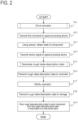
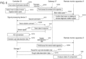
- FIG. 2 is a flowchart of rough diagnosis processing performed by executing the rough diagnosis program 25.
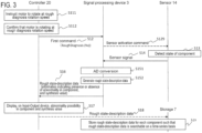
- FIG. 3 is a sequence diagram of the rough diagnosis processing.
- the controller 20 drives the actuator ACT of the machine tool 1 to change the state of the component COM. Specifically, the operator activates the rough diagnosis program via the Input-Output device 17 at the operation start time of the day.
- the controller 20 calls the control program 24 from the rough diagnosis program 25, and transmits an instruction to the motor 15 to cause the motor 15 to rotate at the rough diagnosis rotation speed (step S111 in FIG. 3 ).
- the "input" from the Input-Output device 17 of the machine tool 1 corresponds to an input to activate the machine tool 1.
- the controller 20 By executing the control program 24, the controller 20 obtains the present rotation speed of the motor 15 from the encoder 16. The controller 20 monitors the present rotation speed of the motor 15 until the present rotation speed of the motor 15 becomes the rough diagnosis rotation speed. Then, upon confirming that the present rotation speed of the motor 15 is the rough diagnosis rotation speed (step S112), the controller 20 transmits the first command to the signal processing device 3 (step S12).
- the first command is a command for instructing rough state-description data to be generated based on a signal from the sensor 14.
- the rough state-description data is relevant to an occurrence of an abnormality in the component COM.
- the first command includes an execution command for executing the rough diagnosis script 36, which describes details of processing of generating rough state-description data based on a signal from the sensor 14, the rough state-description data being relevant to an occurrence of an abnormality in the component COM.
- the rough diagnosis script 36 preferably includes the factor identification information 26, the synthesis information 27, and the threshold included in the threshold information 28.
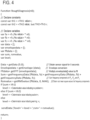
- the rough diagnosis script 36 describes, in a script language, a method of generating the rough state-description data. For example, it is possible to describe a script as illustrated in FIG. 4 .
- the script demands the following processings.
- (i) Obtain a signal from the sensor 14 for 5 seconds, and subject the signal to AD conversion, envelope processing, and FFT to extract the frequency components of the particular frequencies f A , f B , and f C .
- (ii) Obtain the sum of the frequency components.
- (iii) When the sum is in excess of a threshold of TH1 , set the caution value included in the rough state-description data to TRUE.
- TH1 ⁇ TH2 When the sum is in excess of a threshold of TH2 ( TH1 ⁇ TH2 ), set the warning value included in the rough state-description data to TRUE.
- (v) Obtain the root mean square value of all the frequency components.
- (vi) Return the caution value, the warning value, and the execution value.
- FIG. 4 illustrates an example of the rough diagnosis script 36 using JavaScript, which is a representative script language.
- the example illustrated in FIG. 4 is provided for exemplary purposes only, and it is possible to use any other script language or a markup language such as XML.
- RoughDiagnosis function is capable of receiving argument No (the rotation speed of the motor 15).
- the first two lines starting with "const var" declare constants necessary in the program.
- "th1, th2" are respectively substituted with the above-described TH1 and TH2 values read from the threshold information 28.
- fftdata is an array in which frequency spectra obtained by subjecting "envelopdata” to fast Fourier transformation are stored.
- the elements of this array indicate, for example, frequency component values indicated on a frequency basis.
- sum the sum of the f A , f B , and f C frequency components is stored.
- rsmvalue the root mean square value of the frequency components is stored.
- level determination values indicating no problem, caution, and warning are stored.
- “getData” is a function that, during the time between function calling and description in the argument, causes the signal processing device 3 to A/D convert the signal from the sensor 14 to obtain a digital value, and outputs the digital value to variable "data". "data" is, physically, stored in the memory 32. It is to be noted that “getData” is an example function name, that any other function name may be used, and that the argument may be omitted. In a case where the argument is omitted, the signal processing device 3 obtains the signal from the sensor 14 for a time determined by default. Also, in a case where the signal processing device 3 includes a plurality of connection ports connectable to the sensor 14, a port number may be included as the argument for "getData".
- “getEnvelope” is a function that subjects argument "data” to envelope processing to obtain envelope data and outputs the envelope data to the variable "envelopedata”. Envelope processing is processing of taking an absolute value of an oscillatory wave form to detect an envelope curve.
- envelopedata is, physically, stored in the memory 32.
- “getEnvelope” is an example function name and that any other function name may be used.
- “getFFT” is a function that subjects the argument "envelopedata” to fast Fourier transformation to obtain a frequency spectrum and outputs the frequency spectrum to the variable "fftdata”.
- "fftdata” is, physically, stored in the memory 32. It is to be noted that “getFFT” is an example function name and that any other function name may be used. Also, in a case where a frequency component limited to a particular frequency range is output, it is possible to specify, as the argument for "getFFT", at least one of the minimal value and the maximum value of the frequency range.
- “getFrequencyData(A,B)” outputs a frequency component corresponding to a frequency value that serves as an argument B from a frequency spectrum that serves as an argument A. For each of “fa”, “fb”, and “fc”, “getFrequencyData” is called and the return values are added together so that the sum is substituted with the sum of the f A , f B , f C frequency components. It is to be noted that “getFrequencyData” is an example function name and that any other function name may be used. It is also to be noted that the order of the arguments may be reversed and/or the argument data form may be any other form. For example, the argument B may specify the order of certain data in the array fftdata[].
- “getRMSvalue(A, B, C)” calculates, from the frequency spectrum that serves as the argument A, a root mean square value in a frequency range [B, C] specified by arguments B and C.
- a root mean square value is calculated in the range from frequency 0 to MAX, which is the maximum frequency calculable by the signal processing device 3. It is to be noted that the maximum frequency MAX may be specified at any value that is twice or more than twice the frequency necessary to be detected.
- a determination value indicating caution is substituted when "sum” is equal to TH1 or less than TH2.
- a determination value indicating warning is substituted when "sum” is TH2 or more.
- "sendData” is a function that transmits, as rough state-description data, a character string described as an argument.
- the synthesis information 27 may be, for example, information that includes the codes of the script illustrated in FIG. 4 excluding the constant declaration.
- the controller 20 may generate the first command by: reading the factor identification information 26, the synthesis information 27, and the threshold information 28; and adding a constant declaration to the codes stored as the synthesis information 27 based on the factor identification information 26, and the value stored in the threshold information 28.
- the first command may be a binary code, instead of a script.
- the controller 20 may generate a binary code including details of the processing of the above-described script.
- the communication interface 34 of the signal processing device 3 may include a parser for analyzing the binary code of the first command. It is to be noted that in FIG. 4 , the first command may use a function that outputs an integration value of all the frequency components, instead of using the function that outputs a rated value ("getRMSvalue(A, B, C)").
- the first command is an execution command for executing the rough diagnosis script 36 represented by the above-described RoughDiagnosis.
- the first command also includes a rough diagnosis rotation speed as an argument of RoughDiagnosis. It is to be noted, however, that in a case where a rough diagnosis rotation speed is transmitted in advance to the signal processing device 3 as an argument of RoughDiagnosis, the first command may not necessarily include a rough diagnosis rotation speed.
- the signal processing device 3 Upon receipt of the first command, the signal processing device 3 performs the processing described by the script engine 37 in the rough diagnosis script 36. Then, in accordance with the command described in "getData", the signal processing device 3 transmits a sensor activation command to the sensor 14 (step S129).
- the sensor 14 Upon receipt of the sensor activation command, the sensor 14 detects a state of the component COM (step S13). The sensor 14 transmits, to the signal processing device 3, a signal (sensor signal) indicating the state detected by the sensor 14 (step S14). It is to be noted that step S129 may be omitted in a case where the sensor 14 continually outputs a sensor signal to the signal processing device 3, irrespective of the presence and absence of a sensor activation command.
- the signal processing device 3 Upon receipt of the sensor signal, the signal processing device 3 generates, based on the signal, rough state-description data, which is relevant to an occurrence of an abnormality in the component COM (step S15). Specifically, the signal processing device 3 converts the sensor signal into a digital value (step S151).
- the signal processing device 3 generates rough state-description data based on the signal (step S152). Specifically, in accordance with commands defined by "getFFT” and “getFrequencyData” illustrated in FIG. 4 , the signal processing device 3 extracts, from the signal, a plurality of factors relevant to an abnormality in the component COM. That is, the signal processing device 3 is configured to extract the plurality of factors from the signal.
- the signal processing device 3 is configured to calculate a synthesis value obtained by synthesizing at least two factors of the plurality of factors. Based on the logical formula "if (sum ⁇ th1) ... else if (sum ⁇ th2) ... else " illustrated in FIG. 4 , the signal processing device 3 determines (caution, warning) whether an abnormality is occurring in the components COM. That is, based on the above-described plurality of factors and threshold, the signal processing device 3 determines whether the abnormality is occurring in the components COM.
- the signal processing device 3 is configured to determine whether the abnormality is occurring in the components COM. Also, in accordance with an operation described by the argument of "sendData", the signal processing device 3 generates the rough state-description data based on the signal.
- This argument includes "sum”, that is, the sum of the f A , f B , and f C frequency components. That is, the rough state-description data includes a synthesis value configured by at least two factors of the plurality of factors relevant to the abnormality in the component COM.
- the rough state-description data includes "level”, that is, information indicating whether the abnormality is occurring in the component COM.
- the signal processing device 3 transmits the generated rough state-description data to the controller 20, which controls an operation of the actuator ACT.
- the controller 20 may store the received rough state-description data in relation to the time of receipt.
- the controller 20, at step S 17, controls the Input-Output device 17 to display the synthesis value and information indicating whether the abnormality is occurring in the component COM. That is, based on the rough state-description data transmitted to the controller 20, the controller 20 notifies, via the Input-Output device 17, the operator of information indicating whether the abnormality is occurring in the component COM. In this notification, the controller 20 notifies the operator of the present rough state-description data.
- the controller 20 may control the Input-Output device 17 to display time-series changes in the degree of the abnormality in the component COM and time-series changes in the synthesis value.
- step S 17 in a case where no abnormality (warning) is notified, the controller 20 permits the machining program to be executed. Then, the machine tool 1 is permitted to perform machining. The subsequent machining is performed by the operator's manipulation of the Input-Output device 17. For this reason, outputting the result of the rough diagnosis on the Input-Output device 17 is advantageous for smoothly performing the subsequent machining.
- the controller 20 in a case where an abnormality (warning) is notified, the controller 20 notifies, via the Input-Output device 17, the abnormality and a measure that the operator should take. For example, a detailed diagnosis is recommended to the operator. It is to be noted that at step S 18, the controller 20 performs an optional processing.
- the controller 20 transmits the received rough state-description data to the storage 7, which is accessible by the remote monitor apparatus 9 via the communication network 53.
- the storage 7 stores sets of the rough state-description data for each of the components COM such that the sets of the rough state-description data are searchable on a time-series basis.
- the storage 7 may manage the rough state-description data based on the address of the controller 20 transmitted such that sets of the rough state-description data are searchable for each of components COM.
- the rough state-description data includes information on the components COM and that based on the information, the storage 7 may manage the rough state-description data for each of the components COM.
- Steps S18 and S19 are optional processings and may be omitted.
- the detailed diagnosis is mainly performed in the following three cases (1) to (3).
- the operator facing the Input-Output device 17 after step S17 illustrated in FIG. 4 makes a phone call to or otherwise contacts a person in charge of operating the remote monitor apparatus 9.
- the result of the rough diagnosis is output on the Input-Output device 17. This is advantageous for smoothly taking a measure.
- an accident is likely to occur during machining work with the operator facing the Input-Output device 17.
- the operator being aware of the accident makes a phone call to or otherwise contacts the person in charge of operating the remote monitor apparatus 9.
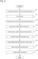
- detailed diagnosis processing is performed, which is illustrated using a flowchart in FIG. 5 .
- a sequence diagram of the detailed diagnosis processing performed after the contact is illustrated in FIG. 6 .
- processings common to the rough diagnosis method and the detailed diagnosis method are designated with like reference numerals and will not be elaborated upon here.
- a permission instruction is input via the Input-Output device 17 to permit detailed state-description data to be output to the remote monitor apparatus 9.
- the gateway 57 is performing control of prohibiting access from the remote monitor apparatus 9.
- the controller 20 inputs a permission instruction to the gateway 57.
- the gateway 57 permits access from the remote monitor apparatus 9 until one of the following events (1) to (4) occurs.
- step S20 the operator activates the security program 29 via the Input-Output device 17 at step S201 of FIG. 6 to input the output of the permission instruction.
- the security program 29 performs processing of transmitting the permission instruction to the gateway 57. That is, the controller 20 transmits the permission instruction to the gateway 57.
- the gateway 57 permits access from the remote monitor apparatus 9 (step S203) until any one of the events (1) to (4) occurs (step S204).
- the controller 20 drives the actuator ACT of the machine tool 1 to change the state of the component COM.
- the operator calls the control program 24 to transmit an instruction to the motor 15 to control the motor 15 to rotate at the rotation speed notified from the person in charge or the rotation speed notified at step S17 illustrated in FIGs. 3 and 4 (step S211).
- this rotation speed will be referred to as remote diagnosis rotation speed.
- the controller 20 obtains a motor rotation speed at this moment from the encoder 16 and transmits the motor rotation speed to the remote monitor apparatus 9 (step S212).
- the remote monitor apparatus 9 by referring to the motor rotation speed transmitted from the controller 20, checks whether the motor 15 is rotating at the remote rotation speed (step S213).
- the the remote monitor apparatus 9 transmits a second command to the signal processing device 3.
- the second command instructs detailed state-description data to be generated based on the signal.
- the detailed state-description data is for identifying the abnormal part in the component COM and is more informative than the rough state-description data (step S22).
- the signal processing device 3 receives the second command for the time during which the permission instruction permits the detailed state-description data to be transmitted to the remote monitor apparatus 9.
- the signal processing device 3 is configured to receive the second command for the time during which the permission instruction permits the detailed state-description data to be transmitted to the remote monitor apparatus 9.
- the following (i) to (iv) are examples of the second command.
- the commands (i) to (iv) can also be implemented using the script described above by referring to FIG. 4 .
- the second command can be implemented by a script that reads the output value of the "getData” function illustrated in FIG. 4 into the "sendData” function.
- the second command can be implemented by a script that reads the output value of "getFFT” illustrated in FIG. 4 into the "sendData” function.
- the second command can be implemented by a script that reads the output value of the "getRMScalue” function illustrated in FIG. 4 into the "sendData” function.
- the second command can be implemented by a script that reads the output value of any one of the functions "getFrequencyData (fft, fa)", “getFrequencyData (fft, fb)", and “getFrequencyData (fft, fc)" illustrated in FIG. 4 into the "sendData" function. It is to be noted that these scripts are examples of the second command and that the second command may be implemented by any other method such as a binary code method. It is also to be noted that the second command may include a command other than the commands (i) to (iv).
- step S229 may be omitted in a case where the sensor 14 continually outputs a sensor signal to the signal processing device 3, irrespective of the presence and absence of a sensor activation command.
- step S14 the signal processing device 3 generates rough state-description data based on the sensor signal.
- the rough state-description data is relevant to an occurrence of an abnormality in the component COM (step S25).
- the signal processing device 3 performs an AD conversion (step S151) and generates detailed state-description data based on the signal (step S252). Specifically, upon receipt of the second command, the signal processing device 3 generates detailed state-description data based on the signal from the sensor 14.
- the detailed state-description data is for identifying an abnormal part in the component COM and is more informative than the rough state-description data.
- the signal processing device 3 in a case where the second command is a command such as (i), the signal processing device 3 generates, as the detailed state-description data, digital data obtained by digitizing the signal from the sensor 14. In a case where the second command is a command such as (ii), the signal processing device 3 generates the frequency spectrum as the detailed state-description data. In a case where the second command is a command such as (iii), the signal processing device 3 generates the root mean square value as the detailed state-description data. In a case where the second command is a command such as (iv), the signal processing device 3 generates, as the detailed state-description data, the frequency components of any one of the particular frequencies f A , f B , and f C .
- the detailed state-description data includes a plurality of factors relevant to an abnormality in the component COM (for example, frequency components of any one of the particular frequencies f A , f B , and f C ) such that the plurality of factors are identifiable.
- the signal processing device 3 transmits the generated detailed state-description data to the remote monitor apparatus 9. More specifically, while the detailed state-description data is permitted by the permission instruction to be transmitted to the remote monitor apparatus 9, the signal processing device 3 transmits the generated detailed state-description data to the remote monitor apparatus 9. While the detailed state-description data is permitted by the permission instruction to be transmitted to the remote monitor apparatus 9, the signal processing device 3 is configured to transmit the generated detailed state-description data to the remote monitor apparatus 9.
- the remote monitor apparatus 9 analyzes detailed state-description data, the remote monitor apparatus 9 obtains the rough state-description data from the storage 7. Specifically, at step S271, the remote monitor apparatus 9 transmits a request message requesting the rough state-description data.
- This request message at least includes information (such as ID) for identifying the component COM and information specifying the period of time of the rough state-description data, which is the data to be transmitted.
- the storage 7 transmits the rough state-description data specified by the request message to the remote monitor apparatus 9. It is to be noted that step S27 (steps S 271 and S 272) may be omitted.
- the remote monitor apparatus 9 analyzes the state of the component COM using the received detailed state-description data and rough state-description data.
- the diagnosis system 100, and the diagnosis method for the machine tool 1 sensor signal processing for abnormality diagnosis purposes is performed separately at the signal processing device 3, which is different from the controller 20. This ensures that rough abnormality diagnosis processing in the machine tool 1 and detailed abnormality diagnosis processing performed for the machine tool by a remote diagnosis device are both realized while preventing the load on the controller 20 from being significantly heavy. Also, by employing a centralized configuration in which input operations for the operations of the machine tool 1 and notifications of rough abnormality diagnosis results are both performed in the machine tool 1, operator-friendliness of rough abnormality diagnosis improves.
- the rough diagnosis rotation speed, the factor identification information 26, the threshold information 28, and the rough diagnosis script 36 may be replaceable with other data from the remote monitor apparatus 9.
- the synthesis information 27 may be replaceable by the remote monitor apparatus 9 with a template of a script describing other synthesis information 27 (in the script illustrated in FIG. 4 , information that includes codes excluding the factor identification information 26 and the threshold information 28).
- the factor identification information 26, the synthesis information 27, and the threshold information 28 may be combined into one piece of information. As an example of such one piece of information, it is possible to store the rough diagnosis script 36 itself in the memory 22.
- the rough diagnosis program 25, rough diagnosis rotation speed, the factor identification information 26, the synthesis information 27, and the threshold information 28 may be stored in the memory 22 as one rough diagnosis program 25.
- the rough diagnosis script 36 may be transmitted from other than the controller 20 to the signal processing device 3 and installed therein.
- the component COM is the bearing 13, which supports the spindle 11.
- the component COM may be any other part.
- the components COM may also be a greater configuration unit.
- the component COM may be the spindle 11.
- the network 5 may not necessarily be a wired network but may be a wireless network.
- the communication network 53 may be replaced with a dedicated line or a telephone line to the manufacturer.
- a predetermined value is used as the rough diagnosis rotation speed. Another possible example is that the operator inputs the rough diagnosis rotation speed from the Input-Output device 17, and the rough diagnosis program 25 performs processing of generating the first command.
- the frequency components of the particular frequencies f A , f B , and f C are not factors susceptible to an abnormal engagement between the plurality of parts.
- the frequency components of the particular frequencies may include factors susceptible to an abnormal engagement between the plurality of parts.
- An example is a case where a holder has a defect while the rolling element 13B of the bearing 13 is being held in the holder (in a case where the rolling element 13B is making an orbital rotation about the rotation axis of the motor 15 while being displaced from the intended position of the rolling element 13B).
- the frequency component of the following frequency f D is susceptible to the defect.
- the plurality of factors relevant to an abnormality in the component COM may include the frequency component of the frequency f D as a factor susceptible to an abnormal engagement between the plurality of parts.
- f D (No/120) • (1- d • cos ⁇ / D ) (4)
- At least one or all of the functions of the control program 24, the rough diagnosis program 25, and the security program 29 may be implemented by a dedicated processor and/or an integrated circuit.
- the control program 24, the rough diagnosis program 25, and the security program 29 may not necessarily be stored in the memory 22, which is incorporated in to the controller 20; these programs may be recorded in a storage medium removable from the controller 20 and readable into the controller 20. Examples of the storage medium include: a disc such as a floppy disc (diskette), an optical disc, a CD-ROM, and a magnetic disc; an SD card; a USB memory; and an external hard disc.
- the controller 20 is an example of the computer.
- a component suffixed with a term such as "member”, “portion”, “part”, “element”, “body”, and “structure” is intended to mean that there is a single such component or a plurality of such components.
- ordinal terms such as “first” and “second” are merely used for distinguishing purposes and there is no other intention (such as to connote a particular order) in using ordinal terms.
- first element does not connote the existence of “second element”; otherwise, the mere use of “second element” does not connote the existence of "first element”.
- approximating language such as “approximately”, “about”, and “substantially” may be applied to modify any quantitative representation that could permissibly vary without a significant change in the final result obtained. All of the quantitative representations recited in the present application shall be construed to be modified by approximating language such as “approximately”, “about”, and “substantially”.
Landscapes
- Engineering & Computer Science (AREA)
- Physics & Mathematics (AREA)
- General Physics & Mathematics (AREA)
- Automation & Control Theory (AREA)
- Human Computer Interaction (AREA)
- Manufacturing & Machinery (AREA)
- Mechanical Engineering (AREA)
- Testing And Monitoring For Control Systems (AREA)
- Numerical Control (AREA)
Claims (14)
- Système de diagnostic (100) pour une machine-outil (1), comprenant :un composant (13) dont l'état est variable en fonction d'une opération d'un actionneur (15) de la machine-outil (1) ;un capteur (14) conçu pour détecter l'état du composant (13) ;un contrôleur (20) conçu pour contrôler l'opération de l'actionneur (15) ;un dispositif d'entrée-sortie (17) conçu pour recevoir une instruction pour que le contrôleur (20) contrôle l'actionneur (15) pour conduire l'opération, et conçu pour signaler un statut d'opération de l'actionneur (15) ;un dispositif de traitement du signal (3) conçu pour traiter un signal provenant du capteur (14) ;un appareil de surveillance à distance (9) conçu pour analyser l'état du composant (13) ;un réseau de communication (53) connectant l'appareil de surveillance à distance (9) et le dispositif de traitement du signal (3) l'un à l'autre ; etune passerelle (57) disposée entre l'appareil de surveillance à distance (9) et le dispositif de traitement du signal (3) sur le réseau de communication (53) ;dans lequel le dispositif de traitement du signal (3) est conçu pour :en fonction du signal, générer des données grossières de description d'état relatives à l'apparition d'une anomalie dans le composant (13), les données grossières de description d'état comprenant des informations indiquant qu'une anomalie est apparue dans le composant (13) ;transmettre les données grossières de description d'état générées au contrôleur (20) ;en fonction du signal, générer des données détaillées de description d'état qui servent à identifier une pièce anormale dans le composant (13) et qui comprennent des informations supplémentaires par rapport à celles des données grossières de description d'état ; ettransmettre les données détaillées de description d'état générées à l'appareil de surveillance à distance (9) qui est conçu pour analyser l'état du composant (13), etdans lequel, en fonction des données grossières de description d'état transmises au contrôleur (20), le dispositif d'entrée-sortie (17) est conçu pour signaler à un opérateur que l'anomalie est apparue dans le composant (13),dans lequel l'appareil de surveillance à distance (9) est conçu pour transmettre une deuxième commande au dispositif de traitement du signal (3) pour contrôler le dispositif de traitement du signal (3) pour générer les données détaillées de description d'état en fonction du signal,dans lequel la deuxième commande comprend des informations spécifiant au moins une donnée qui est associée à l'anomalie dans le composant (13) et qui peut être générée à partir du signal, etdans lequel le dispositif de traitement du signal (3) est conçu pour :générer, en fonction du signal, l'au moins une donnée spécifiée par la deuxième commande ;générer les données détaillées de description d'état comprenant l'au moins une donnée de telle sorte que l'au moins une donnée soit identifiable ; ettransmettre les données détaillées de description d'état générées à l'appareil de surveillance à distance (9).
- Système de diagnostic (100) selon la revendication 1, dans lequel les informations spécifiant l'au moins une donnée comprennent sélectivementdes informations spécifiant un spectre de fréquences obtenu par réalisation d'un traitement d'enveloppe et d'une transformée de Fourier rapide sur des données numériques obtenues par numérisation du signal provenant du capteur (14),des informations spécifiant une valeur moyenne quadratique de toutes les composantes de fréquence obtenues à partir du spectre de fréquences, etdes informations spécifiant une fréquence particulière obtenue à partir du spectre de fréquences.
- Système de diagnostic (100) selon la revendication 1,dans lequel le contrôleur (20) est conçu pour transmettre une première commande au dispositif de traitement du signal (3) pour contrôler le dispositif de traitement du signal (3) pour générer les données grossières de description d'état en fonction du signal, etdans lequel le dispositif de traitement du signal (3) est conçu pour générer les données grossières de description d'état lors de la réception de la première commande, et conçu pour transmettre les données grossières de description d'état générées au contrôleur (20).
- Système de diagnostic (100) selon la revendication 1, comprenant en outre une ligne de communication (51) connectant le contrôleur (20) et le dispositif de traitement du signal (3) l'un à l'autre,dans lequel la passerelle (57) est disposée entre le dispositif de traitement du signal (3) et l'appareil de surveillance à distance (9),dans lequel la première commande et les données grossières de description d'état sont transmises par le biais de la ligne de communication (51),dans lequel la deuxième commande et les données détaillées de description d'état sont transmises par le biais du réseau de communication (53), etdans lequel la capacité de communication de la ligne de communication (51) est inférieure à la capacité de communication du réseau de communication (53).
- Système de diagnostic (100) selon l'une quelconque des revendications 3 et 4, dans lequel la première commande comprend au moins un élément parmi :un code de programme destiné à générer les données grossières de description d'état en fonction du signal ; etune commande d'exécution pour exécuter le code de programme transmis depuis le contrôleur (20) au dispositif de traitement du signal (3) et stocké dans le dispositif de traitement du signal (3).
- Système de diagnostic (100) selon la revendication 5,dans lequel le code de programme comprenddes informations d'identification de composantes (26) destinées à identifier une pluralité de composantes de fréquence du signal provenant du capteur (14), la pluralité de composantes de fréquence se rapportant à l'anomalie dans le composant (13), etdes informations de synthèse (27) spécifiant un procédé de synthèse consistant à synthétiser au moins deux composantes de fréquence de la pluralité de composantes de fréquence sont synthétisées l'une avec l'autre, etdans lequel, lors de l'exécution du code de programme, le dispositif de traitement du signal (3) est conçu pour extraire la pluralité de composantes de fréquence du signal, et conçu pour synthétiser les au moins deux composantes de fréquence l'une avec l'autre selon le procédé de synthèse pour obtenir une valeur de synthèse.
- Système de diagnostic (100) selon la revendication 6, dans lequel les données grossières de description d'état comprennent la valeur de synthèse.
- Système de diagnostic (100) selon l'une quelconque des revendications 6 et 7,dans lequel le code de programme comprend un seuil destiné à déterminer l'anomalie dans le composant (13),dans lequel, lors de l'exécution du code de programme, le dispositif de traitement du signal (3) est conçu pour, en fonction de la pluralité de composantes de fréquence et du seuil, déterminer si l'anomalie est apparue dans le composant (13), etdans lequel les données grossières de description d'état comprennent des informations indiquant si l'anomalie est apparue dans le composant (13).
- Système de diagnostic (100) selon l'une quelconque des revendications 6 à 8,dans lequel le composant (13) comprend une pluralité de pièces,dans lequel l'anomalie comprend une pluralité de défauts incluant un endommagement de la pluralité de pièces et une mise en prise anormale entre la pluralité de pièces, etdans lequel chacun de la pluralité de défauts est indiqué par au moins une de la pluralité de composantes de fréquence.
- Système de diagnostic (100) selon la revendication 9dans lequel la pluralité de pièces comprend une bague interne (13A), une bague externe (13C) et un élément roulant (13B) d'un roulement disposé dans le composant (13),dans lequel le capteur (14) comprend un capteur de vibrations conçu pour détecter une vibration du roulement,dans lequel la pluralité de composantes de fréquence comprendune composante qui correspond à une première fréquence (fA) du signal provenant du capteur de vibrations et qui est sensible à un endommagement de la bague interne (13A),une composante qui correspond à une deuxième fréquence (fC) du signal provenant du capteur de vibrations et qui est sensible à un endommagement de la bague externe (13C), etune composante qui correspond à une troisième fréquence (fB) du signal provenant du capteur de vibrations et qui est sensible à un endommagement de l'élément roulant (13B), etdans lequel les informations d'identification de composantes comprennent des informations identifiant la première fréquence (fA), la deuxième fréquence (fC) et la troisième fréquence (fB).
- Système de diagnostic (100) selon l'une quelconque des revendications 1 à 4,dans lequel une instruction d'autorisation est entrée dans la machine-outil (1) par le biais du dispositif d'entrée-sortie (17) pour autoriser la délivrance des données détaillées de description d'état à l'appareil de surveillance à distance (9), etdans lequel, pendant que la transmission des données détaillées de description d'état à l'appareil de surveillance à distance (9) est autorisée par l'instruction d'autorisation, le dispositif de traitement du signal (3) est conçu pour recevoir la deuxième commande et transmettre les données détaillées de description d'état à l'appareil de surveillance à distance (9).
- Système de diagnostic (100) selon l'une quelconque des revendications 1 à 11, comprenant en outre un dispositif de stockage (7) accessible à l'appareil de surveillance à distance (9) par le biais du réseau de communication (53),dans lequel le contrôleur (20) est conçu pour transmettre les données grossières de description d'état au dispositif de stockage (7),dans lequel le dispositif de stockage (7) est conçu pour stocker des ensembles des données grossières de description d'état pour chacun d'une pluralité des composants (13) de telle sorte que les ensembles des données grossières de description d'état sont consultables sous la forme d'une série chronologique, etdans lequel l'appareil de surveillance à distance (9) est conçu pour obtenir les données grossières de description d'état depuis le dispositif de stockage (7) quand l'appareil de surveillance à distance (9) analyse les données détaillées de description d'état.
- Procédé de diagnostic d'une machine-outil (1), le procédé comprenant :l'entraînement d'un actionneur (15) de la machine-outil (1) en fonction d'une entrée par le biais d'un dispositif d'entrée-sortie (17) de la machine-outil (1) pour changer un état d'un composant (13) de la machine-outil (1) ;la détection de l'état du composant (13) par un capteur (14) ;la transmission, à un dispositif de traitement du signal (3) de la machine-outil (1), d'un signal indiquant l'état détecté par le capteur (14) ;la génération, en fonction du signal et au moyen du dispositif de traitement du signal (3), de données grossières de description d'état relatives à l'apparition d'une anomalie dans le composant (13) par le dispositif de traitement du signal (3), les données grossières de description d'état comprenant des informations indiquant qu'une anomalie est apparue dans le composant (13) ;la transmission des données grossières de description d'état générées à un contrôleur (20) qui est conçu pour contrôler une opération de l'actionneur (15) ;la génération, en fonction du signal et au moyen du dispositif de traitement du signal (3), de données détaillées de description d'état qui servent à identifier une pièce anormale dans le composant (13) et qui comprennent des informations supplémentaires par rapport à celles des données grossières de description d'état en fonction du signal par le dispositif de traitement du signal (3) ;la transmission des données détaillées de description d'état générées à un appareil de surveillance à distance (9) qui est conçu pour analyser l'état du composant (13) ; etle signalement, par le biais du dispositif d'entrée-sortie (17) et en fonction des données grossières de description d'état transmises au contrôleur (20), à un opérateur que l'anomalie est apparue dans le composant (13),la transmission, au moyen de l'appareil de surveillance à distance (9), d'une deuxième commande au dispositif de traitement du signal (3) pour contrôler le dispositif de traitement du signal (3) pour générer les données détaillées de description d'état en fonction du signal, la deuxième commande comprenant des informations spécifiant au moins une donnée qui est associée à l'anomalie dans le composant (13) et qui peut être générée à partir du signal ; etla génération, au moyen du dispositif de traitement du signal (3), en fonction du signal, de l'au moins une donnée spécifiée par la deuxième commande,la génération, au moyen du dispositif de traitement du signal (3), des données détaillées de description d'état comprenant l'au moins une donnée de telle sorte que l'au moins une donnée soit identifiable, etla transmission, au moyen du dispositif de traitement du signal (3), des données détaillées de description d'état générées à l'appareil de surveillance à distance (9).
- Procédé selon la revendication 13, dans lequel les informations spécifiant l'au moins une donnée comprennent sélectivementdes informations spécifiant un spectre de fréquences obtenu par réalisation d'un traitement d'enveloppe et d'une transformée de Fourier rapide sur des données numériques obtenues par numérisation du signal provenant du capteur (14),des informations spécifiant une valeur moyenne quadratique de toutes les composantes de fréquence obtenues à partir du spectre de fréquences, etdes informations spécifiant une fréquence particulière obtenue à partir du spectre de fréquences.
Applications Claiming Priority (1)
| Application Number | Priority Date | Filing Date | Title |
|---|---|---|---|
| PCT/JP2021/014008 WO2022208803A1 (fr) | 2021-03-31 | 2021-03-31 | Machine-outil, système de diagnostic pour machine-outil et procédé de diagnostic pour machine-outil |
Publications (3)
| Publication Number | Publication Date |
|---|---|
| EP4283418A1 EP4283418A1 (fr) | 2023-11-29 |
| EP4283418A4 EP4283418A4 (fr) | 2024-03-20 |
| EP4283418B1 true EP4283418B1 (fr) | 2024-12-25 |
Family
ID=82492226
Family Applications (1)
| Application Number | Title | Priority Date | Filing Date |
|---|---|---|---|
| EP21934968.5A Active EP4283418B1 (fr) | 2021-03-31 | 2021-03-31 | Système de diagnostic pour machine-outil et procédé de diagnostic pour machine-outil |
Country Status (5)
| Country | Link |
|---|---|
| US (1) | US20240017367A1 (fr) |
| EP (1) | EP4283418B1 (fr) |
| JP (1) | JP7104858B1 (fr) |
| CN (1) | CN116888545A (fr) |
| WO (1) | WO2022208803A1 (fr) |
Families Citing this family (2)
| Publication number | Priority date | Publication date | Assignee | Title |
|---|---|---|---|---|
| CN119325557A (zh) | 2023-05-15 | 2025-01-17 | 日本精工株式会社 | 机械设备监视系统和机械设备监视方法 |
| CN120962437B (zh) * | 2025-10-21 | 2026-03-24 | 南通艺能达精密制造科技有限公司 | 一种基于软件系统的绿色数控加工方法 |
Family Cites Families (15)
| Publication number | Priority date | Publication date | Assignee | Title |
|---|---|---|---|---|
| JPS63297813A (ja) * | 1987-05-28 | 1988-12-05 | Fuji Electric Co Ltd | ころがり軸受異常診断装置 |
| JPH0695723A (ja) * | 1991-02-19 | 1994-04-08 | Enshu Ltd | 工作機械のリモート診断方法とその処置 |
| JPH10222220A (ja) * | 1997-02-12 | 1998-08-21 | Mitsubishi Electric Corp | リモート診断システム |
| JP3543147B2 (ja) * | 2001-07-10 | 2004-07-14 | ヤマザキマザック株式会社 | 工作機械の異常管理装置 |
| JP2004192326A (ja) * | 2002-12-11 | 2004-07-08 | Hibiya Eng Ltd | リモートライフサイクルマネジメントサポートシステム |
| JP2004265009A (ja) * | 2003-02-28 | 2004-09-24 | Mitsubishi Electric Corp | 診断システム |
| JP4337084B2 (ja) * | 2003-03-28 | 2009-09-30 | マツダ株式会社 | 遠隔故障診断システム |
| JP2016033705A (ja) * | 2014-07-31 | 2016-03-10 | ブラザー工業株式会社 | 数値制御装置、制御方法、記憶媒体 |
| JP6714806B2 (ja) * | 2015-08-06 | 2020-07-01 | 日本精工株式会社 | 状態監視装置及び状態監視方法 |
| JP2017219469A (ja) * | 2016-06-09 | 2017-12-14 | 日本精工株式会社 | 状態監視装置及び状態監視方法 |
| JP6550417B2 (ja) * | 2017-03-21 | 2019-07-24 | 株式会社日産アーク | 解析支援システム |
| JP2018179735A (ja) * | 2017-04-12 | 2018-11-15 | 日本精工株式会社 | 回転部品の異常診断方法及び異常診断装置 |
| JP6998781B2 (ja) * | 2018-02-05 | 2022-02-10 | 住友重機械工業株式会社 | 故障診断システム |
| JP6507297B1 (ja) * | 2018-09-07 | 2019-04-24 | オークマ株式会社 | 転がり軸受の異常診断方法及び異常診断装置、異常診断プログラム |
| JP6805314B1 (ja) * | 2019-10-15 | 2020-12-23 | 株式会社川本製作所 | 軸受異常検出装置 |
-
2021
- 2021-03-31 CN CN202180093899.4A patent/CN116888545A/zh active Pending
- 2021-03-31 WO PCT/JP2021/014008 patent/WO2022208803A1/fr not_active Ceased
- 2021-03-31 JP JP2021554372A patent/JP7104858B1/ja active Active
- 2021-03-31 EP EP21934968.5A patent/EP4283418B1/fr active Active
-
2023
- 2023-09-28 US US18/477,487 patent/US20240017367A1/en active Pending
Also Published As
| Publication number | Publication date |
|---|---|
| EP4283418A4 (fr) | 2024-03-20 |
| JP7104858B1 (ja) | 2022-07-21 |
| US20240017367A1 (en) | 2024-01-18 |
| CN116888545A (zh) | 2023-10-13 |
| WO2022208803A1 (fr) | 2022-10-06 |
| JPWO2022208803A1 (fr) | 2022-10-06 |
| EP4283418A1 (fr) | 2023-11-29 |
Similar Documents
| Publication | Publication Date | Title |
|---|---|---|
| CN114184955B (zh) | 电机故障检测方法、系统及存储介质 | |
| US20240017367A1 (en) | Machine tool, diagnosis system for machine tool, and method of diagnosing machine tool | |
| CN100487475C (zh) | 用于检测感应电机中电动机内部故障的方法和装置 | |
| KR101482509B1 (ko) | 베어링 결함 진단 시스템 및 그 진단 방법 | |
| JP6542735B2 (ja) | 管理システム、主軸故障検出方法及びコンピュータプログラム | |
| EP2950177A1 (fr) | Surveillance d'état d'un équipement | |
| CN115033609B (zh) | 一种起升机构非稳态负载下振动监测分析方法、装置、设备及存储介质 | |
| CA2712158A1 (fr) | Dispositif de diagnostic et de pronostic de defaut d'aerogenerateur, et methode | |
| JP2018153081A (ja) | 電気的シグネチャ解析に基づく機械の監視と診断のための自律的手順 | |
| WO2018158910A1 (fr) | Dispositif et procédé de diagnostic | |
| CN107695790A (zh) | 伺服控制装置、主轴故障检测方法以及计算机可读介质 | |
| US20240355154A1 (en) | Health diagnosis method and system for motor bearings of electric vehicle | |
| EP3819608A1 (fr) | Détection d'anomalies de rotor en déterminant les tendances de vibration pendant un fonctionnement à régime transitoire | |
| JP7528035B2 (ja) | 機械設備の振動監視装置 | |
| CN114253183A (zh) | 压缩机监控数据的处理方法以及装置 | |
| JPWO2004068078A1 (ja) | 状態判定方法と状態予測方法及び装置 | |
| CN115389190A (zh) | 一种设备运行状态的诊断系统 | |
| KR101490471B1 (ko) | 신호 계측 및 진단 시스템과 그 방법 | |
| CN111856268A (zh) | 基于谐波法的电动机和发电机故障诊断系统 | |
| CN110543141B (zh) | 诊断装置、诊断方法以及诊断程序 | |
| CN113359026A (zh) | 电机参数诊断装置及系统 | |
| JP7552229B2 (ja) | 異常検知システム、データ処理装置、異常検知装置、及び異常検知方法 | |
| KR101482511B1 (ko) | 위상 지연과 데이터 분포 형상지수를 이용한 베어링 결함 진단 시스템 및 그 진단 방법 | |
| KR20040036980A (ko) | 기계 상태 감시 시스템 및 그 서버 | |
| CN116040483A (zh) | 起重机回转支承工作状态评估方法、系统及存储介质 |
Legal Events
| Date | Code | Title | Description |
|---|---|---|---|
| STAA | Information on the status of an ep patent application or granted ep patent |
Free format text: STATUS: THE INTERNATIONAL PUBLICATION HAS BEEN MADE |
|
| PUAI | Public reference made under article 153(3) epc to a published international application that has entered the european phase |
Free format text: ORIGINAL CODE: 0009012 |
|
| STAA | Information on the status of an ep patent application or granted ep patent |
Free format text: STATUS: REQUEST FOR EXAMINATION WAS MADE |
|
| 17P | Request for examination filed |
Effective date: 20230825 |
|
| AK | Designated contracting states |
Kind code of ref document: A1 Designated state(s): AL AT BE BG CH CY CZ DE DK EE ES FI FR GB GR HR HU IE IS IT LI LT LU LV MC MK MT NL NO PL PT RO RS SE SI SK SM TR |
|
| STAA | Information on the status of an ep patent application or granted ep patent |
Free format text: STATUS: EXAMINATION IS IN PROGRESS |
|
| A4 | Supplementary search report drawn up and despatched |
Effective date: 20240216 |
|
| RIC1 | Information provided on ipc code assigned before grant |
Ipc: G05B 19/4063 20060101ALI20240212BHEP Ipc: G05B 19/18 20060101AFI20240212BHEP |
|
| 17Q | First examination report despatched |
Effective date: 20240228 |
|
| DAV | Request for validation of the european patent (deleted) | ||
| DAX | Request for extension of the european patent (deleted) | ||
| GRAP | Despatch of communication of intention to grant a patent |
Free format text: ORIGINAL CODE: EPIDOSNIGR1 |
|
| STAA | Information on the status of an ep patent application or granted ep patent |
Free format text: STATUS: GRANT OF PATENT IS INTENDED |
|
| RIC1 | Information provided on ipc code assigned before grant |
Ipc: G05B 19/4063 20060101ALI20240722BHEP Ipc: G05B 19/18 20060101AFI20240722BHEP |
|
| INTG | Intention to grant announced |
Effective date: 20240805 |
|
| GRAS | Grant fee paid |
Free format text: ORIGINAL CODE: EPIDOSNIGR3 |
|
| GRAA | (expected) grant |
Free format text: ORIGINAL CODE: 0009210 |
|
| STAA | Information on the status of an ep patent application or granted ep patent |
Free format text: STATUS: THE PATENT HAS BEEN GRANTED |
|
| AK | Designated contracting states |
Kind code of ref document: B1 Designated state(s): AL AT BE BG CH CY CZ DE DK EE ES FI FR GB GR HR HU IE IS IT LI LT LU LV MC MK MT NL NO PL PT RO RS SE SI SK SM TR |
|
| REG | Reference to a national code |
Ref country code: GB Ref legal event code: FG4D |
|
| REG | Reference to a national code |
Ref country code: CH Ref legal event code: EP |
|
| REG | Reference to a national code |
Ref country code: DE Ref legal event code: R096 Ref document number: 602021024060 Country of ref document: DE |
|
| REG | Reference to a national code |
Ref country code: IE Ref legal event code: FG4D |
|
| REG | Reference to a national code |
Ref country code: LT Ref legal event code: MG9D |
|
| PG25 | Lapsed in a contracting state [announced via postgrant information from national office to epo] |
Ref country code: HR Free format text: LAPSE BECAUSE OF FAILURE TO SUBMIT A TRANSLATION OF THE DESCRIPTION OR TO PAY THE FEE WITHIN THE PRESCRIBED TIME-LIMIT Effective date: 20241225 |
|
| PG25 | Lapsed in a contracting state [announced via postgrant information from national office to epo] |
Ref country code: FI Free format text: LAPSE BECAUSE OF FAILURE TO SUBMIT A TRANSLATION OF THE DESCRIPTION OR TO PAY THE FEE WITHIN THE PRESCRIBED TIME-LIMIT Effective date: 20241225 |
|
| PG25 | Lapsed in a contracting state [announced via postgrant information from national office to epo] |
Ref country code: BG Free format text: LAPSE BECAUSE OF FAILURE TO SUBMIT A TRANSLATION OF THE DESCRIPTION OR TO PAY THE FEE WITHIN THE PRESCRIBED TIME-LIMIT Effective date: 20241225 |
|
| PG25 | Lapsed in a contracting state [announced via postgrant information from national office to epo] |
Ref country code: NO Free format text: LAPSE BECAUSE OF FAILURE TO SUBMIT A TRANSLATION OF THE DESCRIPTION OR TO PAY THE FEE WITHIN THE PRESCRIBED TIME-LIMIT Effective date: 20250325 |
|
| PG25 | Lapsed in a contracting state [announced via postgrant information from national office to epo] |
Ref country code: GR Free format text: LAPSE BECAUSE OF FAILURE TO SUBMIT A TRANSLATION OF THE DESCRIPTION OR TO PAY THE FEE WITHIN THE PRESCRIBED TIME-LIMIT Effective date: 20250326 Ref country code: LV Free format text: LAPSE BECAUSE OF FAILURE TO SUBMIT A TRANSLATION OF THE DESCRIPTION OR TO PAY THE FEE WITHIN THE PRESCRIBED TIME-LIMIT Effective date: 20241225 |
|
| PG25 | Lapsed in a contracting state [announced via postgrant information from national office to epo] |
Ref country code: RS Free format text: LAPSE BECAUSE OF FAILURE TO SUBMIT A TRANSLATION OF THE DESCRIPTION OR TO PAY THE FEE WITHIN THE PRESCRIBED TIME-LIMIT Effective date: 20250325 |
|
| REG | Reference to a national code |
Ref country code: NL Ref legal event code: MP Effective date: 20241225 |
|
| PG25 | Lapsed in a contracting state [announced via postgrant information from national office to epo] |
Ref country code: NL Free format text: LAPSE BECAUSE OF FAILURE TO SUBMIT A TRANSLATION OF THE DESCRIPTION OR TO PAY THE FEE WITHIN THE PRESCRIBED TIME-LIMIT Effective date: 20241225 |
|
| REG | Reference to a national code |
Ref country code: AT Ref legal event code: MK05 Ref document number: 1754703 Country of ref document: AT Kind code of ref document: T Effective date: 20241225 |
|
| PG25 | Lapsed in a contracting state [announced via postgrant information from national office to epo] |
Ref country code: SM Free format text: LAPSE BECAUSE OF FAILURE TO SUBMIT A TRANSLATION OF THE DESCRIPTION OR TO PAY THE FEE WITHIN THE PRESCRIBED TIME-LIMIT Effective date: 20241225 |
|
| PG25 | Lapsed in a contracting state [announced via postgrant information from national office to epo] |
Ref country code: PL Free format text: LAPSE BECAUSE OF FAILURE TO SUBMIT A TRANSLATION OF THE DESCRIPTION OR TO PAY THE FEE WITHIN THE PRESCRIBED TIME-LIMIT Effective date: 20241225 |
|
| PG25 | Lapsed in a contracting state [announced via postgrant information from national office to epo] |
Ref country code: ES Free format text: LAPSE BECAUSE OF FAILURE TO SUBMIT A TRANSLATION OF THE DESCRIPTION OR TO PAY THE FEE WITHIN THE PRESCRIBED TIME-LIMIT Effective date: 20241225 |
|
| PG25 | Lapsed in a contracting state [announced via postgrant information from national office to epo] |
Ref country code: IS Free format text: LAPSE BECAUSE OF FAILURE TO SUBMIT A TRANSLATION OF THE DESCRIPTION OR TO PAY THE FEE WITHIN THE PRESCRIBED TIME-LIMIT Effective date: 20250425 |
|
| PG25 | Lapsed in a contracting state [announced via postgrant information from national office to epo] |
Ref country code: PT Free format text: LAPSE BECAUSE OF FAILURE TO SUBMIT A TRANSLATION OF THE DESCRIPTION OR TO PAY THE FEE WITHIN THE PRESCRIBED TIME-LIMIT Effective date: 20250428 |
|
| PG25 | Lapsed in a contracting state [announced via postgrant information from national office to epo] |
Ref country code: EE Free format text: LAPSE BECAUSE OF FAILURE TO SUBMIT A TRANSLATION OF THE DESCRIPTION OR TO PAY THE FEE WITHIN THE PRESCRIBED TIME-LIMIT Effective date: 20241225 |
|
| PG25 | Lapsed in a contracting state [announced via postgrant information from national office to epo] |
Ref country code: AT Free format text: LAPSE BECAUSE OF FAILURE TO SUBMIT A TRANSLATION OF THE DESCRIPTION OR TO PAY THE FEE WITHIN THE PRESCRIBED TIME-LIMIT Effective date: 20241225 Ref country code: RO Free format text: LAPSE BECAUSE OF FAILURE TO SUBMIT A TRANSLATION OF THE DESCRIPTION OR TO PAY THE FEE WITHIN THE PRESCRIBED TIME-LIMIT Effective date: 20241225 |
|
| PG25 | Lapsed in a contracting state [announced via postgrant information from national office to epo] |
Ref country code: SK Free format text: LAPSE BECAUSE OF FAILURE TO SUBMIT A TRANSLATION OF THE DESCRIPTION OR TO PAY THE FEE WITHIN THE PRESCRIBED TIME-LIMIT Effective date: 20241225 |
|
| PG25 | Lapsed in a contracting state [announced via postgrant information from national office to epo] |
Ref country code: CZ Free format text: LAPSE BECAUSE OF FAILURE TO SUBMIT A TRANSLATION OF THE DESCRIPTION OR TO PAY THE FEE WITHIN THE PRESCRIBED TIME-LIMIT Effective date: 20241225 |
|
| PG25 | Lapsed in a contracting state [announced via postgrant information from national office to epo] |
Ref country code: SE Free format text: LAPSE BECAUSE OF FAILURE TO SUBMIT A TRANSLATION OF THE DESCRIPTION OR TO PAY THE FEE WITHIN THE PRESCRIBED TIME-LIMIT Effective date: 20241225 |
|
| REG | Reference to a national code |
Ref country code: DE Ref legal event code: R097 Ref document number: 602021024060 Country of ref document: DE |
|
| PG25 | Lapsed in a contracting state [announced via postgrant information from national office to epo] |
Ref country code: DK Free format text: LAPSE BECAUSE OF FAILURE TO SUBMIT A TRANSLATION OF THE DESCRIPTION OR TO PAY THE FEE WITHIN THE PRESCRIBED TIME-LIMIT Effective date: 20241225 |
|
| PG25 | Lapsed in a contracting state [announced via postgrant information from national office to epo] |
Ref country code: MC Free format text: LAPSE BECAUSE OF FAILURE TO SUBMIT A TRANSLATION OF THE DESCRIPTION OR TO PAY THE FEE WITHIN THE PRESCRIBED TIME-LIMIT Effective date: 20241225 |
|
| REG | Reference to a national code |
Ref country code: CH Ref legal event code: H13 Free format text: ST27 STATUS EVENT CODE: U-0-0-H10-H13 (AS PROVIDED BY THE NATIONAL OFFICE) Effective date: 20251024 |
|
| PLBE | No opposition filed within time limit |
Free format text: ORIGINAL CODE: 0009261 |
|
| STAA | Information on the status of an ep patent application or granted ep patent |
Free format text: STATUS: NO OPPOSITION FILED WITHIN TIME LIMIT |
|
| PG25 | Lapsed in a contracting state [announced via postgrant information from national office to epo] |
Ref country code: LU Free format text: LAPSE BECAUSE OF NON-PAYMENT OF DUE FEES Effective date: 20250331 |
|
| 26N | No opposition filed |
Effective date: 20250926 |
|
| REG | Reference to a national code |
Ref country code: BE Ref legal event code: MM Effective date: 20250331 |
|
| PG25 | Lapsed in a contracting state [announced via postgrant information from national office to epo] |
Ref country code: BE Free format text: LAPSE BECAUSE OF NON-PAYMENT OF DUE FEES Effective date: 20250331 |
|
| PG25 | Lapsed in a contracting state [announced via postgrant information from national office to epo] |
Ref country code: CH Free format text: LAPSE BECAUSE OF NON-PAYMENT OF DUE FEES Effective date: 20250331 |
|
| PG25 | Lapsed in a contracting state [announced via postgrant information from national office to epo] |
Ref country code: IE Free format text: LAPSE BECAUSE OF NON-PAYMENT OF DUE FEES Effective date: 20250331 |
|
| PGFP | Annual fee paid to national office [announced via postgrant information from national office to epo] |
Ref country code: GB Payment date: 20260209 Year of fee payment: 6 |
|
| PGFP | Annual fee paid to national office [announced via postgrant information from national office to epo] |
Ref country code: DE Payment date: 20260204 Year of fee payment: 6 |
|
| PGFP | Annual fee paid to national office [announced via postgrant information from national office to epo] |
Ref country code: IT Payment date: 20260220 Year of fee payment: 6 |
|
| PGFP | Annual fee paid to national office [announced via postgrant information from national office to epo] |
Ref country code: FR Payment date: 20260209 Year of fee payment: 6 |