EP4282387B1 - System zum anlegen eines urinalkondoms - Google Patents
System zum anlegen eines urinalkondoms Download PDFInfo
- Publication number
- EP4282387B1 EP4282387B1 EP22000138.2A EP22000138A EP4282387B1 EP 4282387 B1 EP4282387 B1 EP 4282387B1 EP 22000138 A EP22000138 A EP 22000138A EP 4282387 B1 EP4282387 B1 EP 4282387B1
- Authority
- EP
- European Patent Office
- Prior art keywords
- connecting unit
- condom
- bell
- receiving bell
- vacuum pump
- Prior art date
- Legal status (The legal status is an assumption and is not a legal conclusion. Google has not performed a legal analysis and makes no representation as to the accuracy of the status listed.)
- Active
Links
Images


Classifications
-
- A—HUMAN NECESSITIES
- A61—MEDICAL OR VETERINARY SCIENCE; HYGIENE
- A61F—FILTERS IMPLANTABLE INTO BLOOD VESSELS; PROSTHESES; DEVICES PROVIDING PATENCY TO, OR PREVENTING COLLAPSING OF, TUBULAR STRUCTURES OF THE BODY, e.g. STENTS; ORTHOPAEDIC, NURSING OR CONTRACEPTIVE DEVICES; FOMENTATION; TREATMENT OR PROTECTION OF EYES OR EARS; BANDAGES, DRESSINGS OR ABSORBENT PADS; FIRST-AID KITS
- A61F5/00—Orthopaedic methods or devices for non-surgical treatment of bones or joints; Nursing devices ; Anti-rape devices
- A61F5/44—Devices worn by the patient for reception of urine, faeces, catamenial or other discharge; Colostomy devices
- A61F5/451—Genital or anal receptacles
- A61F5/453—Genital or anal receptacles for collecting urine or other discharge from male member
-
- A—HUMAN NECESSITIES
- A61—MEDICAL OR VETERINARY SCIENCE; HYGIENE
- A61M—DEVICES FOR INTRODUCING MEDIA INTO, OR ONTO, THE BODY; DEVICES FOR TRANSDUCING BODY MEDIA OR FOR TAKING MEDIA FROM THE BODY; DEVICES FOR PRODUCING OR ENDING SLEEP OR STUPOR
- A61M1/00—Suction or pumping devices for medical purposes; Devices for carrying-off, for treatment of, or for carrying-over, body-liquids; Drainage systems
- A61M1/80—Suction pumps
Definitions
- the present invention relates to a system for applying a urinal condom for intended use.
- Catheters are used for drainage, which are either inserted through the abdominal wall directly into the bladder, which can often lead to infections, or are pushed through the urethra of the penis into the bladder, which can lead to injuries to the urethra.
- urinal condoms which allow a connection to a drainage tube, collection bags and the like.
- Urinal condoms are a preferred alternative for treating male urinary incontinence.
- One disadvantage is that putting on a urinal condom can be difficult. If you have limited dexterity, this must be done by strangers, nursing staff or the like.
- the penis that receives a condom often proves to be less absorbent. This often leads to leaks or folds, poor fit and the like. Affected patients with a retracted penis or with impotence have so far not been able to put on and use urinal condoms at all.
- the CH 672 591 A5 a device for attaching a urinal is known.
- the device enables the simplified attachment of a urinal by putting the penis cuff of the urinal over the edge of the opening of a cup-shaped vessel of this device and creating a negative pressure inside this vessel.
- the known device comprises a receiving bell, a vacuum pump and a connecting unit for the fluidic connection of the receiving bell to the vacuum pump.
- the receiving bell is a pot-shaped part of the device into which a urinal condom can be inserted.
- Urinal condoms are usually rolled up. They have a tube-like attachment at the tip.
- the receiving bell is designed in such a way that it offers the possibility of inserting the condom for the respective size of urinal condom, which attaches to the bell-shaped inner surface of the receiving device.
- the tube-like attachment protrudes through an opening at the corresponding point on the receiving bell.
- the connecting unit has a tubular channel so that when the receiving bell is connected to the connecting unit, the hose attachment of an inserted condom protrudes into the channel.
- the connecting unit is in turn connected to a device for generating a negative pressure.
- a urinal condom is inserted into the receiving bell in such a way that the hose attachment protrudes through a lower opening in the receiving bell into the tubular channel of the connecting unit and the condom ring comes to rest on the free upper edge of the receiving bell.
- the condom area in between rests against the bell-shaped inner area of the receiving bell.
- the device prepared in this way is now brought up to a penis as intended and, due to the negative pressure generated by the operation of the vacuum pump, this is sucked into the area of the urinal condom adjacent to the receiving bell.
- the device can now be removed by switching off the vacuum pump so that the condom remains on the penis. It can now be simply unrolled in the intended manner and is therefore optimally positioned. It is also possible to remove the device while the vacuum pump is running, which can be regulated in certain circumstances, so that in certain cases the urinal condom can be unrolled without creases.
- connection unit on the one hand In practical use, it has been found that various problems arise in the area between the connection unit on the one hand and the device for generating the negative pressure on the other. Either the connection is not tight enough, so that the negative pressure generated is not sufficient to suck the condom completely into the bell, or the connection is so tight that the pump can no longer be separated from the connection unit because both have become stuck to each other.
- the present invention is based on the object of improving a system for applying a urinal condom of the generic type with regard to trouble-free and safe use, so that it ensures a flow-tight connection between the device for generating a negative pressure on the one hand and the connecting unit on the other hand, without hindering the detachability of the two units from one another.
- the system according to the invention comprises a vacuum pump and a connecting unit. Both are placed together in such a way that they lie against each other with surfaces that are congruent with each other. At least one of the two surfaces has an uneven structure.
- a suction opening opens into the surface intended for the connection.
- a suction channel opens, which is connected to the suction bell or receiving bell. If the vacuum pump and the connecting unit are put together, the negative pressure generated by the vacuum pump can act through the connecting unit to the receiving bell.
- at least one of the two surfaces is provided with an uneven structure.
- the two surfaces lying on top of one another are sealed at the edges.
- a circumferential sealing ring can ensure a seal between the two surfaces.
- one of the surfaces is surrounded by an annular sealing edge into which the other device can be inserted in order to place its surface intended for connection onto the other surface.
- the sealed edge can be sealed against the housing by another sealing ring.
- the device itself comprises a receiving bell, a vacuum pump and a connection unit for the fluidic connection of the receiving bell to the vacuum pump.
- the receiving bell is a pot-shaped part of the device into which a urinal condom can be inserted.
- Urinal condoms are usually rolled up. They have a tube-like attachment at the tip.
- the receiving bell is designed in such a way that it offers a possibility for inserting the condom for the respective size of urinal condom, which rests against the bell-shaped inner surface of the receiving device.
- the tube-like attachment protrudes through an opening at the corresponding point on the receiving bell.
- a connecting unit has a tubular channel so that when the receiving bell is connected to the connecting unit, the hose attachment of an inserted condom protrudes into the channel.
- the connecting unit is in turn connected to a device for generating a vacuum.
- This can be a pump ball or pump scissors that are operated manually, or an electric pump for mains operation or battery operation.
- the connecting unit is simply a hose that is attached to the receiving bell in such a way that it can accommodate the hose attachment of an inserted condom and fluidically connects the vacuum pump to the interior of the receiving bell.
- the inner contour of the receiving bell is designed in such a way that it can precisely accommodate a urinal condom of a predetermined size.
- the receiving bell On the intended outer upper edge, i.e. the free upper edge that is not connected to a connecting unit, the receiving bell has a circumferential groove according to an advantageous proposal of the invention.
- This serves the purpose of receiving the condom ring that is created by rolling up the urinal condom when the urinal condom is inserted into the receiving bell.
- the invention also provides for the condom ring to be slipped over the edges of the receiving bell or to be secured with a clamping ring, for example.
- the receiving bell is advantageously cylindrical on the outside to provide a suitable feel for good handling.
- the receiving bell can be exchanged with the connecting unit.
- the connecting unit can be connected to receiving bells of different sizes and designs.
- the entire device can be provided with an integrated housing in which, for example, a battery-operated electric pump, a connecting channel and a receiving bell are accommodated, wherein the receiving bell can be arranged in a detachable housing part.
- a urinal condom is inserted into the receiving bell in such a way that the hose attachment protrudes through a lower opening in the receiving bell into the tubular channel of the connecting unit and the condom ring rests on the free upper edge of the receiving bell.
- the condom area in between rests against the bell-shaped inner area of the receiving bell.
- the device prepared in this way is then brought up to a penis as intended and, due to the negative pressure generated by the operation of the vacuum pump, the penis is sucked into the area of the urinal condom adjacent to the receiving bell. Sizes, softness and the like are compensated for by simply sucking in so that the urinal condom is optimally attached.
- the device By switching off the vacuum pump, the device can now be removed so that the condom remains on the penis. It can now be simply unrolled as intended and is therefore optimally attached. It is also possible to remove the device while the vacuum pump is running, which may be adjustable, so that in certain cases the urinal condom can be rolled off without creases.
- the invention provides a device that is easy to manufacture and, above all, easy to use, which considerably simplifies and optimizes the application of a urinal condom for its intended use.
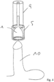
- Fig. 1 shows a typical urinal condom 1. This consists of an elastic material and forms a sheath that is rolled up in a ring shape. At the front end of the urinal condom there is a tube attachment.
- a receiving bell 5 has an inner bell-shaped cavity 6. This preferably has a shape that corresponds to the reception of a urinal condom of the intended size.
- a groove 7 running around the upper edge serves to receive the wound-up area of the urinal condom, the so-called condom ring.
- the receiving bell 5 is fluidically connected on the inside to a tubular channel 8 of the connecting unit 9.
- the receiving bell 5 and the connecting unit 9 are cylindrical on the outside.
- a flow-tight connection between the receiving bell 5 and the connecting unit 9 can be produced in any conventional way, pressing, screwing, using sealing rings and the like.
- a urinal condom can be inserted into the device in such a way that the non-wound area is received in the receiving bell and the hose attachment 3 is inserted into the tubular channel.
- the application is in the Figures 4 to 6
- the connecting unit which is connected to a device (not shown) for generating a negative pressure, called a vacuum pump, ensures that when the device is placed on a penis 10, the urinal condom 1 After placing it on the tip, it allows suction while supporting itself on the receiving bell.
- the negative pressure can be generated manually or electrically.
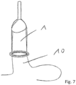
- the device After sucking the penis 10 into the urinal condom 1, as shown in Fig. 5 As shown, the device can be removed. A correspondingly higher static friction causes the condom to be removed from the receiving bell. This can be supported by switching off the negative pressure.
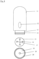
- the vacuum pump 11 is shown as an electric pump. This has an operating unit 12. This allows the pump to be switched on and off. At one end, the pump has a connection piece 13, which in the embodiment shown has a circumferential sealing ring 14.
- the view of the lower surface 15 below shows the suction channel 17 as a central opening. Elevations 16 are formed on the surface 15. These can be flat and their only function is to prevent direct suction of the surfaces lying against one another.
- the surface 18 of the connecting unit comes into contact with the surface 15. This has the opening 19, which represents the end of the suction channel of the connecting unit. In the embodiment shown, the surface 18 is surrounded by a sealing edge 20.
- connection piece 13 of the pump is inserted into the tube formed by the sealing edge 20 until the surface 15 comes to rest on the surface 18. They are only spaced apart from each other by the spacer elements 16.
- the inner transformation of the sealing edge 20 cooperates with the sealing ring 14 so that the negative pressure generated by the vacuum pump 11 is transferred to the suction channel of the connection unit via the opening 19.
- FIG 9 the receiving area of a receiving bell 21 is shown.
- a circumferential phase or groove 22 is worked out on the inner upper edge surrounding the air channel 23, whereby a receiving area 24 for the wound-up area of the urinal condom, the so-called condom ring, is formed.
- This condom ring protrudes slightly beyond the upper edge of the receiving bell 21.
- the outer upper edge of the receiving bell 21 makes the condom ring easier to reach and grasp.
- a large number of gripping grooves can be formed in the area of the upper edge.
Landscapes
- Health & Medical Sciences (AREA)
- Heart & Thoracic Surgery (AREA)
- Public Health (AREA)
- Vascular Medicine (AREA)
- Engineering & Computer Science (AREA)
- Biomedical Technology (AREA)
- Veterinary Medicine (AREA)
- Life Sciences & Earth Sciences (AREA)
- Animal Behavior & Ethology (AREA)
- General Health & Medical Sciences (AREA)
- Reproductive Health (AREA)
- Epidemiology (AREA)
- Nursing (AREA)
- Orthopedic Medicine & Surgery (AREA)
- Hematology (AREA)
- Anesthesiology (AREA)
- Orthopedics, Nursing, And Contraception (AREA)
Description
- Die vorliegende Erfindung betrifft ein System zum Anlegen eines Urinalkondoms zur bestimmungsgemäßen Verwendung.
- Eine mit zunehmender Überalterung der Gesellschaften ebenfalls zunehmende Behinderung ist die sogenannte Inkontinenz, auch als Blasenschwäche bezeichnet. Unkontrolliert auslaufende Flüssigkeit wird entweder mittels saugender Hilfsmittel aufgenommen, beispielsweise Windeln und dergleichen, oder abgeleitet.
- Zur Ableitung werden Katheter verwendet, die entweder durch die Bauchdecke direkt in die Blase eingesetzt werden, was häufig zu Infektionen führen kann, oder durch die Harnröhre des Penis in die Blase geschoben werden und zu Verletzungen an der Harnröhre führen können.
- Eine Alternative sind sogenannten Urinalkondome, die eine Verbindung mit einem abführenden Schlauch, mit Auffangbeuteln und dergleichen ermöglichen.
- Für die Versorgung der männlichen Harninkontinenz stellen Urinalkondome eine bevorzugte Alternative dar. Ein Nachteil besteht darin, dass das Anlegen eines Urinalkondoms schwierig sein kann. Bei eingeschränkter Fingerfertigkeit muss dies durch Fremdpersonen, Pflegepersonal oder dergleichen erfolgen. Aus unterschiedlichsten Gründen erweist sich dabei das ein Kondom aufnehmende Glied oftmals als wenig aufnahmefähig. Dies führt häufig zu Undichtigkeiten oder Faltungen, schlechten Sitz und dergleichen. Betroffene Patienten mit retrahiertem Penis oder mit Impotenz ist es bisher überhaupt nicht möglich, Urinalkondome anzusetzen und zu benutzen.
- Aus dem Stand der Technik ist aus der
CH 672 591 A5 - Dadurch bläht sich die am Auslassende verschlossene Manschette auf und erlaubt einen problemlosen Zugang in das Innere.
- Aus dem
EP 3346962 B1 , welches den nächsten Stand der Technik darstellt, ist eine gattungsgemäße Vorrichtung zum Anlegen eines Urinalkondoms zur bestimmungsgemäßen Verwendung bekannt, welche das Anlegen eines Urinalkondoms generell erheblich vereinfacht. Die bekannte Vorrichtung umfasst eine Aufnahmeglocke, eine Vakuumpumpe und eine Verbindungseinheit zur strömungstechnischen Verbindung der Aufnahmeglocke mit der Vakuumpumpe. Als Aufnahmeglocke wird ein topfförmiger Vorrichtungsteil bezeichnet, in welchen ein Urinalkondom einsetzbar ist. Urinalkondome liegen in der Regel in aufgerollter Form vor. Sie haben an der Spitze einen schlauchartigen Ansatz. Die Aufnahmeglocke wird so ausgestaltet, dass sie für die jeweilige Größe eines Urinalkondoms eine Möglichkeit zum Einlegen des Kondoms bietet, welches sich an die glockenförmige innere Oberfläche der Aufnahmevorrichtung anlegt. Der schlauchartige Ansatz ragt durch eine Öffnung an der entsprechenden Stelle der Aufnahmeglocke heraus. Die Verbindungseinheit hat einen rohrförmigen Kanal, so dass dann, wenn die Aufnahmeglocke mit der Verbindungseinheit verbunden ist, der Schlauchansatz eines eingelegten Kondoms in den Kanal ragt. Die Verbindungseinheit ist wiederum mit einer Vorrichtung zur Erzeugung eines Unterdruckes verbunden. Für die bestimmungsgemäße Verwendung wird in die Aufnahmeglocke ein Urinalkondom derart eingesetzt, dass der Schlauchansatz durch eine untere Öffnung der Aufnahmeglocke in den rohrförmigen Kanal der Verbindungseinheit ragt und der Kondomring an der freien Oberkante der Aufnahmeglocke zum Anliegen kommt. Der dazwischenliegende Kondombereich legt sich an den glockenförmig ausgebildeten Innenbereich der Aufnahmeglocke an. Die so vorbereitete Vorrichtung wird nun bestimmungsgemäß an einen Penis herangeführt und dieser wird aufgrund des durch den Betrieb der Vakuumpumpe erzeugten Unterdrucks in den an der Aufnahmeglocke anliegenden Bereich des Urinalkondoms eingesogen. Durch Abschalten der Vakuumpumpe kann nun die Vorrichtung abgenommen werden, so dass das Kondom am Glied verbleibt. Es kann nun in bestimmungsgemäßer Weise einfach abgerollt werden und ist somit optimal angesetzt. Auch ist ein Abnehmen der Vorrichtung bei laufender Vakuumpumpe, die unter Umständen regelbar ist, möglich, so dass in bestimmten Fällen auch ein faltenfreies Abrollen des Urinalkondoms unterstützt wird. - Bei der praktischen Anwendung hat sich herausgestellt, dass es im Bereich zwischen der Verbindungseinheit einerseits und der Vorrichtung zur Erzeugung des Unterdrucks andererseits zu unterschiedlichen Problemen kommt. Entweder ist die Verbindung nicht dicht genug, so dass der erzeugte Unterdruck nicht ausreicht, das Kondom vollständig in die Glocke zu saugen, oder die Verbindung ist so dicht, dass die Pumpe nicht mehr von der Verbindungseinheit gelöst werden kann, weil sich beide aneinander festgesaugt haben.
- Ausgehend vom vorbeschriebenen Stand der Technik liegt der vorliegenden Erfindung die Aufgabe zugrunde, ein System zum Anlegen eines Urinalkondoms der gattungsgemäßen Art in Bezug auf eine störungsfreie und sichere Benutzung zu verbessern, damit diese eine strömungsdichte Verbindung zwischen Vorrichtung zur Erzeugung eines Unterdruckes einerseits und der Verbindungseinheit andererseits sicherstellt, ohne die Lösbarkeit der beiden Einheiten voneinander zu behindern..
- Zur technischen Lösung wird eine Vorrichtung mit den Merkmalen des Patentanspruches 1 vorgeschlagen. Weitere Vorteile und Merkmale ergeben sich aus den Unteransprüchen.
- Das erfindungsgemäße System umfasst zum einen eine Vakuumpumpe und zum anderen eine Verbindungseinheit. Beide werden derart aneinandergesetzt, dass sie mit zueinander deckungsgleichen Oberflächen aneinander liegen. Wenigstens eine der beiden Oberflächen weist eine unebene Struktur auf. Auf Seiten der Vakuumpumpe mündet in der für die Verbindung vorgesehenen Oberfläche eine Saugöffnung. Auf Seiten der Verbindungseinheit mündet ein Saugkanal, der mit der Saugglocke bzw. Aufnahmeglocke verbunden ist. Werden die Vakuumpumpe und die Verbindungseinheit zusammengesetzt, kann der von der Vakuumpumpe erzeugte Unterdruck durch die Verbindungseinheit bis zur Aufnahmeglocke wirken. Um zu verhindern, dass sich die beiden aufeinanderliegenden Oberflächen aneinander festsaugen, wird wenigstens eine der beiden Oberflächen mit einer uneben Struktur versehen.
- Gemäß einem weiteren vorteilhaften Vorschlag der Erfindung werden die beiden aufeinanderliegenden Oberflächen randseitig abgedichtet. Dies kann auf unterschiedliche Weise erreicht werden. Beispielsweise kann ein umlaufende Dichtring zwischen beiden Oberflächen für eine Abdichtung sorgen. Gemäß einem vorteilhaften Vorschlag der Erfindung ist eine der Oberflächen mit einem ringförmigen Dichtrand umgeben, in welchen die jeweils andere Vorrichtung einsetzbar ist, um ihre zur Verbindung vorgesehene Oberfläche auf die andere Oberfläche aufzulegen. Zusätzlich kann der dichte Rand gegenüber dem Gehäuse durch einen weiteren Dichtring abgedichtet sein.
- Die Vorrichtung ihrerseits umfasst eine Aufnahmeglocke, eine Vakuumpumpe und eine Verbindungseinheit zur strömungstechnischen Verbindung der Aufnahmeglocke mit der Vakuumpumpe. Als Aufnahmeglocke wird ein topfförmiger Vorrichtungsteil bezeichnet, in welchen ein Urinalkondom einsetzbar ist. Urinalkondome liegen in der Regel in aufgerollter Form vor. Sie haben an der Spitze einen schlauchartigen Ansatz. Die Aufnahmeglocke wird so ausgestaltet, dass sie für die jeweilige Größe eines Urinalkondoms eine Möglichkeit zum Einlegen des Kondoms bietet, welches sich an die glockenförmige innere Oberfläche der Aufnahmevorrichtung anlegt. Der schlauchartige Ansatz ragt durch eine Öffnung an der entsprechenden Stelle der Aufnahmeglocke heraus.
- Eine Verbindungseinheit hat einen rohrförmigen Kanal, so dass dann, wenn die Aufnahmeglocke mit der Verbindungseinheit verbunden ist, der Schlauchansatz eines eingelegten Kondoms in den Kanal ragt. Die Verbindungseinheit ist wiederum mit einer Vorrichtung zur Erzeugung eines Unterdruckes verbunden. Dies kann ein Pumpball oder eine Pumpschere sein, die manuell betätigt werden, oder eine Elektropumpe für den Netzbetrieb oder Batteriebetrieb. Im einfachsten Fall ist die Verbindungseinheit lediglich ein Schlauch, der an der Aufnahmeglocke derart befestigt ist, dass er den Schlauchansatz eines eingesetzten Kondoms aufnehmen kann und die Vakuumpumpe strömungstechnisch mit dem Innenraum der Aufnahmegtocke verbindet. Um das Anlegen zu optimieren, ist die Innenkontur der Aufnahmeglocke so ausgearbeitet, dass sie ein Urinalkondom einer vorgegebenen Größe passgenau aufnehmen kann. Dadurch wird Faltenbildung vermieden und ein optimales Ansetzen unterstützt. An der bestimmungsgemäß äußeren Oberkante, das heißt die freie Oberkante die nicht mit einer Verbindungseinheit verbunden wird, weist die Aufnahmeglocke gemäß einem vorteilhaften Vorschlage der Erfindung eine umlaufende Nut auf. Diese dient dem Zweck, den Kondomring, der sich durch das Aufrollen des Urinalkondoms ergibt, aufzunehmen, wenn das Urinalkondom in die Aufnahmeglocke eingesetzt wird. Im Falle, dass keine Nut ausgebildet ist, ist erfindungsgemäß auch vorgesehen, dass der Kondomring an den Rändern der Aufnahmeglocke übergestülpt oder beispielsweise mit einem Klemmring befestigt wird.
- In vorteilhafter Weise ist die Aufnahmeglocke außenseitig zylindrisch, um für eine gute Handhabung eine entsprechende Haptik bereitzustellen. Um für unterschiedliche Urinalkondome einsetzbar zu sein, kann die Aufnahmeglocke austauschbar mit der Verbindungseinheit verbunden werden. Auf diese Weise kann die Verbindungseinheit mit Aufnahmeglocken unterschiedlicher Größe und Ausbildung verbindbar sein.
- Die gesamte Vorrichtung kann mit einem integrierenden Gehäuse versehen sein, in welches beispielsweise eine batteriebetriebene Elektropumpe, ein Verbindungskanal und eine Aufnahmeglocke untergebracht sind, wobei die Aufnahmeglocke in einem lösbaren Gehäuseteil angeordnet sein kann.
- Für die bestimmungsgemäße Verwendung wird in die Aufnahmeglocke ein Urinalkondom derart eingesetzt, dass der Schlauchansatz durch eine untere Öffnung der Aufnahmeglocke in den rohrförmigen Kanal der Verbindungseinheit ragt und der Kondomring an der freien Oberkante der Aufnahmeglocke zum anliegen kommt. Der dazwischenliegende Kondombereich legt sich an den glockenförmig ausgebildeten Innenbereich der Aufnahmeglocke an. Die so vorbereitete Vorrichtung wird nun bestimmungsgemäß an einen Penis herangeführt und dieser wird aufgrund des durch den Betrieb der Vakuumpumpe erzeugten Unterdrucks in den an der Aufnahmeglocke anliegenden Bereich des Urinalkondoms eingesogen. Dabei werden Größen, Weichheiten und dergleichen durch einfaches Einsaugen kompensiert, so dass das Urinalkondom optimal angesetzt ist. Durch Abschalten der Vakuumpumpe kann nun die Vorrichtung abgenommen werden, so dass das Kondom am Glied verbleibt. Es kann nun in bestimmungsgemäßer Weise einfach abgerollt werden und ist somit optimal angesetzt. Auch ist ein Abnehmen der Vorrichtung bei laufender Vakuumpumpe, die unter Umständen regelbar ist, möglich, so dass in bestimmten Fällen auch ein faltenfreies Abrollen des Urinalkondoms unterstützt wird.
- Mit der Erfindung wird eine einfach herstellbare und vor allem einfach anwendbare Vorrichtung bereitgestellt, mit welcher das Anlegen eines Urinalkondoms zur bestimmungsgemäßen Verwendung erheblich vereinfacht und optimiert wird.
- Weitere Vorteile und Merkmale ergeben sich aus der folgenden Beschreibung anhand der Figuren. Dabei zeigen:
- Fig.1
- eine schematische Darstellung eines typischen Urinalkondoms;
- Fig.2
- eine schematische Darstellung einer Aufnahmeglocke und einer Verbindungseinheit;
- Fig.3
- eine Darstellung gemäß
Fig. 2 mit eingesetztem Urinalkondom; - Fig.4
- eine Darstellung des Ansetzvorganges der erfindungsgemäßen Vorrichtung zum Anlegen des Kondoms zur bestimmungsgemäßen Verwendung;
- Fig.5
- eine Darstellung gemäß
Fig. 4 in einer fortgeführten Position; - Fig.6
- eine Darstellung gemäß
Fig. 4 in einer abschließenden Position; - Fig.7
- eine Darstellung des Urinalkondoms in bestimmungsgemäßer Position;
- Fig.8
- eine Darstellung der Verbindungsoberflächen zwischen Vakuumpumpe und Verbindungseinheit, und
- Fig. 9
- eine Darstellung des oberen Aufnahmebereiches einer Aufnahmeglocke.
-
Fig. 1 zeigt ein typisches Urinalkondom 1. Dieses besteht aus einem elastischen Material und bildet eine Hülle, die ringförmig aufgerollt ist. Am vorderen Ende des Urinalkondoms befindet sich ein Schlauchansatz. - Die Aufwicklung 2 dient der Vereinfachung des Anlegens des Kondoms, der Schlauchansatz 3 der Abführung. In den
Figuren 2 und 3 ist ein Ausführungsbeispiel für eine erfindungsgemäße Vorrichtung gezeigt. Eine Aufnahmeglocke 5 weist einen inneren glockenförmigen Hohlraum 6 auf. Dieser hat vorzugsweise eine Form, die der Aufnahme eines Urinalkondoms in der vorgesehenen Größe entspricht. Eine an der Oberkante umlaufende Nut 7 dient der Aufnahme des aufgewickelten Bereiches des Urinalkondoms, dem sogenannten Kondomring. Die Aufnahmeglocke 5 ist im Inneren strömungstechnisch verbunden mit einem rohrförmigen Kanal 8 der Verbindungseinheit 9. Die Aufnahmeglocke 5 und die Verbindungseinheit 9 sind außenseitig zylindrisch ausgebildet. Eine strömungsdichte Verbindung zwischen Aufnahmeglocke 5 und Verbindungseinheit 9 kann auf jede herkömmliche Weise hergestellt werden, verpressen, verschrauben, unter Verwendung von Dichtringen und dergleichen. - Wie insbesondere
Fig. 3 zeigt, lässt sich in die Vorrichtung ein Urinalkondom derart einsetzen, dass der nicht aufgewickelte Bereich in der Aufnahmeglocke aufgenommen wird und der Schlauchansatz 3 in den rohrförmigen Kanal eingesetzt ist. - Die Applikation ist in den
Figuren 4 bis 6 gezeigt. Die mit einer nicht gezeigten Vorrichtung zur Erzeugung eines Unterdrucks, Vakuumpumpe genannt, verbundene Verbindungseinheit stellt sicher, dass beim Aufsetzen der Vorrichtung auf einen Penis 10 das Urinalkondom 1 nach dem Aufsetzen auf die Spitze ein Einsaugen zulässt, während es sich selbst an der Aufnahmeglocke abstützt. Der Unterdruck kann manuell oder elektrisch erzeugt werden. Nach dem Einsaugen des Penis 10 in das Urinalkondom 1, wie dies inFig. 5 gezeigt ist, kann die Vorrichtung abgenommen werden. Eine entsprechend höhere Haftreibung bewirkt, dass das Kondom aus der Aufnahmeglocke abgenommen wird. Dies kann durch Abschalten des Unterdrucks unterstützt werden. - Wie in
Fig. 7 gezeigt, ist nunmehr nur noch ein übliches Abrollen des aufgerollten Kondombereiches erforderlich. - In
Fig.8 ist das erfindungsgemäße Zusammenwirken der Elemente gezeigt. Im gezeigten Ausführungsbeispiel ist die Vakuumpumpe 11 als elektrische Pumpe dargestellt. Diese hat eine Bedienungseinheit 12. Damit lässt sich die Pumpe an und abschalten. An einem Ende weist die Pumpe einen Anschlussstutzen 13 auf, welcher im gezeigten Ausführungsbeispiel einen umlaufenden Dichtring 14 trägt. Die unter Ansicht der unteren Oberfläche 15 zeigt den Saugkanal 17 als mittlere Öffnung. Auf der Oberfläche 15 sind Erhebungen 16 ausgebildet. Diese können flach sein und ihre einzige Funktion besteht darin, ein direktes Ansaugen der aneinander liegenden Oberflächen zu verhindern. - An der Oberfläche 15 kommt die Oberfläche ab 18 der Verbindungseinheit zur Anlage. Diese weist die Öffnung 19 auf, die das Ende des Saugkanals der Verbindungseinheit darstellt. Im gezeigten Ausführungsbeispiel ist die Oberfläche 18 von einem Dichtrand 20 umgeben.
- Im Zusammenwirken wird der Anschlussstutzen 13 der Pumpe in die durch den Dichterang 20 gebildete Röhre eingesteckt, bis die Oberfläche 15 auf der Oberfläche 18 zu liegen kommt. Sie sind lediglich durch die Abstandselemente 16 voneinander beanstandet. Die innere Wandlung des Dichtrandes 20 wirkt mit dem Dichtring 14 zusammen, so dass der von der Vakuumpumpe 11 erzeugte Unterdruck auf den Saugkanal der Verbindungseinheit über die Öffnung 19 übertragen wird.
- In
Figur 9 ist der Aufnahmebereich einer Aufnahmeglocke 21 gezeigt. Den Luftkanal 23 umgebend ist an der inneren Oberkante eine umlaufende Phase oder Nut 22 ausgearbeitet, wodurch ein Aufnahmebereich 24 für den aufgewickelten Bereiches des Urinalkondoms, den sogenannten Kondomring, gebildet ist. Dieser Kondomring steht etwas über die Oberkante der Aufnahmeglocke 21 hinaus. Durch die Greifnut 25, eine Art Aussparung oder Senke im Bereich der äußeren Oberkante der Aufnahmeglocke 21 wird der Kondomring leichter erreichbar und ergreifbar. Im Bereich der Oberkante können eine Vielzahl von Greifnuten ausgebildet sein. - Das beschriebene Ausführungsbeispiel dient nur der Erläuterung und ist nicht beschränkend.
-
- 1 Urinalkondom
- 2 Aufwicklung
- 3 Schlauchansatz
- 5 Aufnahmeglocke
- 6 Hohlraum
- 7 Nut
- 8 rohrförmiger Kanal
- 9 Verbindungseinheit
- 10 Penis
- 11 Vakuumpumpe
- 12 Bedieneinheit
- 13 Anschluss-Stutzen
- 14 Dichtring
- 15 Anschluss-Stutzen untere Oberfläche
- 16 Abstandselemente
- 17 Saug-Kanal
- 18 Anschlussstelle Verbindungseinheit
- 19 Saug-Kanal
- 20 Dichtrand
- 21 Aufnahmeglocke
- 22 Nut
- 23 Kanal
- 24 Aufnahmebereich
- 25 Greifnut
Claims (10)
- System zum Anlegen eines Urinalkondoms (1) zur bestimmungsgemäßen Verwendung, mit einer Aufnahmeglocke (5), einer Vakuumpumpe (11) und einer Verbindungseinheit (9) zur strömungstechnischen Verbindung der Aufnahmeglocke (5) mit der Vakuumpumpe, wobei die Verbindungseinheit (9) einen rohrförmigen Kanal (8) aufweist, mit dem die Aufnahmeglocke (5) strömungstechnisch verbunden ist, wobei der rohrförmige Kanal (8) aufnahmeglockenseitig als Aufnahme für einen Schlauchansatz des Urinalkondoms ausgebildet ist, dadurch gekennnzeichnet, dass die Verbindungseinheit an der mit der Vakuumpumpe zu verbindenden Seite eine Oberfläche (18) aufweist, welche zu einer an der Vakuumpumpe ausgebildeten Oberfläche (15) deckungsgleich ist, wobei wenigstens eine der beiden Oberflächen eine unebene Struktur aufweist, und die Vakuumpumpe und die Verbindungseinheit über die beiden aufeinanderliegenden Oberflächen strömungstechnisch verbunden sind.
- System nach Anspruch 1, dadurch gekennzeichnet, dass die beiden aufeinanderliegenden Oberflächen randseitig abgedichtet sind.
- System nach Anspruch 2, dadurch gekennzeichnet, dass eine der beiden Oberflächen der Verbindungseinheit oder der Vakuumpumpe durch einen Dichtrand (20) umgeben ist, in welchen das jeweils andere Element strömungsdicht einsetzbar ist.
- System nach einem der vorhergehenden Ansprüche, dadurch gekennzeichnet, dass zwischen dem Dichtrand und der mit diesem zusammenwirkenden Oberfläche eine Dichtung (14) eingelegt ist.
- System nach einem der vorhergehenden Ansprüche, dadurch gekennzeichnet, dass die Aufnahmeglocke (5) an einer Oberkante eine umlaufende Nut (7) aufweist.
- System nach Anspruch 5, dadurch gekennzeichnet, dass die Aufnahmeglocke außenseitig im Bereich der Oberkante Greifnuten aufweist.
- System nach einem der vorhergehenden Ansprüche, dadurch gekennzeichnet, dass die Aufnahmeglocke (5) außenseitig zylindrisch ist.
- System nach einem der vorhergehenden Ansprüche, dadurch gekennzeichnet, dass die Aufnahmeglocke (5) lösbar mit der Verbindungseinheit (9) verbunden ist.
- System nach einem der vorhergehenden Ansprüche, dadurch gekennzeichnet, dass die Verbindungseinheit (9) im Wesentlichen zylindrisch ausgearbeitet ist.
- System nach einem der vorhergehenden Ansprüche, dadurch gekennzeichnet, dass die Aufnahmeglocke (5) und die Verbindungseinheit (9) aus Kunststoff bestehen.
Priority Applications (5)
| Application Number | Priority Date | Filing Date | Title |
|---|---|---|---|
| EP22000138.2A EP4282387B1 (de) | 2022-05-25 | 2022-05-25 | System zum anlegen eines urinalkondoms |
| PL22000138.2T PL4282387T3 (pl) | 2022-05-25 | 2022-05-25 | System nakładania kondomu urologicznego |
| ES22000138T ES3014609T3 (en) | 2022-05-25 | 2022-05-25 | Urinary condom application system |
| PCT/IB2023/055332 WO2023228101A1 (de) | 2022-05-25 | 2023-05-24 | System zum anlegen eines urinalkondoms |
| US18/868,418 US20250325396A1 (en) | 2022-05-25 | 2023-05-24 | System for applying a urinal condom |
Applications Claiming Priority (1)
| Application Number | Priority Date | Filing Date | Title |
|---|---|---|---|
| EP22000138.2A EP4282387B1 (de) | 2022-05-25 | 2022-05-25 | System zum anlegen eines urinalkondoms |
Publications (2)
| Publication Number | Publication Date |
|---|---|
| EP4282387A1 EP4282387A1 (de) | 2023-11-29 |
| EP4282387B1 true EP4282387B1 (de) | 2024-12-11 |
Family
ID=81878136
Family Applications (1)
| Application Number | Title | Priority Date | Filing Date |
|---|---|---|---|
| EP22000138.2A Active EP4282387B1 (de) | 2022-05-25 | 2022-05-25 | System zum anlegen eines urinalkondoms |
Country Status (5)
| Country | Link |
|---|---|
| US (1) | US20250325396A1 (de) |
| EP (1) | EP4282387B1 (de) |
| ES (1) | ES3014609T3 (de) |
| PL (1) | PL4282387T3 (de) |
| WO (1) | WO2023228101A1 (de) |
Family Cites Families (5)
| Publication number | Priority date | Publication date | Assignee | Title |
|---|---|---|---|---|
| US2567926A (en) * | 1946-03-01 | 1951-09-18 | Milton S Dunkelberger | Tubular supporting member |
| CH672591A5 (en) | 1986-11-03 | 1989-12-15 | Eugene Fischer | Urine collector for male incontinent patient - has flexible stretched over open top of vessel and expanded by suction device |
| US5471998A (en) * | 1993-12-27 | 1995-12-05 | Kuyumciyan; Levon | Condom applicator |
| DE102007020517B3 (de) * | 2007-05-02 | 2008-07-03 | Reinhard Badewien | Vorrichtung zum Auffangen und Ableiten von Urin für Männer |
| WO2017042344A1 (de) | 2015-09-10 | 2017-03-16 | Ehrensperger Samuel M | VORRICHTUNG ZUM ANLEGEN EINES URINALKONDOMS ZUR BESTIMMUNGSGEMÄßEN VERWENDUNG |
-
2022
- 2022-05-25 EP EP22000138.2A patent/EP4282387B1/de active Active
- 2022-05-25 PL PL22000138.2T patent/PL4282387T3/pl unknown
- 2022-05-25 ES ES22000138T patent/ES3014609T3/es active Active
-
2023
- 2023-05-24 WO PCT/IB2023/055332 patent/WO2023228101A1/de not_active Ceased
- 2023-05-24 US US18/868,418 patent/US20250325396A1/en active Pending
Also Published As
| Publication number | Publication date |
|---|---|
| US20250325396A1 (en) | 2025-10-23 |
| EP4282387A1 (de) | 2023-11-29 |
| WO2023228101A1 (de) | 2023-11-30 |
| ES3014609T3 (en) | 2025-04-23 |
| PL4282387T3 (pl) | 2025-04-07 |
Similar Documents
| Publication | Publication Date | Title |
|---|---|---|
| DE69316615T2 (de) | Vorrichtung zur behandlung von weiblicher inkontinenz | |
| EP0366870B1 (de) | Ureterschiene mit Klemmverbindung zu einem Vorschubschlauch | |
| EP0543284B1 (de) | Medizinisches Instrument mit einer Einrichtung zum Führen im Darm | |
| EP0088871B1 (de) | Katheterventil | |
| DE4014369A1 (de) | Harnroehrenverweilkatheter mit inkontinenzsteuerung und verfahren | |
| DE3609079A1 (de) | Harnableitungskatheter mit anlegehilfe fuer maennliche patienten | |
| DE2628719A1 (de) | Verbindungsstueck zur entnahme von fluessigkeitsproben aus einer geschlossenen anordnung zur ableitung einer fluessigkeit | |
| DE2430131A1 (de) | Vorrichtung zur superapubischen katheterisierung | |
| DE2005167B2 (de) | Postoperative Drain-Röhre | |
| DE9404048U1 (de) | Vorrichtung für den Vakuum-Wundverschluß und/oder zum Absaugen von Sekret o.dgl. | |
| WO1991017729A1 (de) | Gerät für die spülung und drainierung von wunden | |
| EP0666064A1 (de) | Schutzvorrichtung für den unkontrollierten Abfluss von Urin | |
| DE19733665C2 (de) | Vorrichtung zur kombinierten Urinableitung und Katheterisierung inkontinenter männlicher Personen | |
| EP4282387B1 (de) | System zum anlegen eines urinalkondoms | |
| DE69212407T2 (de) | Ostomierirrigationseinrichtung zum Einbringen radiologischer Flüssigkeiten | |
| DE3000322C2 (de) | Vorrichtung zur Abführung von Fluida aus einer Wunde | |
| DE69625063T2 (de) | Harninkontinenzvorrichtung für frauen | |
| EP3346962B1 (de) | Vorrichtung zum anlegen eines urinalkondoms zur bestimmungsgemaessen verwendung | |
| WO2013117635A1 (de) | Vorrichtung zur urinableitung bei männlichen inkontinenzpatienten | |
| EP2680805B1 (de) | Vorrichtung zur pneumatischen, rekto-sigmoidalen triggerung eines defäkationsreflexes | |
| DE112008003106T5 (de) | Katheter und Katheter-Kit | |
| DE19926362C1 (de) | Vorrichtung zur kombinierten Urinableitung und Katheterisierung inkontinenter männlicher Personen | |
| DE29513921U1 (de) | Vorrichtung zum Verschließen einer Harnröhre | |
| EP2465477B1 (de) | Vorrichtung zur Ableitung von unkontrolliertem Harnabgang | |
| DE2516640C3 (de) | Gerät zum Applizieren und/oder Entnehmen von Substanzen in bzw. aus oberflächennahen Körperhöhlen |
Legal Events
| Date | Code | Title | Description |
|---|---|---|---|
| PUAI | Public reference made under article 153(3) epc to a published international application that has entered the european phase |
Free format text: ORIGINAL CODE: 0009012 |
|
| STAA | Information on the status of an ep patent application or granted ep patent |
Free format text: STATUS: THE APPLICATION HAS BEEN PUBLISHED |
|
| AK | Designated contracting states |
Kind code of ref document: A1 Designated state(s): AL AT BE BG CH CY CZ DE DK EE ES FI FR GB GR HR HU IE IS IT LI LT LU LV MC MK MT NL NO PL PT RO RS SE SI SK SM TR |
|
| STAA | Information on the status of an ep patent application or granted ep patent |
Free format text: STATUS: REQUEST FOR EXAMINATION WAS MADE |
|
| 17P | Request for examination filed |
Effective date: 20240527 |
|
| RBV | Designated contracting states (corrected) |
Designated state(s): AL AT BE BG CH CY CZ DE DK EE ES FI FR GB GR HR HU IE IS IT LI LT LU LV MC MK MT NL NO PL PT RO RS SE SI SK SM TR |
|
| GRAP | Despatch of communication of intention to grant a patent |
Free format text: ORIGINAL CODE: EPIDOSNIGR1 |
|
| STAA | Information on the status of an ep patent application or granted ep patent |
Free format text: STATUS: GRANT OF PATENT IS INTENDED |
|
| INTG | Intention to grant announced |
Effective date: 20240717 |
|
| GRAS | Grant fee paid |
Free format text: ORIGINAL CODE: EPIDOSNIGR3 |
|
| GRAA | (expected) grant |
Free format text: ORIGINAL CODE: 0009210 |
|
| STAA | Information on the status of an ep patent application or granted ep patent |
Free format text: STATUS: THE PATENT HAS BEEN GRANTED |
|
| AK | Designated contracting states |
Kind code of ref document: B1 Designated state(s): AL AT BE BG CH CY CZ DE DK EE ES FI FR GB GR HR HU IE IS IT LI LT LU LV MC MK MT NL NO PL PT RO RS SE SI SK SM TR |
|
| RAP1 | Party data changed (applicant data changed or rights of an application transferred) |
Owner name: URISAN GMBH |
|
| REG | Reference to a national code |
Ref country code: GB Ref legal event code: FG4D Free format text: NOT ENGLISH |
|
| RIN1 | Information on inventor provided before grant (corrected) |
Inventor name: EHRENSPERGER, SAMUEL |
|
| REG | Reference to a national code |
Ref country code: CH Ref legal event code: EP |
|
| REG | Reference to a national code |
Ref country code: DE Ref legal event code: R096 Ref document number: 502022002332 Country of ref document: DE |
|
| REG | Reference to a national code |
Ref country code: IE Ref legal event code: FG4D Free format text: LANGUAGE OF EP DOCUMENT: GERMAN |
|
| REG | Reference to a national code |
Ref country code: LT Ref legal event code: MG9D |
|
| PG25 | Lapsed in a contracting state [announced via postgrant information from national office to epo] |
Ref country code: HR Free format text: LAPSE BECAUSE OF FAILURE TO SUBMIT A TRANSLATION OF THE DESCRIPTION OR TO PAY THE FEE WITHIN THE PRESCRIBED TIME-LIMIT Effective date: 20241211 |
|
| PG25 | Lapsed in a contracting state [announced via postgrant information from national office to epo] |
Ref country code: FI Free format text: LAPSE BECAUSE OF FAILURE TO SUBMIT A TRANSLATION OF THE DESCRIPTION OR TO PAY THE FEE WITHIN THE PRESCRIBED TIME-LIMIT Effective date: 20241211 |
|
| PG25 | Lapsed in a contracting state [announced via postgrant information from national office to epo] |
Ref country code: BG Free format text: LAPSE BECAUSE OF FAILURE TO SUBMIT A TRANSLATION OF THE DESCRIPTION OR TO PAY THE FEE WITHIN THE PRESCRIBED TIME-LIMIT Effective date: 20241211 |
|
| PG25 | Lapsed in a contracting state [announced via postgrant information from national office to epo] |
Ref country code: NO Free format text: LAPSE BECAUSE OF FAILURE TO SUBMIT A TRANSLATION OF THE DESCRIPTION OR TO PAY THE FEE WITHIN THE PRESCRIBED TIME-LIMIT Effective date: 20250311 |
|
| REG | Reference to a national code |
Ref country code: ES Ref legal event code: FG2A Ref document number: 3014609 Country of ref document: ES Kind code of ref document: T3 Effective date: 20250423 |
|
| PG25 | Lapsed in a contracting state [announced via postgrant information from national office to epo] |
Ref country code: LV Free format text: LAPSE BECAUSE OF FAILURE TO SUBMIT A TRANSLATION OF THE DESCRIPTION OR TO PAY THE FEE WITHIN THE PRESCRIBED TIME-LIMIT Effective date: 20241211 Ref country code: GR Free format text: LAPSE BECAUSE OF FAILURE TO SUBMIT A TRANSLATION OF THE DESCRIPTION OR TO PAY THE FEE WITHIN THE PRESCRIBED TIME-LIMIT Effective date: 20250312 |
|
| PG25 | Lapsed in a contracting state [announced via postgrant information from national office to epo] |
Ref country code: RS Free format text: LAPSE BECAUSE OF FAILURE TO SUBMIT A TRANSLATION OF THE DESCRIPTION OR TO PAY THE FEE WITHIN THE PRESCRIBED TIME-LIMIT Effective date: 20250311 |
|
| PG25 | Lapsed in a contracting state [announced via postgrant information from national office to epo] |
Ref country code: NL Free format text: LAPSE BECAUSE OF FAILURE TO SUBMIT A TRANSLATION OF THE DESCRIPTION OR TO PAY THE FEE WITHIN THE PRESCRIBED TIME-LIMIT Effective date: 20241211 |
|
| PG25 | Lapsed in a contracting state [announced via postgrant information from national office to epo] |
Ref country code: SM Free format text: LAPSE BECAUSE OF FAILURE TO SUBMIT A TRANSLATION OF THE DESCRIPTION OR TO PAY THE FEE WITHIN THE PRESCRIBED TIME-LIMIT Effective date: 20241211 |
|
| PGFP | Annual fee paid to national office [announced via postgrant information from national office to epo] |
Ref country code: DE Payment date: 20250526 Year of fee payment: 4 Ref country code: PL Payment date: 20250521 Year of fee payment: 4 |
|
| PGFP | Annual fee paid to national office [announced via postgrant information from national office to epo] |
Ref country code: ES Payment date: 20250602 Year of fee payment: 4 |
|
| PG25 | Lapsed in a contracting state [announced via postgrant information from national office to epo] |
Ref country code: IS Free format text: LAPSE BECAUSE OF FAILURE TO SUBMIT A TRANSLATION OF THE DESCRIPTION OR TO PAY THE FEE WITHIN THE PRESCRIBED TIME-LIMIT Effective date: 20250411 |
|
| PGFP | Annual fee paid to national office [announced via postgrant information from national office to epo] |
Ref country code: BE Payment date: 20250526 Year of fee payment: 4 |
|
| PG25 | Lapsed in a contracting state [announced via postgrant information from national office to epo] |
Ref country code: PT Free format text: LAPSE BECAUSE OF FAILURE TO SUBMIT A TRANSLATION OF THE DESCRIPTION OR TO PAY THE FEE WITHIN THE PRESCRIBED TIME-LIMIT Effective date: 20250411 |
|
| PG25 | Lapsed in a contracting state [announced via postgrant information from national office to epo] |
Ref country code: EE Free format text: LAPSE BECAUSE OF FAILURE TO SUBMIT A TRANSLATION OF THE DESCRIPTION OR TO PAY THE FEE WITHIN THE PRESCRIBED TIME-LIMIT Effective date: 20241211 |
|
| PGFP | Annual fee paid to national office [announced via postgrant information from national office to epo] |
Ref country code: FR Payment date: 20250523 Year of fee payment: 4 |
|
| PG25 | Lapsed in a contracting state [announced via postgrant information from national office to epo] |
Ref country code: RO Free format text: LAPSE BECAUSE OF FAILURE TO SUBMIT A TRANSLATION OF THE DESCRIPTION OR TO PAY THE FEE WITHIN THE PRESCRIBED TIME-LIMIT Effective date: 20241211 |
|
| PGFP | Annual fee paid to national office [announced via postgrant information from national office to epo] |
Ref country code: AT Payment date: 20250721 Year of fee payment: 4 |
|
| PG25 | Lapsed in a contracting state [announced via postgrant information from national office to epo] |
Ref country code: SK Free format text: LAPSE BECAUSE OF FAILURE TO SUBMIT A TRANSLATION OF THE DESCRIPTION OR TO PAY THE FEE WITHIN THE PRESCRIBED TIME-LIMIT Effective date: 20241211 |
|
| PGFP | Annual fee paid to national office [announced via postgrant information from national office to epo] |
Ref country code: TR Payment date: 20250521 Year of fee payment: 4 |
|
| PG25 | Lapsed in a contracting state [announced via postgrant information from national office to epo] |
Ref country code: CZ Free format text: LAPSE BECAUSE OF FAILURE TO SUBMIT A TRANSLATION OF THE DESCRIPTION OR TO PAY THE FEE WITHIN THE PRESCRIBED TIME-LIMIT Effective date: 20241211 |
|
| PG25 | Lapsed in a contracting state [announced via postgrant information from national office to epo] |
Ref country code: IT Free format text: LAPSE BECAUSE OF FAILURE TO SUBMIT A TRANSLATION OF THE DESCRIPTION OR TO PAY THE FEE WITHIN THE PRESCRIBED TIME-LIMIT Effective date: 20241211 |
|
| PG25 | Lapsed in a contracting state [announced via postgrant information from national office to epo] |
Ref country code: SE Free format text: LAPSE BECAUSE OF FAILURE TO SUBMIT A TRANSLATION OF THE DESCRIPTION OR TO PAY THE FEE WITHIN THE PRESCRIBED TIME-LIMIT Effective date: 20241211 |
|
| REG | Reference to a national code |
Ref country code: DE Ref legal event code: R097 Ref document number: 502022002332 Country of ref document: DE |
|
| PG25 | Lapsed in a contracting state [announced via postgrant information from national office to epo] |
Ref country code: DK Free format text: LAPSE BECAUSE OF FAILURE TO SUBMIT A TRANSLATION OF THE DESCRIPTION OR TO PAY THE FEE WITHIN THE PRESCRIBED TIME-LIMIT Effective date: 20241211 |
|
| PLBE | No opposition filed within time limit |
Free format text: ORIGINAL CODE: 0009261 |
|
| STAA | Information on the status of an ep patent application or granted ep patent |
Free format text: STATUS: NO OPPOSITION FILED WITHIN TIME LIMIT |
|
| 26N | No opposition filed |
Effective date: 20250912 |