EP4276392B1 - Kühlbox - Google Patents
Kühlbox Download PDFInfo
- Publication number
- EP4276392B1 EP4276392B1 EP22766699.7A EP22766699A EP4276392B1 EP 4276392 B1 EP4276392 B1 EP 4276392B1 EP 22766699 A EP22766699 A EP 22766699A EP 4276392 B1 EP4276392 B1 EP 4276392B1
- Authority
- EP
- European Patent Office
- Prior art keywords
- sliding door
- porous body
- side sliding
- water
- stile
- Prior art date
- Legal status (The legal status is an assumption and is not a legal conclusion. Google has not performed a legal analysis and makes no representation as to the accuracy of the status listed.)
- Active
Links
Images


Classifications
-
- F—MECHANICAL ENGINEERING; LIGHTING; HEATING; WEAPONS; BLASTING
- F25—REFRIGERATION OR COOLING; COMBINED HEATING AND REFRIGERATION SYSTEMS; HEAT PUMP SYSTEMS; MANUFACTURE OR STORAGE OF ICE; LIQUEFACTION SOLIDIFICATION OF GASES
- F25D—REFRIGERATORS; COLD ROOMS; ICE-BOXES; COOLING OR FREEZING APPARATUS NOT OTHERWISE PROVIDED FOR
- F25D21/00—Defrosting; Preventing frosting; Removing condensed or defrost water
- F25D21/14—Collecting or removing condensed and defrost water; Drip trays
-
- F—MECHANICAL ENGINEERING; LIGHTING; HEATING; WEAPONS; BLASTING
- F28—HEAT EXCHANGE IN GENERAL
- F28D—HEAT-EXCHANGE APPARATUS, NOT PROVIDED FOR IN ANOTHER SUBCLASS, IN WHICH THE HEAT-EXCHANGE MEDIA DO NOT COME INTO DIRECT CONTACT
- F28D20/00—Heat storage plants or apparatus in general; Regenerative heat-exchange apparatus not covered by groups F28D17/00 or F28D19/00
- F28D20/0034—Heat storage plants or apparatus in general; Regenerative heat-exchange apparatus not covered by groups F28D17/00 or F28D19/00 using liquid heat storage material
-
- F—MECHANICAL ENGINEERING; LIGHTING; HEATING; WEAPONS; BLASTING
- F25—REFRIGERATION OR COOLING; COMBINED HEATING AND REFRIGERATION SYSTEMS; HEAT PUMP SYSTEMS; MANUFACTURE OR STORAGE OF ICE; LIQUEFACTION SOLIDIFICATION OF GASES
- F25D—REFRIGERATORS; COLD ROOMS; ICE-BOXES; COOLING OR FREEZING APPARATUS NOT OTHERWISE PROVIDED FOR
- F25D23/00—General constructional features
- F25D23/02—Doors; Covers
- F25D23/021—Sliding doors
-
- F—MECHANICAL ENGINEERING; LIGHTING; HEATING; WEAPONS; BLASTING
- F25—REFRIGERATION OR COOLING; COMBINED HEATING AND REFRIGERATION SYSTEMS; HEAT PUMP SYSTEMS; MANUFACTURE OR STORAGE OF ICE; LIQUEFACTION SOLIDIFICATION OF GASES
- F25D—REFRIGERATORS; COLD ROOMS; ICE-BOXES; COOLING OR FREEZING APPARATUS NOT OTHERWISE PROVIDED FOR
- F25D2321/00—Details or arrangements for defrosting; Preventing frosting; Removing condensed or defrost water, not provided for in other groups of this subclass
- F25D2321/14—Collecting condense or defrost water; Removing condense or defrost water
- F25D2321/147—Collecting condense or defrost water; Removing condense or defrost water characterised by capillary, wick, adsorbent, or evaporation elements
Definitions
- the present disclosure relates to a cold storage.
- Patent Literature (PTL) 1 discloses a sash in which a guide groove for dew condensation water is formed in each of an upper frame of a sash window frame and a sash door stile to prevent intrusion of the dew condensation water into a room.
- the dew condensation water is guided to a lower frame of the sash window frame through the guide groove.
- the dew condensation water guided to the lower frame is drained through, for example, a drain hole formed in the lower frame.
- a relatively large amount of dew condensation water generates on a sliding door for opening and closing the storage chamber and on a frame to which the sliding door is attached, and the dew condensation water flows down toward a lower frame.
- the dew condensation water may remain on the lower frame in some cases without being completely drained through a drain hole.
- An object of the present disclosure is to increase the efficiency in draining the dew condensation water in a cold storage.
- a cold storage of the present disclosure includes: a box with an opening at front; a frame bordering the opening; a sliding door attached to the frame and including, in at least one of a left-side end portion and a right-side end portion, a drain channel extending vertically; and a porous body with water permeability, the porous body being attached to an upper surface of the sliding door to establish fluid communication with the drain channel.
- the efficiency in draining the dew condensation water can be increased.
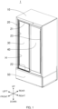
- a side where left-side sliding door 30 and right-side sliding door 40 are disposed is a front side with respect to cold storage 1, and a side opposite to the above side is a rear side with respect to cold storage 1.
- Left and right sides when cold storage 1 is viewed from the front are respectively left and right sides with respect to cold storage 1.
- a side away from a plane on which cold storage 1 is installed is an upper side with respect to cold storage 1, and a side opposite to the above side is a lower side with respect to cold storage 1.
- Cold storage 1 is a pharmaceutical cold storage for storing pharmaceuticals at a low temperature.
- Cold storage 1 may be a cold storage for blood or a constant temperature container.
- cold storage 1 includes box 10, frame 20, left-side sliding door 30, right-side sliding door 40, and machine storage chamber 50 in which members (not illustrated) constituting a refrigeration circuit are accommodated.
- Left-side sliding door 30 and right-side sliding door 40 are each an example of a "sliding door".
- Box 10 has, in its front surface, opening H that provides an entrance opened and closed with movement of left-side sliding door 30 or right-side sliding door 40.
- a heat insulating material is filled between an outer surface and an inner surface of box 10.
- a space surrounded by the inner surface of box 10 serves as a storage chamber, namely a space in which pharmaceuticals are stored.
- Frame 20 is attached to box 10 in such a way of bordering opening H.
- Left-side sliding door 30 and right-side sliding door 40 are disposed in frame 20 to be movable in a left-right direction.
- Left-side sliding door 30 moves on an inner side of the cold storage than right-side sliding door 40.
- Frame 20 includes upper frame 21, lower frame 22, and a pair of vertical frames 23.
- Upper frame 21 corresponds to an upper side portion of frame 20. As illustrated in FIGS. 2 and 5 , upper frame 21 includes guide groove 21a for guiding left-side sliding door 30 in the left-right direction. Auxiliary sealing member S1 is disposed on a rear wall of guide groove 21a to extend in the left-right direction. Protruding portion 21a1 is formed in a lower end portion of a front wall of guide groove 21a to extend in the left-right direction. Details of auxiliary sealing member S1 and protruding portion 21a1 will be described later.
- Opening/closing detection apparatus 24 and heat-insulating porous body 25 are attached to guide groove 21a. Opening/closing detection apparatus 24 and heat-insulating porous body 25 are attached to be held out of contact with left-side sliding door 30. Heat-insulating porous body 25 is an example of a "second porous body”.
- Opening/closing detection apparatus 24 detects opening/closing of left-side sliding door 30. Opening/closing detection apparatus 24 is, for example, a magnetic switch.
- Heat-insulating porous body 25 is a porous body with heat insulation.
- Heat-insulating porous body 25 is a foam with an independent foam structure. Heat-insulating porous body 25 does not have water permeability.
- Heat-insulating porous body 25 is formed by using, for example, a polymer material such as polyethylene. Because heat-insulating porous body 25 is attached to upper frame 21, heat insulation at opening H can be increased. Heat-insulating porous body 25 may have a continuous foam structure with water permeability.
- Heat-insulating porous body 25 is formed in a rectangular parallelepiped shape. Heat-insulating porous body 25 is attached to face an upper surface of left-side sliding door 30.
- lower frame 22 includes a pair of rails 22a, recessed portion 22b, and drain outlet 22c.
- the pair of rails 22a guide left-side sliding door 30. More specifically, the pair of rails 22a guide door roller 33 described later.
- Recessed portion 22b is a portion into which door roller 33 (described later) falls when left-side sliding door 30 is closed and from which door roller 33 climbs up when left-side sliding door 30 is opened.
- Recessed portion 22b is formed in a dent shape between the pair of rails 22a on lower frame 22 in a region where left-side sliding door 30 is positioned when left-side sliding door 30 is closed (hereinafter also referred to as a "closed state").
- Recessed portion 22b is formed in number corresponding to the number of door rollers 33. Because left-side sliding door 30 includes two door rollers 33, there are formed two recessed portions 22b corresponding to left-side sliding door 30. Furthermore, of two recessed portions 22b corresponding to left-side sliding door 30, recessed portion 22b on the left side is formed to be deeper than recessed portion 22b on the right side.
- Drain outlet 22c is a through-hole that is opened to penetrate through lower frame 22. Drain outlet 22c causes the dew condensation water to be drained into machine storage chamber 50 through a drainpipe (not illustrated).
- Upper frame 21 and lower frame 22 further include constituent elements for right-side sliding door 40, those constituent elements being similar to the above-described ones for left-side sliding door 30.
- the constituent elements for right-side sliding door 40, included in upper frame 21 and lower frame 22, are disposed on a side nearer to the outside of the cold storage than those for left-side sliding door 30.
- right-side sliding door 40 also includes two door rollers 33, there are formed two recessed portions 22b corresponding to right-side sliding door 40.
- recessed portion 22b on the right side is formed to be deeper than recessed portion 22b on the left side.
- left-side sliding door 30 includes frame-shaped stile member 31, a pair of glass plates 32 attached to stile member 31, and two door rollers 33.
- Stile member 31 includes upper stile 31a, left stile 31b, right stile 31c, and lower stile 31d. Note that FIGS. 2 to 5 illustrate left-side sliding door 30 in the closed state.
- Upper stile 31a includes a pair of elongate portions 31a1.
- the pair of elongate portions 31a1 are disposed in a front end portion and a rear end portion of an upper surface of upper stile 31a and serve as sidewalls forming a trough.
- Right-side ends of the pair of elongate portions 31a1 are connected to each other by an upper end portion of right stile 31c.
- the upper surface of upper stile 31a is surrounded by the pair of elongate portions 31a1 and right stile 31c continuously along the rear end portion, a right-side end portion, and the front end portion of the upper surface.
- the upper surface of upper stile 31a corresponds to the upper surface of left-side sliding door 30.
- Left stile 31b is constituted in the form of a tube extending in an up-down direction, being opened at opposite ends, and having a rectangular shape in a plan view.
- the inside of left stile 31b serves as a drain channel (described later) through which the dew condensation water passes.
- the drain channel is disposed in a left-side end portion of left-side sliding door 30. While the drain channel is disposed in the tubular form as described above, it may be disposed in the form of a groove.
- left stile 31b includes cutout portion 31b1 that is formed by cutting an upper end portion of a right sidewall of left stile 31b.
- Two door rollers 33 are attached to lower stile 31d. It is needless to say that the number of door roller 33 is not limited to two. With rotation of door rollers 33, left-side sliding door 30 moves along the pair of rails 22a.
- Magnet 34, water-permeable porous body 35, and second water-permeable porous body 36 are further attached to the upper surface of left-side sliding door 30.
- Water-permeable porous body 35 and second water-permeable porous body 36 are each an example of a "porous body”.
- Magnet 34 is attached to be positioned to face opening/closing detection apparatus 24 in the state in which left-side sliding door 30 is closed. Magnet 34 activates opening/closing detection apparatus 24.
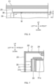
- Water-permeable porous body 35 is formed in a rectangular parallelepiped shape and is attached to a position on the left of magnet 34. An upper end of water-permeable porous body 35 is positioned lower than upper ends of the pair of elongate portions 31a1. Water-permeable porous body 35 is attached to the upper surface of left-side sliding door 30 (namely, the upper surface of upper stile 31a) to partially position inside left stile 31b. Because left stile 31b is in the tubular form being opened at the opposite ends as described above, a portion of water-permeable porous body 35 positioned inside left stile 31b extends downward and faces lower frame 22.
- Left-side sliding door 30 further includes packing 37, a pair of upper sealing members S2, and a pair of lower sealing members S3. Packing 37, the pair of upper sealing members S2, and the pair of lower sealing members S3 seal between left-side sliding door 30 and frame 20 in the state in which left-side sliding door 30 is closed.
- packing 37 is denoted by a two-dot-chain line.
- left-side sliding door 30 When left-side sliding door 30 is moved to the right, door rollers 33 climbs up from recessed portions 22b, and hence left-side sliding door 30 is elevated upward corresponding to the depths of recessed portions 22b.
- packing 37 departs away from left-side vertical frame 23
- the pair of upper sealing members S2 depart away from protruding portion 21a1 and auxiliary sealing member S1
- the pair of lower sealing members S3 depart away from lower frame 22.
- Left-side sliding door 30 is moved to the right along the pair of rails 22a while the narrowed gap between second water-permeable porous body 36 and heat-insulating porous body 25 is kept.
- right-side sliding door 40 in the closed state is opened, right-side sliding door 40 operates in a similar way to the above-described operation of left-side sliding door 30 except for that right-side sliding door 40 is moved in a direction opposite to the movement of left-side sliding door 30 (namely to the left).
- a flow path of the dew condensation water generating on upper frame 21 above left-side sliding door 30 in the closed state will be described below.
- the dew condensation water generates on upper frame 21 due to a temperature difference between the temperature in the storage chamber and the temperature of outside air.
- the dew condensation water generates on an inner surface of upper frame 21 and a surface of heat-insulating porous body 25.
- the dew condensation water having generated on upper frame 21 collects into a droplet and then falls down onto respective upper surfaces of second water-permeable porous body 36 and upper stile 31a.
- the dew condensation water having fallen down onto second water-permeable porous body 36 passes through second water-permeable porous body 36 and flows onto the upper surface of upper stile 31a. Furthermore, as described above, the upper surface of left-side sliding door 30 inclines from the upper side toward the lower side as a position gradually goes toward the left from the right in the closed state of left-side sliding door 30.
- the dew condensation water flowing to the left over the upper surface of upper stile 31a reaches water-permeable porous body 35.
- the dew condensation water having reached water-permeable porous body 35 passes through water-permeable porous body 35 and flows to the inside of left stile 31b. Because water-permeable porous body 35 has the continuous foam structure as described above, water-permeable porous body 35 acts as a resistance against a flow of the dew condensation water.
- second water-permeable porous body 36 approaches heat-insulating porous body 25. Accordingly, as illustrated in FIG. 6 , second water-permeable porous body 36 scrapes off a droplet W of the dew condensation water present on the surface of heat-insulating porous body 25.
- the dew condensation water can be prevented from falling down onto the sample or the like.
- right-side sliding door 40 is constituted to be symmetrical to left-side sliding door 30 in the left-right direction. Moreover, because recessed portion 22b on the right side, corresponding to right-side sliding door 40, is formed to be deeper than recessed portion 22b on left side, the upper surface of right-side sliding door 40 inclines from the upper side toward the lower side as a position gradually goes toward the right from the left in the closed state of right-side sliding door 40. Accordingly, as with the above-described dew condensation water falling down onto the upper surface of left-side sliding door 30, the dew condensation water falling down onto the upper surface of right-side sliding door 40 passes through water-permeable porous body 35 and flows toward lower frame 22 through the inside of the right stile.
- a size of the gap between second water-permeable porous body 36 and heat-insulating porous body 25 when left-side sliding door 30 is moved may be different from that between second water-permeable porous body 36 and heat-insulating porous body 25 when right-side sliding door 40 is moved.
- the gap between second water-permeable porous body 36 and heat-insulating porous body 25 may be set to be narrower for one of left-side sliding door 30 and right-side sliding door 40 on which the dew condensation water is more apt to generate. This feature enables second water-permeable porous body 36 to more easily scrape off the dew condensation water for the one of left-side sliding door 30 and right-side sliding door 40 on which the dew condensation water is more apt to generate.
- Heat-insulating porous body 25 may not always need to be attached to upper frame 21.
- second water-permeable porous body 36 is formed such that, when left-side sliding door 30 and right-side sliding door 40 are each moved, second water-permeable porous body 36 approaches a portion of upper frame 21, the portion being positioned to face second water-permeable porous body 36, and scrapes off the droplet of the dew condensation water.
- water-permeable porous body 35 has the L-like shape ( FIG. 2 ), it may have a linear shape as illustrated in FIG. 7 . In this case, water-permeable porous body 35 can be more easily manufactured. When water-permeable porous body 35 is formed in a flexible shape, water-permeable porous body 35 can be easily attached without bending the same in advance. Moreover, when the upper end of left stile 31b is at the same height as the upper surface of upper stile 31a as illustrated in FIG. 7 , water-permeable porous body 35 formed in the linear shape is disposed to overlap with the inside of left stile 31b and to face lower frame 22 without being partially disposed inside left stile 31b.
- left stile 31b serves as the drain channel through which the dew condensation water passes
- the drain channel may be further formed in the inside of right stile 31cl.
- right stile 31c is constituted in the form of a tube as with left stile 31b, and a porous body with water permeability may be attached to the upper surface of upper stile 31a to establish fluid communication with the inside of right stile 31c.
- the depths of two recessed portions 22b corresponding to left-side sliding door 30 may be set equal to each other such that the upper surface of left-side sliding door 30 does not incline in the closed state (namely, such that the upper surface of left-side sliding door 30 is substantially horizontal).
- the drain channel may not always need to be formed in the inside of left stile 31b and may be formed only in the inside of right stile 31c.
- the upper surface of left-side sliding door 30 may incline from the upper side toward the lower side as a position gradually goes toward the right from the left in the closed state of left-side sliding door 30.
- recessed portion 22b on the right side is formed to be deeper than recessed portion 22b on the left side.
- Each of left-side sliding door 30 and right-side sliding door 40 does not always need to include the pair of elongate portions 31a1.
- door rollers 33 are attached to lower stile 31d, they may be attached to upper stile 31a.
- left-side sliding door 30 and right-side sliding door 40 are each constituted as a suspended sliding door.
- Left-side sliding door 30 and right-side sliding door 40 may not always need to include door rollers 33.
- the positions at which door rollers 33 are attached may be adjusted to make each of left-side sliding door 30 and right-side sliding door 40 inclined such that a portion of the upper surface of the sliding door on a side nearer to the drain channel is positioned at a relatively low level even during the movement of the sliding door.
- the present disclosure can be widely applied to cold storages, such as a cold storage for pharmaceuticals, a cold storage for blood, and a constant temperature container.
Landscapes
- Engineering & Computer Science (AREA)
- Physics & Mathematics (AREA)
- Thermal Sciences (AREA)
- Mechanical Engineering (AREA)
- General Engineering & Computer Science (AREA)
- Chemical & Material Sciences (AREA)
- Combustion & Propulsion (AREA)
- Specific Sealing Or Ventilating Devices For Doors And Windows (AREA)
- Removal Of Water From Condensation And Defrosting (AREA)
Claims (6)
- Kühllager (1), mit:einem Kasten (10) mit einer Öffnung (H) an der Vorderseite;einem Rahmen (20), der die Öffnung begrenzt; undeiner Schiebetür (30, 40), die an dem Rahmen angebracht ist und in einem linkseitigen Endabschnitt und/oder einem rechtsseitigen Endabschnitt einen Ablaufkanal enthält, der vertikal verläuft;dadurch gekennzeichnet, dass ferner vorgesehen istein poröser Körper (35, 36) mit Wasserdurchlässigkeit, wobei der poröse Körper an einer oberen Fläche der Schiebetür derart angebracht ist, dass eine Fluidverbindung zu dem Ablaufkanal hergestellt ist.
- Kühllager nach Anspruch 1, wobei der poröse Körper ein Schaumstoff mit einer zusammenhängenden Schaumstruktur ist.
- Kühllager nach Anspruch 1 oder 2, wobei der poröse Körper derart angebracht ist, dass er sich von der oberen Fläche der Schiebetür in den Ablaufkanal erstreckt.
- Kühllager nach einem der Ansprüche 1 bis 3, wobei die Schiebetür zwei als Paar vorgesehene längliche Abschnitte (31a1) aufweist, die an einem oberen Ende der Schiebetür entsprechend an einer Vorderseite und einer Rückseite angeordnet sind und eine Rinne bilden.
- Kühllager nach einem der Ansprüche 1 bis 4, wobeidie Schiebetür eine Türrolle (33) aufweist,der Rahmen einen ausgesparten Abschnitt (22b) aufweist, in den die Türrolle fällt, wenn die Schiebetür geschlossen wird, und von welchem die Türrolle nach oben steigt, wenn die Schiebetür geöffnet wird, undder poröse Körper sich einem oberen Seitenabschnitt des Rahmens annähert, wenn die Schiebetür geöffnet wird.
- Kühllager nach einem der Ansprüche 1 bis 5, das ferner aufweist:
einen zweiten porösen Körper (25) mit Wärmeisolierung, wobei der zweite poröse Körper an dem Rahmen derart angebracht ist, dass er eine Lage hat, so dass er der oberen Fläche der Schiebetür im geschlossenen Zustand zugewandt ist.
Applications Claiming Priority (2)
| Application Number | Priority Date | Filing Date | Title |
|---|---|---|---|
| JP2021038276 | 2021-03-10 | ||
| PCT/JP2022/004482 WO2022190734A1 (ja) | 2021-03-10 | 2022-02-04 | 保冷庫 |
Publications (3)
| Publication Number | Publication Date |
|---|---|
| EP4276392A1 EP4276392A1 (de) | 2023-11-15 |
| EP4276392A4 EP4276392A4 (de) | 2024-07-03 |
| EP4276392B1 true EP4276392B1 (de) | 2025-04-16 |
Family
ID=83227866
Family Applications (1)
| Application Number | Title | Priority Date | Filing Date |
|---|---|---|---|
| EP22766699.7A Active EP4276392B1 (de) | 2021-03-10 | 2022-02-04 | Kühlbox |
Country Status (5)
| Country | Link |
|---|---|
| US (1) | US12313345B2 (de) |
| EP (1) | EP4276392B1 (de) |
| JP (1) | JP7489537B2 (de) |
| CN (1) | CN116888414B (de) |
| WO (1) | WO2022190734A1 (de) |
Families Citing this family (2)
| Publication number | Priority date | Publication date | Assignee | Title |
|---|---|---|---|---|
| EP4001808B1 (de) * | 2019-08-27 | 2023-10-25 | PHC Corporation | Kältegerät |
| CN112547139B (zh) * | 2021-02-24 | 2021-07-23 | 赛默飞世尔(上海)仪器有限公司 | 用于生物安全柜的反馈机构 |
Family Cites Families (14)
| Publication number | Priority date | Publication date | Assignee | Title |
|---|---|---|---|---|
| JPS5060830U (de) | 1973-09-28 | 1975-06-04 | ||
| JPS554463Y2 (de) | 1975-05-06 | 1980-02-01 | ||
| JP2691481B2 (ja) * | 1990-06-29 | 1997-12-17 | ホシザキ電機株式会社 | 貯蔵庫の結露水捕捉装置 |
| JP2589158Y2 (ja) * | 1992-08-20 | 1999-01-20 | ホシザキ電機株式会社 | 冷蔵ショーケースの引扉 |
| JP2994979B2 (ja) * | 1995-02-10 | 1999-12-27 | 三洋電機株式会社 | 冷却貯蔵庫 |
| JP4373519B2 (ja) | 1999-03-08 | 2009-11-25 | ホシザキ電機株式会社 | ショーケース等の上レール構造 |
| JP2009066296A (ja) | 2007-09-14 | 2009-04-02 | Hoshizaki Electric Co Ltd | ショーケースの扉構造 |
| KR101073061B1 (ko) * | 2008-10-02 | 2011-10-12 | 알루텍 (주) | 변형방지용 지지부재를 구비한 미서기 창호 |
| JP5448664B2 (ja) * | 2009-09-10 | 2014-03-19 | ホシザキ電機株式会社 | 冷却貯蔵庫の扉装置 |
| CN103519610A (zh) * | 2013-11-01 | 2014-01-22 | 合肥华凌股份有限公司 | 展示柜 |
| CA2851022A1 (en) * | 2014-05-01 | 2015-11-01 | Andersen Corporation | Draining sill and frame assembly incorporating the same |
| JP7186674B2 (ja) * | 2019-07-22 | 2022-12-09 | ホシザキ株式会社 | 貯蔵庫 |
| EP4001808B1 (de) | 2019-08-27 | 2023-10-25 | PHC Corporation | Kältegerät |
| JP7335497B2 (ja) | 2019-08-30 | 2023-08-30 | 横浜ゴム株式会社 | タイヤ用ゴム組成物 |
-
2022
- 2022-02-04 JP JP2023505222A patent/JP7489537B2/ja active Active
- 2022-02-04 CN CN202280013290.6A patent/CN116888414B/zh active Active
- 2022-02-04 WO PCT/JP2022/004482 patent/WO2022190734A1/ja not_active Ceased
- 2022-02-04 EP EP22766699.7A patent/EP4276392B1/de active Active
-
2023
- 2023-08-18 US US18/452,356 patent/US12313345B2/en active Active
Also Published As
| Publication number | Publication date |
|---|---|
| JP7489537B2 (ja) | 2024-05-23 |
| CN116888414A (zh) | 2023-10-13 |
| JPWO2022190734A1 (de) | 2022-09-15 |
| US20230392877A1 (en) | 2023-12-07 |
| EP4276392A4 (de) | 2024-07-03 |
| US12313345B2 (en) | 2025-05-27 |
| WO2022190734A1 (ja) | 2022-09-15 |
| EP4276392A1 (de) | 2023-11-15 |
| CN116888414B (zh) | 2026-04-21 |
Similar Documents
| Publication | Publication Date | Title |
|---|---|---|
| US12313345B2 (en) | Cold storage including a sliding door having a vertical drain | |
| JP5787454B2 (ja) | 自動ドア及び半自動ドア用窓装置 | |
| KR20030062307A (ko) | 하부틀 상면이 플랫한 옥외용 샤시 구조 | |
| JP6557614B2 (ja) | 建具 | |
| KR101674560B1 (ko) | 밀폐장치 및 이를 포함하는 도어 | |
| US9433325B2 (en) | Sliding shower door guide and drain assembly | |
| JP4032423B2 (ja) | 下枠フラットサッシの下枠断熱構造 | |
| KR102458788B1 (ko) | 미서기창 구조 | |
| JP2016131823A (ja) | リーチイン型のショーケース | |
| CN108266107B (zh) | 一种防雨通气窗及防雨通气结构 | |
| KR200401750Y1 (ko) | 창호용 필링피스 | |
| KR101311359B1 (ko) | 미닫이 창호 프레임의 밀폐구 | |
| JP4600157B2 (ja) | サッシの排水具 | |
| JP5013970B2 (ja) | 自動販売機 | |
| KR20170031540A (ko) | 기밀성능과 수밀성능이 향상된 미서기창 | |
| JP7425671B2 (ja) | 建具 | |
| KR101210806B1 (ko) | 냉기손실이 없는 선반구조 | |
| JP6093160B2 (ja) | 開口部装置 | |
| JP4467328B2 (ja) | 引戸装置の下隅角部のシール装置 | |
| GB2351229A (en) | Shower door seal | |
| KR20200009284A (ko) | 벨트창호 | |
| RU2003103595A (ru) | Установка непрерывного действия для поверхностной обработки лент в емкости | |
| JP4975299B2 (ja) | 引違いサッシ | |
| JP2020176445A (ja) | 建具 | |
| US702588A (en) | Window frame and sash. |
Legal Events
| Date | Code | Title | Description |
|---|---|---|---|
| STAA | Information on the status of an ep patent application or granted ep patent |
Free format text: STATUS: THE INTERNATIONAL PUBLICATION HAS BEEN MADE |
|
| PUAI | Public reference made under article 153(3) epc to a published international application that has entered the european phase |
Free format text: ORIGINAL CODE: 0009012 |
|
| STAA | Information on the status of an ep patent application or granted ep patent |
Free format text: STATUS: REQUEST FOR EXAMINATION WAS MADE |
|
| 17P | Request for examination filed |
Effective date: 20230809 |
|
| AK | Designated contracting states |
Kind code of ref document: A1 Designated state(s): AL AT BE BG CH CY CZ DE DK EE ES FI FR GB GR HR HU IE IS IT LI LT LU LV MC MK MT NL NO PL PT RO RS SE SI SK SM TR |
|
| DAV | Request for validation of the european patent (deleted) | ||
| DAX | Request for extension of the european patent (deleted) | ||
| A4 | Supplementary search report drawn up and despatched |
Effective date: 20240605 |
|
| RIC1 | Information provided on ipc code assigned before grant |
Ipc: F25D 23/02 20060101ALI20240529BHEP Ipc: A47F 3/04 20060101ALI20240529BHEP Ipc: F25D 21/14 20060101AFI20240529BHEP |
|
| GRAP | Despatch of communication of intention to grant a patent |
Free format text: ORIGINAL CODE: EPIDOSNIGR1 |
|
| STAA | Information on the status of an ep patent application or granted ep patent |
Free format text: STATUS: GRANT OF PATENT IS INTENDED |
|
| RIC1 | Information provided on ipc code assigned before grant |
Ipc: F25D 23/02 20060101ALI20241029BHEP Ipc: A47F 3/04 20060101ALI20241029BHEP Ipc: F25D 21/14 20060101AFI20241029BHEP |
|
| INTG | Intention to grant announced |
Effective date: 20241203 |
|
| RAP3 | Party data changed (applicant data changed or rights of an application transferred) |
Owner name: PHC HOLDINGS CORPORATION |
|
| GRAS | Grant fee paid |
Free format text: ORIGINAL CODE: EPIDOSNIGR3 |
|
| GRAA | (expected) grant |
Free format text: ORIGINAL CODE: 0009210 |
|
| STAA | Information on the status of an ep patent application or granted ep patent |
Free format text: STATUS: THE PATENT HAS BEEN GRANTED |
|
| AK | Designated contracting states |
Kind code of ref document: B1 Designated state(s): AL AT BE BG CH CY CZ DE DK EE ES FI FR GB GR HR HU IE IS IT LI LT LU LV MC MK MT NL NO PL PT RO RS SE SI SK SM TR |
|
| REG | Reference to a national code |
Ref country code: GB Ref legal event code: FG4D |
|
| REG | Reference to a national code |
Ref country code: CH Ref legal event code: EP |
|
| REG | Reference to a national code |
Ref country code: IE Ref legal event code: FG4D |
|
| REG | Reference to a national code |
Ref country code: DE Ref legal event code: R096 Ref document number: 602022013310 Country of ref document: DE |
|
| REG | Reference to a national code |
Ref country code: NL Ref legal event code: MP Effective date: 20250416 |
|
| PG25 | Lapsed in a contracting state [announced via postgrant information from national office to epo] |
Ref country code: NL Free format text: LAPSE BECAUSE OF FAILURE TO SUBMIT A TRANSLATION OF THE DESCRIPTION OR TO PAY THE FEE WITHIN THE PRESCRIBED TIME-LIMIT Effective date: 20250416 |
|
| REG | Reference to a national code |
Ref country code: AT Ref legal event code: MK05 Ref document number: 1785927 Country of ref document: AT Kind code of ref document: T Effective date: 20250416 |
|
| PG25 | Lapsed in a contracting state [announced via postgrant information from national office to epo] |
Ref country code: PT Free format text: LAPSE BECAUSE OF FAILURE TO SUBMIT A TRANSLATION OF THE DESCRIPTION OR TO PAY THE FEE WITHIN THE PRESCRIBED TIME-LIMIT Effective date: 20250818 Ref country code: FI Free format text: LAPSE BECAUSE OF FAILURE TO SUBMIT A TRANSLATION OF THE DESCRIPTION OR TO PAY THE FEE WITHIN THE PRESCRIBED TIME-LIMIT Effective date: 20250416 Ref country code: ES Free format text: LAPSE BECAUSE OF FAILURE TO SUBMIT A TRANSLATION OF THE DESCRIPTION OR TO PAY THE FEE WITHIN THE PRESCRIBED TIME-LIMIT Effective date: 20250416 |
|
| REG | Reference to a national code |
Ref country code: LT Ref legal event code: MG9D |
|
| PG25 | Lapsed in a contracting state [announced via postgrant information from national office to epo] |
Ref country code: NO Free format text: LAPSE BECAUSE OF FAILURE TO SUBMIT A TRANSLATION OF THE DESCRIPTION OR TO PAY THE FEE WITHIN THE PRESCRIBED TIME-LIMIT Effective date: 20250716 Ref country code: GR Free format text: LAPSE BECAUSE OF FAILURE TO SUBMIT A TRANSLATION OF THE DESCRIPTION OR TO PAY THE FEE WITHIN THE PRESCRIBED TIME-LIMIT Effective date: 20250717 |
|
| PG25 | Lapsed in a contracting state [announced via postgrant information from national office to epo] |
Ref country code: PL Free format text: LAPSE BECAUSE OF FAILURE TO SUBMIT A TRANSLATION OF THE DESCRIPTION OR TO PAY THE FEE WITHIN THE PRESCRIBED TIME-LIMIT Effective date: 20250416 |
|
| PG25 | Lapsed in a contracting state [announced via postgrant information from national office to epo] |
Ref country code: BG Free format text: LAPSE BECAUSE OF FAILURE TO SUBMIT A TRANSLATION OF THE DESCRIPTION OR TO PAY THE FEE WITHIN THE PRESCRIBED TIME-LIMIT Effective date: 20250416 |
|
| PG25 | Lapsed in a contracting state [announced via postgrant information from national office to epo] |
Ref country code: HR Free format text: LAPSE BECAUSE OF FAILURE TO SUBMIT A TRANSLATION OF THE DESCRIPTION OR TO PAY THE FEE WITHIN THE PRESCRIBED TIME-LIMIT Effective date: 20250416 |
|
| PG25 | Lapsed in a contracting state [announced via postgrant information from national office to epo] |
Ref country code: AT Free format text: LAPSE BECAUSE OF FAILURE TO SUBMIT A TRANSLATION OF THE DESCRIPTION OR TO PAY THE FEE WITHIN THE PRESCRIBED TIME-LIMIT Effective date: 20250416 |
|
| PG25 | Lapsed in a contracting state [announced via postgrant information from national office to epo] |
Ref country code: RS Free format text: LAPSE BECAUSE OF FAILURE TO SUBMIT A TRANSLATION OF THE DESCRIPTION OR TO PAY THE FEE WITHIN THE PRESCRIBED TIME-LIMIT Effective date: 20250716 |
|
| PG25 | Lapsed in a contracting state [announced via postgrant information from national office to epo] |
Ref country code: IS Free format text: LAPSE BECAUSE OF FAILURE TO SUBMIT A TRANSLATION OF THE DESCRIPTION OR TO PAY THE FEE WITHIN THE PRESCRIBED TIME-LIMIT Effective date: 20250816 |
|
| PG25 | Lapsed in a contracting state [announced via postgrant information from national office to epo] |
Ref country code: LV Free format text: LAPSE BECAUSE OF FAILURE TO SUBMIT A TRANSLATION OF THE DESCRIPTION OR TO PAY THE FEE WITHIN THE PRESCRIBED TIME-LIMIT Effective date: 20250416 |
|
| PG25 | Lapsed in a contracting state [announced via postgrant information from national office to epo] |
Ref country code: DK Free format text: LAPSE BECAUSE OF FAILURE TO SUBMIT A TRANSLATION OF THE DESCRIPTION OR TO PAY THE FEE WITHIN THE PRESCRIBED TIME-LIMIT Effective date: 20250416 Ref country code: SM Free format text: LAPSE BECAUSE OF FAILURE TO SUBMIT A TRANSLATION OF THE DESCRIPTION OR TO PAY THE FEE WITHIN THE PRESCRIBED TIME-LIMIT Effective date: 20250416 |
|
| REG | Reference to a national code |
Ref country code: DE Ref legal event code: R097 Ref document number: 602022013310 Country of ref document: DE |
|
| PG25 | Lapsed in a contracting state [announced via postgrant information from national office to epo] |
Ref country code: CZ Free format text: LAPSE BECAUSE OF FAILURE TO SUBMIT A TRANSLATION OF THE DESCRIPTION OR TO PAY THE FEE WITHIN THE PRESCRIBED TIME-LIMIT Effective date: 20250416 |
|
| PG25 | Lapsed in a contracting state [announced via postgrant information from national office to epo] |
Ref country code: EE Free format text: LAPSE BECAUSE OF FAILURE TO SUBMIT A TRANSLATION OF THE DESCRIPTION OR TO PAY THE FEE WITHIN THE PRESCRIBED TIME-LIMIT Effective date: 20250416 |
|
| PG25 | Lapsed in a contracting state [announced via postgrant information from national office to epo] |
Ref country code: SK Free format text: LAPSE BECAUSE OF FAILURE TO SUBMIT A TRANSLATION OF THE DESCRIPTION OR TO PAY THE FEE WITHIN THE PRESCRIBED TIME-LIMIT Effective date: 20250416 |
|
| PG25 | Lapsed in a contracting state [announced via postgrant information from national office to epo] |
Ref country code: IT Free format text: LAPSE BECAUSE OF FAILURE TO SUBMIT A TRANSLATION OF THE DESCRIPTION OR TO PAY THE FEE WITHIN THE PRESCRIBED TIME-LIMIT Effective date: 20250416 |
|
| PLBE | No opposition filed within time limit |
Free format text: ORIGINAL CODE: 0009261 |
|
| STAA | Information on the status of an ep patent application or granted ep patent |
Free format text: STATUS: NO OPPOSITION FILED WITHIN TIME LIMIT |
|
| REG | Reference to a national code |
Ref country code: CH Ref legal event code: L10 Free format text: ST27 STATUS EVENT CODE: U-0-0-L10-L00 (AS PROVIDED BY THE NATIONAL OFFICE) Effective date: 20260225 |
|
| 26N | No opposition filed |
Effective date: 20260119 |
|
| PGFP | Annual fee paid to national office [announced via postgrant information from national office to epo] |
Ref country code: GB Payment date: 20260227 Year of fee payment: 5 |
|
| PGFP | Annual fee paid to national office [announced via postgrant information from national office to epo] |
Ref country code: DE Payment date: 20260227 Year of fee payment: 5 |