EP4271925B1 - Wand und rohrdurchführung für ein rohr an dieser wand - Google Patents
Wand und rohrdurchführung für ein rohr an dieser wand Download PDFInfo
- Publication number
- EP4271925B1 EP4271925B1 EP21854803.0A EP21854803A EP4271925B1 EP 4271925 B1 EP4271925 B1 EP 4271925B1 EP 21854803 A EP21854803 A EP 21854803A EP 4271925 B1 EP4271925 B1 EP 4271925B1
- Authority
- EP
- European Patent Office
- Prior art keywords
- pipe
- flange
- wall
- feedthrough
- pipe feedthrough
- Prior art date
- Legal status (The legal status is an assumption and is not a legal conclusion. Google has not performed a legal analysis and makes no representation as to the accuracy of the status listed.)
- Active
Links
Images

Classifications
-
- F—MECHANICAL ENGINEERING; LIGHTING; HEATING; WEAPONS; BLASTING
- F16—ENGINEERING ELEMENTS AND UNITS; GENERAL MEASURES FOR PRODUCING AND MAINTAINING EFFECTIVE FUNCTIONING OF MACHINES OR INSTALLATIONS; THERMAL INSULATION IN GENERAL
- F16L—PIPES; JOINTS OR FITTINGS FOR PIPES; SUPPORTS FOR PIPES, CABLES OR PROTECTIVE TUBING; MEANS FOR THERMAL INSULATION IN GENERAL
- F16L5/00—Devices for use where pipes, cables or protective tubing pass through walls or partitions
- F16L5/02—Sealing
- F16L5/10—Sealing by using sealing rings or sleeves only
Definitions
- the invention relates to a wall and a pipe duct for a pipe on a wall, in particular an external wall, with a plastic body, which plastic body has a pipe socket for the passage of the pipe and a circumferential flange on the pipe socket, and with a flexible sleeve which is firmly connected to the plastic body and projects laterally away from it.
- a pipe penetration In order to seal the pipe transition into a wall or into the floor against liquids and moisture, a pipe penetration is known (EP0300963B1 ), which encloses the pipe with a pipe socket in a liquid-tight manner and also connects it to the wall and/or floor in a liquid-tight manner with a liquid-tight foil sleeve.
- pipe penetrations are used for drainage and are not used on walls, as they cannot withstand weather-related adversities.
- a facade composite with a breakthrough is known through which a load-bearing element is anchored in a load-bearing wall.
- a cylindrical hollow body made of a reinforcing mesh is inserted into the breakthrough up to a fold, folded over at this fold and glued.
- a pipe socket is then attached to the breakthrough and glued to the cylindrical hollow body.
- the DE19544957A1 and the WO2019/211467A1 reveal sleeves that can be pushed onto a pipe and attached to a wall.
- the invention therefore has the task of creating a pipe duct that can be used stably on an external wall.
- the invention solves the problem by the features of claim 1.
- the pipe duct can also be installed securely on an external wall, as the flexibility and high tensile strength of the reinforcing mesh allow a particularly stable connection to the external wall.
- the expansion of the sleeve can remain low according to the invention, which prevents cracks in the external wall - and thus reduces the risk of moisture and liquids entering the wall. This creates a stable pipe duct that can withstand adverse environmental influences, such as those found on an external wall.
- a glass fiber mesh, polyester mesh, etc. can be used as a reinforcing mesh in grid form.
- the reinforcing mesh can be coated with a plastic finish.
- the plastic body is preferably made of a PVC material, although a PP material is also possible.
- the pipe socket can have an internal seal, in particular a lip seal, in order to additionally enable a stable, liquid-tight seal with the pipe to be passed through.
- the installation of the pipe socket can be made easier - this is particularly true because pipes for water drainage usually penetrate the outer wall at an angle. It is therefore not necessary to tilt the pipe socket relative to the usually vertical outer wall in order to be able to pass the pipe through at an angle or to accommodate it in the installation position.
- this angle ⁇ is in the range of 75 to less than 90 degrees, essentially any standardized inclination of the installed pipes can be accommodated by the pipe socket. 87 degrees can prove to be particularly suitable in this regard.
- the design of the pipe penetration can be further simplified if the reinforcing mesh is welded to the flange.
- the reinforcing mesh is welded to the flange at its flange front.
- the strength of the welded connection can be further improved if the flange has a connection area with the welded reinforcing fabric, wherein in this connection area the surface has an increased average roughness compared to an adjoining surface of the pipe duct, in particular the flange.
- a surface in the connection area can be created by roughening, for example with quartz sand, etc.
- the reinforcing mesh is embedded in the plastic body. This can also strengthen the bond between the reinforcing mesh and the plastic body, thereby ensuring increased stability even in the most extreme weather conditions.
- the installation and especially the embedding of the pipe penetration into a coating of the wall can be further facilitated if on the front side of the Pipe feedthrough, one pipe end of the pipe socket protrudes from the flange and thus forms a plastering edge.
- the plastering edge makes it easy to check the position of the pipe feedthrough on the wall - which can also make handling the pipe feedthrough easier.
- the pipe duct By attaching the reinforcing mesh in the connection area of the pipe end with the flange embedded in the plastic body, the pipe duct can be firmly embedded in a wall coating up to the plaster edge.
- the reinforcing mesh runs over the flange on the front side of the pipe penetration to facilitate embedding the pipe penetration in a coating of the wall.
- the handling of the pipe penetration is made even easier if the flange has a flange thickness of 2 to 10 mm (millimeters). This is even more so if the flange has a flange width of 25 to 35 mm.
- the flange width is preferably 30 mm, which can provide a sufficient connection surface for the reinforcing mesh, for example.
- the pipe socket has a length of up to 50 mm. It can already prove sufficient for versatile use of the pipe feedthrough if the pipe socket has an inner diameter that is designed to pass through a pipe with a nominal width of at least DN 50, in particular at least DN 100.
- the pipe duct can be placed on an external wall for easier handling if the flange front and plaster edge are in normal alignment with each other.
- the projection of the pipe end in millimeters together with the flange thickness in millimeters is in the range of 5 to 11 mm, in particular either 6 mm or 9 mm, which can ensure easy handling of the pipe duct when plastering a wide variety of coating compounds.
- the pipe duct is preferably used on a wall, in particular an external wall, with an external coating compound.
- the reinforcing fabric of the pipe duct is embedded in the coating compound, which is in particular a plaster compound and/or filler compound.
- the wall can have a pipe for draining a roof, in particular a flat roof.
- the pipe penetrating the pipe duct ensures a particularly moisture- and liquid-tight seal of the outer wall in the area of the pipe opening.
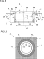
- FIG. 3 a wall of a building (not shown in detail) designed as an outer wall 1 is shown, on which an outer coating compound 2 is provided.
- a pipe 3 leads through this outer wall 1 for draining a flat roof 4, which has thermal insulation 4a.
- the pipe 3 protrudes from the outer wall 1 on the outside of the building (not shown in detail).
- the pipe duct 5 is provided, with its front side 5a facing the outside of the outer wall 1.
- the pipe duct 5 seals the outer wall 1 against the ingress of moisture and/or water.
- the pipe duct 5 shown in more detail has a plastic body 6 made of PVC and a sleeve 7.
- the plastic body 6 has a pipe socket 8 and a flange 9 surrounding the pipe socket 8.
- the pipe 3 leads through the pipe socket 8, as in Fig. 1 can be seen.
- the cuff 7 is firmly connected to the plastic body 6 and protrudes laterally from this plastic body 6.
- the sleeve 7 is flexible. This is achieved in that, according to the invention, the sleeve 7 is formed from a reinforcing fabric 17 in grid form, namely glass fiber grid fabric, as is shown in the Fig. 2 can be recognized in detail. This allows the pipe duct 5 to be firmly embedded in the coating compound 2, namely a plaster compound 2a, of the outer wall 1. Weather-related adversities therefore do not endanger the moisture- and liquid-tight seal between the pipe duct 5 and the outer wall 1.
- An inner seal 10 ensures a stable and tight seal between pipe 3 and plastic body 6.
- This inner seal 10 is designed as a lip seal 10a, which is inserted in a form-fitting manner in an inner recess 11 of the pipe socket 8 and is preferably located in the area of the second pipe end 8b.
- the second pipe end 8b protrudes from the flange back 9b by several times the projection 12 of the pipe end 8a.
- the pipe 3 which runs through the outer wall 1 at an incline of 3 degrees according to the standard, is accommodated coaxially by the pipe duct 5 without jamming.
- the longitudinal axis L of the pipe socket 8 is inclined to the transverse axis Q through the flange 9 at an angle ⁇ ⁇ 90 degrees, namely by exactly 87 degrees.
- the angle ⁇ is therefore in the range from 75 to less than 90 degrees.
- the reinforcing fabric 17 is attached in the connection area 5b of the pipe end 8a of the pipe socket 8 with the flange 9 embedded in the plastic body 6.
- one end 17a of the reinforcing fabric 17 is provided inside the plastic body 6.
- the reinforcing mesh 17 is welded to the flange 9, as shown in Fig. 2 hatched over the reinforcing fabric 17.
- the welding can be carried out, for example, by melting the flange 9 with the possible addition of an additional material, for example polymer, preferably from which the plastic body is made.
- thermal welding can be suitable for this.
- the reinforcing fabric 17 is coated with a plastic finish.
- this plastic finish and the plastic body 6 are made of the same polymer, which facilitates welding.
- the flange 9 has a connection area 18 with the welded reinforcement fabric 17 on the front side 5a of the pipe duct 5 or thus on its flange front 5a.
- This connection area 18 extends over the entire flange front 9a, but a partial area of it is also conceivable.
- the surface Ov of the flange 9 in this connection area 18 is roughened, which ensures a stable, material-locking connection with the reinforcement fabric 17.
- This roughening which can be carried out for example by sand/shot blasting, perforating etc., can be seen in that the surface Ov in this connection area 18 is rougher and thus has an increased average roughness Ra in comparison with an adjoining surface O of the flange 9.
- the Fig. 1 It can be seen that the pipe socket 8 protrudes from the flange 9 on the front side 5a of the pipe duct 5 - namely with one pipe end 8a of two pipe ends 8a, 8b.
- This pipe end 8a forms a plastering edge 13 through this projection 12, as shown in the Fig. 3 to recognize - the plaster compound 2a is flush with the pipe end 8a.
- the pipe end 8a is therefore located on the front side 5a of the pipe duct 5.
- the pipe end 8a is visible on the wall.
- the flange front 9a and the plastering edge 13 are in normal alignment with each other, which ensures easy processing of the pipe duct 5 on the outer wall 1.
- the projection 12 of the plastering edge 13 is preferably 9 mm or 6 mm less than the flange thickness d in millimeters.
- the reinforcing fabric 17 runs over the flange 9 on the front side 5a of the pipe duct 5, which also ensures the adhesion of a coating compound 2 in the area of the flange 9.
- the flange 9 has a flange thickness of 2 to 10 mm and a flange width b of 30 mm.
- the pipe socket 8 has a length l of 37 mm, with the pipe end 8a of the pipe socket 8 projecting seven millimeters beyond the flange 9. With a flange thickness of 2 mm, the second pipe end 8b of the pipe socket 8 therefore projects 28 mm beyond the flange back 9b.
- the pipe socket 8 with its inner diameter di is designed for a pipe 3 with a nominal diameter of DN 100.
Landscapes
- Engineering & Computer Science (AREA)
- General Engineering & Computer Science (AREA)
- Mechanical Engineering (AREA)
- Rigid Pipes And Flexible Pipes (AREA)
- Building Environments (AREA)
Applications Claiming Priority (2)
| Application Number | Priority Date | Filing Date | Title |
|---|---|---|---|
| AT603812020 | 2020-12-30 | ||
| PCT/AT2021/060497 WO2022140815A1 (de) | 2020-12-30 | 2021-12-30 | Wand und rohrdurchführung für ein rohr an dieser wand |
Publications (3)
| Publication Number | Publication Date |
|---|---|
| EP4271925A1 EP4271925A1 (de) | 2023-11-08 |
| EP4271925C0 EP4271925C0 (de) | 2025-02-19 |
| EP4271925B1 true EP4271925B1 (de) | 2025-02-19 |
Family
ID=80222280
Family Applications (1)
| Application Number | Title | Priority Date | Filing Date |
|---|---|---|---|
| EP21854803.0A Active EP4271925B1 (de) | 2020-12-30 | 2021-12-30 | Wand und rohrdurchführung für ein rohr an dieser wand |
Country Status (3)
| Country | Link |
|---|---|
| EP (1) | EP4271925B1 (pl) |
| PL (1) | PL4271925T3 (pl) |
| WO (1) | WO2022140815A1 (pl) |
Family Cites Families (4)
| Publication number | Priority date | Publication date | Assignee | Title |
|---|---|---|---|---|
| CH673866A5 (pl) | 1987-07-24 | 1990-04-12 | Geberit Ag | |
| DE19544957A1 (de) * | 1995-12-02 | 1997-06-05 | Gefinex Jackon Gmbh | Dichtmanschette |
| DE202018001460U1 (de) * | 2018-03-19 | 2018-04-12 | Claus Cichos | Gedämmter Fassadenverbund mit Durchbrüchen |
| EP3735548B1 (de) * | 2018-05-04 | 2021-08-04 | Sopro Bauchemie GmbH | Dichtmanschette für verbundabdichtungen |
-
2021
- 2021-12-30 WO PCT/AT2021/060497 patent/WO2022140815A1/de not_active Ceased
- 2021-12-30 EP EP21854803.0A patent/EP4271925B1/de active Active
- 2021-12-30 PL PL21854803.0T patent/PL4271925T3/pl unknown
Also Published As
| Publication number | Publication date |
|---|---|
| PL4271925T3 (pl) | 2025-06-23 |
| WO2022140815A1 (de) | 2022-07-07 |
| EP4271925C0 (de) | 2025-02-19 |
| EP4271925A1 (de) | 2023-11-08 |
Similar Documents
| Publication | Publication Date | Title |
|---|---|---|
| DE2629214A1 (de) | Verfahren und mittel zum auskleiden von rohrleitungen | |
| EP0532459B1 (de) | Muffe zum Verbinden zweier Kunststoffrohre. | |
| EP1479838B1 (de) | Kunststoffrinne | |
| CH492839A (de) | Satz von Teilen zur Bildung einer Erd- und Oberflächen-Entwässerungsanlage | |
| DE2615428A1 (de) | Rohrdurchfuehrung | |
| EP4271925B1 (de) | Wand und rohrdurchführung für ein rohr an dieser wand | |
| AT524281B1 (de) | Rinnenkörper, Verbindungsvorrichtung, Stirnwand, Entwässerungsrinne, Anordnung und Verfahren | |
| DE102009037042A1 (de) | Schacht, insbesondere Kontroll- und Spül-Schacht für Abwasser mit einem Fließ-Gerinne und Platte für ein Fließ-Gerinne | |
| DE1759682A1 (de) | Einlaufschacht und Schachtboden aus Kunststoff | |
| DE9416411U1 (de) | Rohr, insbesondere Kunststoffrohr, und Rohrverbindung aus solchen Rohren | |
| DE4040495C2 (pl) | ||
| EP0405520B1 (de) | Verfahren zur Herstellung von Schächten | |
| DE202005007835U1 (de) | Rohr | |
| EP3848512B1 (de) | Verfahren zum erstellen eines gründungselementes im boden und gründungselement | |
| DE19745599C2 (de) | Verbundrohr und Verfahren zu dessen Herstellung | |
| DE2553388A1 (de) | Vorgefertigter kanalisationsschacht mit rohranschlusstuecken | |
| AT520104B1 (de) | Lichtschachtaufstockelement und Verfahren zur druckwasserdichten Montage eines Lichtschachtaufstockelements | |
| DE202010003282U1 (de) | Vorrichtung zum Verbinden eines Metallrohres mit einem Kunststoffrohr | |
| DE202009016484U1 (de) | Hülsenanker zur Anordnung in einem Betonteil | |
| DE202007005696U1 (de) | Rohrförmiges Bauelement zur Herstellung von Leitungen, Schächten, Formstücken u.dgl. | |
| DE4443983C2 (de) | Schachtanordnung | |
| EP1591712A2 (de) | Bausatz für eine Rohr-Verbindung und dessen Verwendung | |
| DD296133A5 (de) | Verfahren zur herstellung von schaechten | |
| DE102016103275A1 (de) | Dichtung einer Entwässerungsrinne | |
| EP3865750A1 (de) | Gebäudeeinführungsvorrichtung |
Legal Events
| Date | Code | Title | Description |
|---|---|---|---|
| STAA | Information on the status of an ep patent application or granted ep patent |
Free format text: STATUS: UNKNOWN |
|
| STAA | Information on the status of an ep patent application or granted ep patent |
Free format text: STATUS: THE INTERNATIONAL PUBLICATION HAS BEEN MADE |
|
| PUAI | Public reference made under article 153(3) epc to a published international application that has entered the european phase |
Free format text: ORIGINAL CODE: 0009012 |
|
| STAA | Information on the status of an ep patent application or granted ep patent |
Free format text: STATUS: REQUEST FOR EXAMINATION WAS MADE |
|
| 17P | Request for examination filed |
Effective date: 20230725 |
|
| AK | Designated contracting states |
Kind code of ref document: A1 Designated state(s): AL AT BE BG CH CY CZ DE DK EE ES FI FR GB GR HR HU IE IS IT LI LT LU LV MC MK MT NL NO PL PT RO RS SE SI SK SM TR |
|
| RAP1 | Party data changed (applicant data changed or rights of an application transferred) |
Owner name: KIRCHHOFER, THOMAS Owner name: SCHOERFLINGER, ALEXANDER |
|
| RIN1 | Information on inventor provided before grant (corrected) |
Inventor name: SCHOERFLINGER, ALEXANDER |
|
| RIN1 | Information on inventor provided before grant (corrected) |
Inventor name: KIRCHHOFER, THOMAS Inventor name: SCHOERFLINGER, ALEXANDER |
|
| DAV | Request for validation of the european patent (deleted) | ||
| GRAP | Despatch of communication of intention to grant a patent |
Free format text: ORIGINAL CODE: EPIDOSNIGR1 |
|
| STAA | Information on the status of an ep patent application or granted ep patent |
Free format text: STATUS: GRANT OF PATENT IS INTENDED |
|
| INTG | Intention to grant announced |
Effective date: 20240904 |
|
| GRAS | Grant fee paid |
Free format text: ORIGINAL CODE: EPIDOSNIGR3 |
|
| GRAA | (expected) grant |
Free format text: ORIGINAL CODE: 0009210 |
|
| STAA | Information on the status of an ep patent application or granted ep patent |
Free format text: STATUS: THE PATENT HAS BEEN GRANTED |
|
| RAP3 | Party data changed (applicant data changed or rights of an application transferred) |
Owner name: KIRCHHOFER, THOMAS Owner name: SCHOERFLINGER, ALEXANDER |
|
| RIN1 | Information on inventor provided before grant (corrected) |
Inventor name: KIRCHHOFER, THOMAS Inventor name: SCHOERFLINGER, ALEXANDER |
|
| AK | Designated contracting states |
Kind code of ref document: B1 Designated state(s): AL AT BE BG CH CY CZ DE DK EE ES FI FR GB GR HR HU IE IS IT LI LT LU LV MC MK MT NL NO PL PT RO RS SE SI SK SM TR |
|
| REG | Reference to a national code |
Ref country code: GB Ref legal event code: FG4D Free format text: NOT ENGLISH |
|
| REG | Reference to a national code |
Ref country code: CH Ref legal event code: EP |
|
| REG | Reference to a national code |
Ref country code: IE Ref legal event code: FG4D Free format text: LANGUAGE OF EP DOCUMENT: GERMAN |
|
| REG | Reference to a national code |
Ref country code: DE Ref legal event code: R096 Ref document number: 502021006732 Country of ref document: DE |
|
| U01 | Request for unitary effect filed |
Effective date: 20250319 |
|
| U07 | Unitary effect registered |
Designated state(s): AT BE BG DE DK EE FI FR IT LT LU LV MT NL PT RO SE SI Effective date: 20250324 |
|
| PG25 | Lapsed in a contracting state [announced via postgrant information from national office to epo] |
Ref country code: RS Free format text: LAPSE BECAUSE OF FAILURE TO SUBMIT A TRANSLATION OF THE DESCRIPTION OR TO PAY THE FEE WITHIN THE PRESCRIBED TIME-LIMIT Effective date: 20250519 |
|
| PG25 | Lapsed in a contracting state [announced via postgrant information from national office to epo] |
Ref country code: ES Free format text: LAPSE BECAUSE OF FAILURE TO SUBMIT A TRANSLATION OF THE DESCRIPTION OR TO PAY THE FEE WITHIN THE PRESCRIBED TIME-LIMIT Effective date: 20250219 |
|
| PG25 | Lapsed in a contracting state [announced via postgrant information from national office to epo] |
Ref country code: IS Free format text: LAPSE BECAUSE OF FAILURE TO SUBMIT A TRANSLATION OF THE DESCRIPTION OR TO PAY THE FEE WITHIN THE PRESCRIBED TIME-LIMIT Effective date: 20250619 Ref country code: NO Free format text: LAPSE BECAUSE OF FAILURE TO SUBMIT A TRANSLATION OF THE DESCRIPTION OR TO PAY THE FEE WITHIN THE PRESCRIBED TIME-LIMIT Effective date: 20250519 |
|
| PG25 | Lapsed in a contracting state [announced via postgrant information from national office to epo] |
Ref country code: HR Free format text: LAPSE BECAUSE OF FAILURE TO SUBMIT A TRANSLATION OF THE DESCRIPTION OR TO PAY THE FEE WITHIN THE PRESCRIBED TIME-LIMIT Effective date: 20250219 |
|
| REG | Reference to a national code |
Ref country code: SK Ref legal event code: T3 Ref document number: E 46385 Country of ref document: SK |
|
| PG25 | Lapsed in a contracting state [announced via postgrant information from national office to epo] |
Ref country code: GR Free format text: LAPSE BECAUSE OF FAILURE TO SUBMIT A TRANSLATION OF THE DESCRIPTION OR TO PAY THE FEE WITHIN THE PRESCRIBED TIME-LIMIT Effective date: 20250520 |
|
| PG25 | Lapsed in a contracting state [announced via postgrant information from national office to epo] |
Ref country code: SM Free format text: LAPSE BECAUSE OF FAILURE TO SUBMIT A TRANSLATION OF THE DESCRIPTION OR TO PAY THE FEE WITHIN THE PRESCRIBED TIME-LIMIT Effective date: 20250219 |
|
| PLBE | No opposition filed within time limit |
Free format text: ORIGINAL CODE: 0009261 |
|
| STAA | Information on the status of an ep patent application or granted ep patent |
Free format text: STATUS: NO OPPOSITION FILED WITHIN TIME LIMIT |
|
| PGFP | Annual fee paid to national office [announced via postgrant information from national office to epo] |
Ref country code: CZ Payment date: 20251217 Year of fee payment: 5 |
|
| PGFP | Annual fee paid to national office [announced via postgrant information from national office to epo] |
Ref country code: PL Payment date: 20251022 Year of fee payment: 5 |
|
| PGFP | Annual fee paid to national office [announced via postgrant information from national office to epo] |
Ref country code: SK Payment date: 20251229 Year of fee payment: 5 |
|
| 26N | No opposition filed |
Effective date: 20251120 |
|
| U20 | Renewal fee for the european patent with unitary effect paid |
Year of fee payment: 5 Effective date: 20251222 |