EP4271925B1 - Wall and pipe feedthrough for a pipe on said wall - Google Patents
Wall and pipe feedthrough for a pipe on said wall Download PDFInfo
- Publication number
- EP4271925B1 EP4271925B1 EP21854803.0A EP21854803A EP4271925B1 EP 4271925 B1 EP4271925 B1 EP 4271925B1 EP 21854803 A EP21854803 A EP 21854803A EP 4271925 B1 EP4271925 B1 EP 4271925B1
- Authority
- EP
- European Patent Office
- Prior art keywords
- pipe
- flange
- wall
- feedthrough
- pipe feedthrough
- Prior art date
- Legal status (The legal status is an assumption and is not a legal conclusion. Google has not performed a legal analysis and makes no representation as to the accuracy of the status listed.)
- Active
Links
Images

Classifications
-
- F—MECHANICAL ENGINEERING; LIGHTING; HEATING; WEAPONS; BLASTING
- F16—ENGINEERING ELEMENTS AND UNITS; GENERAL MEASURES FOR PRODUCING AND MAINTAINING EFFECTIVE FUNCTIONING OF MACHINES OR INSTALLATIONS; THERMAL INSULATION IN GENERAL
- F16L—PIPES; JOINTS OR FITTINGS FOR PIPES; SUPPORTS FOR PIPES, CABLES OR PROTECTIVE TUBING; MEANS FOR THERMAL INSULATION IN GENERAL
- F16L5/00—Devices for use where pipes, cables or protective tubing pass through walls or partitions
- F16L5/02—Sealing
- F16L5/10—Sealing by using sealing rings or sleeves only
Definitions
- the invention relates to a wall and a pipe duct for a pipe on a wall, in particular an external wall, with a plastic body, which plastic body has a pipe socket for the passage of the pipe and a circumferential flange on the pipe socket, and with a flexible sleeve which is firmly connected to the plastic body and projects laterally away from it.
- a pipe penetration In order to seal the pipe transition into a wall or into the floor against liquids and moisture, a pipe penetration is known (EP0300963B1 ), which encloses the pipe with a pipe socket in a liquid-tight manner and also connects it to the wall and/or floor in a liquid-tight manner with a liquid-tight foil sleeve.
- pipe penetrations are used for drainage and are not used on walls, as they cannot withstand weather-related adversities.
- a facade composite with a breakthrough is known through which a load-bearing element is anchored in a load-bearing wall.
- a cylindrical hollow body made of a reinforcing mesh is inserted into the breakthrough up to a fold, folded over at this fold and glued.
- a pipe socket is then attached to the breakthrough and glued to the cylindrical hollow body.
- the DE19544957A1 and the WO2019/211467A1 reveal sleeves that can be pushed onto a pipe and attached to a wall.
- the invention therefore has the task of creating a pipe duct that can be used stably on an external wall.
- the invention solves the problem by the features of claim 1.
- the pipe duct can also be installed securely on an external wall, as the flexibility and high tensile strength of the reinforcing mesh allow a particularly stable connection to the external wall.
- the expansion of the sleeve can remain low according to the invention, which prevents cracks in the external wall - and thus reduces the risk of moisture and liquids entering the wall. This creates a stable pipe duct that can withstand adverse environmental influences, such as those found on an external wall.
- a glass fiber mesh, polyester mesh, etc. can be used as a reinforcing mesh in grid form.
- the reinforcing mesh can be coated with a plastic finish.
- the plastic body is preferably made of a PVC material, although a PP material is also possible.
- the pipe socket can have an internal seal, in particular a lip seal, in order to additionally enable a stable, liquid-tight seal with the pipe to be passed through.
- the installation of the pipe socket can be made easier - this is particularly true because pipes for water drainage usually penetrate the outer wall at an angle. It is therefore not necessary to tilt the pipe socket relative to the usually vertical outer wall in order to be able to pass the pipe through at an angle or to accommodate it in the installation position.
- this angle ⁇ is in the range of 75 to less than 90 degrees, essentially any standardized inclination of the installed pipes can be accommodated by the pipe socket. 87 degrees can prove to be particularly suitable in this regard.
- the design of the pipe penetration can be further simplified if the reinforcing mesh is welded to the flange.
- the reinforcing mesh is welded to the flange at its flange front.
- the strength of the welded connection can be further improved if the flange has a connection area with the welded reinforcing fabric, wherein in this connection area the surface has an increased average roughness compared to an adjoining surface of the pipe duct, in particular the flange.
- a surface in the connection area can be created by roughening, for example with quartz sand, etc.
- the reinforcing mesh is embedded in the plastic body. This can also strengthen the bond between the reinforcing mesh and the plastic body, thereby ensuring increased stability even in the most extreme weather conditions.
- the installation and especially the embedding of the pipe penetration into a coating of the wall can be further facilitated if on the front side of the Pipe feedthrough, one pipe end of the pipe socket protrudes from the flange and thus forms a plastering edge.
- the plastering edge makes it easy to check the position of the pipe feedthrough on the wall - which can also make handling the pipe feedthrough easier.
- the pipe duct By attaching the reinforcing mesh in the connection area of the pipe end with the flange embedded in the plastic body, the pipe duct can be firmly embedded in a wall coating up to the plaster edge.
- the reinforcing mesh runs over the flange on the front side of the pipe penetration to facilitate embedding the pipe penetration in a coating of the wall.
- the handling of the pipe penetration is made even easier if the flange has a flange thickness of 2 to 10 mm (millimeters). This is even more so if the flange has a flange width of 25 to 35 mm.
- the flange width is preferably 30 mm, which can provide a sufficient connection surface for the reinforcing mesh, for example.
- the pipe socket has a length of up to 50 mm. It can already prove sufficient for versatile use of the pipe feedthrough if the pipe socket has an inner diameter that is designed to pass through a pipe with a nominal width of at least DN 50, in particular at least DN 100.
- the pipe duct can be placed on an external wall for easier handling if the flange front and plaster edge are in normal alignment with each other.
- the projection of the pipe end in millimeters together with the flange thickness in millimeters is in the range of 5 to 11 mm, in particular either 6 mm or 9 mm, which can ensure easy handling of the pipe duct when plastering a wide variety of coating compounds.
- the pipe duct is preferably used on a wall, in particular an external wall, with an external coating compound.
- the reinforcing fabric of the pipe duct is embedded in the coating compound, which is in particular a plaster compound and/or filler compound.
- the wall can have a pipe for draining a roof, in particular a flat roof.
- the pipe penetrating the pipe duct ensures a particularly moisture- and liquid-tight seal of the outer wall in the area of the pipe opening.
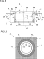
- FIG. 3 a wall of a building (not shown in detail) designed as an outer wall 1 is shown, on which an outer coating compound 2 is provided.
- a pipe 3 leads through this outer wall 1 for draining a flat roof 4, which has thermal insulation 4a.
- the pipe 3 protrudes from the outer wall 1 on the outside of the building (not shown in detail).
- the pipe duct 5 is provided, with its front side 5a facing the outside of the outer wall 1.
- the pipe duct 5 seals the outer wall 1 against the ingress of moisture and/or water.
- the pipe duct 5 shown in more detail has a plastic body 6 made of PVC and a sleeve 7.
- the plastic body 6 has a pipe socket 8 and a flange 9 surrounding the pipe socket 8.
- the pipe 3 leads through the pipe socket 8, as in Fig. 1 can be seen.
- the cuff 7 is firmly connected to the plastic body 6 and protrudes laterally from this plastic body 6.
- the sleeve 7 is flexible. This is achieved in that, according to the invention, the sleeve 7 is formed from a reinforcing fabric 17 in grid form, namely glass fiber grid fabric, as is shown in the Fig. 2 can be recognized in detail. This allows the pipe duct 5 to be firmly embedded in the coating compound 2, namely a plaster compound 2a, of the outer wall 1. Weather-related adversities therefore do not endanger the moisture- and liquid-tight seal between the pipe duct 5 and the outer wall 1.
- An inner seal 10 ensures a stable and tight seal between pipe 3 and plastic body 6.
- This inner seal 10 is designed as a lip seal 10a, which is inserted in a form-fitting manner in an inner recess 11 of the pipe socket 8 and is preferably located in the area of the second pipe end 8b.
- the second pipe end 8b protrudes from the flange back 9b by several times the projection 12 of the pipe end 8a.
- the pipe 3 which runs through the outer wall 1 at an incline of 3 degrees according to the standard, is accommodated coaxially by the pipe duct 5 without jamming.
- the longitudinal axis L of the pipe socket 8 is inclined to the transverse axis Q through the flange 9 at an angle ⁇ ⁇ 90 degrees, namely by exactly 87 degrees.
- the angle ⁇ is therefore in the range from 75 to less than 90 degrees.
- the reinforcing fabric 17 is attached in the connection area 5b of the pipe end 8a of the pipe socket 8 with the flange 9 embedded in the plastic body 6.
- one end 17a of the reinforcing fabric 17 is provided inside the plastic body 6.
- the reinforcing mesh 17 is welded to the flange 9, as shown in Fig. 2 hatched over the reinforcing fabric 17.
- the welding can be carried out, for example, by melting the flange 9 with the possible addition of an additional material, for example polymer, preferably from which the plastic body is made.
- thermal welding can be suitable for this.
- the reinforcing fabric 17 is coated with a plastic finish.
- this plastic finish and the plastic body 6 are made of the same polymer, which facilitates welding.
- the flange 9 has a connection area 18 with the welded reinforcement fabric 17 on the front side 5a of the pipe duct 5 or thus on its flange front 5a.
- This connection area 18 extends over the entire flange front 9a, but a partial area of it is also conceivable.
- the surface Ov of the flange 9 in this connection area 18 is roughened, which ensures a stable, material-locking connection with the reinforcement fabric 17.
- This roughening which can be carried out for example by sand/shot blasting, perforating etc., can be seen in that the surface Ov in this connection area 18 is rougher and thus has an increased average roughness Ra in comparison with an adjoining surface O of the flange 9.
- the Fig. 1 It can be seen that the pipe socket 8 protrudes from the flange 9 on the front side 5a of the pipe duct 5 - namely with one pipe end 8a of two pipe ends 8a, 8b.
- This pipe end 8a forms a plastering edge 13 through this projection 12, as shown in the Fig. 3 to recognize - the plaster compound 2a is flush with the pipe end 8a.
- the pipe end 8a is therefore located on the front side 5a of the pipe duct 5.
- the pipe end 8a is visible on the wall.
- the flange front 9a and the plastering edge 13 are in normal alignment with each other, which ensures easy processing of the pipe duct 5 on the outer wall 1.
- the projection 12 of the plastering edge 13 is preferably 9 mm or 6 mm less than the flange thickness d in millimeters.
- the reinforcing fabric 17 runs over the flange 9 on the front side 5a of the pipe duct 5, which also ensures the adhesion of a coating compound 2 in the area of the flange 9.
- the flange 9 has a flange thickness of 2 to 10 mm and a flange width b of 30 mm.
- the pipe socket 8 has a length l of 37 mm, with the pipe end 8a of the pipe socket 8 projecting seven millimeters beyond the flange 9. With a flange thickness of 2 mm, the second pipe end 8b of the pipe socket 8 therefore projects 28 mm beyond the flange back 9b.
- the pipe socket 8 with its inner diameter di is designed for a pipe 3 with a nominal diameter of DN 100.
Landscapes
- Engineering & Computer Science (AREA)
- General Engineering & Computer Science (AREA)
- Mechanical Engineering (AREA)
- Rigid Pipes And Flexible Pipes (AREA)
- Building Environments (AREA)
Description
Die Erfindung betrifft eine Wand und eine Rohrdurchführung für ein Rohr an einer Wand, insbesondere Außenwand, mit einem Kunststoffkörper, welcher Kunststoffkörper einen Rohrstutzen zur Durchführung des Rohrs sowie einen umlaufenden Flansch am Rohrstutzen aufweist, und mit einer flexiblen Manschette, die mit dem Kunststoffkörper fest verbundenen ist und von diesem seitlich weg steht.The invention relates to a wall and a pipe duct for a pipe on a wall, in particular an external wall, with a plastic body, which plastic body has a pipe socket for the passage of the pipe and a circumferential flange on the pipe socket, and with a flexible sleeve which is firmly connected to the plastic body and projects laterally away from it.
Um den Rohrübergang in eine Wand oder in den Boden gegenüber Flüssigkeiten und Feuchtigkeit abzudichten, ist eine Rohrdurchführung bekannt (
Aus der
Die
Die Erfindung hat sich daher die Aufgabe gestellt, eine Rohrdurchführung zu schaffen, die an einer Außenwand standfest eingesetzt werden kann.The invention therefore has the task of creating a pipe duct that can be used stably on an external wall.
Die Erfindung löst die gestellte Aufgabe durch die Merkmale des Anspruchs 1.The invention solves the problem by the features of
Wird die Manschette von einem Armierungsgewebe in Gitterform ausgebildet, kann die Rohrdurchführung auch standfest an einer Außenwand vorgesehen werden, da durch die Flexibilität und der gleichzeitig hohen Zugfestigkeit des Armierungsgewebes eine besonders standfeste Verbindung mit der Außenwand erreichbar ist. Insbesondere kann damit im Vergleich mit einer Folien-Manschette auch die Dehnung der Manschette erfindungsgemäß gering bleiben, was Risse in der Außenwand vermeidet - und damit die Gefahr eines Eintretens von Feuchtigkeit und Flüssigkeiten in die Wand reduziert. Eine standfeste Rohrdurchführung ist damit geschaffen, welche insbesondere auch widrigen Umwelteinflüssen trotzen kann, wie diese an einer Außenwand herrschen.If the sleeve is made of a reinforcing mesh in the form of a grid, the pipe duct can also be installed securely on an external wall, as the flexibility and high tensile strength of the reinforcing mesh allow a particularly stable connection to the external wall. In particular, compared to a foil sleeve, the expansion of the sleeve can remain low according to the invention, which prevents cracks in the external wall - and thus reduces the risk of moisture and liquids entering the wall. This creates a stable pipe duct that can withstand adverse environmental influences, such as those found on an external wall.
Als Armierungsgewebe in Gitterform ist ein Glasfasergittergewebe, Polyestergittergewebe etc. denkbar. Das Armierungsgewebe kann mit einer Kunststoffappretur beschichtet sein. Der Kunststoffkörper ist vorzugsweise aus einem PVC Material, wobei auch ein PP Material denkbar ist.A glass fiber mesh, polyester mesh, etc. can be used as a reinforcing mesh in grid form. The reinforcing mesh can be coated with a plastic finish. The plastic body is preferably made of a PVC material, although a PP material is also possible.
Vorzugsweise kann der Rohrstutzen eine Innendichtung, insbesondere eine Lippendichtung, aufweisen, um zusätzlich einen standfesten, flüssigkeitsdichten Abschluss mit dem durchzuführenden Rohr zu ermöglichen.Preferably, the pipe socket can have an internal seal, in particular a lip seal, in order to additionally enable a stable, liquid-tight seal with the pipe to be passed through.
Indem die Längsachse des Rohrstutzens zur Querachse durch den Flansch in einem Winkel α < 90 Grad geneigt ist, kann die Montage des Rohrstutzens erleichtert werden - dies insbesondere, weil Rohre für einen Wasserablauf in der Regel die Außenwand geneigt verlaufend durchstoßen. Es bedarf daher keines Verkippens des Rohrstutzens gegenüber der meist senkrecht verlaufenden Außenwand, um das Rohr geneigt durchzuführen bzw. in der Montagelage aufnehmen zu können.By having the longitudinal axis of the pipe socket inclined to the transverse axis through the flange at an angle of α < 90 degrees, the installation of the pipe socket can be made easier - this is particularly true because pipes for water drainage usually penetrate the outer wall at an angle. It is therefore not necessary to tilt the pipe socket relative to the usually vertical outer wall in order to be able to pass the pipe through at an angle or to accommodate it in the installation position.
Insbesondere, wenn dieser Winkel α im Bereich von 75 bis kleiner 90 Grad liegt, kann im Wesentlich jede genormte Neigung der verlegten Rohre vom Rohrstutzen aufgenommen werden. Als besonders geeignet können sich diesbezüglich 87 Grad erweisen.In particular, if this angle α is in the range of 75 to less than 90 degrees, essentially any standardized inclination of the installed pipes can be accommodated by the pipe socket. 87 degrees can prove to be particularly suitable in this regard.
Die Konstruktion der Rohrdurchführung kann sich weiter vereinfachen, wenn das Armierungsgewebe mit dem Flansch verschweißt ist. Vorzugsweise ist das Armierungsgewebe mit dem Flansch an dessen Flanschfront verschweißt.The design of the pipe penetration can be further simplified if the reinforcing mesh is welded to the flange. Preferably, the reinforcing mesh is welded to the flange at its flange front.
Die Schweißverbindung kann in der Festigkeit weiter verbessert werden, der Flansch einen Verbindungsbereich mit dem verschweißten Armierungsgewebe aufweist, wobei in diesem Verbindungsbereich die Oberfläche eine im Vergleich mit einer daran anschließenden Oberfläche der Rohrdurchführung, insbesondere des Flansches, erhöhte mittlere Rauigkeit aufweist. Solche eine Oberfläche im Verbindungsbereich kann durch Aufrauen beispielsweise mit Quarzsand etc. geschaffen werden.The strength of the welded connection can be further improved if the flange has a connection area with the welded reinforcing fabric, wherein in this connection area the surface has an increased average roughness compared to an adjoining surface of the pipe duct, in particular the flange. Such a surface in the connection area can be created by roughening, for example with quartz sand, etc.
Weiter ist vorstellbar, dass das Armierungsgewebe in den Kunststoffkörper eingebettet befestigt ist. Dies kann zudem den Verbund zwischen Armierungsgewebe und Kunststoffkörper besonders stärken, um dadurch eine erhöhte Standfestigkeit selbst äußersten witterungsbedingten Widrigkeiten sicherstellen zu können.It is also conceivable that the reinforcing mesh is embedded in the plastic body. This can also strengthen the bond between the reinforcing mesh and the plastic body, thereby ensuring increased stability even in the most extreme weather conditions.
Die Montage und insbesondere das Einbetten der Rohrdurchführung in eine Beschichtung der Wand kann weiter erleichtert werden, wenn auf der Frontseite der Rohrdurchführung ein Rohrende des Rohrstutzens dem Flansch überstehen und damit eine Anputzkante ausbildet. Zudem ist durch die Anputzkante die Lage der Rohrdurchführung an der Wand auf einfache Weise zu überprüfen - was in folglich auch die Handhabung der Rohrdurchführung erleichtern kann.The installation and especially the embedding of the pipe penetration into a coating of the wall can be further facilitated if on the front side of the Pipe feedthrough, one pipe end of the pipe socket protrudes from the flange and thus forms a plastering edge. In addition, the plastering edge makes it easy to check the position of the pipe feedthrough on the wall - which can also make handling the pipe feedthrough easier.
Indem das Armierungsgewebe im Anschlussbereich des Rohrendes mit dem Flansch in den Kunststoffkörper eingebettet befestigt ist, kann die Rohrdurchführung bis zur Anputzkante hin standfest in einer Wandbeschichtung eingebettet werden.By attaching the reinforcing mesh in the connection area of the pipe end with the flange embedded in the plastic body, the pipe duct can be firmly embedded in a wall coating up to the plaster edge.
Vorzugsweise verläuft das Armierungsgewebe über den Flansch auf der Frontseite der Rohrdurchführung, um ein Einbetten der Rohrdurchführung in einer Beschichtung der Wand erleichtern kann.Preferably, the reinforcing mesh runs over the flange on the front side of the pipe penetration to facilitate embedding the pipe penetration in a coating of the wall.
Die Handhabbarkeit der Rohrdurchführung ist weiter zu erleichtern, wenn der Flansch eine Flanschdicke von 2 bis 10 mm (Millimeter) aufweist. Dies umso mehr, wenn der Flansch eine Flanschbreite von 25 bis 35 mm aufweist. Vorzugsweise beträgt die Flanschbreite 30 mm, was beispielsweise für eine ausreichende Anbindungsfläche für das Armierungsgewebe sorgen kann.The handling of the pipe penetration is made even easier if the flange has a flange thickness of 2 to 10 mm (millimeters). This is even more so if the flange has a flange width of 25 to 35 mm. The flange width is preferably 30 mm, which can provide a sufficient connection surface for the reinforcing mesh, for example.
Vorteilhaft hinsichtlich der Handhabung beispielsweise bei der Montage kann weiter sein, wenn der Rohrstutzen eine Länge bis zu 50 mm aufweist. Als ausreichend für eine vielseitige Anwendbarkeit der Rohrdurchführung kann sich bereits herausstellen, wenn der Rohrstutzen einen Innendurchmesser aufweist, der zur Durchführung eines Rohrs mit einer Nennweite von zumindest DN 50, insbesondere zumindest DN 100, ausgebildeten ist.It can also be advantageous in terms of handling, for example during assembly, if the pipe socket has a length of up to 50 mm. It can already prove sufficient for versatile use of the pipe feedthrough if the pipe socket has an inner diameter that is designed to pass through a pipe with a nominal width of at least DN 50, in particular at least DN 100.
Die Rohrdurchführung lässt sich beispielsweise handhabungsfreundlicher an einer Außenwand platzieren, wenn Flanschfront und Anputzkante normal aufeinander stehen.For example, the pipe duct can be placed on an external wall for easier handling if the flange front and plaster edge are in normal alignment with each other.
Als ausreichend zum Anputzen der Rohrdurchführung kann sich herausstellen, wenn das Rohrende dem Flansch im Bereich von 4 bis 9 mm (Millimeter). Beispielsweise 7 mm können zu einem Optimum in der Handhabung führen.It may be sufficient to clean the pipe duct if the pipe end is within 4 to 9 mm (millimeters) of the flange. For example, 7 mm can lead to optimum handling.
Vorzugsweise ist der Überstand des Rohrendes in Millimeter zusammen mit der Flanschdicke in Millimeter im Bereich von 5 bis 11 mm, insbesondere entweder 6 mm oder 9 mm, was eine einfache Handhabung der Rohrdurchführung beim Verputzen verschiedenster Beschichtungsmassen sicherstellen kann.Preferably, the projection of the pipe end in millimeters together with the flange thickness in millimeters is in the range of 5 to 11 mm, in particular either 6 mm or 9 mm, which can ensure easy handling of the pipe duct when plastering a wide variety of coating compounds.
Die Rohrdurchführung findet bevorzugt an einer Wand, insbesondere Außenwand, mit einer äußeren Beschichtungsmasse Verwendung. Insbesondere ist dabei das Armierungsgewebe der Rohrdurchführung in der Beschichtungsmasse, welche insbesondere eine Putzmasse und/oder Spachtelmasse ist, eingebettet.The pipe duct is preferably used on a wall, in particular an external wall, with an external coating compound. In particular, the reinforcing fabric of the pipe duct is embedded in the coating compound, which is in particular a plaster compound and/or filler compound.
Zudem kann die Wand ein Rohr zur Entwässerung eines Dachs, insbesondere Flachdachs, aufweisen. Erfindungsgemäß wird bei dem die Rohrdurchführung durchdringenden Rohr ein besonders feuchtigkeits- und flüssigkeitsdichter Abschluss der Außenwand im Bereich der Rohröffnung sichergestellt.In addition, the wall can have a pipe for draining a roof, in particular a flat roof. According to the invention, the pipe penetrating the pipe duct ensures a particularly moisture- and liquid-tight seal of the outer wall in the area of the pipe opening.
In den Figuren ist der Erfindungsgegenstand anhand eines Ausführungsbeispiels näher dargestellt. Es zeigen
-
Fig. 1 eine Schnittansicht auf eine Rohrdurchführung, -
Fig. 2 eine Draufsicht auf die Rohrdurchführung nachFig. 1 und -
Fig. 3 eine aufgerissene Seitenansicht auf eine Wand mit der Rohrdurchführung nach denFiguren 1 und 2
-
Fig. 1 a sectional view of a pipe penetration, -
Fig. 2 a top view of the pipe penetration according toFig. 1 and -
Fig. 3 a side view of a wall with the pipe penetration according to theFigures 1 and 2 .
Nach
Das Rohr 3 steht der Außenwand 1 auf der Außenseite des nicht näher dargestellten Gebäudes vor. Um einen Spalt zwischen Außenwand 1 und Rohr 3 zu vermeiden, ist die Rohrdurchführung 5 vorgesehen, und zwar mit seiner Frontseite 5a der Außenseite der Außenwand 1 zugewandt. Die Rohrdurchführung 5 dichtet die Außenwand 1 gegenüber einem Eindringen von Feuchtigkeit und/oder Wasser ab.The
Diese in den
Die Manschette 7 ist flexibel. Dies in dem erfindungsgemäß die Manschette 7 von einem Armierungsgewebe 17 in Gitterform, nämlich Glasfasergittergewebe, ausgebildet wird, wie dies in der
Für einen standfesten und dichten Abschluss zwischen Rohr 3 und Kunststoffkörper 6 sorgt eine Innendichtung 10. Diese Innendichtung 10 ist als Lippendichtung 10a ausgeführt, die formschlüssig in einer innenseitigen Ausnehmung 11 des Rohrstutzens 8 eingesetzt und befindet sich bevorzugt im Bereich des zweiten Rohrendes 8b.An
Das zweite Rohrende 8b steht dem Flanschrücken 9b vor, und zwar um das mehrfache des Überstands 12 des Rohrendes 8a.The
Das nach Norm um 3 Grad geneigt durch die Außenwand 1 verlaufende Rohr 3 wird von der Rohrdurchführung 5 koaxial verkanntungsfrei aufgenommen. Hierzu ist die Längsachse L des Rohrstutzens 8 zur Querachse Q durch den Flansch 9 in einem Winkel α < 90 Grad geneigt, und zwar um exakt 87 Grad. Der Winkel α liegt daher im Bereich von 75 bis kleiner 90 Grad.The
Wie in der
Zusätzlich oder auch alternativ dazu ist das Armierungsgewebe 17 mit dem Flansch 9 verschweißt, wie das in
Beim Verschweißen kann auch dienlich sein, wenn das Armierungsgewebe 17 mit einer Kunststoffappretur beschichtet ist. Vorzugsweise sind diese Kunststoffappretur und der Kunststoffkörper 6 aus dem gleichen Polymer, was das Verschweißen erleichtert.When welding, it can also be helpful if the reinforcing
Der Flansch 9 weist hierzu an der Frontseite 5a der Rohrdurchführung 5 bzw. damit an dessen Flanschfront 5a einen Verbindungsbereich 18 mit dem verschweißten Armierungsgewebe 17 auf. Dieser Verbindungsbereich 18 erstreckt sich über die gesamte Flanschfront 9a, wobei aber auch ein Teilebereich davon vorstellbar ist. Die Oberfläche Ov des Flansches 9 in diesem Verbindungsbereich 18 ist aufgeraut, was eine standfeste stoffschlüssige Verbindung mit dem Armierungsgewebe 17 sicherstellt. Erkennbar ist diese Aufrauung, was beispielsweise durch Sand/Kugelstrahlen, Perforieren etc. durchgeführt werden kann, dass in diesem Verbindungsbereich 18 die Oberfläche Ov rauer ist und damit im Vergleich mit einer daran anschließenden Oberfläche O des Flansches 9 erhöhte mittlere Rauigkeit Ra aufweist.For this purpose, the
Zudem ist in der
Die Flanschfront 9a und die Anputzkante 13 stehen normal aufeinander, was für eine einfache Verarbeitung der Rohrdurchführung 5 an der Außenwand 1 sorgt.The
Der Überstand 12 der Anputzkante 13 ist vorzugsweise 9 mm oder 6 mm weniger der Flanschdicke d in Millimeter.The
Zudem läuft das Armierungsgewebe 17 über den Flansch 9 an der Frontseite 5a der Rohrdurchführung 5, womit auch im Bereich des Flansches 9 das Anhaften einer Beschichtungsmasse 2 sichergestellt ist.In addition, the reinforcing
Vorzugsweise weist der Flansch 9 eine Flanschdicke von 2 bis 10 mm und eine Flanschbreite b von 30 mm auf. Der Rohrstutzen 8 weist eine Länge l von 37 mm auf, wobei das Rohrende 8a des Rohrstutzens 8 dem Flansch 9 sieben Millimeter übersteht. Mit einer Flanschdicke von 2 mm steht daher das zweite Rohrende 8b des Rohrstutzens 8 28 mm dem Flanschrücken 9b vor.Preferably, the
Der Rohrstutzen 8 ist mit dessen Innendurchmesser di für ein Rohr 3 mit einer Nennweite von DN 100 ausgelegt.The
Claims (17)
- Pipe feedthrough for insertion in a wall, for a pipe (3) on this wall, more particularly an outer wall (1), having a plastic body (6), which plastic body (6) has a pipe socket (8) for the pipe (3) to pass through and also a peripheral flange (9) on the pipe socket (8), and having a flexible sleeve (7) which is firmly connected to the plastic body (6) and projects laterally away therefrom, characterized in that the sleeve (7) is formed in the shape of a grid by a reinforcing fabric (17).
- Pipe feedthrough according to claim 1, characterized in that the pipe socket (8) has an internal seal (10), more particularly a lip seal (10a).
- Pipe feedthrough according to claim 1 or 2, characterized in that the longitudinal axis (L) of the pipe socket (8) is inclined at an angle (α) <90 degrees to the transverse axis (Q) through the flange (9).
- Pipe feedthrough according to claim 3, characterized in that the angle (α) is in the range from 75 to less than 90 degrees, more particularly 87 degrees.
- Pipe feedthrough according to one of claims 1 to 4, characterized in that the reinforcing fabric (17) is welded to the flange (9), more particularly on the flange front (9a) thereof.
- Pipe feedthrough according to claim 5, characterized in that the flange (9) has a connecting region (18) with the welded reinforcing fabric (17), wherein the surface (Ov) in this connecting region (18) has a higher mean roughness (Ra) in comparison with an adjoining surface (O) of the pipe feedthrough (5), more particularly of the flange (9).
- Pipe feedthrough according to one of claims 1 to 6, characterized in that the reinforcing fabric (17) is embedded in the plastic body (6).
- Pipe feedthrough according to one of claims 1 to 7, characterized in that, on the front side (5a) of the pipe feedthrough (5), one pipe end (8a) of the pipe socket (8) projects beyond the flange (9) and thus forms a plastering edge (13).
- Pipe feedthrough according to claim 8, characterized in that the reinforcing fabric (17) is attached in the connecting region (5b) of the pipe end (8a) with the flange (9) embedded in the plastic body (6).
- Pipe feedthrough according to claim 8 or 9, characterized in that the flange front (5a) and plastering edge (13) are disposed normally to one another.
- Pipe feedthrough according to claim 8, 9 or 10, characterized in that the pipe end (8a) projects beyond the flange (9) in the range from 4 to 9 mm, more particularly 7 mm.
- Pipe feedthrough according to claim 8, 9, 10 or 11, characterized in that the projection (12) of the pipe end (8a) in millimeters together with the flange thickness (d) in millimeters is in the range from 5 to 11 mm, more particularly either 6 mm or 9 mm.
- Pipe feedthrough according to one of claims 1 to 12, characterized in that the reinforcing fabric (17) extends over the flange (9) on the front side (5a) of the pipe feedthrough (5).
- Pipe feedthrough according to one of claims 1 to 13, characterized in that the flange (9) has a flange thickness (d) of 2 to 10 mm, more particularly 2 mm, and/or a flange width (b) of 25 to 35 mm, more particularly 30 mm.
- Pipe feedthrough according to one of claims 1 to 14, characterized in that the pipe socket (8) has a length (l) of up to 50 mm, more particularly 37 mm, and/or an internal diameter (di) which is designed for the passage of a pipe having a nominal width of at least DN 50, more particularly DN 100.
- Wall, more particularly an external wall (1), having an external coating composition (2), more particularly a plaster composition (2a) and/or filler composition, and having a pipe feedthrough (5) according to one of claims 1 to 15, wherein the reinforcing fabric (17) of the pipe feedthrough (5) is embedded in the coating composition (2).
- Wall according to claim 16, characterized in that the wall has a pipe (3) for draining a roof, more particularly a flat roof (4), and in that the pipe (3) passes through the pipe feedthrough (5).
Applications Claiming Priority (2)
| Application Number | Priority Date | Filing Date | Title |
|---|---|---|---|
| AT603812020 | 2020-12-30 | ||
| PCT/AT2021/060497 WO2022140815A1 (en) | 2020-12-30 | 2021-12-30 | Wall and pipe feedthrough for a pipe on said wall |
Publications (3)
| Publication Number | Publication Date |
|---|---|
| EP4271925A1 EP4271925A1 (en) | 2023-11-08 |
| EP4271925C0 EP4271925C0 (en) | 2025-02-19 |
| EP4271925B1 true EP4271925B1 (en) | 2025-02-19 |
Family
ID=80222280
Family Applications (1)
| Application Number | Title | Priority Date | Filing Date |
|---|---|---|---|
| EP21854803.0A Active EP4271925B1 (en) | 2020-12-30 | 2021-12-30 | Wall and pipe feedthrough for a pipe on said wall |
Country Status (3)
| Country | Link |
|---|---|
| EP (1) | EP4271925B1 (en) |
| PL (1) | PL4271925T3 (en) |
| WO (1) | WO2022140815A1 (en) |
Family Cites Families (4)
| Publication number | Priority date | Publication date | Assignee | Title |
|---|---|---|---|---|
| CH673866A5 (en) | 1987-07-24 | 1990-04-12 | Geberit Ag | |
| DE19544957A1 (en) * | 1995-12-02 | 1997-06-05 | Gefinex Jackon Gmbh | Sealing sleeve for pipes for building industry |
| DE202018001460U1 (en) * | 2018-03-19 | 2018-04-12 | Claus Cichos | Insulated facade composite with openings |
| WO2019211467A1 (en) * | 2018-05-04 | 2019-11-07 | Sopro Bauchemie Gmbh | Sealing collar for composite seals |
-
2021
- 2021-12-30 PL PL21854803.0T patent/PL4271925T3/en unknown
- 2021-12-30 EP EP21854803.0A patent/EP4271925B1/en active Active
- 2021-12-30 WO PCT/AT2021/060497 patent/WO2022140815A1/en not_active Ceased
Also Published As
| Publication number | Publication date |
|---|---|
| EP4271925C0 (en) | 2025-02-19 |
| WO2022140815A1 (en) | 2022-07-07 |
| PL4271925T3 (en) | 2025-06-23 |
| EP4271925A1 (en) | 2023-11-08 |
Similar Documents
| Publication | Publication Date | Title |
|---|---|---|
| DE3644834C1 (en) | Pipe connector made of socket and insert | |
| DE2629214A1 (en) | METHOD AND MEANS OF LINING PIPELINE | |
| EP0532459B1 (en) | Junction sleeve for two plastic pipes. | |
| EP1479838B1 (en) | Plastic drainage channel | |
| CH492839A (en) | Set of parts to form a soil and surface drainage system | |
| DE2615428A1 (en) | Tube joint for masonry or concrete wall - has sockets for seals and plain tube ends for flexible connection | |
| EP4271925B1 (en) | Wall and pipe feedthrough for a pipe on said wall | |
| AT524281B1 (en) | Channel body, connecting device, end wall, drainage channel, arrangement and method | |
| EP2295655A2 (en) | Shaft, in particular control and rinsing shaft for waste water with a flow channel and board for same | |
| DE1759682A1 (en) | Inlet shaft and shaft bottom made of plastic | |
| DE9416411U1 (en) | Pipe, especially plastic pipe, and pipe connection from such pipes | |
| DE202011050243U1 (en) | Implementation for a building envelope | |
| DE202005007835U1 (en) | Ventilation pipe for building has accordion pleated outer wall and connected inner wall of rectangular or oval section | |
| EP3848512B1 (en) | Method for creating a foundation element in the ground and foundation element | |
| DE19745599C2 (en) | Composite pipe and process for its manufacture | |
| DE2553388A1 (en) | Prefabricated inspection shaft with pipe connections - has spherical concave seats for convex pipe ends for angular positioning | |
| AT520104B1 (en) | Light shaft extension element and method for the installation of a light shaft extension element in a watertight manner | |
| DE202009016484U1 (en) | Sleeve anchor for placement in a concrete part | |
| DE202007005696U1 (en) | Tubular component for the production of lines, shafts, fittings and the like. | |
| DE4443983C2 (en) | Shaft arrangement | |
| EP1591712A2 (en) | Pipe-connecting arrangement and its application | |
| DD296133A5 (en) | PROCESS FOR THE PRODUCTION OF VIRGIN | |
| DE102016103275A1 (en) | Seal of a drainage channel | |
| DE202023100529U1 (en) | Connection system | |
| DE202025102041U1 (en) | Sealing element for cable penetrations |
Legal Events
| Date | Code | Title | Description |
|---|---|---|---|
| STAA | Information on the status of an ep patent application or granted ep patent |
Free format text: STATUS: UNKNOWN |
|
| STAA | Information on the status of an ep patent application or granted ep patent |
Free format text: STATUS: THE INTERNATIONAL PUBLICATION HAS BEEN MADE |
|
| PUAI | Public reference made under article 153(3) epc to a published international application that has entered the european phase |
Free format text: ORIGINAL CODE: 0009012 |
|
| STAA | Information on the status of an ep patent application or granted ep patent |
Free format text: STATUS: REQUEST FOR EXAMINATION WAS MADE |
|
| 17P | Request for examination filed |
Effective date: 20230725 |
|
| AK | Designated contracting states |
Kind code of ref document: A1 Designated state(s): AL AT BE BG CH CY CZ DE DK EE ES FI FR GB GR HR HU IE IS IT LI LT LU LV MC MK MT NL NO PL PT RO RS SE SI SK SM TR |
|
| RAP1 | Party data changed (applicant data changed or rights of an application transferred) |
Owner name: KIRCHHOFER, THOMAS Owner name: SCHOERFLINGER, ALEXANDER |
|
| RIN1 | Information on inventor provided before grant (corrected) |
Inventor name: SCHOERFLINGER, ALEXANDER |
|
| RIN1 | Information on inventor provided before grant (corrected) |
Inventor name: KIRCHHOFER, THOMAS Inventor name: SCHOERFLINGER, ALEXANDER |
|
| DAV | Request for validation of the european patent (deleted) | ||
| GRAP | Despatch of communication of intention to grant a patent |
Free format text: ORIGINAL CODE: EPIDOSNIGR1 |
|
| STAA | Information on the status of an ep patent application or granted ep patent |
Free format text: STATUS: GRANT OF PATENT IS INTENDED |
|
| INTG | Intention to grant announced |
Effective date: 20240904 |
|
| GRAS | Grant fee paid |
Free format text: ORIGINAL CODE: EPIDOSNIGR3 |
|
| GRAA | (expected) grant |
Free format text: ORIGINAL CODE: 0009210 |
|
| STAA | Information on the status of an ep patent application or granted ep patent |
Free format text: STATUS: THE PATENT HAS BEEN GRANTED |
|
| RAP3 | Party data changed (applicant data changed or rights of an application transferred) |
Owner name: KIRCHHOFER, THOMAS Owner name: SCHOERFLINGER, ALEXANDER |
|
| RIN1 | Information on inventor provided before grant (corrected) |
Inventor name: KIRCHHOFER, THOMAS Inventor name: SCHOERFLINGER, ALEXANDER |
|
| AK | Designated contracting states |
Kind code of ref document: B1 Designated state(s): AL AT BE BG CH CY CZ DE DK EE ES FI FR GB GR HR HU IE IS IT LI LT LU LV MC MK MT NL NO PL PT RO RS SE SI SK SM TR |
|
| REG | Reference to a national code |
Ref country code: GB Ref legal event code: FG4D Free format text: NOT ENGLISH |
|
| REG | Reference to a national code |
Ref country code: CH Ref legal event code: EP |
|
| REG | Reference to a national code |
Ref country code: IE Ref legal event code: FG4D Free format text: LANGUAGE OF EP DOCUMENT: GERMAN |
|
| REG | Reference to a national code |
Ref country code: DE Ref legal event code: R096 Ref document number: 502021006732 Country of ref document: DE |
|
| U01 | Request for unitary effect filed |
Effective date: 20250319 |
|
| U07 | Unitary effect registered |
Designated state(s): AT BE BG DE DK EE FI FR IT LT LU LV MT NL PT RO SE SI Effective date: 20250324 |
|
| PG25 | Lapsed in a contracting state [announced via postgrant information from national office to epo] |
Ref country code: RS Free format text: LAPSE BECAUSE OF FAILURE TO SUBMIT A TRANSLATION OF THE DESCRIPTION OR TO PAY THE FEE WITHIN THE PRESCRIBED TIME-LIMIT Effective date: 20250519 |
|
| PG25 | Lapsed in a contracting state [announced via postgrant information from national office to epo] |
Ref country code: ES Free format text: LAPSE BECAUSE OF FAILURE TO SUBMIT A TRANSLATION OF THE DESCRIPTION OR TO PAY THE FEE WITHIN THE PRESCRIBED TIME-LIMIT Effective date: 20250219 |
|
| PG25 | Lapsed in a contracting state [announced via postgrant information from national office to epo] |
Ref country code: IS Free format text: LAPSE BECAUSE OF FAILURE TO SUBMIT A TRANSLATION OF THE DESCRIPTION OR TO PAY THE FEE WITHIN THE PRESCRIBED TIME-LIMIT Effective date: 20250619 Ref country code: NO Free format text: LAPSE BECAUSE OF FAILURE TO SUBMIT A TRANSLATION OF THE DESCRIPTION OR TO PAY THE FEE WITHIN THE PRESCRIBED TIME-LIMIT Effective date: 20250519 |
|
| PG25 | Lapsed in a contracting state [announced via postgrant information from national office to epo] |
Ref country code: HR Free format text: LAPSE BECAUSE OF FAILURE TO SUBMIT A TRANSLATION OF THE DESCRIPTION OR TO PAY THE FEE WITHIN THE PRESCRIBED TIME-LIMIT Effective date: 20250219 |
|
| REG | Reference to a national code |
Ref country code: SK Ref legal event code: T3 Ref document number: E 46385 Country of ref document: SK |
|
| PG25 | Lapsed in a contracting state [announced via postgrant information from national office to epo] |
Ref country code: GR Free format text: LAPSE BECAUSE OF FAILURE TO SUBMIT A TRANSLATION OF THE DESCRIPTION OR TO PAY THE FEE WITHIN THE PRESCRIBED TIME-LIMIT Effective date: 20250520 |
|
| PG25 | Lapsed in a contracting state [announced via postgrant information from national office to epo] |
Ref country code: SM Free format text: LAPSE BECAUSE OF FAILURE TO SUBMIT A TRANSLATION OF THE DESCRIPTION OR TO PAY THE FEE WITHIN THE PRESCRIBED TIME-LIMIT Effective date: 20250219 |