EP4269863A1 - Paroi de cuve comportant une conduite traversante - Google Patents
Paroi de cuve comportant une conduite traversante Download PDFInfo
- Publication number
- EP4269863A1 EP4269863A1 EP23169330.0A EP23169330A EP4269863A1 EP 4269863 A1 EP4269863 A1 EP 4269863A1 EP 23169330 A EP23169330 A EP 23169330A EP 4269863 A1 EP4269863 A1 EP 4269863A1
- Authority
- EP
- European Patent Office
- Prior art keywords
- thermally insulating
- waterproof
- primary
- tank
- pipe
- Prior art date
- Legal status (The legal status is an assumption and is not a legal conclusion. Google has not performed a legal analysis and makes no representation as to the accuracy of the status listed.)
- Pending
Links
Images


Classifications
-
- F—MECHANICAL ENGINEERING; LIGHTING; HEATING; WEAPONS; BLASTING
- F17—STORING OR DISTRIBUTING GASES OR LIQUIDS
- F17C—VESSELS FOR CONTAINING OR STORING COMPRESSED, LIQUEFIED OR SOLIDIFIED GASES; FIXED-CAPACITY GAS-HOLDERS; FILLING VESSELS WITH, OR DISCHARGING FROM VESSELS, COMPRESSED, LIQUEFIED, OR SOLIDIFIED GASES
- F17C13/00—Details of vessels or of the filling or discharging of vessels
- F17C13/004—Details of vessels or of the filling or discharging of vessels for large storage vessels not under pressure
-
- F—MECHANICAL ENGINEERING; LIGHTING; HEATING; WEAPONS; BLASTING
- F17—STORING OR DISTRIBUTING GASES OR LIQUIDS
- F17C—VESSELS FOR CONTAINING OR STORING COMPRESSED, LIQUEFIED OR SOLIDIFIED GASES; FIXED-CAPACITY GAS-HOLDERS; FILLING VESSELS WITH, OR DISCHARGING FROM VESSELS, COMPRESSED, LIQUEFIED, OR SOLIDIFIED GASES
- F17C3/00—Vessels not under pressure
- F17C3/02—Vessels not under pressure with provision for thermal insulation
- F17C3/025—Bulk storage in barges or on ships
-
- B—PERFORMING OPERATIONS; TRANSPORTING
- B63—SHIPS OR OTHER WATERBORNE VESSELS; RELATED EQUIPMENT
- B63B—SHIPS OR OTHER WATERBORNE VESSELS; EQUIPMENT FOR SHIPPING
- B63B25/00—Load-accommodating arrangements, e.g. stowing, trimming; Vessels characterised thereby
- B63B25/02—Load-accommodating arrangements, e.g. stowing, trimming; Vessels characterised thereby for bulk goods
- B63B25/08—Load-accommodating arrangements, e.g. stowing, trimming; Vessels characterised thereby for bulk goods fluid
- B63B25/12—Load-accommodating arrangements, e.g. stowing, trimming; Vessels characterised thereby for bulk goods fluid closed
- B63B25/16—Load-accommodating arrangements, e.g. stowing, trimming; Vessels characterised thereby for bulk goods fluid closed heat-insulated
-
- B—PERFORMING OPERATIONS; TRANSPORTING
- B63—SHIPS OR OTHER WATERBORNE VESSELS; RELATED EQUIPMENT
- B63B—SHIPS OR OTHER WATERBORNE VESSELS; EQUIPMENT FOR SHIPPING
- B63B27/00—Arrangement of ship-based loading or unloading equipment for cargo or passengers
- B63B27/24—Arrangement of ship-based loading or unloading equipment for cargo or passengers of pipe-lines
-
- B—PERFORMING OPERATIONS; TRANSPORTING
- B63—SHIPS OR OTHER WATERBORNE VESSELS; RELATED EQUIPMENT
- B63B—SHIPS OR OTHER WATERBORNE VESSELS; EQUIPMENT FOR SHIPPING
- B63B27/00—Arrangement of ship-based loading or unloading equipment for cargo or passengers
- B63B27/30—Arrangement of ship-based loading or unloading equipment for transfer at sea between ships or between ships and off-shore structures
- B63B27/34—Arrangement of ship-based loading or unloading equipment for transfer at sea between ships or between ships and off-shore structures using pipe-lines
-
- F—MECHANICAL ENGINEERING; LIGHTING; HEATING; WEAPONS; BLASTING
- F17—STORING OR DISTRIBUTING GASES OR LIQUIDS
- F17C—VESSELS FOR CONTAINING OR STORING COMPRESSED, LIQUEFIED OR SOLIDIFIED GASES; FIXED-CAPACITY GAS-HOLDERS; FILLING VESSELS WITH, OR DISCHARGING FROM VESSELS, COMPRESSED, LIQUEFIED, OR SOLIDIFIED GASES
- F17C13/00—Details of vessels or of the filling or discharging of vessels
-
- F—MECHANICAL ENGINEERING; LIGHTING; HEATING; WEAPONS; BLASTING
- F17—STORING OR DISTRIBUTING GASES OR LIQUIDS
- F17C—VESSELS FOR CONTAINING OR STORING COMPRESSED, LIQUEFIED OR SOLIDIFIED GASES; FIXED-CAPACITY GAS-HOLDERS; FILLING VESSELS WITH, OR DISCHARGING FROM VESSELS, COMPRESSED, LIQUEFIED, OR SOLIDIFIED GASES
- F17C3/00—Vessels not under pressure
- F17C3/02—Vessels not under pressure with provision for thermal insulation
- F17C3/025—Bulk storage in barges or on ships
- F17C3/027—Wallpanels for so-called membrane tanks
-
- F—MECHANICAL ENGINEERING; LIGHTING; HEATING; WEAPONS; BLASTING
- F17—STORING OR DISTRIBUTING GASES OR LIQUIDS
- F17C—VESSELS FOR CONTAINING OR STORING COMPRESSED, LIQUEFIED OR SOLIDIFIED GASES; FIXED-CAPACITY GAS-HOLDERS; FILLING VESSELS WITH, OR DISCHARGING FROM VESSELS, COMPRESSED, LIQUEFIED, OR SOLIDIFIED GASES
- F17C3/00—Vessels not under pressure
- F17C3/02—Vessels not under pressure with provision for thermal insulation
- F17C3/04—Vessels not under pressure with provision for thermal insulation by insulating layers
-
- F—MECHANICAL ENGINEERING; LIGHTING; HEATING; WEAPONS; BLASTING
- F17—STORING OR DISTRIBUTING GASES OR LIQUIDS
- F17C—VESSELS FOR CONTAINING OR STORING COMPRESSED, LIQUEFIED OR SOLIDIFIED GASES; FIXED-CAPACITY GAS-HOLDERS; FILLING VESSELS WITH, OR DISCHARGING FROM VESSELS, COMPRESSED, LIQUEFIED, OR SOLIDIFIED GASES
- F17C6/00—Methods and apparatus for filling vessels not under pressure with liquefied or solidified gases
-
- F—MECHANICAL ENGINEERING; LIGHTING; HEATING; WEAPONS; BLASTING
- F17—STORING OR DISTRIBUTING GASES OR LIQUIDS
- F17C—VESSELS FOR CONTAINING OR STORING COMPRESSED, LIQUEFIED OR SOLIDIFIED GASES; FIXED-CAPACITY GAS-HOLDERS; FILLING VESSELS WITH, OR DISCHARGING FROM VESSELS, COMPRESSED, LIQUEFIED, OR SOLIDIFIED GASES
- F17C9/00—Methods or apparatus for discharging liquefied or solidified gases from vessels not under pressure
-
- F—MECHANICAL ENGINEERING; LIGHTING; HEATING; WEAPONS; BLASTING
- F17—STORING OR DISTRIBUTING GASES OR LIQUIDS
- F17C—VESSELS FOR CONTAINING OR STORING COMPRESSED, LIQUEFIED OR SOLIDIFIED GASES; FIXED-CAPACITY GAS-HOLDERS; FILLING VESSELS WITH, OR DISCHARGING FROM VESSELS, COMPRESSED, LIQUEFIED, OR SOLIDIFIED GASES
- F17C2201/00—Vessel construction, in particular geometry, arrangement or size
- F17C2201/01—Shape
- F17C2201/0147—Shape complex
- F17C2201/0157—Polygonal
-
- F—MECHANICAL ENGINEERING; LIGHTING; HEATING; WEAPONS; BLASTING
- F17—STORING OR DISTRIBUTING GASES OR LIQUIDS
- F17C—VESSELS FOR CONTAINING OR STORING COMPRESSED, LIQUEFIED OR SOLIDIFIED GASES; FIXED-CAPACITY GAS-HOLDERS; FILLING VESSELS WITH, OR DISCHARGING FROM VESSELS, COMPRESSED, LIQUEFIED, OR SOLIDIFIED GASES
- F17C2201/00—Vessel construction, in particular geometry, arrangement or size
- F17C2201/05—Size
- F17C2201/052—Size large (>1000 m3)
-
- F—MECHANICAL ENGINEERING; LIGHTING; HEATING; WEAPONS; BLASTING
- F17—STORING OR DISTRIBUTING GASES OR LIQUIDS
- F17C—VESSELS FOR CONTAINING OR STORING COMPRESSED, LIQUEFIED OR SOLIDIFIED GASES; FIXED-CAPACITY GAS-HOLDERS; FILLING VESSELS WITH, OR DISCHARGING FROM VESSELS, COMPRESSED, LIQUEFIED, OR SOLIDIFIED GASES
- F17C2203/00—Vessel construction, in particular walls or details thereof
- F17C2203/03—Thermal insulations
-
- F—MECHANICAL ENGINEERING; LIGHTING; HEATING; WEAPONS; BLASTING
- F17—STORING OR DISTRIBUTING GASES OR LIQUIDS
- F17C—VESSELS FOR CONTAINING OR STORING COMPRESSED, LIQUEFIED OR SOLIDIFIED GASES; FIXED-CAPACITY GAS-HOLDERS; FILLING VESSELS WITH, OR DISCHARGING FROM VESSELS, COMPRESSED, LIQUEFIED, OR SOLIDIFIED GASES
- F17C2203/00—Vessel construction, in particular walls or details thereof
- F17C2203/03—Thermal insulations
- F17C2203/0304—Thermal insulations by solid means
- F17C2203/0358—Thermal insulations by solid means in form of panels
-
- F—MECHANICAL ENGINEERING; LIGHTING; HEATING; WEAPONS; BLASTING
- F17—STORING OR DISTRIBUTING GASES OR LIQUIDS
- F17C—VESSELS FOR CONTAINING OR STORING COMPRESSED, LIQUEFIED OR SOLIDIFIED GASES; FIXED-CAPACITY GAS-HOLDERS; FILLING VESSELS WITH, OR DISCHARGING FROM VESSELS, COMPRESSED, LIQUEFIED, OR SOLIDIFIED GASES
- F17C2203/00—Vessel construction, in particular walls or details thereof
- F17C2203/03—Thermal insulations
- F17C2203/0375—Thermal insulations by gas
- F17C2203/0379—Inert
-
- F—MECHANICAL ENGINEERING; LIGHTING; HEATING; WEAPONS; BLASTING
- F17—STORING OR DISTRIBUTING GASES OR LIQUIDS
- F17C—VESSELS FOR CONTAINING OR STORING COMPRESSED, LIQUEFIED OR SOLIDIFIED GASES; FIXED-CAPACITY GAS-HOLDERS; FILLING VESSELS WITH, OR DISCHARGING FROM VESSELS, COMPRESSED, LIQUEFIED, OR SOLIDIFIED GASES
- F17C2205/00—Vessel construction, in particular mounting arrangements, attachments or identifications means
- F17C2205/03—Fluid connections, filters, valves, closure means or other attachments
- F17C2205/0302—Fittings, valves, filters, or components in connection with the gas storage device
-
- F—MECHANICAL ENGINEERING; LIGHTING; HEATING; WEAPONS; BLASTING
- F17—STORING OR DISTRIBUTING GASES OR LIQUIDS
- F17C—VESSELS FOR CONTAINING OR STORING COMPRESSED, LIQUEFIED OR SOLIDIFIED GASES; FIXED-CAPACITY GAS-HOLDERS; FILLING VESSELS WITH, OR DISCHARGING FROM VESSELS, COMPRESSED, LIQUEFIED, OR SOLIDIFIED GASES
- F17C2221/00—Handled fluid, in particular type of fluid
- F17C2221/03—Mixtures
- F17C2221/032—Hydrocarbons
- F17C2221/033—Methane, e.g. natural gas, CNG, LNG, GNL, GNC, PLNG
-
- F—MECHANICAL ENGINEERING; LIGHTING; HEATING; WEAPONS; BLASTING
- F17—STORING OR DISTRIBUTING GASES OR LIQUIDS
- F17C—VESSELS FOR CONTAINING OR STORING COMPRESSED, LIQUEFIED OR SOLIDIFIED GASES; FIXED-CAPACITY GAS-HOLDERS; FILLING VESSELS WITH, OR DISCHARGING FROM VESSELS, COMPRESSED, LIQUEFIED, OR SOLIDIFIED GASES
- F17C2223/00—Handled fluid before transfer, i.e. state of fluid when stored in the vessel or before transfer from the vessel
- F17C2223/01—Handled fluid before transfer, i.e. state of fluid when stored in the vessel or before transfer from the vessel characterised by the phase
- F17C2223/0146—Two-phase
- F17C2223/0153—Liquefied gas, e.g. LPG, GPL
- F17C2223/0161—Liquefied gas, e.g. LPG, GPL cryogenic, e.g. LNG, GNL, PLNG
-
- F—MECHANICAL ENGINEERING; LIGHTING; HEATING; WEAPONS; BLASTING
- F17—STORING OR DISTRIBUTING GASES OR LIQUIDS
- F17C—VESSELS FOR CONTAINING OR STORING COMPRESSED, LIQUEFIED OR SOLIDIFIED GASES; FIXED-CAPACITY GAS-HOLDERS; FILLING VESSELS WITH, OR DISCHARGING FROM VESSELS, COMPRESSED, LIQUEFIED, OR SOLIDIFIED GASES
- F17C2223/00—Handled fluid before transfer, i.e. state of fluid when stored in the vessel or before transfer from the vessel
- F17C2223/03—Handled fluid before transfer, i.e. state of fluid when stored in the vessel or before transfer from the vessel characterised by the pressure level
- F17C2223/033—Small pressure, e.g. for liquefied gas
-
- F—MECHANICAL ENGINEERING; LIGHTING; HEATING; WEAPONS; BLASTING
- F17—STORING OR DISTRIBUTING GASES OR LIQUIDS
- F17C—VESSELS FOR CONTAINING OR STORING COMPRESSED, LIQUEFIED OR SOLIDIFIED GASES; FIXED-CAPACITY GAS-HOLDERS; FILLING VESSELS WITH, OR DISCHARGING FROM VESSELS, COMPRESSED, LIQUEFIED, OR SOLIDIFIED GASES
- F17C2223/00—Handled fluid before transfer, i.e. state of fluid when stored in the vessel or before transfer from the vessel
- F17C2223/04—Handled fluid before transfer, i.e. state of fluid when stored in the vessel or before transfer from the vessel characterised by other properties of handled fluid before transfer
- F17C2223/042—Localisation of the removal point
- F17C2223/043—Localisation of the removal point in the gas
-
- F—MECHANICAL ENGINEERING; LIGHTING; HEATING; WEAPONS; BLASTING
- F17—STORING OR DISTRIBUTING GASES OR LIQUIDS
- F17C—VESSELS FOR CONTAINING OR STORING COMPRESSED, LIQUEFIED OR SOLIDIFIED GASES; FIXED-CAPACITY GAS-HOLDERS; FILLING VESSELS WITH, OR DISCHARGING FROM VESSELS, COMPRESSED, LIQUEFIED, OR SOLIDIFIED GASES
- F17C2227/00—Transfer of fluids, i.e. method or means for transferring the fluid; Heat exchange with the fluid
- F17C2227/01—Propulsion of the fluid
- F17C2227/0128—Propulsion of the fluid with pumps or compressors
- F17C2227/0135—Pumps
-
- F—MECHANICAL ENGINEERING; LIGHTING; HEATING; WEAPONS; BLASTING
- F17—STORING OR DISTRIBUTING GASES OR LIQUIDS
- F17C—VESSELS FOR CONTAINING OR STORING COMPRESSED, LIQUEFIED OR SOLIDIFIED GASES; FIXED-CAPACITY GAS-HOLDERS; FILLING VESSELS WITH, OR DISCHARGING FROM VESSELS, COMPRESSED, LIQUEFIED, OR SOLIDIFIED GASES
- F17C2260/00—Purposes of gas storage and gas handling
- F17C2260/01—Improving mechanical properties or manufacturing
- F17C2260/011—Improving strength
-
- F—MECHANICAL ENGINEERING; LIGHTING; HEATING; WEAPONS; BLASTING
- F17—STORING OR DISTRIBUTING GASES OR LIQUIDS
- F17C—VESSELS FOR CONTAINING OR STORING COMPRESSED, LIQUEFIED OR SOLIDIFIED GASES; FIXED-CAPACITY GAS-HOLDERS; FILLING VESSELS WITH, OR DISCHARGING FROM VESSELS, COMPRESSED, LIQUEFIED, OR SOLIDIFIED GASES
- F17C2270/00—Applications
- F17C2270/01—Applications for fluid transport or storage
- F17C2270/0102—Applications for fluid transport or storage on or in the water
- F17C2270/0105—Ships
-
- F—MECHANICAL ENGINEERING; LIGHTING; HEATING; WEAPONS; BLASTING
- F17—STORING OR DISTRIBUTING GASES OR LIQUIDS
- F17C—VESSELS FOR CONTAINING OR STORING COMPRESSED, LIQUEFIED OR SOLIDIFIED GASES; FIXED-CAPACITY GAS-HOLDERS; FILLING VESSELS WITH, OR DISCHARGING FROM VESSELS, COMPRESSED, LIQUEFIED, OR SOLIDIFIED GASES
- F17C2270/00—Applications
- F17C2270/01—Applications for fluid transport or storage
- F17C2270/0102—Applications for fluid transport or storage on or in the water
- F17C2270/0105—Ships
- F17C2270/0107—Wall panels
Definitions
- the invention relates to the field of manufacturing waterproof and thermally insulating tanks.
- the present invention relates to tanks intended to contain cold or hot liquids, and more particularly tanks for the storage and/or transport of liquefied gas by sea arranged in a supporting structure.
- Airtight and thermally insulating tanks can be used in different industries to store a hot or cold product.
- a product may be liquefied natural gas (LNG).
- LNG is a liquid that can be stored at atmospheric pressure at around -163°C in land-based storage tanks or in tanks on board floating structures.
- floating structures are in particular barges, LNG ships for transporting the product and off-shore installations, known in particular by the acronyms FPSO and FSRU, for the storage, liquefaction or regasification of the product.
- waterproof and thermally insulating tanks are made up of one or more waterproof membranes associated with insulating layers.
- a waterproof and thermally insulating tank comprising a tank wall fixed to a supporting structure, in which the tank wall has a multilayer structure which successively comprises a primary waterproof membrane intended to be in contact with the product contained in the tank, a barrier primary thermally insulating, a secondary waterproof membrane and a secondary thermally insulating barrier.
- the waterproof membranes have sufficient elasticity to resist forces resulting for example from hydrostatic pressure, dynamic pressure in the event of movement of the cargo, and/or temperature variations.
- such waterproof membranes and the underlying thermal insulation material are relatively fragile and cannot necessarily support the weight of a mat such as that for loading/unloading LNG tanks.
- a support foot can be provided as in FR-A-2961580 .
- thermodynamic conditions of the sealed and thermally insulating tanks during the storage of such a liquid lead to the evaporation of a certain quantity of vapor which causes the internal pressure of the tanks to vary.
- the evaporation gases are collected and sent to an evaporation collector to be, for example, reliquefied or burned in the propulsion engine of a ship.
- a collector pipe can be provided as in FR-A-2984454 .
- An idea underlying the invention is to reinforce the fatigue resistance of the tank wall in the area around which the through pipe passes through the multilayer structure.
- such a waterproof and thermally insulating tank may include one or more of the following characteristics.
- the waterproof layer is a first waterproof layer covering the secondary thermally insulating blocks and in which said tank wall comprises a second waterproof layer fixed in a sealed manner astride the first waterproof layer and on the interior surface of the plate waterproof around the through pipe, the second waterproof layer extending the secondary waterproof membrane to the waterproof plate.
- the second waterproof sheet comprises at least two waterproof strips, each waterproof strip being arranged astride two adjacent secondary thermally insulating blocks.
- the second waterproof sheet comprises two waterproof strips located in the extension of one another, on either side of the through pipe so as to cover the chimney.
- the two waterproof strips of the second waterproof layer are positioned perpendicular to said at least interface portion of the first primary thermally insulating block and said at least one interface portion of the second primary thermally insulating block.
- the tank wall comprises two prefabricated panels arranged on either side of the through pipe, each of the prefabricated panels comprising a lower thermally insulating block constituting a said thermally secondary block, the first waterproof layer covering the block secondary thermally insulating layer, and an upper thermally insulating block arranged on a central zone of the first waterproof layer and the thermally insulating block lower without covering a peripheral zone of the first waterproof layer, the upper thermally insulating block forming part of the primary thermally insulating barrier, said primary thermally insulating blocks being arranged between the upper thermally insulating blocks of the two prefabricated panels on said peripheral zone of the first waterproof layer of the two prefabricated panels and on said chimney.
- the primary waterproof membrane comprises waterproof plates connected together in a watertight manner at the edges of the waterproof plates, and the upper thermally insulating blocks of the two prefabricated panels carry anchoring strips to the right of said edges of the plates. waterproof to anchor the waterproof plates to said prefabricated panels, the primary thermally insulating blocks comprising thermal protection strips at the right of said edges of the waterproof plates so that the waterproof plates are not anchored to said primary thermally insulating blocks.
- the primary waterproof membrane comprises at least one series of corrugations comprising corrugations extending along direction lines parallel to each other, said corrugations projecting towards the interior of said waterproof and thermally insulating tank, and in which a window interrupts at least one direction line of an undulation of said series of undulations, said corrugation preferably having an open end at the window, said sealed and thermally insulating tank comprising at least one end piece to close the open end of said at least one corrugation.
- the window interrupts at least two undulation guidelines of said at least one series of undulations, and the through pipe is centered at a position located between two of said interrupted undulation guidelines.
- the primary waterproof membrane comprises a first series of undulations and a second series of undulations secant to the first series of undulations, the window interrupts at least two direction lines of the undulations of the first series of undulations and at least two direction lines of the undulations of the second series of undulations, and the through pipe is centered at a position located between two direction lines of the interrupted undulations of said first series of undulations and two direction lines of the interrupted undulations of said second series of undulations.
- the direction lines of the undulations of the first series of undulations are perpendicular to the direction lines of the undulations of the second series of undulations.
- the aforementioned window can have different shapes, in particular depending on the shape of the through pipe and/or the shape of the constituent elements of the primary waterproof membrane.
- the window is a quadrilateral having two sides parallel to the direction lines of the undulations of the first series of undulations and two sides parallel to the direction lines of the undulations of the second series of undulations.
- the window can be a square, a rectangle or a parallelogram.
- the through pipe has a circular section and crosses the window in its center.
- the external pipe comprises a first peripheral connection plate and a second peripheral connection plate, the second peripheral connection plate being fixed in a sealed manner to the first peripheral connection plate all around said first connection plate peripheral, the first peripheral connecting plate extending parallel to the through pipe towards the outside of said sealed and thermally insulating tank from the second peripheral connecting plate, said second peripheral connecting plate being fixed in a sealed manner to the sealed plate and projecting towards the supporting structure parallel to the through pipe.
- the tank wall further comprises, around the through pipe, at least one closure plate arranged on the primary thermally insulating blocks and sealed in a sealed manner to the through pipe.
- the closure plate consists of a single piece metal plate surrounding the through pipe.
- At least one of said primary thermally insulating blocks comprises at least one groove
- the closing plate comprises at least one groove covered by one of said end pieces and superimposed on said groove of the thermally insulating block primary so as to allow the circulation of an inerting gas between the corrugation and the external pipe.
- the tank wall comprises a thermal protection sheet interposed between the primary thermally insulating blocks and the closure plate.
- the thermally protective sheet is filmed in one piece around the through pipe.
- the thermal protection sheet comprises at least one groove superimposed on one said groove of the primary thermally insulating block and positioned under one said groove of the closing plate.
- the through pipe defines a passage between the interior of the sealed and thermally insulating tank and a steam collector arranged outside of said sealed and thermally insulating tank.
- Such a tank can be part of a land storage installation, for example to store liquefied gas or be installed in a floating, coastal or deep water structure, in particular an LNG ship, an LPG transport ship, a floating unit storage and regasification unit (FSRU), a floating production and remote storage unit (FPSO) and others.
- a floating unit storage and regasification unit FSRU
- FPSO floating production and remote storage unit
- the invention also provides a ship for transporting a cold liquid product, the ship comprising a double hull and a waterproof and thermally insulating tank placed in the double hull.
- the invention also provides the use of a vessel for loading or unloading a cold liquid product, in which a cold liquid product is conveyed through insulated pipes from or to a processing installation. floating or land storage to or from the ship's watertight and thermally insulating tank.
- the invention also provides a transfer system for a cold liquid, the system comprising a ship, insulated pipes arranged so as to connect the waterproof and thermally insulating tank installed in the hull of the ship to an installation of floating or land-based storage facility and a pump for driving a flow of cold liquid product through the insulated pipelines to or from the floating or land-based storage facility to or from the vessel's sealed and thermally insulated tank.
- a waterproof and thermally insulating tank 1 comprises tank walls 2 fixed to the interior surface of corresponding walls of a supporting structure 3.
- the supporting structure 3 is for example the inner shell of a double-hulled vessel or construction located on land.
- There figure 1 is a partial of the waterproof and thermally insulating tank 1 showing only a ceiling wall.
- the terms “on”, “above”, “superior” and “top” generally refer to a position located towards the inside of the waterproof and thermally insulating tank 1 while the terms “under”, “ below”, “lower” and “bottom” generally refer to a position located towards the outside of the sealed and thermally insulating tank 1, regardless of the orientation of the tank wall 2 in relation to the gravity field earthly.
- the waterproof and thermally insulating tank 1 can be produced according to different geometries, for example a prismatic geometry in the hull of a ship or a cylindrical geometry on land or other.
- a waterproof and thermally insulating tank 1 intended for the storage and/or transport of liquefied natural gas by sea.
- a waterproof and thermally insulating tank 1 can be a tank used for the land storage of other cold or hot products.
- THE figures 1 And 2 present a fluid collection device 4.
- a fluid collection device 4 comprises a through pipe 5 passing through a tank wall 2, for example the ceiling wall of the sealed and thermally insulating tank 1.
- the tank wall 2 presents, successively, in a thickness direction, from the inside of the sealed and thermally insulating tank 1 towards the supporting structure 3, a primary sealing membrane 6 in contact with the liquefied gas, a primary thermally insulating barrier 7, a secondary waterproof membrane 8 and a secondary thermally insulating barrier 9.
- the primary thermally insulating barrier 7, the secondary waterproof membrane 8 and the secondary thermally insulating barrier 9 are essentially constituted by a set of prefabricated panels resting on beads of putty 11 and fixed to the supporting structure 3.
- the fluid collection device 4 comprises a barrel 12 which extends outside the supporting structure 3, as well as the through pipe 5, anchored inside the barrel 12.
- the barrel 12 and the through pipe 5 have here a cylindrical shape of revolution with a circular section. However, other forms can be considered.
- the supporting structure 3 has a circular opening 13.
- the barrel 12 is welded around the circular opening 13.
- the through pipe 5 passes through the tank wall 2 at the center of the circular opening 13.
- the through pipe 5 passes through the membranes primary 6 and secondary 8 waterproof barriers, and the primary 7 and secondary 9 thermally insulating barriers, to open inside the sealed and thermally insulating tank 1.
- the through pipe 5 is in particular connected to a steam collector outside of the sealed and thermally insulating tank which extracts this vapor and transmits it for example to the ship's propulsion device to power the ship's propulsion or to a liquefaction device to then reintroduce the liquefied gas into the tank.
- the primary waterproof membrane 6 is connected in a sealed manner to the through pipe 5.
- the secondary waterproof membrane 8 is also connected in a sealed manner to the through pipe 5 except in a passage allowing a gas phase present between the primary waterproof membrane 6 and the secondary waterproof membrane 8 to circulate towards two secondary pipes 14, 15.
- the gas phase is typically dinitrogen or another inerting gas. In this way, the space between the primary waterproof membrane 6 and the secondary waterproof membrane 8 forms a primary sealed space connected to the two secondary pipes 14, 15.
- the barrel 12 is connected in a sealed manner to the supporting structure 3.
- a layer of insulation 16 is uniformly distributed over the outer span of the through pipe 5 which has a diameter smaller than the circular opening 13.
- gas phase is typically dinitrogen or another inerting gas.
- the intermediate space and the space between the supporting structure 3 and the secondary thermally insulating barrier 9 thus form a secondary sealed space.
- the two secondary pipes 14, 15 extend parallel to the through pipe 5 in the insulation layer 16, from the exterior of the barrel 12 to the primary sealed space.
- the first secondary pipe 14 makes it possible to create a passage between the primary sealed space and an evacuation member not shown which makes it possible to control the gas phase present in the primary space.
- the second secondary pipe 15 makes it possible to create a passage between the primary space and a pressure measuring member not shown.
- Two other pipes not shown are welded to the barrel 12 and open inside the barrel 12 in the secondary sealed space to also allow the management of the gas phase and pressure measurement in the secondary sealed space.
- the pipes connected to the secondary sealed space also allow scanning with an inert gas, for example nitrogen scanning, in the secondary sealed space.
- the prefabricated panel 10a, 10b comprises a secondary thermally insulating block 17 anchored against the supporting structure 3.
- the secondary thermally insulating block 17 comprises a rigid lower panel 18 supported by the beads of mastic 11 and a layer of thermal insulation 19 in foam polyurethane.
- a first waterproof sheet 20 of composite material comprising for example a metal sheet and sheets of glass fibers embedded in a resin adheres over the entire surface of the thermal insulating layer 19 of the secondary thermally insulating block 17.
- the first waterproof sheet 20 constitutes an element of the secondary waterproof membrane 8.
- the prefabricated panel 10a, 10b also includes an upper thermally insulating block 21a, 21b.
- the upper thermally insulating block 21a, 21b comprises a thermal insulating layer 22 of polyurethane foam which partially covers the first waterproof layer 20 and adheres to it.
- a rigid upper panel 23 covers the thermal insulating layer 22 and constitutes with it an element of the primary thermally insulating barrier 7.
- the through pipe 5 passes through the circular opening 13, the secondary thermally insulating barrier 9, the secondary waterproof membrane 8, the primary thermally insulating barrier 7 and the primary waterproof membrane 6.
- a closing plate 24 of circular shape extends around the through pipe 5 in an area located beyond the supporting structure 3.
- the closing plate 24 has an upper surface parallel to the tank wall 2 to which the insulation layer 16 which surrounds the pipe is glued through 5.
- This closing plate 24 also includes two orifices 25, 26 to which the two secondary pipes 14, 15 are welded.
- the seal between the secondary thermally insulating barrier 9 and the through pipe 5 is achieved via the shutter plate 24, a first peripheral connection plate 27, a second peripheral connection plate 28 and of a sealed plate 29.
- the first peripheral connecting plate 27, of tubular shape is fixed in a sealed manner over its entire periphery on the shutter plate 24 and extends parallel to the through pipe 5 towards the interior of the waterproof and thermally insulating tank 1 to form an external pipe.
- the second peripheral connecting plate 28 also of tubular shape, to the sealed plate 29 of circular shape.
- the closing plate 24, the sealed plate 29 and the peripheral connection plates 27, 28 form an internal space 30 of the external pipe, leaning against the external wall of the through pipe 5.
- a second waterproof layer 31 is fixed in a watertight manner astride the first waterproof sheet 20 and the waterproof plate 29 to seal the secondary waterproof membrane 8.
- the sealed plate 29 comprises a circular passage 32 crossed by the through pipe 5.
- This circular passage 32 has a diameter greater than the diameter of the through pipe 5 so as to leave a spacing between the sealed plate 29 and the through pipe 5. Thanks to this spacing, the gas phase can circulate from the primary sealed space located between the primary sealed member 6 and the secondary sealed membrane 8 towards the internal space 30.
- the two secondary pipes 14, 15 are connected in a sealed manner to the shutter plate 24.
- This architecture makes it possible to carry out scanning with an inert gas.
- the internal space 30 is filled with an insulator permeable to vapors or gases.
- the second peripheral connecting plate 28 of tubular shape is welded to the lower surface of the sealed plate 29.
- the interior surface of the second peripheral connecting plate 28 has a diameter substantially equal to the external diameter of the first peripheral connecting plate 27.
- the peripheral connecting plates 27, 28 can fit together and cooperate to slide when they are not welded.
- the spacing between the sealed plate 29 and the supporting structure 3 can be adjusted to place the sealed plate 29 precisely at the level of the membrane secondary seal 8.
- the interlocking of the first peripheral connecting plate 27 with the second peripheral connecting plate 28 allows the centering of the through pipe 5 relative to the opening 13, as well as the orientation of the sealed plate 29.
- the welds between the shutter plate 24 and the first peripheral connection plate 27, between the first peripheral connection plate 27 and the second peripheral connection plate 28, and between the second peripheral connection plate 28 and the sealed plate 29 are made so as to obtain sealing between these elements.
- the shutter plate 24, the sealed plate 29, the first peripheral connection plate 27 and the second peripheral connection plate 28 are metallic elements, for example made of stainless steel.
- the anchoring of the through pipe is made in a part 33 of the through pipe spaced in an opposite direction inside the sealed and thermally insulating tank 1 relative to the supporting structure 3.
- This anchoring comprises a frustoconical metal element 34 extending inside the barrel 12.
- fins 40 are arranged regularly inside the internal space 30 between the through pipe 5 and the first peripheral connection plate 27 in order to position and fix the first peripheral connection plate 27 relative to the through pipe 5 .
- two primary thermally insulating blocks 35 are placed astride the secondary thermally insulating blocks 17 of the prefabricated panels 10a, 10b and on the waterproof plate 29 to form the primary thermally insulating barrier 7 between the through pipe 5 and the prefabricated panels 10a, 10b .
- the primary thermally insulating block 35 comprises, like the upper thermally insulating block 21a, 21b, an insulating layer 36 resting on the secondary thermally insulating barrier 9.
- the insulating layer 36 is surmounted by an upper panel 37.
- the upper thermally insulating blocks 21a, 21b of the prefabricated panels 10a, 10b and the primary thermally insulating blocks 35 support the primary waterproof membrane 6 produced in the form of metal plates having undulations 38a, 38b. These undulations 38a, 38b form elastic zones to absorb thermal contraction and static and dynamic pressure forces.
- Such sealing barriers made of corrugated or embossed sheet metal have in particular been described in FR-A-1379651 , FR-A-1376525 , FR-A-2781557 And FR-A-2861060 .
- the primary waterproof membrane 6 is connected in a sealed manner to the through pipe 5 via a flange 39 of section forming an “L”. There collar 39 is welded to the primary waterproof membrane 6 and to the through pipe 5.
- the through pipe 5 and the first peripheral connecting plate 27 pass through the supporting structure 3 at the center of the opening 13.
- the first peripheral connecting plate 27 is centered in the opening.
- a glass wool lining is introduced into the internal space 30.
- this lining is porous to allow the free circulation of the gas phase in the internal space 30 between the primary sealed space and the secondary pipes 14, 15 (not shown on the Figure 3 ).
- the waterproof plate 29 is positioned so as to be precisely at the same level as the secondary waterproof membrane 8 by welding the second peripheral connection plate 28 to the first peripheral connection plate 27. To avoid a risk of burning the wool lining glass, a thermal protection not shown is previously placed between the lining and the peripheral connecting plates 27, 28.
- the secondary thermally insulating barrier 9, the secondary waterproof membrane 8 and the primary thermally insulating barrier 7 are produced by means of two prefabricated panels 10a, 10b.
- Each of the prefabricated panels 10a, 10b around the through pipe 5 generally has a stepped shape with a secondary thermally insulating block 17 constituting an element of the secondary thermally insulating barrier 9, a first waterproof layer 20 completely covering the upper surface of the thermally insulating block secondary insulator 17, and an upper thermally insulating block 21a, 21b of smaller size and constituting an element of the primary thermally insulating barrier 7.
- the upper thermally insulating block 21a, 21b of the prefabricated panel 10a, 10b has a “shaped” section. U" in top view and is positioned relative to the secondary thermally insulating block 17 so as to leave a peripheral zone of the first waterproof layer 20 exposed.
- each secondary thermally insulating block 17 has a side 41 with a cutout in the shape of a semicircle to accommodate the first peripheral connecting plate 27 and the second peripheral connecting plate 28.
- the semicircle has a diameter greater than the diameter of the first peripheral connection plate 27 and the second peripheral connection plate 28, as is visible on the figure 2 , which allows space for a wool trim of glass 73 between the first and second peripheral connecting plates 27, 28 and the secondary thermally insulating blocks 17.
- the two secondary thermally insulating blocks 17 are designed to provide spaces between them in the form of two radial inter-panel chimneys 42a, 42b.
- each of the two radial inter-panel chimneys 42a, 42b is stuffed with a glass wool lining (not shown) allowing the circulation of the gas phase through the thermally insulating barrier secondary 9, in particular for inerting the tank wall with an inert gas such as dinitrogen.
- the prefabricated panel 10a, 10b can be prefabricated by gluing with polyurethane foam and plywood for the primary thermally insulating barriers 7 and secondary 9.
- the secondary thermally insulating block 17 comprises the lower panel 18 and the layer of insulating foam 19
- the upper thermally insulating block 21a, 21b comprises the insulating layer 22 and the upper panel 23.
- the upper panel 23 of the upper thermally insulating block 21a, 21b comprises transverse and longitudinal countersinks in which anchoring strips 43 are housed on to which the primary waterproof membrane 6 is welded, as described below.
- the two prefabricated panels 10a, 10b are juxtaposed to surround the through pipe 5.
- Each prefabricated panel 10a, 10b further comprises chimneys 44 which allow access, during assembly, to the studs 71 previously welded to the supporting structure allowing anchor the prefabricated panels 10a, 10b.
- the second waterproof sheet 31 is glued astride the first waterproof sheet 20 and on the waterproof plate 29.
- the second waterproof sheet 31 also includes two radial waterproof strips 31a, 31b arranged astride the two secondary thermally insulating blocks 17 above chimneys 42a and 42b.
- Two primary thermally insulating blocks 35 and two middle blocks 45 are positioned over the second waterproof layer 31 and the first waterproof layer 20 to complete the primary thermally insulating barrier 7.
- the middle blocks 45 are installed on the radial waterproof strips 31a, 31b of the second waterproof sheet 31.
- the primary thermally insulating blocks 35 each have a lateral side 46 having a cutout 76 in the shape of a semicircle to accommodate the through pipe 5, and interface portions 47 adjacent to the cutout 76 and rectilinear.
- the cutouts 76 delimit a diameter having a diameter greater than the diameter of the through pipe 5 as is visible on the figure 2 .
- the two primary thermally insulating blocks 35 are designed to meet without contact at the level of two interface portions 47.
- the two primary thermally insulating blocks 35 are positioned over the second waterproof layer 31 so that the interface portions 47 have no overlap, in the direction of the thickness, with the radial inter-panel chimneys 42a, 42b.
- the direction D 1 of the interface portions 47 of the primary thermally insulating blocks 35 is perpendicular to the direction D 2 of the inter-panel radial chimneys 42a, 42b.
- the primary waterproof membrane 6 is made up of a plurality of corrugated waterproof plates 48 whose so-called internal face is intended to be in contact with the fluid contained in the sealed and thermally insulating tank 1.
- the waterproof plates 48 are fine elements made of metal such as stainless steel sheet. To allow the passage of the through pipe 5, these corrugated waterproof plates 48 are cut so as to delimit a square window 49 around the through pipe 5.
- the window 49 here has a square shape which facilitates the cutting of the waterproof plates 48 at the desired shape. However, other shapes of windows 49 can also be implemented, depending in particular on the geometry of the through pipe 5.
- the waterproof plates 48 of the primary waterproof membrane 6 comprise a plurality of undulations 38a, 38b projecting towards the inside of the waterproof and thermally insulating tank 1. More particularly, the primary waterproof membrane 6 comprises a first series of undulations 38a called transverse and a second series of undulations 38b called longitudinal whose respective directions are perpendicular. The second series of corrugations 38b has a height lower than the first series of corrugations 38a.
- the edges of the waterproof plates 48 are represented in continuous lines.
- the waterproof plates 48 are welded together at the level of marginal overlap zones 77 in order to ensure the sealing of the primary waterproof membrane 6.
- the welds are of the overlap welding type, the process of which is described in detail for example in the patent FR-A-1387955 .
- the waterproof plates 48 can be designed in various ways in terms of their shapes and dimensions, so that the welding zones can be variously positioned.
- the primary thermally insulating blocks 35 do not include anchoring strips 43. Indeed, to produce the primary waterproof membrane 6 around the through pipe 5, a closing plate 51, as illustrated on the figures 3 And 8 to 10 , placed on a thermal protection sheet 72, delimits a square of slightly larger size than the window 49 provided in the waterproof plates 48. An opening is cut in the center of the closing plate 51 to allow the passage of the through pipe 5. The closing plate 51 is welded in a watertight manner to the through pipe 5 via the flange 39.
- the waterproof plates 48 of the primary waterproof membrane 6 are welded to the anchoring strips 43 of the upper thermally insulating blocks 21a, 21b and the middle blocks 45.
- the welding of the waterproof plates 48 to the anchoring strips 43 makes it possible to retain the primary waterproof membrane 6 on the primary thermally insulating barrier 7.
- thermal protection strips 50 are arranged on the thermally insulating blocks primaries 35 to the right of the edges of the waterproof plates 48.
- the thermal protection sheet 72 and the thermal protection strips 50 are made of heat-resistant material, for example of composite material based on glass fibers. An opening is cut in the center of the thermal protection sheet 72 to allow the passage of the through pipe 5.
- the primary waterproof membrane 6 around the through pipe 5 is completed, on the one hand by welding the edges of the waterproof plates 48 delimiting the window 49 on the closing plate 51 and on the other hand by sealingly closing the ends of the corrugations 38a, 38b interrupted with end pieces 52.
- the diameter of the through pipe 5 is greater than the spacing between the undulations of the first series of undulations 38a, some of the transverse undulations whose direct line intersects the through pipe were interrupted at the window 49.
- the diameter of the through pipe 5 is greater than the spacing between the undulations of the second series of undulations 38b, some of the longitudinal undulations of which the guideline intersects the through pipe 5 were interrupted at the window 49 surrounding the through pipe 5.
- the end piece 52 comprises a sole in two parts 53, 54 intended to be welded in a sealed manner respectively on the closing plate 51 and on a waterproof plate 48, and a shell 55 intended to be welded tightly to the end of the corrugation.
- a recess 56 between the parts 53, 54 of the sole has an amplitude substantially equal to the thickness of the waterproof plate 48.
- the upper panel 37 of a primary thermally insulating block 35 has four grooves 57 passing right through the upper panel 37
- the closing plate 51 has grooves 69 superimposed on the grooves 57 of the primary thermally insulating blocks 35
- the sheet thermal protection 72 has grooves 70 superimposed on the grooves 57 of the primary thermally insulating blocks 35 and positioned under the grooves 69 of the closing plate 51.
- the insulating layer 36 also includes connecting grooves 74 positioned under the grooves 57 of the upper panel 37 from which three parallel grooves 75 extend respectively in the direction of the semi-circular cutout 76 of the primary thermally insulating block 35. In this way, the gas phase which has passed through the upper panel 37 can circulate to the outside of the primary thermally insulating block 35, in the space between the primary thermally insulating block 35 and the through pipe 5.
- This specific structure of the primary thermally insulating blocks 35 coupled to the spacing between the circular passage 32 and the through pipe 5, and to the internal space 30 comprising a porous lining makes it possible to create a circuit facilitating the circulation of the gas phase in the the primary sealed space, in particular from the undulations 38a, 38b to the secondary pipes 14, 15, and vice versa.
- the space between the opening 13 and the first peripheral connection plate 27 and between the supporting structure 3 and the secondary thermally insulating blocks 17 makes it possible to create a circuit facilitating the circulation of this gas phase between the secondary sealed space and the drum 12.
- the size of the window 49 is in practice larger than the diameter of the through pipe 5.
- the window 49 provided in the primary waterproof membrane 6 would be likely to similarly interrupt undulations including the guideline, without effectively cut the through pipe 5, would be in too close proximity to the through pipe 5.
- the center of the through pipe 5 is positioned between the direction lines of the interrupted transverse undulations 38a and between the direction lines of the interrupted longitudinal undulations 38b, and more precisely, as illustrated on the figures 9 And 10 , in the middle of these guidelines. It results from this positioning that the guide line each time cuts the through pipe 5 along a chord shorter than the diameter of the through pipe 5.
- this positioning of the through pipe 5 makes it possible to interrupt transverse undulations 38a or longitudinal undulations 38b over a shorter distance than in the case where the guideline would cut the through pipe 5 according to its largest transverse dimension or longitudinal, that is to say its diameter since the through pipe 5 here has a cylindrical shape of revolution with a circular section. It is advantageous to interrupt the undulations 38a, 38b of the primary waterproof membrane 6 over the shortest possible distance, given that these interruptions are likely to locally reduce the flexibility of the primary waterproof membrane 6 and therefore to locally promote its fatigue and its wear.
- a principle which can be used to adapt each time the positioning of the through pipe 5 between the undulations 38a, 38b is to choose a position which minimizes, or at least reduces, the dimension of the through pipe 5 which the guide line of the undulation 38a, 38b interrupted.
- a relevant optimization parameter for adapting the positioning of the through pipe 5 can be the length of the longest interruption or the cumulative length of the interruptions obtained.
- the through pipe 5 requires a window 49 of size approximately equal to twice the spacing between two undulations 38a, 38b, which are here equidistant. For this, two undulations 38a, 38b of each series were interrupted. However, this arrangement of the through pipe 5 and of the tank wall 2 in its vicinity can be adapted to other dimensions of the through pipe 5. For example, for a wider through pipe, the corresponding window 49 can interrupt a greater number of undulations 38a, 38b in one or each series, for example three or four or more undulations.
- the through pipe 5 passes through a ceiling wall of the sealed and thermally insulating tank 1
- the through pipe could pass through the tank wall 2 at the top of a side wall of the waterproof and thermally insulating tank 1 or at any other location in said waterproof and thermally insulating tank 1.
- the waterproof and thermally insulating tanks 1 described above can be used in different types of installations such as land-based installations or in a floating structure such as an LNG ship or other.
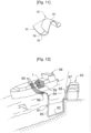
- a cutaway view of an LNG ship 58 shows a waterproof and thermally insulating tank 1 of generally prismatic shape mounted in the double hull 59 of the LNG ship 58.
- the tank wall 2 comprises a primary waterproof membrane 6 intended to be in contact with the LNG contained in the waterproof and thermally insulating tank 1, a secondary waterproof membrane 8 arranged between the primary waterproof membrane 6 and the double hull 59 of the LNG ship, and two thermally insulating barriers 7, 9 arranged respectively between the primary waterproof membrane 6 and the secondary waterproof membrane 8, and between the secondary waterproof membrane 8 and the double hull 59 of the LNG ship 58.
- loading/unloading pipes 60 arranged on the upper deck of the LNG ship 58 can be connected, by means of appropriate connectors, to a maritime or port terminal to transfer a cargo of liquefied gas, for example LNG , from or to the waterproof and thermally insulating tank 1.
- FIG. 12 also represents a maritime terminal comprising a loading and unloading station 61, an underwater pipeline 62 and a land installation 63.
- the loading and unloading station 61 is a fixed offshore installation comprising a movable arm 64 and a tower 65 which supports the movable arm 64.
- the movable arm 64 carries a bundle of insulated flexible pipes 66 which can connect to the loading pipes /unloading 60.
- the adjustable movable arm 64 adapts to all sizes of LNG ships 58.
- a connection pipe not shown extends inside the tower 65.
- the loading and unloading station 61 allows loading and the unloading of the LNG ship 58 from or to the onshore installation 63. This includes liquefied gas storage tanks 67 and connecting pipes 68 connected by the underwater pipe 62 to the loading and unloading station 61.
- the underwater pipe 62 allows the transfer of liquefied gas between the loading or unloading station 61 and the onshore installation 63 over a large distance, for example 5 km, which makes it possible to keep the LNG ship 58 at a long distance from the coast during loading and unloading operations.
- pumps are used on board the LNG ship 58 and/or pumps fitted to the on-shore installation 63 and/or pumps fitted to the loading and unloading station 61.
Landscapes
- Engineering & Computer Science (AREA)
- Mechanical Engineering (AREA)
- General Engineering & Computer Science (AREA)
- Chemical & Material Sciences (AREA)
- Combustion & Propulsion (AREA)
- Ocean & Marine Engineering (AREA)
- Physics & Mathematics (AREA)
- Thermal Sciences (AREA)
- Filling Or Discharging Of Gas Storage Vessels (AREA)
- Pens And Brushes (AREA)
- Catching Or Destruction (AREA)
Applications Claiming Priority (1)
| Application Number | Priority Date | Filing Date | Title |
|---|---|---|---|
| FR2203968A FR3135125B1 (fr) | 2022-04-27 | 2022-04-27 | Paroi de cuve comportant une conduite traversante |
Publications (1)
| Publication Number | Publication Date |
|---|---|
| EP4269863A1 true EP4269863A1 (fr) | 2023-11-01 |
Family
ID=82196431
Family Applications (1)
| Application Number | Title | Priority Date | Filing Date |
|---|---|---|---|
| EP23169330.0A Pending EP4269863A1 (fr) | 2022-04-27 | 2023-04-21 | Paroi de cuve comportant une conduite traversante |
Country Status (6)
| Country | Link |
|---|---|
| EP (1) | EP4269863A1 (https=) |
| JP (1) | JP2023163168A (https=) |
| KR (1) | KR20230152588A (https=) |
| CN (1) | CN116951302A (https=) |
| FR (1) | FR3135125B1 (https=) |
| TW (1) | TW202408878A (https=) |
Families Citing this family (7)
| Publication number | Priority date | Publication date | Assignee | Title |
|---|---|---|---|---|
| JP2021133198A (ja) * | 2020-02-28 | 2021-09-13 | 株式会社三洋物産 | 遊技機 |
| JP2021133200A (ja) * | 2020-02-28 | 2021-09-13 | 株式会社三洋物産 | 遊技機 |
| JP2021133199A (ja) * | 2020-02-28 | 2021-09-13 | 株式会社三洋物産 | 遊技機 |
| JP2021186294A (ja) * | 2020-05-29 | 2021-12-13 | 株式会社三洋物産 | 遊技機 |
| JP2022012089A (ja) * | 2020-06-30 | 2022-01-17 | 株式会社三洋物産 | 遊技機 |
| JP2022012088A (ja) * | 2020-06-30 | 2022-01-17 | 株式会社三洋物産 | 遊技機 |
| JP2022012090A (ja) * | 2020-06-30 | 2022-01-17 | 株式会社三洋物産 | 遊技機 |
Citations (8)
| Publication number | Priority date | Publication date | Assignee | Title |
|---|---|---|---|---|
| FR1376525A (fr) | 1963-06-11 | 1964-10-31 | Technigaz | Enceintes étanches aux gaz et aux liquides réalisées à partir d'une membrane souple disposée à l'intérieur d'une structure résistante |
| FR1379651A (fr) | 1963-06-27 | 1964-11-27 | Technigaz | Dispositif formant élément de paroi souple ou analogue et applications diverses dudit dispositif, en particulier à la construction de réservoirs ou analogues |
| FR1387955A (fr) | 1963-12-17 | 1965-02-05 | Technigaz | Procédé d'assemblage par soudure de tôles métalliques ondulées entrant dans la réalisation d'enceintes étanches et souples |
| FR2781557A1 (fr) | 1998-07-24 | 2000-01-28 | Gaz Transport & Technigaz | Perfectionnement pour une cuve etanche et thermiquement isolante a panneaux prefabriques |
| FR2861060A1 (fr) | 2003-10-16 | 2005-04-22 | Gaz Transport & Technigaz | Structure de paroi etanche et cuve munie d'une telle structure |
| FR2961580A1 (fr) | 2010-06-17 | 2011-12-23 | Gaztransp Et Technigaz | Cuve etanche et isolante comportant un pied de support |
| FR2984454A1 (fr) | 2011-12-20 | 2013-06-21 | Gaztransp Et Technigaz | Paroi de cuve comportant une conduite |
| WO2014128381A1 (fr) * | 2013-02-22 | 2014-08-28 | Gaztransport Et Technigaz | Paroi de cuve comportant un element traversant |
Family Cites Families (4)
| Publication number | Priority date | Publication date | Assignee | Title |
|---|---|---|---|---|
| FR3035175B1 (fr) * | 2015-04-20 | 2017-04-28 | Gaztransport Et Technigaz | Cuve etanche et thermiquement isolante equipee d'un element traversant |
| FR3068762B1 (fr) * | 2017-07-04 | 2019-08-09 | Gaztransport Et Technigaz | Cuve etanche et thermiquement isolante |
| KR102662431B1 (ko) * | 2019-01-29 | 2024-05-02 | 한화오션 주식회사 | 액화천연가스 저장탱크 |
| FR3094448B1 (fr) * | 2019-03-26 | 2022-06-17 | Gaztransport Et Technigaz | Cuve étanche et thermiquement isolante |
-
2022
- 2022-04-27 FR FR2203968A patent/FR3135125B1/fr active Active
-
2023
- 2023-04-21 EP EP23169330.0A patent/EP4269863A1/fr active Pending
- 2023-04-25 KR KR1020230053702A patent/KR20230152588A/ko not_active Ceased
- 2023-04-26 TW TW112115554A patent/TW202408878A/zh unknown
- 2023-04-26 JP JP2023072481A patent/JP2023163168A/ja active Pending
- 2023-04-27 CN CN202310473098.1A patent/CN116951302A/zh active Pending
Patent Citations (8)
| Publication number | Priority date | Publication date | Assignee | Title |
|---|---|---|---|---|
| FR1376525A (fr) | 1963-06-11 | 1964-10-31 | Technigaz | Enceintes étanches aux gaz et aux liquides réalisées à partir d'une membrane souple disposée à l'intérieur d'une structure résistante |
| FR1379651A (fr) | 1963-06-27 | 1964-11-27 | Technigaz | Dispositif formant élément de paroi souple ou analogue et applications diverses dudit dispositif, en particulier à la construction de réservoirs ou analogues |
| FR1387955A (fr) | 1963-12-17 | 1965-02-05 | Technigaz | Procédé d'assemblage par soudure de tôles métalliques ondulées entrant dans la réalisation d'enceintes étanches et souples |
| FR2781557A1 (fr) | 1998-07-24 | 2000-01-28 | Gaz Transport & Technigaz | Perfectionnement pour une cuve etanche et thermiquement isolante a panneaux prefabriques |
| FR2861060A1 (fr) | 2003-10-16 | 2005-04-22 | Gaz Transport & Technigaz | Structure de paroi etanche et cuve munie d'une telle structure |
| FR2961580A1 (fr) | 2010-06-17 | 2011-12-23 | Gaztransp Et Technigaz | Cuve etanche et isolante comportant un pied de support |
| FR2984454A1 (fr) | 2011-12-20 | 2013-06-21 | Gaztransp Et Technigaz | Paroi de cuve comportant une conduite |
| WO2014128381A1 (fr) * | 2013-02-22 | 2014-08-28 | Gaztransport Et Technigaz | Paroi de cuve comportant un element traversant |
Also Published As
| Publication number | Publication date |
|---|---|
| TW202408878A (zh) | 2024-03-01 |
| FR3135125B1 (fr) | 2024-08-09 |
| FR3135125A1 (fr) | 2023-11-03 |
| JP2023163168A (ja) | 2023-11-09 |
| CN116951302A (zh) | 2023-10-27 |
| KR20230152588A (ko) | 2023-11-03 |
Similar Documents
| Publication | Publication Date | Title |
|---|---|---|
| EP4269863A1 (fr) | Paroi de cuve comportant une conduite traversante | |
| EP2959206B1 (fr) | Paroi de cuve comportant un element traversant | |
| EP3362732B1 (fr) | Cuve étanche et thermiquement isolante | |
| EP3365592B1 (fr) | Cuve comprenant des blocs isolants de coin equipes de fentes de relaxation | |
| EP3198186B1 (fr) | Cuve étanche et isolante comportant un élément de pontage entre les panneaux de la barrière isolante secondaire | |
| EP3948060B1 (fr) | Cuve étanche et thermiquement isolante | |
| EP3473915B1 (fr) | Cuve etanche et thermiquement isolante | |
| WO2013093261A1 (fr) | Paroi de cuve comportant une conduite | |
| WO2019155154A1 (fr) | Installation pour le stockage et le transport d'un gaz liquefie | |
| EP2984383A2 (fr) | Cuve etanche et thermiquement isolante de stockage d'un fluide | |
| FR3082596A1 (fr) | Cuve etanche et thermiquement isolante a ondulations continues dans le dome liquide | |
| WO2012123656A1 (fr) | Bloc isolant pour la fabrication d'une paroi de cuve etanche | |
| WO2021186049A1 (fr) | Cuve étanche et thermiquement isolante | |
| WO2019239053A1 (fr) | Cuve etanche munie d'un element de jonction ondule | |
| WO2021140218A1 (fr) | Installation de stockage pour gaz liquéfié | |
| FR3143097A1 (fr) | Cuve étanche et thermiquement isolante | |
| FR3069903B1 (fr) | Cuve etanche et themiquement isolante | |
| EP3645933A1 (fr) | Membrane etanche et procede d'assemblage d'une membrane etanche | |
| WO2024125849A1 (fr) | Cuve étanche et thermiquement isolante comportant un élément traversant | |
| FR3093786A1 (fr) | Paroi de cuve comprenant une isolation améliorée autour d’une traversée | |
| WO2021233712A1 (fr) | Installation de stockage pour gaz liquéfié | |
| FR3135126A1 (fr) | Paroi de cuve traversée par une conduite étanche d’évacuation de fluide | |
| WO2024125850A1 (fr) | Cuve étanche et thermiquement isolante comportant un élément traversant | |
| WO2026032925A1 (fr) | Paroi pour cuve étanche et thermiquement isolante | |
| FR3165055A1 (fr) | Cuve étanche et thermiquement isolante comportant une structure d’angle |
Legal Events
| Date | Code | Title | Description |
|---|---|---|---|
| PUAI | Public reference made under article 153(3) epc to a published international application that has entered the european phase |
Free format text: ORIGINAL CODE: 0009012 |
|
| STAA | Information on the status of an ep patent application or granted ep patent |
Free format text: STATUS: REQUEST FOR EXAMINATION WAS MADE |
|
| 17P | Request for examination filed |
Effective date: 20230421 |
|
| AK | Designated contracting states |
Kind code of ref document: A1 Designated state(s): AL AT BE BG CH CY CZ DE DK EE ES FI FR GB GR HR HU IE IS IT LI LT LU LV MC ME MK MT NL NO PL PT RO RS SE SI SK SM TR |
|
| GRAP | Despatch of communication of intention to grant a patent |
Free format text: ORIGINAL CODE: EPIDOSNIGR1 |
|
| STAA | Information on the status of an ep patent application or granted ep patent |
Free format text: STATUS: GRANT OF PATENT IS INTENDED |