EP4269863A1 - Vessel wall having a through-duct - Google Patents
Vessel wall having a through-duct Download PDFInfo
- Publication number
- EP4269863A1 EP4269863A1 EP23169330.0A EP23169330A EP4269863A1 EP 4269863 A1 EP4269863 A1 EP 4269863A1 EP 23169330 A EP23169330 A EP 23169330A EP 4269863 A1 EP4269863 A1 EP 4269863A1
- Authority
- EP
- European Patent Office
- Prior art keywords
- thermally insulating
- waterproof
- primary
- tank
- pipe
- Prior art date
- Legal status (The legal status is an assumption and is not a legal conclusion. Google has not performed a legal analysis and makes no representation as to the accuracy of the status listed.)
- Pending
Links
- 239000012528 membrane Substances 0.000 claims abstract description 96
- 230000004888 barrier function Effects 0.000 claims abstract description 52
- 230000002093 peripheral effect Effects 0.000 claims description 53
- 238000003860 storage Methods 0.000 claims description 16
- 238000007667 floating Methods 0.000 claims description 12
- 238000004873 anchoring Methods 0.000 claims description 8
- 239000012530 fluid Substances 0.000 claims description 8
- 239000012263 liquid product Substances 0.000 claims description 8
- 239000007788 liquid Substances 0.000 claims description 6
- 238000012546 transfer Methods 0.000 claims description 5
- 239000012212 insulator Substances 0.000 claims description 4
- 238000004891 communication Methods 0.000 claims description 3
- 239000007789 gas Substances 0.000 description 27
- 239000003949 liquefied natural gas Substances 0.000 description 21
- 238000009434 installation Methods 0.000 description 11
- IJGRMHOSHXDMSA-UHFFFAOYSA-N Atomic nitrogen Chemical compound N#N IJGRMHOSHXDMSA-UHFFFAOYSA-N 0.000 description 8
- 238000009413 insulation Methods 0.000 description 7
- 229910052751 metal Inorganic materials 0.000 description 7
- 239000002184 metal Substances 0.000 description 6
- 239000000047 product Substances 0.000 description 6
- 238000003466 welding Methods 0.000 description 6
- 239000011261 inert gas Substances 0.000 description 5
- 229910001873 dinitrogen Inorganic materials 0.000 description 4
- 238000004519 manufacturing process Methods 0.000 description 4
- 238000007789 sealing Methods 0.000 description 4
- 230000008602 contraction Effects 0.000 description 3
- 230000008020 evaporation Effects 0.000 description 3
- 238000001704 evaporation Methods 0.000 description 3
- 229920005830 Polyurethane Foam Polymers 0.000 description 2
- 239000011324 bead Substances 0.000 description 2
- 239000002131 composite material Substances 0.000 description 2
- 239000006260 foam Substances 0.000 description 2
- 239000011521 glass Substances 0.000 description 2
- 239000003365 glass fiber Substances 0.000 description 2
- 239000011491 glass wool Substances 0.000 description 2
- 229910052757 nitrogen Inorganic materials 0.000 description 2
- 230000036961 partial effect Effects 0.000 description 2
- 239000011496 polyurethane foam Substances 0.000 description 2
- 230000000284 resting effect Effects 0.000 description 2
- 229910001220 stainless steel Inorganic materials 0.000 description 2
- 239000010935 stainless steel Substances 0.000 description 2
- 210000002268 wool Anatomy 0.000 description 2
- 240000008042 Zea mays Species 0.000 description 1
- 238000004026 adhesive bonding Methods 0.000 description 1
- 238000009530 blood pressure measurement Methods 0.000 description 1
- 230000015556 catabolic process Effects 0.000 description 1
- 239000000470 constituent Substances 0.000 description 1
- 238000010276 construction Methods 0.000 description 1
- 230000001186 cumulative effect Effects 0.000 description 1
- 238000005520 cutting process Methods 0.000 description 1
- 238000006731 degradation reaction Methods 0.000 description 1
- 230000000694 effects Effects 0.000 description 1
- 238000005516 engineering process Methods 0.000 description 1
- 239000000284 extract Substances 0.000 description 1
- 230000005484 gravity Effects 0.000 description 1
- 239000003779 heat-resistant material Substances 0.000 description 1
- 230000002706 hydrostatic effect Effects 0.000 description 1
- 239000012774 insulation material Substances 0.000 description 1
- 239000013521 mastic Substances 0.000 description 1
- 238000000034 method Methods 0.000 description 1
- 238000005457 optimization Methods 0.000 description 1
- 239000011120 plywood Substances 0.000 description 1
- 229920002635 polyurethane Polymers 0.000 description 1
- 239000004814 polyurethane Substances 0.000 description 1
- 238000012545 processing Methods 0.000 description 1
- 230000001681 protective effect Effects 0.000 description 1
- 230000002829 reductive effect Effects 0.000 description 1
- 239000011347 resin Substances 0.000 description 1
- 229920005989 resin Polymers 0.000 description 1
- 230000003068 static effect Effects 0.000 description 1
- XLYOFNOQVPJJNP-UHFFFAOYSA-N water Substances O XLYOFNOQVPJJNP-UHFFFAOYSA-N 0.000 description 1
- 238000004078 waterproofing Methods 0.000 description 1
- 238000005493 welding type Methods 0.000 description 1
Images


Classifications
-
- F—MECHANICAL ENGINEERING; LIGHTING; HEATING; WEAPONS; BLASTING
- F17—STORING OR DISTRIBUTING GASES OR LIQUIDS
- F17C—VESSELS FOR CONTAINING OR STORING COMPRESSED, LIQUEFIED OR SOLIDIFIED GASES; FIXED-CAPACITY GAS-HOLDERS; FILLING VESSELS WITH, OR DISCHARGING FROM VESSELS, COMPRESSED, LIQUEFIED, OR SOLIDIFIED GASES
- F17C13/00—Details of vessels or of the filling or discharging of vessels
- F17C13/004—Details of vessels or of the filling or discharging of vessels for large storage vessels not under pressure
-
- F—MECHANICAL ENGINEERING; LIGHTING; HEATING; WEAPONS; BLASTING
- F17—STORING OR DISTRIBUTING GASES OR LIQUIDS
- F17C—VESSELS FOR CONTAINING OR STORING COMPRESSED, LIQUEFIED OR SOLIDIFIED GASES; FIXED-CAPACITY GAS-HOLDERS; FILLING VESSELS WITH, OR DISCHARGING FROM VESSELS, COMPRESSED, LIQUEFIED, OR SOLIDIFIED GASES
- F17C3/00—Vessels not under pressure
- F17C3/02—Vessels not under pressure with provision for thermal insulation
- F17C3/025—Bulk storage in barges or on ships
-
- B—PERFORMING OPERATIONS; TRANSPORTING
- B63—SHIPS OR OTHER WATERBORNE VESSELS; RELATED EQUIPMENT
- B63B—SHIPS OR OTHER WATERBORNE VESSELS; EQUIPMENT FOR SHIPPING
- B63B25/00—Load-accommodating arrangements, e.g. stowing, trimming; Vessels characterised thereby
- B63B25/02—Load-accommodating arrangements, e.g. stowing, trimming; Vessels characterised thereby for bulk goods
- B63B25/08—Load-accommodating arrangements, e.g. stowing, trimming; Vessels characterised thereby for bulk goods fluid
- B63B25/12—Load-accommodating arrangements, e.g. stowing, trimming; Vessels characterised thereby for bulk goods fluid closed
- B63B25/16—Load-accommodating arrangements, e.g. stowing, trimming; Vessels characterised thereby for bulk goods fluid closed heat-insulated
-
- B—PERFORMING OPERATIONS; TRANSPORTING
- B63—SHIPS OR OTHER WATERBORNE VESSELS; RELATED EQUIPMENT
- B63B—SHIPS OR OTHER WATERBORNE VESSELS; EQUIPMENT FOR SHIPPING
- B63B27/00—Arrangement of ship-based loading or unloading equipment for cargo or passengers
- B63B27/24—Arrangement of ship-based loading or unloading equipment for cargo or passengers of pipe-lines
-
- B—PERFORMING OPERATIONS; TRANSPORTING
- B63—SHIPS OR OTHER WATERBORNE VESSELS; RELATED EQUIPMENT
- B63B—SHIPS OR OTHER WATERBORNE VESSELS; EQUIPMENT FOR SHIPPING
- B63B27/00—Arrangement of ship-based loading or unloading equipment for cargo or passengers
- B63B27/30—Arrangement of ship-based loading or unloading equipment for transfer at sea between ships or between ships and off-shore structures
- B63B27/34—Arrangement of ship-based loading or unloading equipment for transfer at sea between ships or between ships and off-shore structures using pipe-lines
-
- F—MECHANICAL ENGINEERING; LIGHTING; HEATING; WEAPONS; BLASTING
- F17—STORING OR DISTRIBUTING GASES OR LIQUIDS
- F17C—VESSELS FOR CONTAINING OR STORING COMPRESSED, LIQUEFIED OR SOLIDIFIED GASES; FIXED-CAPACITY GAS-HOLDERS; FILLING VESSELS WITH, OR DISCHARGING FROM VESSELS, COMPRESSED, LIQUEFIED, OR SOLIDIFIED GASES
- F17C13/00—Details of vessels or of the filling or discharging of vessels
-
- F—MECHANICAL ENGINEERING; LIGHTING; HEATING; WEAPONS; BLASTING
- F17—STORING OR DISTRIBUTING GASES OR LIQUIDS
- F17C—VESSELS FOR CONTAINING OR STORING COMPRESSED, LIQUEFIED OR SOLIDIFIED GASES; FIXED-CAPACITY GAS-HOLDERS; FILLING VESSELS WITH, OR DISCHARGING FROM VESSELS, COMPRESSED, LIQUEFIED, OR SOLIDIFIED GASES
- F17C3/00—Vessels not under pressure
- F17C3/02—Vessels not under pressure with provision for thermal insulation
- F17C3/025—Bulk storage in barges or on ships
- F17C3/027—Wallpanels for so-called membrane tanks
-
- F—MECHANICAL ENGINEERING; LIGHTING; HEATING; WEAPONS; BLASTING
- F17—STORING OR DISTRIBUTING GASES OR LIQUIDS
- F17C—VESSELS FOR CONTAINING OR STORING COMPRESSED, LIQUEFIED OR SOLIDIFIED GASES; FIXED-CAPACITY GAS-HOLDERS; FILLING VESSELS WITH, OR DISCHARGING FROM VESSELS, COMPRESSED, LIQUEFIED, OR SOLIDIFIED GASES
- F17C3/00—Vessels not under pressure
- F17C3/02—Vessels not under pressure with provision for thermal insulation
- F17C3/04—Vessels not under pressure with provision for thermal insulation by insulating layers
-
- F—MECHANICAL ENGINEERING; LIGHTING; HEATING; WEAPONS; BLASTING
- F17—STORING OR DISTRIBUTING GASES OR LIQUIDS
- F17C—VESSELS FOR CONTAINING OR STORING COMPRESSED, LIQUEFIED OR SOLIDIFIED GASES; FIXED-CAPACITY GAS-HOLDERS; FILLING VESSELS WITH, OR DISCHARGING FROM VESSELS, COMPRESSED, LIQUEFIED, OR SOLIDIFIED GASES
- F17C6/00—Methods and apparatus for filling vessels not under pressure with liquefied or solidified gases
-
- F—MECHANICAL ENGINEERING; LIGHTING; HEATING; WEAPONS; BLASTING
- F17—STORING OR DISTRIBUTING GASES OR LIQUIDS
- F17C—VESSELS FOR CONTAINING OR STORING COMPRESSED, LIQUEFIED OR SOLIDIFIED GASES; FIXED-CAPACITY GAS-HOLDERS; FILLING VESSELS WITH, OR DISCHARGING FROM VESSELS, COMPRESSED, LIQUEFIED, OR SOLIDIFIED GASES
- F17C9/00—Methods or apparatus for discharging liquefied or solidified gases from vessels not under pressure
-
- F—MECHANICAL ENGINEERING; LIGHTING; HEATING; WEAPONS; BLASTING
- F17—STORING OR DISTRIBUTING GASES OR LIQUIDS
- F17C—VESSELS FOR CONTAINING OR STORING COMPRESSED, LIQUEFIED OR SOLIDIFIED GASES; FIXED-CAPACITY GAS-HOLDERS; FILLING VESSELS WITH, OR DISCHARGING FROM VESSELS, COMPRESSED, LIQUEFIED, OR SOLIDIFIED GASES
- F17C2201/00—Vessel construction, in particular geometry, arrangement or size
- F17C2201/01—Shape
- F17C2201/0147—Shape complex
- F17C2201/0157—Polygonal
-
- F—MECHANICAL ENGINEERING; LIGHTING; HEATING; WEAPONS; BLASTING
- F17—STORING OR DISTRIBUTING GASES OR LIQUIDS
- F17C—VESSELS FOR CONTAINING OR STORING COMPRESSED, LIQUEFIED OR SOLIDIFIED GASES; FIXED-CAPACITY GAS-HOLDERS; FILLING VESSELS WITH, OR DISCHARGING FROM VESSELS, COMPRESSED, LIQUEFIED, OR SOLIDIFIED GASES
- F17C2201/00—Vessel construction, in particular geometry, arrangement or size
- F17C2201/05—Size
- F17C2201/052—Size large (>1000 m3)
-
- F—MECHANICAL ENGINEERING; LIGHTING; HEATING; WEAPONS; BLASTING
- F17—STORING OR DISTRIBUTING GASES OR LIQUIDS
- F17C—VESSELS FOR CONTAINING OR STORING COMPRESSED, LIQUEFIED OR SOLIDIFIED GASES; FIXED-CAPACITY GAS-HOLDERS; FILLING VESSELS WITH, OR DISCHARGING FROM VESSELS, COMPRESSED, LIQUEFIED, OR SOLIDIFIED GASES
- F17C2203/00—Vessel construction, in particular walls or details thereof
- F17C2203/03—Thermal insulations
- F17C2203/0304—Thermal insulations by solid means
- F17C2203/0358—Thermal insulations by solid means in form of panels
-
- F—MECHANICAL ENGINEERING; LIGHTING; HEATING; WEAPONS; BLASTING
- F17—STORING OR DISTRIBUTING GASES OR LIQUIDS
- F17C—VESSELS FOR CONTAINING OR STORING COMPRESSED, LIQUEFIED OR SOLIDIFIED GASES; FIXED-CAPACITY GAS-HOLDERS; FILLING VESSELS WITH, OR DISCHARGING FROM VESSELS, COMPRESSED, LIQUEFIED, OR SOLIDIFIED GASES
- F17C2203/00—Vessel construction, in particular walls or details thereof
- F17C2203/03—Thermal insulations
- F17C2203/0375—Thermal insulations by gas
- F17C2203/0379—Inert
-
- F—MECHANICAL ENGINEERING; LIGHTING; HEATING; WEAPONS; BLASTING
- F17—STORING OR DISTRIBUTING GASES OR LIQUIDS
- F17C—VESSELS FOR CONTAINING OR STORING COMPRESSED, LIQUEFIED OR SOLIDIFIED GASES; FIXED-CAPACITY GAS-HOLDERS; FILLING VESSELS WITH, OR DISCHARGING FROM VESSELS, COMPRESSED, LIQUEFIED, OR SOLIDIFIED GASES
- F17C2205/00—Vessel construction, in particular mounting arrangements, attachments or identifications means
- F17C2205/03—Fluid connections, filters, valves, closure means or other attachments
- F17C2205/0302—Fittings, valves, filters, or components in connection with the gas storage device
-
- F—MECHANICAL ENGINEERING; LIGHTING; HEATING; WEAPONS; BLASTING
- F17—STORING OR DISTRIBUTING GASES OR LIQUIDS
- F17C—VESSELS FOR CONTAINING OR STORING COMPRESSED, LIQUEFIED OR SOLIDIFIED GASES; FIXED-CAPACITY GAS-HOLDERS; FILLING VESSELS WITH, OR DISCHARGING FROM VESSELS, COMPRESSED, LIQUEFIED, OR SOLIDIFIED GASES
- F17C2221/00—Handled fluid, in particular type of fluid
- F17C2221/03—Mixtures
- F17C2221/032—Hydrocarbons
- F17C2221/033—Methane, e.g. natural gas, CNG, LNG, GNL, GNC, PLNG
-
- F—MECHANICAL ENGINEERING; LIGHTING; HEATING; WEAPONS; BLASTING
- F17—STORING OR DISTRIBUTING GASES OR LIQUIDS
- F17C—VESSELS FOR CONTAINING OR STORING COMPRESSED, LIQUEFIED OR SOLIDIFIED GASES; FIXED-CAPACITY GAS-HOLDERS; FILLING VESSELS WITH, OR DISCHARGING FROM VESSELS, COMPRESSED, LIQUEFIED, OR SOLIDIFIED GASES
- F17C2223/00—Handled fluid before transfer, i.e. state of fluid when stored in the vessel or before transfer from the vessel
- F17C2223/01—Handled fluid before transfer, i.e. state of fluid when stored in the vessel or before transfer from the vessel characterised by the phase
- F17C2223/0146—Two-phase
- F17C2223/0153—Liquefied gas, e.g. LPG, GPL
- F17C2223/0161—Liquefied gas, e.g. LPG, GPL cryogenic, e.g. LNG, GNL, PLNG
-
- F—MECHANICAL ENGINEERING; LIGHTING; HEATING; WEAPONS; BLASTING
- F17—STORING OR DISTRIBUTING GASES OR LIQUIDS
- F17C—VESSELS FOR CONTAINING OR STORING COMPRESSED, LIQUEFIED OR SOLIDIFIED GASES; FIXED-CAPACITY GAS-HOLDERS; FILLING VESSELS WITH, OR DISCHARGING FROM VESSELS, COMPRESSED, LIQUEFIED, OR SOLIDIFIED GASES
- F17C2223/00—Handled fluid before transfer, i.e. state of fluid when stored in the vessel or before transfer from the vessel
- F17C2223/03—Handled fluid before transfer, i.e. state of fluid when stored in the vessel or before transfer from the vessel characterised by the pressure level
- F17C2223/033—Small pressure, e.g. for liquefied gas
-
- F—MECHANICAL ENGINEERING; LIGHTING; HEATING; WEAPONS; BLASTING
- F17—STORING OR DISTRIBUTING GASES OR LIQUIDS
- F17C—VESSELS FOR CONTAINING OR STORING COMPRESSED, LIQUEFIED OR SOLIDIFIED GASES; FIXED-CAPACITY GAS-HOLDERS; FILLING VESSELS WITH, OR DISCHARGING FROM VESSELS, COMPRESSED, LIQUEFIED, OR SOLIDIFIED GASES
- F17C2223/00—Handled fluid before transfer, i.e. state of fluid when stored in the vessel or before transfer from the vessel
- F17C2223/04—Handled fluid before transfer, i.e. state of fluid when stored in the vessel or before transfer from the vessel characterised by other properties of handled fluid before transfer
- F17C2223/042—Localisation of the removal point
- F17C2223/043—Localisation of the removal point in the gas
-
- F—MECHANICAL ENGINEERING; LIGHTING; HEATING; WEAPONS; BLASTING
- F17—STORING OR DISTRIBUTING GASES OR LIQUIDS
- F17C—VESSELS FOR CONTAINING OR STORING COMPRESSED, LIQUEFIED OR SOLIDIFIED GASES; FIXED-CAPACITY GAS-HOLDERS; FILLING VESSELS WITH, OR DISCHARGING FROM VESSELS, COMPRESSED, LIQUEFIED, OR SOLIDIFIED GASES
- F17C2227/00—Transfer of fluids, i.e. method or means for transferring the fluid; Heat exchange with the fluid
- F17C2227/01—Propulsion of the fluid
- F17C2227/0128—Propulsion of the fluid with pumps or compressors
- F17C2227/0135—Pumps
-
- F—MECHANICAL ENGINEERING; LIGHTING; HEATING; WEAPONS; BLASTING
- F17—STORING OR DISTRIBUTING GASES OR LIQUIDS
- F17C—VESSELS FOR CONTAINING OR STORING COMPRESSED, LIQUEFIED OR SOLIDIFIED GASES; FIXED-CAPACITY GAS-HOLDERS; FILLING VESSELS WITH, OR DISCHARGING FROM VESSELS, COMPRESSED, LIQUEFIED, OR SOLIDIFIED GASES
- F17C2260/00—Purposes of gas storage and gas handling
- F17C2260/01—Improving mechanical properties or manufacturing
- F17C2260/011—Improving strength
-
- F—MECHANICAL ENGINEERING; LIGHTING; HEATING; WEAPONS; BLASTING
- F17—STORING OR DISTRIBUTING GASES OR LIQUIDS
- F17C—VESSELS FOR CONTAINING OR STORING COMPRESSED, LIQUEFIED OR SOLIDIFIED GASES; FIXED-CAPACITY GAS-HOLDERS; FILLING VESSELS WITH, OR DISCHARGING FROM VESSELS, COMPRESSED, LIQUEFIED, OR SOLIDIFIED GASES
- F17C2270/00—Applications
- F17C2270/01—Applications for fluid transport or storage
- F17C2270/0102—Applications for fluid transport or storage on or in the water
- F17C2270/0105—Ships
- F17C2270/0107—Wall panels
Definitions
- the invention relates to the field of manufacturing waterproof and thermally insulating tanks.
- the present invention relates to tanks intended to contain cold or hot liquids, and more particularly tanks for the storage and/or transport of liquefied gas by sea arranged in a supporting structure.
- Airtight and thermally insulating tanks can be used in different industries to store a hot or cold product.
- a product may be liquefied natural gas (LNG).
- LNG is a liquid that can be stored at atmospheric pressure at around -163°C in land-based storage tanks or in tanks on board floating structures.
- floating structures are in particular barges, LNG ships for transporting the product and off-shore installations, known in particular by the acronyms FPSO and FSRU, for the storage, liquefaction or regasification of the product.
- waterproof and thermally insulating tanks are made up of one or more waterproof membranes associated with insulating layers.
- a waterproof and thermally insulating tank comprising a tank wall fixed to a supporting structure, in which the tank wall has a multilayer structure which successively comprises a primary waterproof membrane intended to be in contact with the product contained in the tank, a barrier primary thermally insulating, a secondary waterproof membrane and a secondary thermally insulating barrier.
- the waterproof membranes have sufficient elasticity to resist forces resulting for example from hydrostatic pressure, dynamic pressure in the event of movement of the cargo, and/or temperature variations.
- such waterproof membranes and the underlying thermal insulation material are relatively fragile and cannot necessarily support the weight of a mat such as that for loading/unloading LNG tanks.
- a support foot can be provided as in FR-A-2961580 .
- thermodynamic conditions of the sealed and thermally insulating tanks during the storage of such a liquid lead to the evaporation of a certain quantity of vapor which causes the internal pressure of the tanks to vary.
- the evaporation gases are collected and sent to an evaporation collector to be, for example, reliquefied or burned in the propulsion engine of a ship.
- a collector pipe can be provided as in FR-A-2984454 .
- An idea underlying the invention is to reinforce the fatigue resistance of the tank wall in the area around which the through pipe passes through the multilayer structure.
- such a waterproof and thermally insulating tank may include one or more of the following characteristics.
- the waterproof layer is a first waterproof layer covering the secondary thermally insulating blocks and in which said tank wall comprises a second waterproof layer fixed in a sealed manner astride the first waterproof layer and on the interior surface of the plate waterproof around the through pipe, the second waterproof layer extending the secondary waterproof membrane to the waterproof plate.
- the second waterproof sheet comprises at least two waterproof strips, each waterproof strip being arranged astride two adjacent secondary thermally insulating blocks.
- the second waterproof sheet comprises two waterproof strips located in the extension of one another, on either side of the through pipe so as to cover the chimney.
- the two waterproof strips of the second waterproof layer are positioned perpendicular to said at least interface portion of the first primary thermally insulating block and said at least one interface portion of the second primary thermally insulating block.
- the tank wall comprises two prefabricated panels arranged on either side of the through pipe, each of the prefabricated panels comprising a lower thermally insulating block constituting a said thermally secondary block, the first waterproof layer covering the block secondary thermally insulating layer, and an upper thermally insulating block arranged on a central zone of the first waterproof layer and the thermally insulating block lower without covering a peripheral zone of the first waterproof layer, the upper thermally insulating block forming part of the primary thermally insulating barrier, said primary thermally insulating blocks being arranged between the upper thermally insulating blocks of the two prefabricated panels on said peripheral zone of the first waterproof layer of the two prefabricated panels and on said chimney.
- the primary waterproof membrane comprises waterproof plates connected together in a watertight manner at the edges of the waterproof plates, and the upper thermally insulating blocks of the two prefabricated panels carry anchoring strips to the right of said edges of the plates. waterproof to anchor the waterproof plates to said prefabricated panels, the primary thermally insulating blocks comprising thermal protection strips at the right of said edges of the waterproof plates so that the waterproof plates are not anchored to said primary thermally insulating blocks.
- the primary waterproof membrane comprises at least one series of corrugations comprising corrugations extending along direction lines parallel to each other, said corrugations projecting towards the interior of said waterproof and thermally insulating tank, and in which a window interrupts at least one direction line of an undulation of said series of undulations, said corrugation preferably having an open end at the window, said sealed and thermally insulating tank comprising at least one end piece to close the open end of said at least one corrugation.
- the window interrupts at least two undulation guidelines of said at least one series of undulations, and the through pipe is centered at a position located between two of said interrupted undulation guidelines.
- the primary waterproof membrane comprises a first series of undulations and a second series of undulations secant to the first series of undulations, the window interrupts at least two direction lines of the undulations of the first series of undulations and at least two direction lines of the undulations of the second series of undulations, and the through pipe is centered at a position located between two direction lines of the interrupted undulations of said first series of undulations and two direction lines of the interrupted undulations of said second series of undulations.
- the direction lines of the undulations of the first series of undulations are perpendicular to the direction lines of the undulations of the second series of undulations.
- the aforementioned window can have different shapes, in particular depending on the shape of the through pipe and/or the shape of the constituent elements of the primary waterproof membrane.
- the window is a quadrilateral having two sides parallel to the direction lines of the undulations of the first series of undulations and two sides parallel to the direction lines of the undulations of the second series of undulations.
- the window can be a square, a rectangle or a parallelogram.
- the through pipe has a circular section and crosses the window in its center.
- the external pipe comprises a first peripheral connection plate and a second peripheral connection plate, the second peripheral connection plate being fixed in a sealed manner to the first peripheral connection plate all around said first connection plate peripheral, the first peripheral connecting plate extending parallel to the through pipe towards the outside of said sealed and thermally insulating tank from the second peripheral connecting plate, said second peripheral connecting plate being fixed in a sealed manner to the sealed plate and projecting towards the supporting structure parallel to the through pipe.
- the tank wall further comprises, around the through pipe, at least one closure plate arranged on the primary thermally insulating blocks and sealed in a sealed manner to the through pipe.
- the closure plate consists of a single piece metal plate surrounding the through pipe.
- At least one of said primary thermally insulating blocks comprises at least one groove
- the closing plate comprises at least one groove covered by one of said end pieces and superimposed on said groove of the thermally insulating block primary so as to allow the circulation of an inerting gas between the corrugation and the external pipe.
- the tank wall comprises a thermal protection sheet interposed between the primary thermally insulating blocks and the closure plate.
- the thermally protective sheet is filmed in one piece around the through pipe.
- the thermal protection sheet comprises at least one groove superimposed on one said groove of the primary thermally insulating block and positioned under one said groove of the closing plate.
- the through pipe defines a passage between the interior of the sealed and thermally insulating tank and a steam collector arranged outside of said sealed and thermally insulating tank.
- Such a tank can be part of a land storage installation, for example to store liquefied gas or be installed in a floating, coastal or deep water structure, in particular an LNG ship, an LPG transport ship, a floating unit storage and regasification unit (FSRU), a floating production and remote storage unit (FPSO) and others.
- a floating unit storage and regasification unit FSRU
- FPSO floating production and remote storage unit
- the invention also provides a ship for transporting a cold liquid product, the ship comprising a double hull and a waterproof and thermally insulating tank placed in the double hull.
- the invention also provides the use of a vessel for loading or unloading a cold liquid product, in which a cold liquid product is conveyed through insulated pipes from or to a processing installation. floating or land storage to or from the ship's watertight and thermally insulating tank.
- the invention also provides a transfer system for a cold liquid, the system comprising a ship, insulated pipes arranged so as to connect the waterproof and thermally insulating tank installed in the hull of the ship to an installation of floating or land-based storage facility and a pump for driving a flow of cold liquid product through the insulated pipelines to or from the floating or land-based storage facility to or from the vessel's sealed and thermally insulated tank.
- a waterproof and thermally insulating tank 1 comprises tank walls 2 fixed to the interior surface of corresponding walls of a supporting structure 3.
- the supporting structure 3 is for example the inner shell of a double-hulled vessel or construction located on land.
- There figure 1 is a partial of the waterproof and thermally insulating tank 1 showing only a ceiling wall.
- the terms “on”, “above”, “superior” and “top” generally refer to a position located towards the inside of the waterproof and thermally insulating tank 1 while the terms “under”, “ below”, “lower” and “bottom” generally refer to a position located towards the outside of the sealed and thermally insulating tank 1, regardless of the orientation of the tank wall 2 in relation to the gravity field earthly.
- the waterproof and thermally insulating tank 1 can be produced according to different geometries, for example a prismatic geometry in the hull of a ship or a cylindrical geometry on land or other.
- a waterproof and thermally insulating tank 1 intended for the storage and/or transport of liquefied natural gas by sea.
- a waterproof and thermally insulating tank 1 can be a tank used for the land storage of other cold or hot products.
- THE figures 1 And 2 present a fluid collection device 4.
- a fluid collection device 4 comprises a through pipe 5 passing through a tank wall 2, for example the ceiling wall of the sealed and thermally insulating tank 1.
- the tank wall 2 presents, successively, in a thickness direction, from the inside of the sealed and thermally insulating tank 1 towards the supporting structure 3, a primary sealing membrane 6 in contact with the liquefied gas, a primary thermally insulating barrier 7, a secondary waterproof membrane 8 and a secondary thermally insulating barrier 9.
- the primary thermally insulating barrier 7, the secondary waterproof membrane 8 and the secondary thermally insulating barrier 9 are essentially constituted by a set of prefabricated panels resting on beads of putty 11 and fixed to the supporting structure 3.
- the fluid collection device 4 comprises a barrel 12 which extends outside the supporting structure 3, as well as the through pipe 5, anchored inside the barrel 12.
- the barrel 12 and the through pipe 5 have here a cylindrical shape of revolution with a circular section. However, other forms can be considered.
- the supporting structure 3 has a circular opening 13.
- the barrel 12 is welded around the circular opening 13.
- the through pipe 5 passes through the tank wall 2 at the center of the circular opening 13.
- the through pipe 5 passes through the membranes primary 6 and secondary 8 waterproof barriers, and the primary 7 and secondary 9 thermally insulating barriers, to open inside the sealed and thermally insulating tank 1.
- the through pipe 5 is in particular connected to a steam collector outside of the sealed and thermally insulating tank which extracts this vapor and transmits it for example to the ship's propulsion device to power the ship's propulsion or to a liquefaction device to then reintroduce the liquefied gas into the tank.
- the primary waterproof membrane 6 is connected in a sealed manner to the through pipe 5.
- the secondary waterproof membrane 8 is also connected in a sealed manner to the through pipe 5 except in a passage allowing a gas phase present between the primary waterproof membrane 6 and the secondary waterproof membrane 8 to circulate towards two secondary pipes 14, 15.
- the gas phase is typically dinitrogen or another inerting gas. In this way, the space between the primary waterproof membrane 6 and the secondary waterproof membrane 8 forms a primary sealed space connected to the two secondary pipes 14, 15.
- the barrel 12 is connected in a sealed manner to the supporting structure 3.
- a layer of insulation 16 is uniformly distributed over the outer span of the through pipe 5 which has a diameter smaller than the circular opening 13.
- gas phase is typically dinitrogen or another inerting gas.
- the intermediate space and the space between the supporting structure 3 and the secondary thermally insulating barrier 9 thus form a secondary sealed space.
- the two secondary pipes 14, 15 extend parallel to the through pipe 5 in the insulation layer 16, from the exterior of the barrel 12 to the primary sealed space.
- the first secondary pipe 14 makes it possible to create a passage between the primary sealed space and an evacuation member not shown which makes it possible to control the gas phase present in the primary space.
- the second secondary pipe 15 makes it possible to create a passage between the primary space and a pressure measuring member not shown.
- Two other pipes not shown are welded to the barrel 12 and open inside the barrel 12 in the secondary sealed space to also allow the management of the gas phase and pressure measurement in the secondary sealed space.
- the pipes connected to the secondary sealed space also allow scanning with an inert gas, for example nitrogen scanning, in the secondary sealed space.
- the prefabricated panel 10a, 10b comprises a secondary thermally insulating block 17 anchored against the supporting structure 3.
- the secondary thermally insulating block 17 comprises a rigid lower panel 18 supported by the beads of mastic 11 and a layer of thermal insulation 19 in foam polyurethane.
- a first waterproof sheet 20 of composite material comprising for example a metal sheet and sheets of glass fibers embedded in a resin adheres over the entire surface of the thermal insulating layer 19 of the secondary thermally insulating block 17.
- the first waterproof sheet 20 constitutes an element of the secondary waterproof membrane 8.
- the prefabricated panel 10a, 10b also includes an upper thermally insulating block 21a, 21b.
- the upper thermally insulating block 21a, 21b comprises a thermal insulating layer 22 of polyurethane foam which partially covers the first waterproof layer 20 and adheres to it.
- a rigid upper panel 23 covers the thermal insulating layer 22 and constitutes with it an element of the primary thermally insulating barrier 7.
- the through pipe 5 passes through the circular opening 13, the secondary thermally insulating barrier 9, the secondary waterproof membrane 8, the primary thermally insulating barrier 7 and the primary waterproof membrane 6.
- a closing plate 24 of circular shape extends around the through pipe 5 in an area located beyond the supporting structure 3.
- the closing plate 24 has an upper surface parallel to the tank wall 2 to which the insulation layer 16 which surrounds the pipe is glued through 5.
- This closing plate 24 also includes two orifices 25, 26 to which the two secondary pipes 14, 15 are welded.
- the seal between the secondary thermally insulating barrier 9 and the through pipe 5 is achieved via the shutter plate 24, a first peripheral connection plate 27, a second peripheral connection plate 28 and of a sealed plate 29.
- the first peripheral connecting plate 27, of tubular shape is fixed in a sealed manner over its entire periphery on the shutter plate 24 and extends parallel to the through pipe 5 towards the interior of the waterproof and thermally insulating tank 1 to form an external pipe.
- the second peripheral connecting plate 28 also of tubular shape, to the sealed plate 29 of circular shape.
- the closing plate 24, the sealed plate 29 and the peripheral connection plates 27, 28 form an internal space 30 of the external pipe, leaning against the external wall of the through pipe 5.
- a second waterproof layer 31 is fixed in a watertight manner astride the first waterproof sheet 20 and the waterproof plate 29 to seal the secondary waterproof membrane 8.
- the sealed plate 29 comprises a circular passage 32 crossed by the through pipe 5.
- This circular passage 32 has a diameter greater than the diameter of the through pipe 5 so as to leave a spacing between the sealed plate 29 and the through pipe 5. Thanks to this spacing, the gas phase can circulate from the primary sealed space located between the primary sealed member 6 and the secondary sealed membrane 8 towards the internal space 30.
- the two secondary pipes 14, 15 are connected in a sealed manner to the shutter plate 24.
- This architecture makes it possible to carry out scanning with an inert gas.
- the internal space 30 is filled with an insulator permeable to vapors or gases.
- the second peripheral connecting plate 28 of tubular shape is welded to the lower surface of the sealed plate 29.
- the interior surface of the second peripheral connecting plate 28 has a diameter substantially equal to the external diameter of the first peripheral connecting plate 27.
- the peripheral connecting plates 27, 28 can fit together and cooperate to slide when they are not welded.
- the spacing between the sealed plate 29 and the supporting structure 3 can be adjusted to place the sealed plate 29 precisely at the level of the membrane secondary seal 8.
- the interlocking of the first peripheral connecting plate 27 with the second peripheral connecting plate 28 allows the centering of the through pipe 5 relative to the opening 13, as well as the orientation of the sealed plate 29.
- the welds between the shutter plate 24 and the first peripheral connection plate 27, between the first peripheral connection plate 27 and the second peripheral connection plate 28, and between the second peripheral connection plate 28 and the sealed plate 29 are made so as to obtain sealing between these elements.
- the shutter plate 24, the sealed plate 29, the first peripheral connection plate 27 and the second peripheral connection plate 28 are metallic elements, for example made of stainless steel.
- the anchoring of the through pipe is made in a part 33 of the through pipe spaced in an opposite direction inside the sealed and thermally insulating tank 1 relative to the supporting structure 3.
- This anchoring comprises a frustoconical metal element 34 extending inside the barrel 12.
- fins 40 are arranged regularly inside the internal space 30 between the through pipe 5 and the first peripheral connection plate 27 in order to position and fix the first peripheral connection plate 27 relative to the through pipe 5 .
- two primary thermally insulating blocks 35 are placed astride the secondary thermally insulating blocks 17 of the prefabricated panels 10a, 10b and on the waterproof plate 29 to form the primary thermally insulating barrier 7 between the through pipe 5 and the prefabricated panels 10a, 10b .
- the primary thermally insulating block 35 comprises, like the upper thermally insulating block 21a, 21b, an insulating layer 36 resting on the secondary thermally insulating barrier 9.
- the insulating layer 36 is surmounted by an upper panel 37.
- the upper thermally insulating blocks 21a, 21b of the prefabricated panels 10a, 10b and the primary thermally insulating blocks 35 support the primary waterproof membrane 6 produced in the form of metal plates having undulations 38a, 38b. These undulations 38a, 38b form elastic zones to absorb thermal contraction and static and dynamic pressure forces.
- Such sealing barriers made of corrugated or embossed sheet metal have in particular been described in FR-A-1379651 , FR-A-1376525 , FR-A-2781557 And FR-A-2861060 .
- the primary waterproof membrane 6 is connected in a sealed manner to the through pipe 5 via a flange 39 of section forming an “L”. There collar 39 is welded to the primary waterproof membrane 6 and to the through pipe 5.
- the through pipe 5 and the first peripheral connecting plate 27 pass through the supporting structure 3 at the center of the opening 13.
- the first peripheral connecting plate 27 is centered in the opening.
- a glass wool lining is introduced into the internal space 30.
- this lining is porous to allow the free circulation of the gas phase in the internal space 30 between the primary sealed space and the secondary pipes 14, 15 (not shown on the Figure 3 ).
- the waterproof plate 29 is positioned so as to be precisely at the same level as the secondary waterproof membrane 8 by welding the second peripheral connection plate 28 to the first peripheral connection plate 27. To avoid a risk of burning the wool lining glass, a thermal protection not shown is previously placed between the lining and the peripheral connecting plates 27, 28.
- the secondary thermally insulating barrier 9, the secondary waterproof membrane 8 and the primary thermally insulating barrier 7 are produced by means of two prefabricated panels 10a, 10b.
- Each of the prefabricated panels 10a, 10b around the through pipe 5 generally has a stepped shape with a secondary thermally insulating block 17 constituting an element of the secondary thermally insulating barrier 9, a first waterproof layer 20 completely covering the upper surface of the thermally insulating block secondary insulator 17, and an upper thermally insulating block 21a, 21b of smaller size and constituting an element of the primary thermally insulating barrier 7.
- the upper thermally insulating block 21a, 21b of the prefabricated panel 10a, 10b has a “shaped” section. U" in top view and is positioned relative to the secondary thermally insulating block 17 so as to leave a peripheral zone of the first waterproof layer 20 exposed.
- each secondary thermally insulating block 17 has a side 41 with a cutout in the shape of a semicircle to accommodate the first peripheral connecting plate 27 and the second peripheral connecting plate 28.
- the semicircle has a diameter greater than the diameter of the first peripheral connection plate 27 and the second peripheral connection plate 28, as is visible on the figure 2 , which allows space for a wool trim of glass 73 between the first and second peripheral connecting plates 27, 28 and the secondary thermally insulating blocks 17.
- the two secondary thermally insulating blocks 17 are designed to provide spaces between them in the form of two radial inter-panel chimneys 42a, 42b.
- each of the two radial inter-panel chimneys 42a, 42b is stuffed with a glass wool lining (not shown) allowing the circulation of the gas phase through the thermally insulating barrier secondary 9, in particular for inerting the tank wall with an inert gas such as dinitrogen.
- the prefabricated panel 10a, 10b can be prefabricated by gluing with polyurethane foam and plywood for the primary thermally insulating barriers 7 and secondary 9.
- the secondary thermally insulating block 17 comprises the lower panel 18 and the layer of insulating foam 19
- the upper thermally insulating block 21a, 21b comprises the insulating layer 22 and the upper panel 23.
- the upper panel 23 of the upper thermally insulating block 21a, 21b comprises transverse and longitudinal countersinks in which anchoring strips 43 are housed on to which the primary waterproof membrane 6 is welded, as described below.
- the two prefabricated panels 10a, 10b are juxtaposed to surround the through pipe 5.
- Each prefabricated panel 10a, 10b further comprises chimneys 44 which allow access, during assembly, to the studs 71 previously welded to the supporting structure allowing anchor the prefabricated panels 10a, 10b.
- the second waterproof sheet 31 is glued astride the first waterproof sheet 20 and on the waterproof plate 29.
- the second waterproof sheet 31 also includes two radial waterproof strips 31a, 31b arranged astride the two secondary thermally insulating blocks 17 above chimneys 42a and 42b.
- Two primary thermally insulating blocks 35 and two middle blocks 45 are positioned over the second waterproof layer 31 and the first waterproof layer 20 to complete the primary thermally insulating barrier 7.
- the middle blocks 45 are installed on the radial waterproof strips 31a, 31b of the second waterproof sheet 31.
- the primary thermally insulating blocks 35 each have a lateral side 46 having a cutout 76 in the shape of a semicircle to accommodate the through pipe 5, and interface portions 47 adjacent to the cutout 76 and rectilinear.
- the cutouts 76 delimit a diameter having a diameter greater than the diameter of the through pipe 5 as is visible on the figure 2 .
- the two primary thermally insulating blocks 35 are designed to meet without contact at the level of two interface portions 47.
- the two primary thermally insulating blocks 35 are positioned over the second waterproof layer 31 so that the interface portions 47 have no overlap, in the direction of the thickness, with the radial inter-panel chimneys 42a, 42b.
- the direction D 1 of the interface portions 47 of the primary thermally insulating blocks 35 is perpendicular to the direction D 2 of the inter-panel radial chimneys 42a, 42b.
- the primary waterproof membrane 6 is made up of a plurality of corrugated waterproof plates 48 whose so-called internal face is intended to be in contact with the fluid contained in the sealed and thermally insulating tank 1.
- the waterproof plates 48 are fine elements made of metal such as stainless steel sheet. To allow the passage of the through pipe 5, these corrugated waterproof plates 48 are cut so as to delimit a square window 49 around the through pipe 5.
- the window 49 here has a square shape which facilitates the cutting of the waterproof plates 48 at the desired shape. However, other shapes of windows 49 can also be implemented, depending in particular on the geometry of the through pipe 5.
- the waterproof plates 48 of the primary waterproof membrane 6 comprise a plurality of undulations 38a, 38b projecting towards the inside of the waterproof and thermally insulating tank 1. More particularly, the primary waterproof membrane 6 comprises a first series of undulations 38a called transverse and a second series of undulations 38b called longitudinal whose respective directions are perpendicular. The second series of corrugations 38b has a height lower than the first series of corrugations 38a.
- the edges of the waterproof plates 48 are represented in continuous lines.
- the waterproof plates 48 are welded together at the level of marginal overlap zones 77 in order to ensure the sealing of the primary waterproof membrane 6.
- the welds are of the overlap welding type, the process of which is described in detail for example in the patent FR-A-1387955 .
- the waterproof plates 48 can be designed in various ways in terms of their shapes and dimensions, so that the welding zones can be variously positioned.
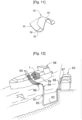
- the primary thermally insulating blocks 35 do not include anchoring strips 43. Indeed, to produce the primary waterproof membrane 6 around the through pipe 5, a closing plate 51, as illustrated on the figures 3 And 8 to 10 , placed on a thermal protection sheet 72, delimits a square of slightly larger size than the window 49 provided in the waterproof plates 48. An opening is cut in the center of the closing plate 51 to allow the passage of the through pipe 5. The closing plate 51 is welded in a watertight manner to the through pipe 5 via the flange 39.
- the waterproof plates 48 of the primary waterproof membrane 6 are welded to the anchoring strips 43 of the upper thermally insulating blocks 21a, 21b and the middle blocks 45.
- the welding of the waterproof plates 48 to the anchoring strips 43 makes it possible to retain the primary waterproof membrane 6 on the primary thermally insulating barrier 7.
- thermal protection strips 50 are arranged on the thermally insulating blocks primaries 35 to the right of the edges of the waterproof plates 48.
- the thermal protection sheet 72 and the thermal protection strips 50 are made of heat-resistant material, for example of composite material based on glass fibers. An opening is cut in the center of the thermal protection sheet 72 to allow the passage of the through pipe 5.
- the primary waterproof membrane 6 around the through pipe 5 is completed, on the one hand by welding the edges of the waterproof plates 48 delimiting the window 49 on the closing plate 51 and on the other hand by sealingly closing the ends of the corrugations 38a, 38b interrupted with end pieces 52.
- the diameter of the through pipe 5 is greater than the spacing between the undulations of the first series of undulations 38a, some of the transverse undulations whose direct line intersects the through pipe were interrupted at the window 49.
- the diameter of the through pipe 5 is greater than the spacing between the undulations of the second series of undulations 38b, some of the longitudinal undulations of which the guideline intersects the through pipe 5 were interrupted at the window 49 surrounding the through pipe 5.
- the end piece 52 comprises a sole in two parts 53, 54 intended to be welded in a sealed manner respectively on the closing plate 51 and on a waterproof plate 48, and a shell 55 intended to be welded tightly to the end of the corrugation.
- a recess 56 between the parts 53, 54 of the sole has an amplitude substantially equal to the thickness of the waterproof plate 48.
- the upper panel 37 of a primary thermally insulating block 35 has four grooves 57 passing right through the upper panel 37
- the closing plate 51 has grooves 69 superimposed on the grooves 57 of the primary thermally insulating blocks 35
- the sheet thermal protection 72 has grooves 70 superimposed on the grooves 57 of the primary thermally insulating blocks 35 and positioned under the grooves 69 of the closing plate 51.
- the insulating layer 36 also includes connecting grooves 74 positioned under the grooves 57 of the upper panel 37 from which three parallel grooves 75 extend respectively in the direction of the semi-circular cutout 76 of the primary thermally insulating block 35. In this way, the gas phase which has passed through the upper panel 37 can circulate to the outside of the primary thermally insulating block 35, in the space between the primary thermally insulating block 35 and the through pipe 5.
- This specific structure of the primary thermally insulating blocks 35 coupled to the spacing between the circular passage 32 and the through pipe 5, and to the internal space 30 comprising a porous lining makes it possible to create a circuit facilitating the circulation of the gas phase in the the primary sealed space, in particular from the undulations 38a, 38b to the secondary pipes 14, 15, and vice versa.
- the space between the opening 13 and the first peripheral connection plate 27 and between the supporting structure 3 and the secondary thermally insulating blocks 17 makes it possible to create a circuit facilitating the circulation of this gas phase between the secondary sealed space and the drum 12.
- the size of the window 49 is in practice larger than the diameter of the through pipe 5.
- the window 49 provided in the primary waterproof membrane 6 would be likely to similarly interrupt undulations including the guideline, without effectively cut the through pipe 5, would be in too close proximity to the through pipe 5.
- the center of the through pipe 5 is positioned between the direction lines of the interrupted transverse undulations 38a and between the direction lines of the interrupted longitudinal undulations 38b, and more precisely, as illustrated on the figures 9 And 10 , in the middle of these guidelines. It results from this positioning that the guide line each time cuts the through pipe 5 along a chord shorter than the diameter of the through pipe 5.
- this positioning of the through pipe 5 makes it possible to interrupt transverse undulations 38a or longitudinal undulations 38b over a shorter distance than in the case where the guideline would cut the through pipe 5 according to its largest transverse dimension or longitudinal, that is to say its diameter since the through pipe 5 here has a cylindrical shape of revolution with a circular section. It is advantageous to interrupt the undulations 38a, 38b of the primary waterproof membrane 6 over the shortest possible distance, given that these interruptions are likely to locally reduce the flexibility of the primary waterproof membrane 6 and therefore to locally promote its fatigue and its wear.
- a principle which can be used to adapt each time the positioning of the through pipe 5 between the undulations 38a, 38b is to choose a position which minimizes, or at least reduces, the dimension of the through pipe 5 which the guide line of the undulation 38a, 38b interrupted.
- a relevant optimization parameter for adapting the positioning of the through pipe 5 can be the length of the longest interruption or the cumulative length of the interruptions obtained.
- the through pipe 5 requires a window 49 of size approximately equal to twice the spacing between two undulations 38a, 38b, which are here equidistant. For this, two undulations 38a, 38b of each series were interrupted. However, this arrangement of the through pipe 5 and of the tank wall 2 in its vicinity can be adapted to other dimensions of the through pipe 5. For example, for a wider through pipe, the corresponding window 49 can interrupt a greater number of undulations 38a, 38b in one or each series, for example three or four or more undulations.
- the through pipe 5 passes through a ceiling wall of the sealed and thermally insulating tank 1
- the through pipe could pass through the tank wall 2 at the top of a side wall of the waterproof and thermally insulating tank 1 or at any other location in said waterproof and thermally insulating tank 1.
- the waterproof and thermally insulating tanks 1 described above can be used in different types of installations such as land-based installations or in a floating structure such as an LNG ship or other.
- a cutaway view of an LNG ship 58 shows a waterproof and thermally insulating tank 1 of generally prismatic shape mounted in the double hull 59 of the LNG ship 58.
- the tank wall 2 comprises a primary waterproof membrane 6 intended to be in contact with the LNG contained in the waterproof and thermally insulating tank 1, a secondary waterproof membrane 8 arranged between the primary waterproof membrane 6 and the double hull 59 of the LNG ship, and two thermally insulating barriers 7, 9 arranged respectively between the primary waterproof membrane 6 and the secondary waterproof membrane 8, and between the secondary waterproof membrane 8 and the double hull 59 of the LNG ship 58.
- loading/unloading pipes 60 arranged on the upper deck of the LNG ship 58 can be connected, by means of appropriate connectors, to a maritime or port terminal to transfer a cargo of liquefied gas, for example LNG , from or to the waterproof and thermally insulating tank 1.
- FIG. 12 also represents a maritime terminal comprising a loading and unloading station 61, an underwater pipeline 62 and a land installation 63.
- the loading and unloading station 61 is a fixed offshore installation comprising a movable arm 64 and a tower 65 which supports the movable arm 64.
- the movable arm 64 carries a bundle of insulated flexible pipes 66 which can connect to the loading pipes /unloading 60.
- the adjustable movable arm 64 adapts to all sizes of LNG ships 58.
- a connection pipe not shown extends inside the tower 65.
- the loading and unloading station 61 allows loading and the unloading of the LNG ship 58 from or to the onshore installation 63. This includes liquefied gas storage tanks 67 and connecting pipes 68 connected by the underwater pipe 62 to the loading and unloading station 61.
- the underwater pipe 62 allows the transfer of liquefied gas between the loading or unloading station 61 and the onshore installation 63 over a large distance, for example 5 km, which makes it possible to keep the LNG ship 58 at a long distance from the coast during loading and unloading operations.
- pumps are used on board the LNG ship 58 and/or pumps fitted to the on-shore installation 63 and/or pumps fitted to the loading and unloading station 61.
Abstract
L'invention concerne une cuve étanche et thermiquement isolante comportant une paroi de cuve une barrière thermiquement isolante secondaire 9, une membrane étanche secondaire 8, une barrière thermiquement isolante primaire 7 et une membrane étanche primaire 6. La cuve comporte également une conduite traversante 5 disposée à travers la paroi de cuve. Autour de la conduite traversante 5, la paroi de cuve comporte des blocs thermiquement isolants secondaires 17 formant la barrière thermiquement isolante secondaire 9, une première nappe étanche 20 formant la membrane étanche secondaire 8, des blocs thermiquement isolants primaires 35 formant la barrière thermiquement isolante primaire 6, et une plaque de fermeture liée de manière étanche à la membrane étanche primaire 6.The invention relates to a waterproof and thermally insulating tank comprising a tank wall, a secondary thermally insulating barrier 9, a secondary waterproof membrane 8, a primary thermally insulating barrier 7 and a primary waterproof membrane 6. The tank also includes a through pipe 5 arranged through the tank wall. Around the through pipe 5, the tank wall comprises secondary thermally insulating blocks 17 forming the secondary thermally insulating barrier 9, a first waterproof sheet 20 forming the secondary waterproof membrane 8, primary thermally insulating blocks 35 forming the primary thermally insulating barrier 6, and a closing plate sealed in a sealed manner to the primary waterproof membrane 6.
Description
L'invention se rapporte au domaine de la fabrication de cuves étanches et thermiquement isolantes. En particulier, la présente invention se rapporte à des cuves destinées à contenir des liquides froids ou chauds, et plus particulièrement des cuves pour le stockage et/ou le transport de gaz liquéfié par voie maritime disposées dans une structure porteuse.The invention relates to the field of manufacturing waterproof and thermally insulating tanks. In particular, the present invention relates to tanks intended to contain cold or hot liquids, and more particularly tanks for the storage and/or transport of liquefied gas by sea arranged in a supporting structure.
Des cuves étanches et thermiquement isolantes peuvent être utilisées dans différentes industries pour stocker un produit chaud ou froid. Par exemple, dans le domaine de l'énergie, un tel produit peut être du gaz naturel liquéfié (GNL). Le GNL est un liquide qui peut être stocké à pression atmosphérique à environ -163°C dans des cuves de stockages terrestres ou dans des cuves embarquées dans des structures flottantes. De telles structures flottantes sont en particulier les barges, les navires méthaniers pour le transport du produit et les installations off-shore, connues notamment sous les acronymes FPSO et FSRU, pour le stockage, la liquéfaction ou la regazéification du produit.Airtight and thermally insulating tanks can be used in different industries to store a hot or cold product. For example, in the energy field, such a product may be liquefied natural gas (LNG). LNG is a liquid that can be stored at atmospheric pressure at around -163°C in land-based storage tanks or in tanks on board floating structures. Such floating structures are in particular barges, LNG ships for transporting the product and off-shore installations, known in particular by the acronyms FPSO and FSRU, for the storage, liquefaction or regasification of the product.
Ces cuves étanches et thermiquement isolantes sont constituées d'une ou plusieurs membranes étanches associées à des couches isolantes. On connaît, notamment décrit dans
Les membranes étanches présentent une élasticité suffisante pour résister à des efforts résultant par exemple de la pression hydrostatique, de la pression dynamique en cas de mouvement de la cargaison, et/ ou des variations de température. Toutefois, de telles membranes étanches et le matériau d'isolation thermique sous-jacent sont relativement fragiles et ne peuvent pas nécessairement supporter le poids d'un mat comme celui de chargement/déchargement des cuves GNL. Pour cela un pied de support peut être prévu comme dans
De plus, les conditions thermodynamiques des cuves étanches et thermiquement isolantes lors du stockage d'un tel liquide entrainent une évaporation d'une certaine quantité de vapeur qui fait varier la pression interne des cuves. Pour contrôler la pression de ces cuves, les gaz d'évaporation sont collectés et acheminés vers un collecteur d'évaporation pour être par exemple reliquéfiés ou brûlés dans la machine de propulsion d'un navire. Pour cela une conduite collectrice peut être prévu comme dans
Il existe donc différentes fonctionnalités qui peuvent nécessiter de traverser la structure multicouche de la paroi de cuve avec une conduite traversante.There are therefore different functionalities which may require crossing the multi-layer structure of the tank wall with a through pipe.
Dans les cuves du type précité, il se produit des déformations de tous les éléments en raison des changements de température affectant la paroi de cuve lors de son remplissage avec un liquide très froid comme du GNL, et a contrario, lors de sa vidange entrainant un retour à température ambiante. En sus de ces effets thermiques de contraction et de dilatation, qui se répètent dans le temps au cours de la vie de la cuve étanche et thermiquement isolante, les cuves de navires subissent aussi des efforts dus à la déformation de la coque du navire à la mer. Il en résulte des phénomènes de fatigue des éléments, qu'il y a lieu de surveiller au cours du temps pour prévenir toute rupture.In tanks of the aforementioned type, deformations occur in all the elements due to temperature changes affecting the tank wall during its filling with a very cold liquid such as LNG, and conversely, during its emptying resulting in a return to room temperature. In addition to these thermal effects of contraction and expansion, which are repeated over time during the life of the watertight and thermally insulating tank, ship tanks also undergo forces due to the deformation of the ship's hull at the Wed. This results in fatigue phenomena of the elements, which must be monitored over time to prevent any breakage.
Une idée à la base de l'invention est de renforcer la résistance à la fatigue de la paroi de cuve dans la zone autour de laquelle la conduite traversante traverse la structure multicouche.An idea underlying the invention is to reinforce the fatigue resistance of the tank wall in the area around which the through pipe passes through the multilayer structure.
Selon un mode de réalisation, l'invention fournit une cuve étanche et thermiquement isolante agencée dans une structure porteuse pour contenir un fluide, la cuve étanche et thermiquement isolante comportant
- une paroi de cuve ancrée contre la structure porteuse, la paroi de cuve présentant une structure multicouche qui comporte successivement, dans une direction d'épaisseur depuis l'extérieur vers l'intérieur de ladite cuve étanche et thermiquement isolante, une barrière thermiquement isolante secondaire, une membrane étanche secondaire portée par la barrière thermiquement isolante secondaire, une barrière thermiquement isolante primaire portée par la membrane étanche secondaire et une membrane étanche primaire portée par la barrière thermiquement isolante primaire et qui est destinée à être en contact avec le fluide contenu dans ladite cuve étanche et thermiquement isolante, la structure multicouche comportant un espace primaire disposé entre la membrane étanche primaire et la membrane étanche secondaire, l'espace primaire contenant la barrière thermiquement isolante primaire, et
- une conduite traversante disposée à travers la paroi de cuve, la membrane étanche primaire étant liée de manière étanche à la conduite traversante,
- ladite paroi de cuve comportant autour de la conduite traversante
- des blocs thermiquement isolants secondaires ancrés contre la structure porteuse, les blocs thermiquement isolants secondaires formant la barrière thermiquement isolante secondaire autour de la conduite traversante, chacun desdits blocs thermiquement isolants secondaires présentant au moins un côté latéral se développant selon la direction d'épaisseur de la paroi de cuve, lesdits blocs thermiquement isolants secondaires étant agencés entre eux de sorte à ménager une cheminée entre les côtés latéraux en regard l'un de l'autre de deux blocs thermiquement isolants secondaires adjacents,
- une nappe étanche recouvrant les blocs thermiquement isolants secondaires, la nappe étanche formant la membrane étanche secondaire,
- un plateau étanche disposé parallèlement à la paroi de cuve, le plateau étanche présentant une surface intérieure tournée vers l'intérieur de ladite cuve étanche et thermiquement isolante, la surface intérieure étant située au même niveau que la nappe étanche, le plateau étanche étant disposé autour de la conduite traversante, la membrane étanche secondaire étant prolongée jusqu'au plateau étanche,
- une conduite extérieure s'étendant parallèlement à la conduite traversante autour de la conduite traversante vers l'extérieur de ladite cuve étanche et thermiquement isolante depuis le plateau étanche, la conduite extérieure étant en communication avec l'espace primaire pour permettre la circulation d'un gaz d'inertage entre l'espace primaire et la conduite extérieure,
- des blocs thermiquement isolants primaires disposés sur la membrane étanche secondaire, les blocs thermiquement isolants primaires formant la barrière thermiquement isolante primaire autour de la conduite traversante, un premier et un deuxième desdits blocs thermiquement isolants primaires présentant un côté latéral se développant selon la direction d'épaisseur de la paroi de cuve, le côté latéral présentant une portion découpée pour recevoir une portion de la conduite traversante et au moins une portion d'interface adjacente à la portion découpée, la portion d'interface dudit premier bloc thermiquement isolant primaire étant agencée en regard de la portion d'interface dudit deuxième bloc thermiquement isolant primaire,
- lesdits blocs thermiquement isolants secondaires et lesdits premier et deuxième blocs thermiquement isolants primaires étant disposés entre eux de sorte que la portion d'interface dudit premier bloc thermiquement isolant primaire et la portion d'interface dudit deuxième bloc thermiquement isolant primaire ne présentent aucun recouvrement, dans la direction de l'épaisseur, avec la cheminée entre deux blocs thermiquement isolants secondaires adjacents.
- a tank wall anchored against the supporting structure, the tank wall having a multilayer structure which successively comprises, in a thickness direction from the outside towards the inside of said sealed and thermally insulating tank, a secondary thermally insulating barrier, a secondary waterproof membrane carried by the secondary thermally insulating barrier, a primary thermally insulating barrier carried by the secondary waterproof membrane and a primary waterproof membrane carried by the primary thermally insulating barrier and which is intended to be in contact with the fluid contained in said tank waterproof and thermally insulating, the multilayer structure comprising a primary space disposed between the primary waterproof membrane and the secondary waterproof membrane, the primary space containing the primary thermally insulating barrier, and
- a through pipe arranged through the tank wall, the primary waterproof membrane being sealed in a sealed manner to the through pipe,
- said tank wall comprising around the through pipe
- secondary thermally insulating blocks anchored against the supporting structure, the secondary thermally insulating blocks forming the secondary thermally insulating barrier around the through pipe, each of said secondary thermally insulating blocks having at least one lateral side developing in the direction of thickness of the tank wall, said secondary thermally insulating blocks being arranged together so as to provide a chimney between the lateral sides facing each other of two adjacent secondary thermally insulating blocks,
- a waterproof layer covering the secondary thermally insulating blocks, the waterproof layer forming the secondary waterproof membrane,
- a sealed plate arranged parallel to the tank wall, the sealed plate having an interior surface facing the inside of said sealed and thermally insulating tank, the interior surface being located at the same level as the waterproof layer, the waterproof plate being arranged around of the through pipe, the secondary waterproof membrane being extended to the waterproof plate,
- an external pipe extending parallel to the through pipe around the through pipe towards the outside of said sealed and thermally insulating tank from the sealed plate, the external pipe being in communication with the primary space to allow the circulation of a inerting gas between the primary space and the external pipe,
- primary thermally insulating blocks arranged on the secondary waterproof membrane, the primary thermally insulating blocks forming the primary thermally insulating barrier around the through pipe, a first and a second of said primary thermally insulating blocks having a lateral side developing in the direction of thickness of the tank wall, the lateral side having a cut-out portion to receive a portion of the through pipe and at least one interface portion adjacent to the cut-out portion, the interface portion of said first primary thermally insulating block being arranged in view of the interface portion of said second primary thermally insulating block,
- said secondary thermally insulating blocks and said first and second primary thermally insulating blocks being arranged between them so that the interface portion of said first primary thermally insulating block and the interface portion of said second primary thermally insulating block have no overlap, in the thickness direction, with the chimney between two adjacent secondary thermally insulating blocks.
Grâce à ces caractéristiques, il est possible d'augmenter la résistance à la fatigue de la membrane étanche secondaire, tout en conservant une membrane d'étanchéité en nappe souple à cheval entre les blocs thermiquement isolants secondaires. En effet,
l'absence de recouvrement, dans la direction d'épaisseur, entre les portions d'interface de deux blocs thermiquement isolants primaires adjacents et les cheminées des blocs thermiquement isolants secondaires adjacents évite le risque d'une sollicitation accrue de la membrane étanche secondaire due aux contractions thermiques ou aux efforts de pression.Thanks to these characteristics, it is possible to increase the fatigue resistance of the secondary waterproof membrane, while retaining a flexible sheet waterproofing membrane straddling the secondary thermally insulating blocks. Indeed,
the absence of overlap, in the thickness direction, between the interface portions of two adjacent primary thermally insulating blocks and the chimneys of the adjacent secondary thermally insulating blocks avoids the risk of increased stress on the secondary waterproof membrane due to thermal contractions or pressure forces.
Selon des modes de réalisation, une telle cuve étanche et thermiquement isolante peut comporter une ou plusieurs des caractéristiques suivantes.According to embodiments, such a waterproof and thermally insulating tank may include one or more of the following characteristics.
Selon un mode de réalisation, la nappe étanche est une première nappe étanche recouvrant les blocs thermiquement isolants secondaires et dans laquelle ladite paroi de cuve comporte une deuxième nappe étanche fixée de manière étanche à cheval sur la première nappe étanche et sur la surface intérieure du plateau étanche autour de la conduite traversante, la deuxième nappe étanche prolongeant la membrane étanche secondaire jusqu'au plateau étanche.According to one embodiment, the waterproof layer is a first waterproof layer covering the secondary thermally insulating blocks and in which said tank wall comprises a second waterproof layer fixed in a sealed manner astride the first waterproof layer and on the interior surface of the plate waterproof around the through pipe, the second waterproof layer extending the secondary waterproof membrane to the waterproof plate.
Selon un mode de réalisation, la deuxième nappe étanche comporte au moins deux bandes étanches, chaque bande étanche étant disposée à cheval entre deux blocs thermiquement isolants secondaires adjacents.According to one embodiment, the second waterproof sheet comprises at least two waterproof strips, each waterproof strip being arranged astride two adjacent secondary thermally insulating blocks.
Selon un mode de réalisation, la deuxième nappe étanche comporte deux bandes étanches situées dans le prolongement l'une de l'autre, de part et d'autre de la conduite traversante de sorte à recouvrir la cheminée.According to one embodiment, the second waterproof sheet comprises two waterproof strips located in the extension of one another, on either side of the through pipe so as to cover the chimney.
Selon un mode de réalisation, les deux bandes étanches de la deuxième nappe étanche sont positionnées perpendiculairement à ladite au moins portion d'interface du premier bloc thermiquement isolant primaire et ladite au moins une portion d'interface du deuxième bloc thermiquement isolant primaire.According to one embodiment, the two waterproof strips of the second waterproof layer are positioned perpendicular to said at least interface portion of the first primary thermally insulating block and said at least one interface portion of the second primary thermally insulating block.
Selon un mode de réalisation, la paroi de cuve comporte deux panneaux préfabriqués disposés de part et d'autre de la conduite traversante, chacun des panneaux préfabriqués comportant un bloc thermiquement isolant inférieur constituant un dit bloc thermiquement secondaire, la première nappe étanche recouvrant le bloc thermiquement isolant secondaire, et un bloc thermiquement isolant supérieur disposé sur une zone centrale de la première nappe étanche et du bloc thermiquement isolant inférieur sans recouvrir une zone périphérique de la première nappe étanche, le bloc thermiquement isolant supérieur faisant partie de la barrière thermiquement isolante primaire, lesdits blocs thermiquement isolants primaires étant agencés entre les blocs thermiquement isolants supérieurs des deux panneaux préfabriqués sur ladite zone périphérique de la première nappe étanche des deux panneaux préfabriqués et sur ladite cheminée.According to one embodiment, the tank wall comprises two prefabricated panels arranged on either side of the through pipe, each of the prefabricated panels comprising a lower thermally insulating block constituting a said thermally secondary block, the first waterproof layer covering the block secondary thermally insulating layer, and an upper thermally insulating block arranged on a central zone of the first waterproof layer and the thermally insulating block lower without covering a peripheral zone of the first waterproof layer, the upper thermally insulating block forming part of the primary thermally insulating barrier, said primary thermally insulating blocks being arranged between the upper thermally insulating blocks of the two prefabricated panels on said peripheral zone of the first waterproof layer of the two prefabricated panels and on said chimney.
Selon un mode de réalisation, la membrane étanche primaire comporte des plaques étanches reliées entre elles de manière étanche au niveau de bords des plaques étanches, et les blocs thermiquement isolants supérieurs des deux panneaux préfabriqués portent des bandes d'ancrage au droit desdits bords des plaques étanches pour ancrer les plaques étanches auxdits panneaux préfabriqués, les blocs thermiquement isolants primaires comportant des bandes de protection thermique au droit desdits bords des plaques étanches de sorte que les plaques étanches ne sont pas ancrées auxdits blocs thermiquement isolants primaires.According to one embodiment, the primary waterproof membrane comprises waterproof plates connected together in a watertight manner at the edges of the waterproof plates, and the upper thermally insulating blocks of the two prefabricated panels carry anchoring strips to the right of said edges of the plates. waterproof to anchor the waterproof plates to said prefabricated panels, the primary thermally insulating blocks comprising thermal protection strips at the right of said edges of the waterproof plates so that the waterproof plates are not anchored to said primary thermally insulating blocks.
Selon un mode de réalisation, la membrane étanche primaire comporte au moins une série d'ondulations comportant des ondulations s'étendant selon des lignes directrices parallèles les unes aux autres, lesdites ondulations faisant saillie vers l'intérieur de ladite cuve étanche et thermiquement isolante, et dans laquelle une fenêtre interrompt au moins une ligne directrice d'une ondulation de ladite série d'ondulations,
ladite ondulation présentant de préférence une extrémité ouverte au niveau de la fenêtre, ladite cuve étanche et thermiquement isolante comportant au moins une pièce de bout pour fermer l'extrémité ouverte de ladite au moins une ondulation.According to one embodiment, the primary waterproof membrane comprises at least one series of corrugations comprising corrugations extending along direction lines parallel to each other, said corrugations projecting towards the interior of said waterproof and thermally insulating tank, and in which a window interrupts at least one direction line of an undulation of said series of undulations,
said corrugation preferably having an open end at the window, said sealed and thermally insulating tank comprising at least one end piece to close the open end of said at least one corrugation.
Selon un mode de réalisation, la fenêtre interrompt au moins deux lignes directrices d'ondulations de ladite au moins une série d'ondulations, et la conduite traversante est centrée à une position située entre deux desdites lignes directrices d'ondulations interrompues.According to one embodiment, the window interrupts at least two undulation guidelines of said at least one series of undulations, and the through pipe is centered at a position located between two of said interrupted undulation guidelines.
Les dispositions et caractéristiques énoncées ci-dessus vis-à-vis d'une série d'ondulations parallèles peuvent, le cas échéant, être appliquées vis-à-vis de plusieurs séries d'ondulations parallèles ayant des directions différentes.The arrangements and characteristics set out above with respect to a series of parallel undulations can, where appropriate, be applied to several series of parallel undulations having different directions.
Selon un mode de réalisation, la membrane étanche primaire comporte une première série d'ondulations et une deuxième série d'ondulations sécante à la première série d'ondulations, la fenêtre interrompt au moins deux lignes directrices des ondulations de la première série d'ondulations et au moins deux lignes directrices des ondulations de la deuxième série d'ondulations, et la conduite traversante est centrée à une position située entre deux lignes directrices des ondulations interrompues de ladite première série d'ondulations et deux lignes directrices des ondulations interrompues de ladite deuxième série d'ondulations.According to one embodiment, the primary waterproof membrane comprises a first series of undulations and a second series of undulations secant to the first series of undulations, the window interrupts at least two direction lines of the undulations of the first series of undulations and at least two direction lines of the undulations of the second series of undulations, and the through pipe is centered at a position located between two direction lines of the interrupted undulations of said first series of undulations and two direction lines of the interrupted undulations of said second series of undulations.
Selon un mode de réalisation, les lignes directrices des ondulations de la première série d'ondulations sont perpendiculaires aux lignes directrices des ondulations de la deuxième série d'ondulations.According to one embodiment, the direction lines of the undulations of the first series of undulations are perpendicular to the direction lines of the undulations of the second series of undulations.
La fenêtre précitée peut présenter différentes formes, notamment en fonction de la forme de la conduite traversante et/ou de la forme des éléments constitutifs de la membrane étanche primaire.The aforementioned window can have different shapes, in particular depending on the shape of the through pipe and/or the shape of the constituent elements of the primary waterproof membrane.
Selon un mode de réalisation, la fenêtre est un quadrilatère comportant deux côtés parallèles aux lignes directrices des ondulations de la première série d'ondulations et deux côtés parallèles aux lignes directrices des ondulations de la deuxième série d'ondulations. En particulier, la fenêtre peut être un carré, un rectangle ou un parallélogramme.According to one embodiment, the window is a quadrilateral having two sides parallel to the direction lines of the undulations of the first series of undulations and two sides parallel to the direction lines of the undulations of the second series of undulations. In particular, the window can be a square, a rectangle or a parallelogram.
Selon un mode de réalisation, la conduite traversante présente une section circulaire et traverse la fenêtre en son centre.According to one embodiment, the through pipe has a circular section and crosses the window in its center.
Selon un mode de réalisation, la conduite extérieure comporte une première plaque de liaison périphérique et une deuxième plaque de liaison périphérique, la deuxième plaque de liaison périphérique étant fixée de manière étanche à la première plaque de liaison périphérique tout autour de ladite première plaque de liaison périphérique, la première plaque de liaison périphérique s'étendant parallèlement à la conduite traversante vers l'extérieur de ladite cuve étanche et thermiquement isolante depuis la deuxième plaque de liaison périphérique, ladite deuxième plaque de liaison périphérique étant fixée de manière étanche au plateau étanche et faisant saillie vers la structure porteuse parallèlement à la conduite traversante.According to one embodiment, the external pipe comprises a first peripheral connection plate and a second peripheral connection plate, the second peripheral connection plate being fixed in a sealed manner to the first peripheral connection plate all around said first connection plate peripheral, the first peripheral connecting plate extending parallel to the through pipe towards the outside of said sealed and thermally insulating tank from the second peripheral connecting plate, said second peripheral connecting plate being fixed in a sealed manner to the sealed plate and projecting towards the supporting structure parallel to the through pipe.
Selon un mode de réalisation, la paroi de cuve comporte en outre, autour de la conduite traversante, au moins une plaque de fermeture disposée sur les blocs thermiquement isolants primaires et liée de manière étanche à la conduite traversante.According to one embodiment, the tank wall further comprises, around the through pipe, at least one closure plate arranged on the primary thermally insulating blocks and sealed in a sealed manner to the through pipe.
Selon un mode de réalisation, la plaque de fermeture est constituée d'une plaque métallique d'un seul tenant entourant la conduite traversante.According to one embodiment, the closure plate consists of a single piece metal plate surrounding the through pipe.
Selon un mode de réalisation, au moins l'un desdits blocs thermiquement isolants primaires comporte au moins une rainure, et la plaque de fermeture comporte au moins une rainure recouverte par l'une dite pièce de bout et superposée à ladite rainure du bloc thermiquement isolant primaire de manière à permettre la circulation d'un gaz d'inertage entre l'ondulation et la conduite extérieure.According to one embodiment, at least one of said primary thermally insulating blocks comprises at least one groove, and the closing plate comprises at least one groove covered by one of said end pieces and superimposed on said groove of the thermally insulating block primary so as to allow the circulation of an inerting gas between the corrugation and the external pipe.
Selon un mode de réalisation, la paroi de cuve comporte une feuille de protection thermique intercalée entre les blocs thermiquement isolants primaires et la plaque de fermeture.According to one embodiment, the tank wall comprises a thermal protection sheet interposed between the primary thermally insulating blocks and the closure plate.
Avantageusement, la feuille de protection thermiquement est filmée d'un seul tenant autour de la conduite traversante.Advantageously, the thermally protective sheet is filmed in one piece around the through pipe.
Avantageusement, la feuille de protection thermique comporte au moins une rainure superposée à l'une dite rainure du bloc thermiquement isolant primaire et positionnée sous l'une dite rainure de la plaque de fermeture.Advantageously, the thermal protection sheet comprises at least one groove superimposed on one said groove of the primary thermally insulating block and positioned under one said groove of the closing plate.
Selon un mode de réalisation, la conduite traversante définit un passage entre l'intérieur de la cuve étanche et thermiquement isolante et un collecteur de vapeur agencé à l'extérieur de ladite cuve étanche et thermiquement isolante.According to one embodiment, the through pipe defines a passage between the interior of the sealed and thermally insulating tank and a steam collector arranged outside of said sealed and thermally insulating tank.
Une telle cuve peut faire partie d'une installation de stockage terrestre, par exemple pour stocker du gaz liquéfié ou être installée dans une structure flottante, côtière ou en eau profonde, notamment un navire méthanier, un navire de transport de GPL, une unité flottante de stockage et de regazéification (FSRU), une unité flottante de production et de stockage déporté (FPSO) et autres.Such a tank can be part of a land storage installation, for example to store liquefied gas or be installed in a floating, coastal or deep water structure, in particular an LNG ship, an LPG transport ship, a floating unit storage and regasification unit (FSRU), a floating production and remote storage unit (FPSO) and others.
Selon un mode de réalisation, l'invention fournit aussi un navire pour le transport d'un produit liquide froid, le navire comportant une double coque et une cuve étanche et thermiquement isolante disposée dans la double coque.According to one embodiment, the invention also provides a ship for transporting a cold liquid product, the ship comprising a double hull and a waterproof and thermally insulating tank placed in the double hull.
Selon un mode de réalisation, l'invention fournit également l'utilisation d'un navire pour le chargement ou le déchargement d'un produit liquide froid, dans laquelle on achemine un produit liquide froid à travers des canalisations isolées depuis ou vers une installation de stockage flottante ou terrestre vers ou depuis la cuve étanche et thermiquement isolante du navire.According to one embodiment, the invention also provides the use of a vessel for loading or unloading a cold liquid product, in which a cold liquid product is conveyed through insulated pipes from or to a processing installation. floating or land storage to or from the ship's watertight and thermally insulating tank.
Selon un mode de réalisation, l'invention fournit également un système de transfert pour un liquide froid, le système comportant un navire, des canalisations isolées agencées de manière à relier la cuve étanche et thermiquement isolante installée dans la coque du navire à une installation de stockage flottante ou terrestre et une pompe pour entraîner un flux de produit liquide froid à travers les canalisations isolées depuis ou vers l'installation de stockage flottante ou terrestre vers ou depuis la cuve étanche et thermiquement isolante du navire.According to one embodiment, the invention also provides a transfer system for a cold liquid, the system comprising a ship, insulated pipes arranged so as to connect the waterproof and thermally insulating tank installed in the hull of the ship to an installation of floating or land-based storage facility and a pump for driving a flow of cold liquid product through the insulated pipelines to or from the floating or land-based storage facility to or from the vessel's sealed and thermally insulated tank.
L'invention sera mieux comprise, et d'autres buts, détails, caractéristiques et avantages de celle-ci apparaîtront plus clairement au cours de la description suivante de plusieurs modes de réalisation particuliers de l'invention, donnés uniquement à titre illustratif et non limitatif, en référence aux dessins annexés.
- [
Fig. 1 ] Lafigure 1 est une vue en coupe d'une paroi de cuve selon un mode de réalisation de l'invention comportant un dispositif de collecte de fluides. - [
Fig. 2 ] Lafigure 2 est une vue en coupe agrandie de la zone II de lafigure 1 . - [
Fig. 3 ] Lafigure 3 est une vue partielle en perspective éclatée de la zone de paroi de cuve présentée à lafigure 2 . - [
Fig. 4 ] Lafigure 4 est une vue plane dans l'axe de la conduite traversante de la zone de la paroi de cuve présentée à lafigure 2 montrant la réalisation de la barrière thermiquement isolante secondaire, la barrière thermiquement isolante primaire étant omise, autour de la conduite traversante. - [
Fig. 5 ] Lafigure 5 est une vue analogue à lafigure 4 montrant la réalisation de la barrière thermiquement isolante primaire. - [
Fig. 6 ] Lafigure 6 est une vue en perspective éclatée d'un bloc thermiquement isolant primaire pouvant être utilisé dans la barrière thermiquement isolante primaire. - [
Fig. 7 ] Lafigure 7 est une vue analogue à lafigure 5 montrant le positionnement de la feuille de protection thermique et des bandes de protection thermique sur la barrière thermiquement isolante primaire. - [
Fig. 8 ] Lafigure 8 est une vue analogue à lafigure 7 à un stade intermédiaire de montage de la membrane étanche primaire. - [
Fig. 9 ] Lafigure 9 est une vue analogue à lafigure 8 mais à un stade plus avancé de montage de la membrane étanche primaire. - [
Fig. 10 ] Lafigure 10 est une vue analogue à lafigure 9 montrant la réalisation de la membrane étanche primaire. - [
Fig. 11 ] Lafigure 11 est une vue en perspective d'une pièce de bout pouvant être utilisée dans la fabrication de la membrane étanche primaire présentée à lafigure 10 . - [
Fig. 12 ] Lafigure 12 est une représentation schématique écorchée d'une cuve de navire méthanier et d'un terminal de chargement/déchargement de cette cuve.
- [
Fig. 1 ] Therefigure 1 is a sectional view of a tank wall according to one embodiment of the invention comprising a fluid collection device. - [
Fig. 2 ] Therefigure 2 is an enlarged sectional view of zone II of thefigure 1 . - [
Fig. 3 ] ThereFigure 3 is a partial exploded perspective view of the tank wall area presented in thefigure 2 . - [
Fig. 4 ] ThereFigure 4 is a planar view in the axis of the through pipe of the zone of the tank wall presented in thefigure 2 showing the creation of the secondary thermally insulating barrier, the primary thermally insulating barrier being omitted, around the through pipe. - [
Fig. 5 ] Therefigure 5 is a view analogous to thefigure 4 showing the creation of the primary thermally insulating barrier. - [
Fig. 6 ] ThereFigure 6 is an exploded perspective view of a primary thermally insulating block suitable for use in the primary thermally insulating barrier. - [
Fig. 7 ] ThereFigure 7 is a view analogous to thefigure 5 showing the positioning of the thermal protection sheet and thermal protection strips on the primary thermally insulating barrier. - [
Fig. 8 ] Therefigure 8 is a view analogous to theFigure 7 at an intermediate stage of assembly of the primary waterproof membrane. - [
Fig. 9 ] ThereFigure 9 is a view analogous to thefigure 8 but at a more advanced stage of assembly of the primary waterproof membrane. - [
Fig. 10 ] ThereFigure 10 is a view analogous to theFigure 9 showing the creation of the primary waterproof membrane. - [
Fig. 11 ] ThereFigure 11 is a perspective view of an end piece which can be used in the manufacture of the primary waterproof membrane presented in theFigure 10 . - [
Fig. 12 ] ThereFigure 12 is a cut-away schematic representation of an LNG ship tank and a loading/unloading terminal for this tank.
En référence à la
Par convention, les termes « sur », « au-dessus », « supérieur » et « haut » font généralement référence à une position située vers l'intérieur de la cuve étanche et thermiquement isolante 1 tandis que les termes « sous », « en-dessous », « inférieur » et « bas » font généralement référence à une position située vers l'extérieur de la cuve étanche et thermiquement isolante 1, quelle que soit l'orientation de la paroi de cuve 2 par rapport au champ de gravité terrestre.By convention, the terms "on", "above", "superior" and "top" generally refer to a position located towards the inside of the waterproof and thermally insulating
La cuve étanche et thermiquement isolante 1 peut être réalisée selon différentes géométries, par exemple une géométrie prismatique dans la coque d'un navire ou une géométrie cylindrique à terre ou autre.The waterproof and thermally insulating
Les modes de réalisation ci-après sont décrits en relation avec une cuve étanche et thermiquement isolante 1 destinée pour le stockage et/ou le transport de gaz naturel liquéfié par voie maritime. Dans des variantes non décrites, une telle cuve étanche et thermiquement isolante 1 peut être une cuve utilisée pour le stockage terrestre d'autres produits froids ou chauds.The embodiments below are described in relation to a waterproof and thermally insulating
Les
En référence à la
Le dispositif de collecte de fluides 4 comporte un fût 12 qui s'étend à l'extérieur de la structure porteuse 3, ainsi que la conduite traversante 5, ancrée à l'intérieur du fût 12. Le fût 12 et la conduite traversante 5 présentent ici une forme cylindrique de révolution à section circulaire. Toutefois, d'autres formes peuvent être envisagées. La structure porteuse 3 comporte une ouverture circulaire 13. Le fût 12 est soudé autour de l'ouverture circulaire 13. La conduite traversante 5 traverse la paroi de cuve 2 au centre de l'ouverture circulaire 13. Ainsi, la conduite traversante 5 traverse les membranes étanches primaire 6 et secondaire 8, et les barrières thermiquement isolantes primaire 7 et secondaire 9, pour déboucher à l'intérieur de la cuve étanche et thermiquement isolante 1. La conduite traversante 5 est notamment reliée à un collecteur de vapeur à l'extérieur de la cuve étanche et thermiquement isolante qui extrait cette vapeur et la transmet par exemple au dispositif de propulsion du navire pour alimenter la propulsion du navire ou à un dispositif de liquéfaction pour réintroduire ensuite le gaz liquéfié dans la cuve.The
La membrane étanche primaire 6 est reliée de manière étanche à la conduite traversante 5. La membrane étanche secondaire 8 est également reliée de manière étanche à la conduite traversante 5 sauf en un passage permettant à une phase gazeuse présente entre la membrane étanche primaire 6 et la membrane étanche secondaire 8 de circuler vers deux conduites secondaires 14, 15. La phase gazeuse est typiquement du diazote ou un autre gaz d'inertage. De cette manière, l'espace entre la membrane étanche primaire 6 et la membrane étanche secondaire 8 forme un espace étanche primaire relié aux deux conduites secondaires 14, 15.The primary
Par ailleurs, le fût 12 est relié de manière étanche à la structure porteuse 3. Une couche d'isolation 16 est répartie uniformément sur la portée extérieure de la conduite traversante 5 qui présente un diamètre inférieur à l'ouverture circulaire 13. De cette manière, l'espacement entre la couche d'isolation 16 et l'ouverture circulaire 13 permet la circulation d'une phase gazeuse entre la barrière thermiquement isolante secondaire 9 et un espace intermédiaire présent entre le fût 12 et la couche d'isolation 16. La phase gazeuse est typiquement du diazote ou un autre gaz d'inertage. L'espace intermédiaire et l'espace entre la structure porteuse 3 et la barrière thermiquement isolante secondaire 9 forment ainsi un espace étanche secondaire.Furthermore, the
Les deux conduites secondaires 14, 15 s'étendent parallèlement à la conduite traversante 5 dans la couche d'isolation 16, depuis l'extérieur du fût 12 jusqu'à l'espace étanche primaire. La première conduite secondaire 14 permet de réaliser un passage entre l'espace étanche primaire et un organe d'évacuation non représenté qui permet de contrôler la phase gazeuse présente dans l'espace primaire. La deuxième conduite secondaire 15 permet de réaliser un passage entre l'espace primaire et un organe de mesure de pression non représenté. Ces deux conduites secondaires 14, 15 permettent notamment de réaliser un balayage avec un gaz inerte, par exemple un balayage d'azote, dans l'espace étanche primaire.The two
Deux autres conduites non représentées sont soudées au fût 12 et débouchent à l'intérieur du fût 12 dans l'espace étanche secondaire pour permettre elles aussi la gestion de la phase gazeuse et la mesure de pression dans l'espace étanche secondaire. Les conduites reliées à l'espace étanche secondaire permettent aussi un balayage avec un gaz inerte, par exemple un balayage d'azote, dans l'espace étanche secondaire.Two other pipes not shown are welded to the
En référence aux
Deux panneaux préfabriqués 10a, 10b sont placés à proximité de la conduite traversante 5. En référence à la
Une première nappe étanche 20 en matériau composite comportant par exemple une feuille métallique et des nappes de fibres de verre noyées dans une résine adhère sur toute la surface de la couche d'isolant thermique 19 du bloc thermiquement isolant secondaire 17. La première nappe étanche 20 constitue un élément de la membrane étanche secondaire 8.A first
Le panneau préfabriqué 10a, 10b comporte également un bloc thermiquement isolant supérieur 21a, 21b. Le bloc thermiquement isolant supérieur 21a, 21b comporte une couche d'isolant thermique 22 en mousse polyuréthane qui recouvre partiellement la première nappe étanche 20 et y adhère. Un panneau supérieur 23 rigide recouvre la couche d'isolant thermique 22 et constitue avec elle un élément de la barrière thermiquement isolante primaire 7.The
Comme expliqué ci-dessus en référence à la
L'étanchéité entre la barrière thermiquement isolante secondaire 9 et la conduite traversante 5 est réalisée par l'intermédiaire du plateau d'obturation 24, d'une première plaque de liaison périphérique 27, d'une deuxième plaque de liaison périphérique 28 et d'un plateau étanche 29. La première plaque de liaison périphérique 27, de forme tubulaire, est fixée de manière étanche sur toute sa périphérie sur le plateau d'obturation 24 et s'étend parallèlement à la conduite traversante 5 vers l'intérieur de la cuve étanche et thermiquement isolante 1 pour former une conduite extérieure. À son extrémité, opposée au plateau d'obturation 24, elle est reliée par l'intermédiaire de la deuxième plaque de liaison périphérique 28, également de forme tubulaire, au plateau étanche 29 de forme circulaire. De cette manière, le plateau d'obturation 24, le plateau étanche 29 et les plaques de liaisons périphériques 27, 28 forment un espace interne 30 de la conduite extérieure, adossé à la paroi extérieure de la conduite traversante 5. Une deuxième nappe étanche 31 est fixée de manière étanche à cheval sur la première nappe étanche 20 et sur le plateau étanche 29 pour réaliser l'étanchéité de la membrane étanche secondaire 8.The seal between the secondary thermally insulating
Le plateau étanche 29 comporte un passage circulaire 32 traversé par la conduite traversante 5. Ce passage circulaire 32 présente un diamètre supérieur au diamètre de la conduite traversante 5 de manière à laisser un espacement entre le plateau étanche 29 et la conduite traversante 5. Grâce à cet espacement, la phase gazeuse peut circuler depuis l'espace étanche primaire situé entre la membre étanche primaire 6 et la membrane étanche secondaire 8 vers l'espace interne 30.The sealed
Pour permettre l'évacuation des vapeurs présentes dans l'espace interne 30, les deux conduites secondaires 14, 15 sont raccordées de manière étanche sur le plateau d'obturation 24. Cette architecture permet de réaliser le balayage avec un gaz inerte. Pour garantir l'isolation, l'espace interne 30 est rempli d'un isolant perméable aux vapeurs ou gaz.To allow the evacuation of the vapors present in the
La deuxième plaque de liaison périphérique 28 de forme tubulaire est soudée sur la surface inférieure du plateau étanche 29. La portée intérieure de la deuxième plaque de liaison périphérique 28 présente un diamètre sensiblement égal au diamètre externe de la première plaque de liaison périphérique 27. De cette manière, les plaques de liaison périphérique 27, 28 peuvent s'emboîter et coopérer pour coulisser lorsqu'elles ne sont pas soudées. Ainsi, lors du soudage de la deuxième plaque de liaison périphérique 28 avec la première plaque de liaison périphérique 27, l'écartement entre le plateau étanche 29 et la structure porteuse 3 peut être ajusté pour placer le plateau étanche 29 précisément au niveau de la membrane étanche secondaire 8. Par ailleurs, l'emboîtement de la première plaque de liaison périphérique 27 avec la deuxième plaque de liaison périphérique 28 permet le centrage de la conduite traversante 5 par rapport à l'ouverture 13, ainsi que l'orientation du plateau étanche 29. Les soudages entre le plateau d'obturation 24 et la première plaque de liaison périphérique 27, entre la première plaque de liaison périphérique 27 et la deuxième plaque de liaison périphérique 28, et entre la deuxième plaque de liaison périphérique 28 et le plateau étanche 29 sont réalisés de manière à obtenir l'étanchéité entre ces éléments.The second peripheral connecting
Le plateau d'obturation 24, le plateau étanche 29, la première plaque de liaison périphérique 27 et la deuxième plaque de liaison périphérique 28 sont des éléments métalliques, par exemple constituées d'acier inoxydable.The
En référence à la
En référence aux
En référence aux
Les blocs thermiquement isolants supérieurs 21a, 21b des panneaux préfabriqués 10a, 10b et les blocs thermiquement isolants primaires 35 supportent la membrane étanche primaire 6 réalisée sous forme de plaques métalliques présentant des ondulations 38a, 38 b. Ces ondulations 38a, 38b forment des zones élastiques pour absorber la contraction thermique et les efforts de pression statiques et dynamiques. De telles barrières d'étanchéité en tôle ondulée ou gaufrée ont notamment été décrites dans
La membrane étanche primaire 6 est reliée de manière étanche à la conduite traversante 5 par l'intermédiaire d'une collerette 39 de section formant un « L ». La collerette 39 est soudée sur la membrane étanche primaire 6 et sur la conduite traversante 5.The primary
En référence à la
La conduite traversante 5 et la première plaque de liaison périphérique 27 traversent la structure porteuse 3 au centre de l'ouverture 13. La première plaque de liaison périphérique 27 est centrée dans l'ouverture.The through
Une garniture en laine de verre est introduite dans l'espace interne 30. Ainsi que cela a été préalablement mentionné, cette garniture est poreuse pour permettre la libre circulation de la phase gazeuse dans l'espace interne 30 entre l'espace étanche primaire et les conduites secondaires 14, 15 (non représentées sur la
Le plateau étanche 29 est positionné de sorte à être précisément au même niveau que la membrane étanche secondaire 8 par soudure de la deuxième plaque de liaison périphérique 28 sur la première plaque de liaison périphérique 27. Pour éviter un risque de brûlure de la garniture en laine de verre, une protection thermique non représentée est préalablement placée entre la garniture et les plaques de liaison périphérique 27, 28.The
En référence aux
Plus précisément, chaque bloc thermiquement isolant secondaire 17 présente un côté 41 avec une découpe en forme de demi-cercle pour accueillir la première plaque de liaison périphérique 27 et la deuxième plaque de liaison périphérique 28. Le demi-cercle présente un diamètre supérieur au diamètre de la première plaque de liaison périphérique 27 et de la deuxième plaque de liaison périphérique 28, tel que cela est visible sur la
Les deux blocs thermiquement isolants secondaires 17 sont conçus pour ménager des espaces entre eux sous la forme de deux cheminées radiales inter-panneaux 42a, 42b. Pour assurer une continuité de la barrière thermiquement isolante secondaire 9, chacune des deux cheminées radiales inter-panneaux 42a, 42b est bourrée d'une garniture en laine de verre (non représentée) permettant la circulation de la phase gazeuse à travers la barrière thermiquement isolante secondaire 9, notamment pour l'inertage de la paroi de cuve avec un gaz inerte comme du diazote.The two secondary thermally insulating
Le panneau préfabriqué 10a, 10b peut être préfabriqué par collage avec de la mousse de polyuréthane et du bois contreplaqué pour les barrières thermiquement isolantes primaire 7 et secondaire 9. Ainsi le bloc thermiquement isolant secondaire 17 comporte le panneau inférieur 18 et la couche de mousse isolante 19 et le bloc thermiquement isolant supérieur 21a, 21b comporte la couche isolante 22 et le panneau supérieur 23. Le panneau supérieur 23 du bloc thermiquement isolant supérieur 21a, 21b comporte des lamages transversaux et longitudinaux dans lesquels sont logées des bandes d'ancrage 43 sur lesquelles est soudée la membrane étanche primaire 6, telle que ci-après décrit.The
Les deux panneaux préfabriqués 10a, 10b sont juxtaposés pour entourer la conduite traversante 5. Chaque panneau préfabriqué 10a, 10b comporte en outre des cheminées 44 qui permettent l'accès, lors du montage, aux goujons 71 préalablement soudés sur la structure porteuse permettant d'ancrer les panneaux préfabriqués 10a, 10b.The two
La deuxième nappe étanche 31 est collée à cheval sur la première nappe étanche 20 et sur le plateau étanche 29. La deuxième nappe étanche 31 comporte également deux bandes étanches radiales 31a, 31b disposées à cheval sur les deux blocs thermiquement isolants secondaires 17 au-dessus des cheminées 42a et 42b.The second
Deux blocs thermiquement isolant primaires 35 et deux blocs médians 45 sont positionnés par-dessus la deuxième nappe étanche 31 et la première nappe étanche 20 pour compléter la barrière thermiquement isolante primaire 7. Les blocs médians 45 sont installés sur les bandes étanches radiales 31a, 31b de la deuxième nappe étanche 31.Two primary thermally insulating
En référence à la
En référence à la
En référence aux
Les plaques étanches 48 de la membrane étanche primaire 6 comportent une pluralité d'ondulations 38a, 38b en saillie vers l'intérieur de la cuve étanchement et thermiquement isolante 1. Plus particulièrement, la membrane étanche primaire 6 comporte une première série d'ondulations 38a dites transversales et une deuxième série d'ondulations 38b dites longitudinales dont les directions respectives sont perpendiculaires. La deuxième série d'ondulations 38b présente une hauteur inférieure à la première série d'ondulations 38a.The
Sur la
Contrairement aux blocs thermiquement isolants supérieurs 21a, 21b des panneaux préfabriqués 10a, 10b, les blocs thermiquement isolant primaires 35 ne comportent pas de bandes d'ancrage 43. En effet, pour réaliser la membrane étanche primaire 6 autour de la conduite traversante 5, une plaque de fermeture 51, telle qu'illustrée sur les
En référence aux
La membrane étanche primaire 6 autour de la conduite traversante 5 est complétée, d'une part en soudant les bords des plaques étanches 48 délimitant la fenêtre 49 sur la plaque de fermeture 51 et d'autre part en fermant de manière étanche les extrémités des ondulations 38a, 38b interrompues avec des pièces de bout 52. En effet, comme le diamètre de la conduite traversante 5 est supérieur à l'espacement entre les ondulations de la première série d'ondulations 38a, certaines des ondulations transversales dont la ligne directrice coupe la conduite traversante ont été interrompues au niveau de la fenêtre 49. De même, comme le diamètre de la conduite traversante 5 est supérieur à l'espacement entre les ondulations de la deuxième série d'ondulations 38b, certaines des ondulations longitudinales dont la ligne directrice coupe la conduite traversante 5 ont été interrompues au niveau de la fenêtre 49 entourant la conduite traversante 5.The primary
En référence à la
En référence aux
Cette structure spécifique des blocs thermiquement isolants primaires 35 couplée à l'espacement entre le passage circulaire 32 et la conduite traversante 5, et à l'espace interne 30 comprenant une garniture poreuse permet de créer un circuit facilitant la circulation de la phase gazeuse dans l'espace étanche primaire, notamment depuis les ondulations 38a, 38b jusqu'aux conduites secondaires 14, 15, et inversement. De même que, ainsi que cela a été précédemment décrit, l'espace entre l'ouverture 13 et la première plaque de liaison périphérique 27 et entre la structure porteuse 3 et les blocs thermiquement isolants secondaires 17 permet de créer un circuit facilitant la circulation de cette phase gazeuse entre l'espace étanche secondaire et le fût 12. Ces circuits permettent notamment l'inertage de la paroi de cuve 2 avec un gaz inerte comme du diazote.This specific structure of the primary thermally insulating
En référence aux
Le centre de la conduite traversante 5 est positionné entre les lignes directrices des ondulations transversales 38a interrompues et entre les lignes directrices des ondulations longitudinales 38b interrompues, et plus précisément, tel qu'illustré sur les
Le centrage de la conduite traversante 5 à mi-distance entre les ondulations transversales 38a interrompues et les ondulations longitudinales 38b interrompues offre un résultat optimal. Toutefois, d'autres formes pour la conduite traversante 5 et d'autres centrages peuvent être envisagées. Un principe pouvant servir à adapter à chaque fois le positionnement de la conduite traversante 5 entre les ondulations 38a, 38b est de choisir une position qui minimise, ou du moins diminue, la dimension de la conduite traversante 5 que coupe la ligne directrice de l'ondulation 38a, 38b interrompue. Dans le cas où la géométrie particulière de la membrane étanche primaire 6 implique d'interrompre plusieurs ondulations 38a, 38b sur des longueurs différentes, un paramètre d'optimisation pertinent pour adapter le positionnement de la conduite traversante 5 peut être la longueur de la plus longue interruption ou la longueur cumulée des interruptions obtenues.Centering the through
La conduite traversante 5 nécessite une fenêtre 49 de taille approximativement égale à deux fois l'espacement entre deux ondulations 38a, 38b, lesquelles sont ici équidistantes. Pour cela, deux ondulations 38a, 38b de chaque série ont été interrompues. Toutefois, cet agencement de la conduite traversante 5 et de la paroi de cuve 2 à son voisinage peut être adapté à d'autres dimensions de la conduite traversante 5. Par exemple, pour une conduite traversante plus large, la fenêtre 49 correspondante peut interrompre un plus grand nombre d'ondulations 38a, 38b dans une ou chaque série, par exemple trois ou quatre ondulations ou plus.The through
Bien que dans le mode de réalisation décrit ci-dessus la conduite traversante 5 traverse une paroi de plafond de la cuve étanche et thermiquement isolante 1, dans un autre mode de réalisation, la conduite traversante pourrait traverser la paroi de cuve 2 en haut d'une paroi latérale de la cuve étanche et thermiquement isolante 1 ou encore à tout autre emplacement dans ladite cuve étanche et thermiquement isolante 1.Although in the embodiment described above the through
Les cuves étanches et thermiquement isolantes 1 décrites ci-dessus peuvent être utilisées dans différents types d'installations telles que des installations terrestres ou dans un ouvrage flottant comme un navire méthanier ou autre.The waterproof and thermally insulating
En référence à la
La paroi de cuve 2 comporte une membrane étanche primaire 6 destinée à être en contact avec le GNL contenu dans la cuve étanche et thermiquement isolante 1, une membrane étanche secondaire 8 agencée entre la membrane étanche primaire 6 et la double coque 59 du navire méthanier, et deux barrières thermiquement isolantes 7, 9 agencées respectivement entre la membrane étanche primaire 6 et la membrane étanche secondaire 8, et entre la membrane étanche secondaire 8 et la double coque 59 du navire méthanier 58.The
De manière connue en soi, des canalisations de chargement/déchargement 60 disposées sur le pont supérieur du navire méthanier 58 peuvent être raccordées, au moyen de connecteurs appropriés, à un terminal maritime ou portuaire pour transférer une cargaison de gaz liquéfié, par exemple du GNL, depuis ou vers la cuve étanche et thermiquement isolante 1.In a manner known per se, loading/unloading
La
Le poste de chargement et de déchargement 61 est une installation fixe off-shore comportant un bras mobile 64 et une tour 65 qui supporte le bras mobile 64. Le bras mobile 64 porte un faisceau de tuyaux flexibles isolés 66 pouvant se connecter aux canalisations de chargement/déchargement 60. Le bras mobile 64 orientable s'adapte à tous les gabarits de navires méthaniers 58. Une conduite de liaison non représentée s'étend à l'intérieur de la tour 65. Le poste de chargement et de déchargement 61 permet le chargement et le déchargement du navire méthanier 58 depuis ou vers l'installation à terre 63. Celle-ci comporte des cuves de stockage de gaz liquéfié 67 et des conduites de liaison 68 reliées par la conduite sous-marine 62 au poste de chargement et de déchargement 61.The loading and unloading
La conduite sous-marine 62 permet le transfert du gaz liquéfié entre le poste de chargement ou de déchargement 61 et l'installation à terre 63 sur une grande distance,
par exemple 5 km, ce qui permet de garder le navire méthanier 58 à grande distance de la côte pendant les opérations de chargement et de déchargement.The
for example 5 km, which makes it possible to keep the
Pour engendrer la pression nécessaire au transfert du gaz liquéfié, on met en oeuvre des pompes embarquées dans le navire méthanier 58 et/ou des pompes équipant l'installation à terre 63 et/ou des pompes équipant le poste de chargement et de déchargement 61.To generate the pressure necessary for the transfer of the liquefied gas, pumps are used on board the
Bien que l'invention ait été décrite en liaison avec plusieurs modes de réalisation particuliers, il est bien évident qu'elle n'y est nullement limitée et qu'elle comprend tous les équivalents techniques des moyens décrits ainsi que leurs combinaisons si celles-ci entrent dans le cadre de l'invention.Although the invention has been described in connection with several particular embodiments, it is quite obvious that it is in no way limited and that it includes all the technical equivalents of the means described as well as their combinations if these fall within the scope of the invention.
L'usage du verbe « comporter », « comprendre » ou « inclure » et de ses formes conjuguées n'exclut pas la présence d'autres éléments ou d'autres étapes que ceux énoncés dans une revendication.The use of the verb “include”, “understand” or “include” and its conjugated forms does not exclude the presence of other elements or other steps than those set out in a claim.
Dans les revendications, tout signe de référence entre parenthèses ne saurait être interprété comme une limitation de la revendication.In the claims, any parenthetical reference sign shall not be construed as a limitation of the claim.
Claims (16)
Applications Claiming Priority (1)
| Application Number | Priority Date | Filing Date | Title |
|---|---|---|---|
| FR2203968A FR3135125A1 (en) | 2022-04-27 | 2022-04-27 | Tank wall comprising a through pipe |
Publications (1)
| Publication Number | Publication Date |
|---|---|
| EP4269863A1 true EP4269863A1 (en) | 2023-11-01 |
Family
ID=82196431
Family Applications (1)
| Application Number | Title | Priority Date | Filing Date |
|---|---|---|---|
| EP23169330.0A Pending EP4269863A1 (en) | 2022-04-27 | 2023-04-21 | Vessel wall having a through-duct |
Country Status (5)
| Country | Link |
|---|---|
| EP (1) | EP4269863A1 (en) |
| JP (1) | JP2023163168A (en) |
| KR (1) | KR20230152588A (en) |
| CN (1) | CN116951302A (en) |
| FR (1) | FR3135125A1 (en) |
Families Citing this family (1)
| Publication number | Priority date | Publication date | Assignee | Title |
|---|---|---|---|---|
| JP2021186294A (en) * | 2020-05-29 | 2021-12-13 | 株式会社三洋物産 | Game machine |
Citations (8)
| Publication number | Priority date | Publication date | Assignee | Title |
|---|---|---|---|---|
| FR1376525A (en) | 1963-06-11 | 1964-10-31 | Technigaz | Gas and liquid tight enclosures made from a flexible membrane placed inside a resistant structure |
| FR1379651A (en) | 1963-06-27 | 1964-11-27 | Technigaz | Device forming flexible wall element or the like and various applications of said device, in particular in the construction of tanks or the like |
| FR1387955A (en) | 1963-12-17 | 1965-02-05 | Technigaz | Method of assembly by welding of corrugated metal sheets used in the production of tight and flexible enclosures |
| FR2781557A1 (en) | 1998-07-24 | 2000-01-28 | Gaz Transport & Technigaz | IMPROVEMENT FOR A WATERPROOF AND THERMALLY INSULATING TANK WITH PREFABRICATED PANELS |
| FR2861060A1 (en) | 2003-10-16 | 2005-04-22 | Gaz Transport & Technigaz | Sealed wall structure for internal lining of sealed and thermally insulating tank, has reinforcing convex ridge protruding on side of internal face or external face and made locally on at least one lateral face of corrugation |
| FR2961580A1 (en) | 2010-06-17 | 2011-12-23 | Gaztransp Et Technigaz | WATERPROOF AND INSULATED TANK WITH SUPPORT FOOT |
| FR2984454A1 (en) | 2011-12-20 | 2013-06-21 | Gaztransp Et Technigaz | TANK WALL COMPRISING A CONDUIT |
| WO2014128381A1 (en) * | 2013-02-22 | 2014-08-28 | Gaztransport Et Technigaz | Tank wall comprising a through-element |
-
2022
- 2022-04-27 FR FR2203968A patent/FR3135125A1/en active Pending
-
2023
- 2023-04-21 EP EP23169330.0A patent/EP4269863A1/en active Pending
- 2023-04-25 KR KR1020230053702A patent/KR20230152588A/en unknown
- 2023-04-26 JP JP2023072481A patent/JP2023163168A/en active Pending
- 2023-04-27 CN CN202310473098.1A patent/CN116951302A/en active Pending
Patent Citations (8)
| Publication number | Priority date | Publication date | Assignee | Title |
|---|---|---|---|---|
| FR1376525A (en) | 1963-06-11 | 1964-10-31 | Technigaz | Gas and liquid tight enclosures made from a flexible membrane placed inside a resistant structure |
| FR1379651A (en) | 1963-06-27 | 1964-11-27 | Technigaz | Device forming flexible wall element or the like and various applications of said device, in particular in the construction of tanks or the like |
| FR1387955A (en) | 1963-12-17 | 1965-02-05 | Technigaz | Method of assembly by welding of corrugated metal sheets used in the production of tight and flexible enclosures |
| FR2781557A1 (en) | 1998-07-24 | 2000-01-28 | Gaz Transport & Technigaz | IMPROVEMENT FOR A WATERPROOF AND THERMALLY INSULATING TANK WITH PREFABRICATED PANELS |
| FR2861060A1 (en) | 2003-10-16 | 2005-04-22 | Gaz Transport & Technigaz | Sealed wall structure for internal lining of sealed and thermally insulating tank, has reinforcing convex ridge protruding on side of internal face or external face and made locally on at least one lateral face of corrugation |
| FR2961580A1 (en) | 2010-06-17 | 2011-12-23 | Gaztransp Et Technigaz | WATERPROOF AND INSULATED TANK WITH SUPPORT FOOT |
| FR2984454A1 (en) | 2011-12-20 | 2013-06-21 | Gaztransp Et Technigaz | TANK WALL COMPRISING A CONDUIT |
| WO2014128381A1 (en) * | 2013-02-22 | 2014-08-28 | Gaztransport Et Technigaz | Tank wall comprising a through-element |
Also Published As
| Publication number | Publication date |
|---|---|
| JP2023163168A (en) | 2023-11-09 |
| FR3135125A1 (en) | 2023-11-03 |
| KR20230152588A (en) | 2023-11-03 |
| CN116951302A (en) | 2023-10-27 |
Similar Documents
| Publication | Publication Date | Title |
|---|---|---|
| EP3362732B1 (en) | Sealed and thermally insulating tank | |
| EP2959206B1 (en) | Tank wall comprising a through-element | |
| EP3198186B1 (en) | Sealed and insulating vessel comprising a bridging element between the panels of the secondary insulation barrier | |
| EP3320256B1 (en) | Sealed and thermally insulated tank having a secondary sealing membrane equipped with a corner arrangement with corrugated metal sheets | |
| EP2984383B1 (en) | Sealed and thermally insulating tank for storing a fluid | |
| WO2013093261A1 (en) | Vessel wall comprising a pipe | |
| EP3164636A1 (en) | Sealed and insulating tank disposed in a floating double hull | |
| EP3473915B1 (en) | Sealed and thermally insulating vessel | |
| EP3365592B1 (en) | Vessel including insulating corner blocks provided with stress relief slots | |
| EP3749889A1 (en) | Facility for storing and transporting a liquefied gas | |
| FR3049678A1 (en) | THERMALLY INSULATING EDGE BLOCK FOR THE MANUFACTURE OF A TANK WALL | |
| WO2012123656A1 (en) | Insulating block for producing a tight wall of a tank | |
| EP4269863A1 (en) | Vessel wall having a through-duct | |
| WO2019239071A1 (en) | Sealed and thermally insulating vessel having continuous corrugations in the liquid dome | |
| WO2021140218A1 (en) | Storage facility for liquefied gas | |
| WO2020193665A1 (en) | Thermally insulating sealed tank | |
| WO2021233712A1 (en) | Storage facility for liquefied gas | |
| WO2021186049A1 (en) | Sealed and thermally insulating tank | |
| FR3069903B1 (en) | SEALED AND THEMIALLY INSULATING TANK | |
| WO2019239053A1 (en) | Fluid-tight vessel provided with an undulating joint element | |
| FR3135126A1 (en) | Tank wall crossed by a sealed fluid evacuation pipe | |
| FR3093786A1 (en) | Tank wall including improved insulation around a crossing | |
| EP3645933A1 (en) | Fluidtight membrane and method for assembling a fluidtight membrane |
Legal Events
| Date | Code | Title | Description |
|---|---|---|---|
| PUAI | Public reference made under article 153(3) epc to a published international application that has entered the european phase |
Free format text: ORIGINAL CODE: 0009012 |
|
| STAA | Information on the status of an ep patent application or granted ep patent |
Free format text: STATUS: REQUEST FOR EXAMINATION WAS MADE |
|
| 17P | Request for examination filed |
Effective date: 20230421 |
|
| AK | Designated contracting states |
Kind code of ref document: A1 Designated state(s): AL AT BE BG CH CY CZ DE DK EE ES FI FR GB GR HR HU IE IS IT LI LT LU LV MC ME MK MT NL NO PL PT RO RS SE SI SK SM TR |