EP4265747A1 - Kornorientiertes elektrostahlblech und herstellungsverfahren dafür - Google Patents
Kornorientiertes elektrostahlblech und herstellungsverfahren dafür Download PDFInfo
- Publication number
- EP4265747A1 EP4265747A1 EP21911419.6A EP21911419A EP4265747A1 EP 4265747 A1 EP4265747 A1 EP 4265747A1 EP 21911419 A EP21911419 A EP 21911419A EP 4265747 A1 EP4265747 A1 EP 4265747A1
- Authority
- EP
- European Patent Office
- Prior art keywords
- steel sheet
- electrical steel
- coating layer
- grain
- oriented electrical
- Prior art date
- Legal status (The legal status is an assumption and is not a legal conclusion. Google has not performed a legal analysis and makes no representation as to the accuracy of the status listed.)
- Pending
Links
Images


Classifications
-
- C—CHEMISTRY; METALLURGY
- C21—METALLURGY OF IRON
- C21D—MODIFYING THE PHYSICAL STRUCTURE OF FERROUS METALS; GENERAL DEVICES FOR HEAT TREATMENT OF FERROUS OR NON-FERROUS METALS OR ALLOYS; MAKING METAL MALLEABLE, e.g. BY DECARBURISATION OR TEMPERING
- C21D8/00—Modifying the physical properties of ferrous metals or ferrous alloys by deformation combined with, or followed by, heat treatment
- C21D8/12—Modifying the physical properties of ferrous metals or ferrous alloys by deformation combined with, or followed by, heat treatment during manufacturing of articles with special electromagnetic properties
- C21D8/1277—Modifying the physical properties of ferrous metals or ferrous alloys by deformation combined with, or followed by, heat treatment during manufacturing of articles with special electromagnetic properties involving a particular surface treatment
- C21D8/1283—Application of a separating or insulating coating
-
- C—CHEMISTRY; METALLURGY
- C21—METALLURGY OF IRON
- C21D—MODIFYING THE PHYSICAL STRUCTURE OF FERROUS METALS; GENERAL DEVICES FOR HEAT TREATMENT OF FERROUS OR NON-FERROUS METALS OR ALLOYS; MAKING METAL MALLEABLE, e.g. BY DECARBURISATION OR TEMPERING
- C21D6/00—Heat treatment of ferrous alloys
- C21D6/008—Heat treatment of ferrous alloys containing Si
-
- C—CHEMISTRY; METALLURGY
- C21—METALLURGY OF IRON
- C21D—MODIFYING THE PHYSICAL STRUCTURE OF FERROUS METALS; GENERAL DEVICES FOR HEAT TREATMENT OF FERROUS OR NON-FERROUS METALS OR ALLOYS; MAKING METAL MALLEABLE, e.g. BY DECARBURISATION OR TEMPERING
- C21D8/00—Modifying the physical properties of ferrous metals or ferrous alloys by deformation combined with, or followed by, heat treatment
- C21D8/12—Modifying the physical properties of ferrous metals or ferrous alloys by deformation combined with, or followed by, heat treatment during manufacturing of articles with special electromagnetic properties
- C21D8/1216—Modifying the physical properties of ferrous metals or ferrous alloys by deformation combined with, or followed by, heat treatment during manufacturing of articles with special electromagnetic properties characterised by the working steps
- C21D8/1238—Flattening; Dressing; Flexing
-
- C—CHEMISTRY; METALLURGY
- C21—METALLURGY OF IRON
- C21D—MODIFYING THE PHYSICAL STRUCTURE OF FERROUS METALS; GENERAL DEVICES FOR HEAT TREATMENT OF FERROUS OR NON-FERROUS METALS OR ALLOYS; MAKING METAL MALLEABLE, e.g. BY DECARBURISATION OR TEMPERING
- C21D9/00—Heat treatment, e.g. annealing, hardening, quenching or tempering, adapted for particular articles; Furnaces therefor
- C21D9/46—Heat treatment, e.g. annealing, hardening, quenching or tempering, adapted for particular articles; Furnaces therefor for sheet metals
-
- C—CHEMISTRY; METALLURGY
- C22—METALLURGY; FERROUS OR NON-FERROUS ALLOYS; TREATMENT OF ALLOYS OR NON-FERROUS METALS
- C22C—ALLOYS
- C22C38/00—Ferrous alloys, e.g. steel alloys
- C22C38/004—Very low carbon steels, i.e. having a carbon content of less than 0,01%
-
- C—CHEMISTRY; METALLURGY
- C22—METALLURGY; FERROUS OR NON-FERROUS ALLOYS; TREATMENT OF ALLOYS OR NON-FERROUS METALS
- C22C—ALLOYS
- C22C38/00—Ferrous alloys, e.g. steel alloys
- C22C38/008—Ferrous alloys, e.g. steel alloys containing tin
-
- C—CHEMISTRY; METALLURGY
- C22—METALLURGY; FERROUS OR NON-FERROUS ALLOYS; TREATMENT OF ALLOYS OR NON-FERROUS METALS
- C22C—ALLOYS
- C22C38/00—Ferrous alloys, e.g. steel alloys
- C22C38/02—Ferrous alloys, e.g. steel alloys containing silicon
-
- C—CHEMISTRY; METALLURGY
- C22—METALLURGY; FERROUS OR NON-FERROUS ALLOYS; TREATMENT OF ALLOYS OR NON-FERROUS METALS
- C22C—ALLOYS
- C22C38/00—Ferrous alloys, e.g. steel alloys
- C22C38/04—Ferrous alloys, e.g. steel alloys containing manganese
-
- C—CHEMISTRY; METALLURGY
- C22—METALLURGY; FERROUS OR NON-FERROUS ALLOYS; TREATMENT OF ALLOYS OR NON-FERROUS METALS
- C22C—ALLOYS
- C22C38/00—Ferrous alloys, e.g. steel alloys
- C22C38/06—Ferrous alloys, e.g. steel alloys containing aluminium
-
- C—CHEMISTRY; METALLURGY
- C22—METALLURGY; FERROUS OR NON-FERROUS ALLOYS; TREATMENT OF ALLOYS OR NON-FERROUS METALS
- C22C—ALLOYS
- C22C38/00—Ferrous alloys, e.g. steel alloys
- C22C38/60—Ferrous alloys, e.g. steel alloys containing lead, selenium, tellurium, or antimony, or more than 0.04% by weight of sulfur
-
- C—CHEMISTRY; METALLURGY
- C21—METALLURGY OF IRON
- C21D—MODIFYING THE PHYSICAL STRUCTURE OF FERROUS METALS; GENERAL DEVICES FOR HEAT TREATMENT OF FERROUS OR NON-FERROUS METALS OR ALLOYS; MAKING METAL MALLEABLE, e.g. BY DECARBURISATION OR TEMPERING
- C21D2201/00—Treatment for obtaining particular effects
- C21D2201/05—Grain orientation
Definitions
- the present invention relates to a grain oriented electrical steel sheet and a method for manufacturing the same. More particularly, the present invention relates to a method for manufacturing a grain oriented electrical steel sheet in which the formation of subgrain boundaries is suppressed and magnetism is improved by controlling a tension applied to the steel sheet during the formation of an insulating coating layer.
- a grain oriented electrical steel sheet is a steel sheet containing an Si component, and refers to an electrical steel sheet that has a texture in which crystal grain orientation is aligned in a ⁇ 110 ⁇ 001 > direction and has extremely excellent magnetic properties in a rolling direction.
- Obtaining such a ⁇ 110 ⁇ 001 > texture is possible by a combination of various manufacturing processes, and in particular, in addition to components of a steel slab, a series of processes of heating, hot rolling, hot rolled sheet annealing, primary recrystallization annealing, and secondary recrystallization annealing the steel slab should be controlled very strictly.
- the grain oriented electrical steel sheet is to exhibit excellent magnetic properties by a secondary recrystallized structure obtained by inhibiting the growth of primary recrystallized grains and selectively growing crystal grains with ⁇ 110 ⁇ ⁇ 001> orientation among crystal grains whose growth is inhibited, growth inhibitors of primary recrystallized grains become more important.
- one of the main aspects of the grain oriented electrical steel sheet manufacturing technology among the crystal grains whose growth is inhibited is to allow crystal grains stably having a texture of ⁇ 110 ⁇ 001 > orientation to grow preferentially.
- primary crystal grain growth inhibitors that may satisfy the above conditions and are currently widely used industrially include MnS, AlN, MnSe, etc.
- the MnS, AlN, MnSe, etc., contained in the steel slab are reheated at high temperature for a long time and dissolved, followed by hot rolling, and in the subsequent cooling process, components having an appropriate size and distribution are made into precipitates, which may be used as the growth inhibitor.
- this has a problem in that the steel slab is necessarily heated to a high temperature.
- efforts have recently been made to improve the magnetic properties of the grain oriented electrical steel sheets by a method for heating a steel slab at low temperature.
- the insulating film should basically have high electrical insulation and excellent adhesion to materials, and have a uniform color without defects in appearance.
- magnetic deformation magnetictostriction
- a wet coating method is known as a method for reducing the 90° magnetic domain of a grain oriented electrical steel sheet.
- the 90° magnetic domain refers to an area having magnetization perpendicular to a direction in which a magnetic field is applied, and the smaller the amount of the 90° magnetic domain, the smaller the magnetostriction.
- the effect of reducing noise by applying tensile stress is insufficient, and that a thick film of coating thickness is required to be coated, resulting in deterioration of space factor and efficiency of the transformer.
- a coating method through vacuum deposition such as physical vapor deposition (PVD) and chemical vapor deposition (CVD) has been known as a method for imparting high tensile properties to a surface of a grain oriented electrical steel sheet.
- PVD physical vapor deposition
- CVD chemical vapor deposition
- this coating method is difficult to commercially produce, and the grain oriented electrical steel sheet manufactured by this method has a problem in that the insulating properties are poor.
- the present invention attempts to provide a method for manufacturing a grain oriented electrical steel sheet. More particularly, the present invention attempts to provide to a method for manufacturing a grain oriented electrical steel sheet in which the formation of subgrain boundaries is suppressed and magnetism is improved by controlling a tension applied to the steel sheet during the formation of an insulating coating layer.
- An embodiment of the present invention provides a grain oriented electrical steel sheet including: an electrical steel sheet base material containing, by wt%, 2.0 to 7.0% of Si, and 0.01 to 0.07 wt% of Sb, and the balance of Fe and other inevitable impurities; and an insulating coating layer positioned on the electrical steel sheet base material, in which the insulating coating layer includes pores having a particle size of 10 nm or more, the electrical steel sheet base material has a subgrain boundary that exists in an area A within 1500 ⁇ m in an RD direction from a center of the pores and an area B within 50 to 100 ⁇ m from a surface of the electrical steel sheet base material toward an inside of the electrical steel sheet base material, the subgrain boundary has crystal orientation of an angle of 1° to 15° from ⁇ 110 ⁇ ⁇ 001>, and an area fraction of the subgrain boundary in an ND cross section is 5% or less.
- a ratio y/z of a crystal grain length y in a TD direction to a crystal grain length z in the ND direction may be 1.5 or less.
- Goss crystal grains having the crystal orientation less than 1 ° from ⁇ 110 ⁇ ⁇ 001> may be included in an area B of 50 to 100 ⁇ m from the surface of the electrical steel sheet base material toward the inside of the electrical steel sheet base material, and a ratio LS/LG of an average particle size LS of the subgrain boundary to the average particle size LG of the Goss crystal grain in the ND cross section may be 0.20 or less.
- the number of pores having a particle size of 10 nm or more may be 1 to 300 per 1 mm in the RD direction.
- a fine grain interfacial layer may exist from the surface of the electrical steel sheet toward the inside of the electrical steel sheet base material, and the fine grain interfacial layer may have an average grain diameter of 0.1 to 5 ⁇ m.
- the fine grain interfacial layer may have a residual stress of -10 to -1000 MPa in the RD direction.
- a thickness of the fine grain interfacial layer may be 0.1 to 5 ⁇ m.
- the grain oriented electrical steel sheet may further include a base coating layer between the electrical steel sheet base material and the insulating coating layer.
- a residual stress of the base coating layer in the RD direction may be -50 to -1500 MPa.
- a thickness of the base coating layer may be 0.1 to 15 ⁇ m.
- a residual stress of the insulating coating layer in the RD direction is -10 to -1000 MPa.
- a thickness of the insulating coating layer is 0.1 to 15 ⁇ m.
- the electrical steel sheet base material may have a residual stress of 1 to 50 MPa in the RD direction.
- Another embodiment of the present invention provides a method for manufacturing a grain oriented electrical steel sheet including: manufacturing the grain oriented electrical steel sheet; applying an insulating coating layer forming composition on the grain oriented electrical steel sheet; and heat-treating the grain oriented electrical steel sheet to form an insulating coating layer on the grain oriented electrical steel sheet, in which, in the forming of the insulating coating layer, a tension applied to the steel sheet is 0.2 to 0.7 kgf/mm 2 .
- a maximum value MA and a minimum value MI of the tension may satisfy Equation 2 below.
- the heat treatment may be performed at a temperature of 550 to 1100°C.
- a grain oriented electrical steel sheet According to a grain oriented electrical steel sheet according to an embodiment of the present invention, it is possible to improve magnetism by inhibiting subgrain boundaries that adversely affect the magnetism.
- a grain oriented electrical steel sheet it is possible to improve magnetism by increasing a residual stress of a base coating layer, an insulating coating layer, and a fine grain interfacial layer.
- first, second, third, and the like are used to describe, but are not limited to, various parts, components, areas, layers and/or sections. These terms are used only to distinguish a part, component, region, layer, or section from other parts, components, regions, layers, or sections. Accordingly, a first part, a component, an area, a layer, or a section described below may be referred to as a second part, a component, a region, a layer, or a section without departing from the scope of the present invention.
- % means wt%, and 1 ppm is 0.0001 wt%.
- further including additional elements means that the balance of iron (Fe) is replaced and included as much as the additional amount of the additional elements.
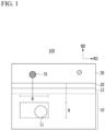
- FIG. 1 is a schematic diagram of a TD cross section of a grain oriented electrical steel sheet according to an embodiment of the present invention.
- a grain oriented electrical steel sheet 100 includes an electrical steel sheet base material 10 and an insulating coating layer 30 positioned on the electrical steel sheet base material 10.
- the insulating coating layer 30 is formed by applying a solvent-containing insulating coating layer forming composition on a steel sheet and then heat-treating the steel sheet. In this case, as the solvent volatilizes at a high temperature, some pores 31 are inevitably formed in the insulating coating layer 30.
- the stress applied to the steel sheet is concentrated under the pore 31 to form a subgrain boundary 11. This has an adverse effect on magnetism compared to Goss crystal grain, which is a main crystal grain of the grain oriented electrical steel sheet, and therefore, is preferably suppressed as much as possible.
- the formation of the subgrain boundary 11 needs to be suppressed as much as possible by analyzing a positional correlation between the pore 31 and the subgrain boundary 11 and the cause of the formation of the subgrain boundary 11.
- FIG. 1 the pore 31 and the subgrain boundary 11 are schematically represented.
- the subgrain boundary 11 exists under the pores 31. All the subgrain boundaries 11 in the steel sheet base material 10 exist in a specific area under the pores 31. However, not all the subgrain boundaries 11 exist under all the pores 31, and there may be the pores 31 having the subgrain boundaries 11 not existing thereunder.
- the electrical steel sheet base material 10 refers to a portion of the grain oriented electrical steel sheet 100 excluding the base coating layer 20 and the insulating coating layer 30.
- the electrical steel sheet base material 10 may contain, by wt%, 2.0 to 7.0% of Si, 0.01 to 0.10% of Sn, 0.01 to 0.07% of Sb, 0.020 to 0.040% of Al, 0.01 to 0.20% of Mn, 0.005% or less of C, 0.005% or less of N, and 0.005% or less of S, and may include the balance of Fe and other in evitable impurities.
- Si serves to reduce core loss by increasing a specific resistance of steel.
- the Si content is too little, the specific resistance of the steel decreases, resulting in poor core loss properties, and secondary recrystallization may be unstable due to the presence of a phase transformation section during secondary recrystallization annealing.
- the Si content may be adjusted within the above range. More specifically, Si may be contained in an amount of 2.5 to 5.0 wt%.
- Sn tin
- Sn is a grain boundary segregation element that hinders grain boundary movement
- Sn promotes the generation of Goss crystal grains having ⁇ 110 ⁇ 001> orientation as a crystal grain growth inhibitor to well develop secondary recrystallization. Therefore, Sn is an important element for reinforcing crystal grain growth inhibitory force.
- the Sn content may be adjusted within the above range. More specifically, Sn may be contained in an amount of 0.02 to 0.08 wt%.
- Antimony is an element that promotes the formation of Goss crystal grains in the ⁇ 110 ⁇ 001> orientation.
- Sb content When the Sb content is too little, a sufficient effect may not be expected as the Goss crystal grain formation promoter, and when the Sb content is too much, Sb is segregated on the surface, so the formation of the oxide layer may be suppressed and the surface defects may occur. Therefore, the Sb content may be controlled within the above range. More specifically, Sb may be contained in an amount of 0.02 to 0.04 wt%.
- Aluminum (Al) is an element that acts as an inhibitor by finally becoming a nitride in the form of AlN, (Al,Si)N, or (Al,Si,Mn)N.
- AlN AlN
- Al,Si Al-based nitrides precipitate and grow too coarsely. Therefore, the Al content may be adjusted within the above range. More specifically, Al may be contained in an amount of 0.020 to 0.030 wt%.
- Manganese (Mn) has the effect of reducing core loss by increasing specific resistance in the same way as Si, and is an element that reacts with nitrogen introduced by nitriding treatment together with Si to form precipitates of (Al,Si,Mn)N, thereby suppressing the growth of primary recrystallized grains and causing the secondary recrystallization.
- Mn content is too much, Mn promotes austenite phase transformation during hot rolling, thereby reducing the size of primary recrystallized grains and making secondary recrystallization unstable.
- Mn content when the Mn content is too little, Mn is an austenite forming element, and increases an austenite fraction during hot-rolling reheating to increase the dissolved content of precipitates, so the effect of preventing primary recrystallized grains from being too excessive through precipitate refinement and MnS formation during re-precipitation may occur insufficiently. Therefore, the Mn content may be adjusted within the above range.
- Carbon (C) is a component that does not greatly help improve the magnetic properties of the grain oriented electrical steel sheet in the embodiment according to the present invention, so C is preferably removed as much as possible.
- C when C is included at a certain level or more, C has an effect of helping to form a uniform microstructure by promoting the austenite transformation of the steel during the rolling process to refine the hot rolled structure during the hot rolling.
- the C content in the slab is preferably contained in an amount of 0.04 wt% or more.
- C may be contained in an amount of 0.07 wt%.
- the decarburization is performed in the primary recrystallization annealing process, and C is contained in an amount of 0.005 wt% or less in the grain oriented electrical steel sheet base material finally manufactured after the decarburization.
- Nitrogen (N) is an element that refines crystal grains by reacting with Al or the like. When these elements are appropriately distributed, as described above, they may be helpful to secure an appropriate primary recrystallized grain size by properly refining the structure after the cold rolling. However, when the content is excessive, the primary recrystallized grains are excessively miniaturized, and as a result, the driving force that causes crystal grain growth during secondary recrystallization increases due to the fine crystal grains, so crystal grains may grow in undesirable orientation. In addition, when the N content is excessive, it is not preferable because it takes a lot of time to remove it in the final annealing process. Therefore, the upper limit of the nitrogen content may be set at 0.005 wt%.
- a nitrogen content may increase due to nitration during the primary recrystallization process.
- the nitrogen content in the slab and the final grain oriented electrical steel sheet base material 10 may be the same.
- the sulfur (S) content exceeds 0.005 wt%, S is re-dissolved and finely precipitated when the hot rolled slab is heated, so a size of primary recrystallized grains is reduced and secondary recrystallization initiation temperature is lowered to deteriorate magnetism.
- the productivity of the grain oriented electrical steel sheet is reduced.
- the S content is as low as 0.005% or less, there is an effect that the initial crystal grain size before the cold rolling is coarsened, so the number of crystal grains having ⁇ 110 ⁇ 001> orientation nucleated in the deformation band in the primary recrystallization process increases. Therefore, it is preferable that the S content is 0.005 wt% or less in order to improve the magnetism of the final product by reducing the size of the secondary recrystal grains.
- the balance includes Fe and inevitable impurities.
- the inevitable impurities are elements that are inevitably added in the manufacturing process of steelmaking and grain oriented electrical steel sheet, and since the inevitable impurities are widely known, descriptions thereof will be omitted.
- the addition of elements other than the above-described alloy components is not excluded, and these elements may be variously contained within a range that does not impair the technical spirit of the present invention. When additional elements are further contained, they are contained in place of Fe which is the balance.
- the subgrain boundary 11 exists in the electrical steel sheet base material 10.
- the subgrain boundary 11 is distinguished from other Goss crystal grains except for the subgrain boundary in that the crystal orientation forms an angle of 1° to 15° from ⁇ 110 ⁇ ⁇ 001>. Specifically, the Goss crystal grains have the crystal orientation less than 1 ° from ⁇ 110 ⁇ ⁇ 001>.
- the crystal orientation is represented by the Miller index.
- the subgrain boundary 11 is positioned under the pores 31. Specifically, the subgrain boundary exists in the area A within 1500 ⁇ m in an RD direction from a center of the pores and an area B within 50 to 100 ⁇ m from the surface of the electrical steel sheet base material toward the inside of the electrical steel sheet base material. In FIG. 1 , the positions defined by the areas A and B are indicated by dotted rectangles. Specifically, all the areas of the subgrain boundary 11 may be included in positions defined as the areas A and B. In an embodiment of the present invention, the subgrain boundary 11 exists only in the above-described area, and the subgrain boundary 11 does not exist in the other part.
- the area fraction of the subgrain boundary in the ND cross section may be 5% or less. When the area fraction of the subgrain boundary 11 is too large, this causes the deterioration in magnetism. More specifically, the area fraction of the subgrain boundary in the ND cross section may be 0.1 to 5%. More specifically, it may be 1 to 3%.
- the ND cross section means a plane perpendicular to the ND direction.
- the particle size of the subgrain boundary 11 is 1 to 500 nm, and it is can be distinguished from the rest of the Goss crystal grains even with the particle size.
- the average particle size of the Goss crystal grains excluding the subgrain boundaries may be 5 to 100 mm. In this case, it is the particle size in the crystal grain ND cross section. More specifically, the particle size of the subgrain boundary 11 may be 10 to 250 nm, and the average particle size of the Goss crystal grains excluding the subgrain boundary may be 10 to 50 mm.
- the ratio L S /L G of the average particle diameter Ls of the subgrain boundary to the average particle diameter L G of the Goss crystal grain in the ND plane may be 0.20 or less. More specifically, it may be 0.10 or less.
- the particle size means a diameter of an imaginary circle having the same area as the corresponding area.
- the electrical steel sheet base material 10 may have a residual stress of 1 to 50 MPa in the RD direction.
- the reason why the residual stress exists in this range is due to the base coating layer 20 and the insulating coating layer 30 existing above the electrical steel sheet base material 10. Due to the presence of the residual stress in the above-described range, the film tension is imparted to the base iron and the magnetism is improved.
- the electrical steel sheet base material 10 may have a residual stress of 16.0 to 30.0 MPa in the RD direction.
- the fine grain interfacial layer 12 may exist from the surface of the electrical steel sheet base material 10 toward the inside of the electrical steel sheet base material.
- the fine grain interfacial layer 12 may have an average grain diameter of 0.1 to 5 ⁇ m.
- the fine grain interfacial layer 12 is formed due to the influence of surface energy non-uniformity.
- a thickness of the fine grain interfacial layer 12 may be 0.1 to 5 ⁇ m. When the fine grain crystal layer 12 is too thick, the magnetism deteriorates, so it is preferable to make the thickness of the fine grain crystal layer 12 thin. More specifically, the thickness of the fine grain interfacial layer 12 may be 0.5 to 3 ⁇ m.
- the fine grain interfacial layer may have a residual stress of -10 to -1000 MPa in a RD direction.
- a negative sign means the stress that the fine grain interfacial layer 12 imparts to the electrical steel sheet base material 10. More specifically, the fine grain interfacial layer 12 may have a residual stress of -10 to -500 MPa in a RD direction. More specifically, the fine grain interfacial layer 12 may have a residual stress of -400 to -500 MPa in a RD direction.
- the grain oriented electrical steel sheet 100 may further include a base coating layer 20 positioned between the electrical steel sheet base material 10 and the insulating coating layer 30.
- the base coating layer 20 forms a coating layer by reacting the oxide layer formed in the primary recrystallization process with components in the annealing separator.
- the base coating layer 20 improves adhesion between the insulating coating layer 30 and the electrical steel sheet base material 10, and also imparts insulation to the grain oriented electrical steel sheet 100 together with the insulating coating layer 30.
- the component of the base coating layer 20 is not particularly limited, but when MgO is included in the annealing separator component, forsterite Mg 2 SiO 4 may be included.
- the base coating layer 20 may be omitted if necessary. That is, the electrical steel sheet base material 10 and the insulating coating layer 30 may be in direct contact with each other.
- a thickness of the base coating layer may be 0.1 to 15 ⁇ m.
- the thickness of the base coating layer 20 may not sufficiently perform the insulating role and the role of improving adhesion to the insulating coating layer 30 described above.
- the base coating layer 20 is too thick, the space factor may decrease, and the adhesion to the insulating coating layer 30 may deteriorate. More specifically, the thickness of the base coating layer 20 may be 0.5 to 3 ⁇ m.
- a residual stress of the base coating layer in the RD direction may be -50 to -1500 MPa. More specifically, the residual stress may be -500 to -1000 MPa. More specifically, the residual stress may be -760 to -1000 MPa.
- the insulating coating layer 30 is positioned on the electrical steel sheet base material 10.
- the insulating coating layer 30 is positioned on the base coating layer 20.
- the insulating coating layer 30 serves to improve core loss by imparting insulation to the grain oriented electrical steel sheet 100 and imparting tension to the electrical steel sheet base material 10.
- the insulating coating layer 30 may use a material capable of imparting insulation to the surface of the electrical steel sheet 100. Specifically, it may include phosphate (H 3 PO 4 ).
- the insulating coating layer 30 is formed by applying a solvent-containing insulating coating layer forming composition on a steel sheet and then heat-treating the steel sheet. In this case, as the solvent volatilizes at a high temperature, some pores 31 are inevitably formed in the insulating coating layer 30.
- the pore 31 means a state in which nothing exists in the corresponding part, that is, an empty space.
- the number of pores having a particle size of 10 nm or more may be 1 to 300 per 1 mm in the RD direction. More specifically, 1 to 30 pores may exist per 1 mm.
- the particle size of the pores may be measured based on the ND plane or the TD plane.
- the number of pores may be measured based on the TD plane.
- subgrain boundary 11 There are 1 to 30 subgrain boundaries per pore with a particle size of 10 nm or more. As described above, the subgrain boundary 11 may not exist in the areas A and B under the pore 31, and it is also possible that two or more subgrain boundaries 11 exist. However, the subgrain boundary 11 may not exist other than the areas A and B under the pores 31.
- a thickness of the insulating coating layer is 0.1 to 15 ⁇ m.
- the thickness of the insulating coating layer 30 is too thin, the above-described insulating role may not be sufficiently performed.
- the base coating layer 30 is too thick, the space factor may decrease, and the adhesion with the electrical steel sheet base material 10 may decrease. More specifically, the thickness of the insulating coating layer 30 may be 1.0 to 5.0 ⁇ m.
- the residual stress of the insulating coating layer 30 in the RD direction is -10 to -1000 MPa. More specifically, the residual stress may be -70 to -500 MPa.
- a method for manufacturing a grain oriented electrical steel sheet according to an embodiment of the present invention includes manufacturing the grain oriented electrical steel sheet; applying an insulating coating layer forming composition on the grain oriented electrical steel sheet; and heat-treating the grain oriented electrical steel sheet to form an insulating coating layer forming composition on the grain oriented electrical steel sheet.
- the grain oriented electrical steel sheet is manufactured.
- the grain oriented electrical steel sheet may use the grain oriented electrical steel sheet in which the base coating layer 20 is formed or not, and only the electrical steel sheet base material 10 exists.
- the grain oriented electrical steel sheet on which the base coating layer 20 is not formed may be manufactured in various ways. For example, a method for adjusting components of an annealing separator, or forming the base coating layer 20 and then removing the base coating layer 20 by physical or chemical methods may be used.
- the method for manufacturing a grain oriented electrical steel sheet according to an embodiment of the present invention may further include: manufacturing a hot rolled sheet by hot rolling a slab; manufacturing a cold rolled sheet by cold-rolling the hot rolled sheet; performing primary recrystallization annealing on the cold rolled sheet; and performing secondary recrystallization annealing on the cold rolled sheet for which the primary recrystallization annealing has been completed.
- the slab may contain 2.0 to 7.0 wt% of Si, 0.01 to 0.10 wt% of Sn, 0.01 to 0.07 wt% of Sb, 0.020 to 0.040 wt% of Al, 0.01 to 0.20 wt% of Mn, 0.04 to 0.07 wt% of C, 10 to 50 wtppm of N, and 0.001 to 0.005 wt% of S, and the balance of Fe and other inevitable impurities.
- the slab is hot-rolled to manufacture the hot rolled sheet.
- a step of heating the slab to 1230°C or less may be further included before the step of manufacturing the hot rolled sheet. Through this step, the precipitate may be partially dissolved.
- the coarse growth of the columnar structure of the slab is prevented, it is possible to prevent cracks from occurring in the width direction of the plate in the subsequent hot rolling process, thereby improving the real yield.
- the slab heating temperature is too high, the melting of the surface of the slab may repair the heating furnace and shorten the life of the heating furnace. More specifically, the slab may be heated to 1130 to 1200°C. It is also possible to hot-roll a continuously cast slab as it is without heating the slab.
- the hot rolled sheet having a thickness of 1.8 to 2.3 mm may be manufactured by hot rolling.
- a step of hot rolled sheet annealing of the hot rolled sheet may be further included.
- the step of annealing the hot rolled sheet may be performed by heating to a temperature of 950 to 1,100°C, cracking at a temperature of 850 to 1,000°C and then cooling.
- the cold rolled sheet is manufactured by cold-rolling the hot rolled sheet.
- the cold rolling may be performed through one-time steel cold rolling or through a plurality of passes. It may give a pass aging effect through warm rolling at a temperature of 200 to 300°C one or more times during rolling, and may be manufactured to a final thickness of 0.14 to 0.25 mm.
- the cold rolled sheet is subjected to decarburization and recrystallization of deformed structure in the primary recrystallization annealing process and nitriding treatment through nitriding gas.
- the cold rolled sheet is subjected to the primary recrystallization annealing.
- the decarburization or nitriding may be performed in the primary recrystallization annealing process.
- the primary recrystallization annealing step may be performed at a temperature of 800 to 900°C. When the temperature is too low, the primary recrystallization may not be performed or the nitriding may not be performed smoothly. When the temperature is too high, the primary recrystallization grows too large, causing the poor magnetism.
- the decarburization it may be performed in an atmosphere having an oxidation capacity (PH 2 O/PH 2 ) of 0.5 to 0.7.
- the steel sheet may contained in an amount of 0.005 wt% or less of carbon, more specifically, 0.003 wt%.
- the annealing separator is applied to the cold rolled sheet for which the primary recrystallization annealing has been completed, followed by secondary recrystallization annealing.
- Various separators may be used as the annealing separator.
- the annealing separator containing MgO as a main component may be applied.
- the base coating layer 20 containing forsterite is formed.
- the purpose of the secondary recrystallization annealing is to form ⁇ 110 ⁇ 001> texture by secondary recrystallization and to remove impurities that harm magnetic properties.
- a mixed gas of nitrogen and hydrogen is maintained to protect nitride, which is a grain growth inhibitor, so the secondary recrystallization may develop well, and after the completion of the secondary recrystallization, it may be maintained for a long time in a 100% hydrogen atmosphere to remove impurities.
- a flattening annealing process may be included.
- the insulating coating layer forming composition is applied on the grain oriented electrical steel sheet.
- the insulating coating layer forming composition may be used in various ways, and is not particularly limited.
- the insulating coating layer forming composition containing phosphate may be used.
- the heat treatment is performed on the grain oriented electrical steel sheet to form the insulating coating layer on the grain oriented electrical steel sheet.
- the solvent volatilizes at a high temperature during the heat treatment process, some pores 31 are inevitably formed in the insulating coating layer 30.
- the stress applied to the steel sheet is concentrated under the pores 31 to form the subgrain boundary 11.
- the formation of the subgrain boundary 11 is inhibited as much as possible by adjusting the tension applied to the steel sheet during the formation of the insulating coating layer.
- the tension applied to the steel sheet in the step of forming the insulating coating layer is 0.20 to 0.70 kgf/mm 2 .
- the tension applied to the steel sheet when the tension applied to the steel sheet is too small, scratches may occur on the surface, resulting in poor corrosion resistance.
- the tension applied to the steel sheet is too large, a large amount of subgrain boundaries 11 may be formed, which may adversely affect magnetism. More specifically, it may be 0.20 to 0.50 kgf/mm 2 . More specifically, it may be 0.3 to 0.47 kgf/mm 2 .
- the tension is the average tension in the longitudinal direction of the steel sheet measured at the exit side of the heat treatment process.
- the tension applied along the longitudinal direction (RD direction) of the steel sheet may be different.
- the residual stress applied to each layer may be appropriately controlled by minimizing the difference between the maximum value MA and the minimum value MI of the tension over the entire length of the steel sheet, and the formation of the subgrain boundary 11 may be inhibited.
- the maximum value MA and the minimum value MI of the tension may satisfy Equation 2 below. MI ⁇ 0.5 ⁇ MA
- Equation 2 When Equation 2 is not satisfied and there is a large deviation in tension along the length direction (RD direction) of the steel sheet, the non-uniformity increases locally, the residual stress is not appropriately controlled, and a large amount of subgrain boundaries 11 are formed.
- the change width in speed change width of a bridle roll and a hearth roll increases according to the change in the line speed, the large deviation in tension may occur in the length direction (RD direction) of the steel plate at high temperature, which is inevitably accompanied during flattening annealing, and the residual stress may not be appropriately controlled due to the local increase in non-uniformity, so the minimum value MI of the tension is inevitably less than 0.5 ⁇ [MA].
- the bridle roll control is a method of controlling feedback tension by following a value of a tension meter. More specifically, it is a method of controlling a speed of a bridle roll to reduce the difference between the maximum value and the minimum value of tension.
- the hearth roll control is a method of controlling feedforward tension following a speed of a bridle roll.
- the tension in order to reduce the difference between the maximum value and the minimum value of the tension, it may be adjusted by controlling the tension to decrease as the speed of the hearth roll increases.
- the tension even if the line speed is varied in the flattening annealing process, it is possible to reduce the difference between the maximum value MA and the minimum value MI while adjusting the tension within a specific range.
- the heat treatment temperature may be 550 to 1100°C. At the above-described temperature, fewer pores 31 are generated, and residual stress of the insulating coating layer 30 may be appropriately applied.
- the cold rolled sheet was maintained in a humid atmosphere of 50v% of hydrogen and 50v% of nitrogen and an ammonia mixed gas atmosphere at a temperature of about 800 to 900°C, and was subjected to decarburization and nitriding annealing heat treatment so that the carbon content was 30 ppm or less and the total nitrogen content increased to 130 ppm or more.
- the steel sheet was applied with MgO as an annealing separator, and finally annealed into a coil shape.
- the final annealing was performed in a mixed atmosphere of 25 v% of nitrogen and 75 v% pf hydrogen up to 1200°C, and after reaching 1200°C, the steel sheet was kept in a 100% hydrogen atmosphere for more than 10 hours and then cooled in a furnace.
- the steel sheet was applied with an insulation coating layer forming composition containing phosphate and silica, and heat-treated at a temperature of about 820°C for 2 hours to form an insulation coating layer.
- the pores, the subgrain boundaries, and other crystal grain characteristics of the manufactured grain oriented electrical steel sheet were summarized in Table 1, and the properties and core loss of the interfacial layer, the base coating layer, and the insulating coating layer were summarized in Table 2.
- the subgrain boundary fraction was measured by an electron backscatter diffraction (EBSD) method for volume per unit area.
- EBSD electron backscatter diffraction
- the core loss W 17/50 and magnetic flux density B 8 were measured immediately after the formation of the insulating coating layer and after heat treatment at 820°C for 2 hours assuming stress relief annealing.
- the core loss was measured under the condition of 1.7 Tesla, 50 Hz using the single sheet measurement method.
- the magnetic flux density induced in a magnetic field of 800 AIm was measured.
- the residual stress of the insulating coating layer was measured using a 3D curvature measuring instrument (ATOS core 45). It was measured by removing only the insulating coating layer on one side and measuring the bending amount of the steel sheet.
- the insulation was measured above the coating using a Franklin measuring instrument according to the ASTM A717 international standard.
- the corrosion resistance indicates an area of rust generated on the surface under the condition of 35°C, 5% NaCL, 8 hours according to JIS Z2371 international standard.
- the diagram below is a film tension calculation method using the radius of curvature (reference M. Bielawski et all., Surf. & Coat. Techno., 200 (2006) 2987).
- the film tension may be calculated from the measured image using the 3D scanner software.
- R values may be measured for specimens before (R2) and after (R1) removal of the phosphate coating layer.
- ⁇ f E s 6 1 ⁇ ⁇ s ⁇ t s 2 t f ⁇ 1 R 2 ⁇ 1 R 1
- the residual stress of the base coating layer and the fine grain interfacial layer was measured using synchrotron XRD equipment.
- the X-ray residual stress measures the peak shift according to a tilting angle ⁇ . Therefore, the X-ray residual stress calculation follows the sin 2 ⁇ method and may be expressed as the following Expression.
- Grain oriented electrical steel sheet 10 Electrical steel sheet base material 11: Subgrain boundary 12: Fine grain interfacial layer 20: Base coating layer 30: Insulating coating layer 31: Pore
Landscapes
- Chemical & Material Sciences (AREA)
- Engineering & Computer Science (AREA)
- Mechanical Engineering (AREA)
- Organic Chemistry (AREA)
- Metallurgy (AREA)
- Materials Engineering (AREA)
- Physics & Mathematics (AREA)
- Crystallography & Structural Chemistry (AREA)
- Thermal Sciences (AREA)
- Manufacturing & Machinery (AREA)
- Electromagnetism (AREA)
- Soft Magnetic Materials (AREA)
- Manufacturing Of Steel Electrode Plates (AREA)
- Chemical Treatment Of Metals (AREA)
Applications Claiming Priority (2)
| Application Number | Priority Date | Filing Date | Title |
|---|---|---|---|
| KR1020200180132A KR102538120B1 (ko) | 2020-12-21 | 2020-12-21 | 방향성 전기강판 및 그의 제조방법 |
| PCT/KR2021/019327 WO2022139352A1 (ko) | 2020-12-21 | 2021-12-17 | 방향성 전기강판 및 그의 제조방법 |
Publications (2)
| Publication Number | Publication Date |
|---|---|
| EP4265747A1 true EP4265747A1 (de) | 2023-10-25 |
| EP4265747A4 EP4265747A4 (de) | 2024-06-26 |
Family
ID=82158285
Family Applications (1)
| Application Number | Title | Priority Date | Filing Date |
|---|---|---|---|
| EP21911419.6A Pending EP4265747A4 (de) | 2020-12-21 | 2021-12-17 | Kornorientiertes elektrostahlblech und herstellungsverfahren dafür |
Country Status (6)
| Country | Link |
|---|---|
| US (1) | US20240035128A1 (de) |
| EP (1) | EP4265747A4 (de) |
| JP (1) | JP7818602B2 (de) |
| KR (1) | KR102538120B1 (de) |
| CN (1) | CN116888284B (de) |
| WO (1) | WO2022139352A1 (de) |
Cited By (1)
| Publication number | Priority date | Publication date | Assignee | Title |
|---|---|---|---|---|
| EP4269651A4 (de) * | 2020-12-22 | 2024-06-19 | POSCO Co., Ltd | Kornorientiertes elektrostahlblech und verfahren zur herstellung davon |
Families Citing this family (2)
| Publication number | Priority date | Publication date | Assignee | Title |
|---|---|---|---|---|
| JPWO2024111637A1 (de) * | 2022-11-22 | 2024-05-30 | ||
| WO2024111638A1 (ja) * | 2022-11-22 | 2024-05-30 | 日本製鉄株式会社 | 方向性電磁鋼板及びその製造方法 |
Family Cites Families (28)
| Publication number | Priority date | Publication date | Assignee | Title |
|---|---|---|---|---|
| JPS6210215A (ja) * | 1985-07-05 | 1987-01-19 | Kawasaki Steel Corp | 超低鉄損一方向性珪素鋼板の製造方法 |
| KR0169734B1 (ko) * | 1989-05-08 | 1999-01-15 | 도오사끼 시노부 | 자기특성이 우수한 1 방향성 규소강판의 제조방법 |
| JP4224957B2 (ja) * | 2001-07-24 | 2009-02-18 | Jfeスチール株式会社 | 下地被膜を有しない方向性電磁鋼板の製造方法 |
| WO2008047999A1 (en) | 2006-10-18 | 2008-04-24 | Posco | Annealing separating agent for grain oriented electrical steel sheet having uniform glass film and excellent magnetic properties and method of manufacturig the same |
| CN101659799B (zh) * | 2009-09-11 | 2012-08-22 | 艾宝魁 | 一种电工钢绝缘涂料,其制备方法及涂覆方法 |
| JP5594240B2 (ja) * | 2010-06-30 | 2014-09-24 | Jfeスチール株式会社 | 方向性電磁鋼板およびその製造方法 |
| JP5754097B2 (ja) | 2010-08-06 | 2015-07-22 | Jfeスチール株式会社 | 方向性電磁鋼板およびその製造方法 |
| BR112013002874B1 (pt) | 2010-08-06 | 2022-05-24 | Jfe Steel Corporation | Chapa de aço elétrica de grão orientado e método para fabricar a mesma |
| CN103025903B (zh) * | 2010-08-06 | 2015-05-06 | 杰富意钢铁株式会社 | 方向性电磁钢板及其制造方法 |
| JP5760504B2 (ja) * | 2011-02-25 | 2015-08-12 | Jfeスチール株式会社 | 方向性電磁鋼板およびその製造方法 |
| JP5729014B2 (ja) | 2011-02-25 | 2015-06-03 | Jfeスチール株式会社 | 方向性電磁鋼板の製造方法 |
| JP5896112B2 (ja) | 2011-10-14 | 2016-03-30 | Jfeスチール株式会社 | 方向性電磁鋼板とその製造方法および変圧器 |
| JP5907257B2 (ja) | 2012-05-24 | 2016-04-26 | Jfeスチール株式会社 | 方向性電磁鋼板の製造方法 |
| JP6156646B2 (ja) | 2013-10-30 | 2017-07-05 | Jfeスチール株式会社 | 磁気特性および被膜密着性に優れる方向性電磁鋼板 |
| KR101568020B1 (ko) * | 2013-12-23 | 2015-11-10 | 주식회사 포스코 | 방향성 전기강판 및 그의 제조방법 |
| KR102177038B1 (ko) * | 2014-11-14 | 2020-11-10 | 주식회사 포스코 | 방향성 전기강판용 절연피막 조성물, 이를 이용하여 표면에 절연피막이 형성된 방향성 전기강판 및 이의 제조방법 |
| KR101651431B1 (ko) * | 2014-11-14 | 2016-08-26 | 주식회사 포스코 | 방향성 전기강판의 제조방법 |
| KR101736627B1 (ko) * | 2015-12-22 | 2017-05-17 | 주식회사 포스코 | 철손이 낮고 절연특성이 우수한 방향성 전기강판 및 그 제조방법 |
| EP3556877B1 (de) * | 2016-12-14 | 2021-01-20 | JFE Steel Corporation | Kornorientiertes elektrisches stahlblech und verfahren zur herstellung davon |
| KR101904308B1 (ko) * | 2016-12-22 | 2018-10-04 | 주식회사 포스코 | 방향성 전기강판용 절연피막 조성물 및 이를 이용한 절연피막 형성방법, 방향성 전기강판 및 방향성 전기강판의 제조 방법 |
| JP6880814B2 (ja) * | 2017-02-21 | 2021-06-02 | 日本製鉄株式会社 | 電磁鋼板、及びその製造方法 |
| WO2018207873A1 (ja) | 2017-05-12 | 2018-11-15 | Jfeスチール株式会社 | 方向性電磁鋼板とその製造方法 |
| RU2726527C1 (ru) * | 2017-07-13 | 2020-07-14 | Ниппон Стил Корпорейшн | Электротехнический стальной лист с ориентированной зеренной структурой |
| JP7031364B2 (ja) | 2018-02-26 | 2022-03-08 | 日本製鉄株式会社 | 方向性電磁鋼板の製造方法 |
| BR112020018664B1 (pt) * | 2018-03-22 | 2024-04-30 | Nippon Steel Corporation | Chapa de aço elétrica com grão orientado e método para produzir a chapa de aço elétrica com grão orientado |
| JP7200687B2 (ja) | 2019-01-16 | 2023-01-10 | 日本製鉄株式会社 | 方向性電磁鋼板及びその製造方法 |
| CN109593927B (zh) * | 2019-02-18 | 2020-09-01 | 安徽工业大学 | 一种采用二次退火生产晶粒取向纯铁的方法 |
| KR102597512B1 (ko) * | 2020-12-22 | 2023-11-01 | 주식회사 포스코 | 방향성 전기강판 및 그의 제조방법 |
-
2020
- 2020-12-21 KR KR1020200180132A patent/KR102538120B1/ko active Active
-
2021
- 2021-12-17 US US18/268,584 patent/US20240035128A1/en active Pending
- 2021-12-17 WO PCT/KR2021/019327 patent/WO2022139352A1/ko not_active Ceased
- 2021-12-17 CN CN202180093870.6A patent/CN116888284B/zh active Active
- 2021-12-17 JP JP2023537560A patent/JP7818602B2/ja active Active
- 2021-12-17 EP EP21911419.6A patent/EP4265747A4/de active Pending
Cited By (1)
| Publication number | Priority date | Publication date | Assignee | Title |
|---|---|---|---|---|
| EP4269651A4 (de) * | 2020-12-22 | 2024-06-19 | POSCO Co., Ltd | Kornorientiertes elektrostahlblech und verfahren zur herstellung davon |
Also Published As
| Publication number | Publication date |
|---|---|
| JP2024503998A (ja) | 2024-01-30 |
| US20240035128A1 (en) | 2024-02-01 |
| CN116888284A (zh) | 2023-10-13 |
| CN116888284B (zh) | 2025-10-14 |
| KR102538120B1 (ko) | 2023-05-26 |
| WO2022139352A1 (ko) | 2022-06-30 |
| KR20220089467A (ko) | 2022-06-28 |
| JP7818602B2 (ja) | 2026-02-20 |
| EP4265747A4 (de) | 2024-06-26 |
Similar Documents
| Publication | Publication Date | Title |
|---|---|---|
| EP3530770B1 (de) | Warmgewalztes stahlblech zur herstellung von elektroblechen und verfahren zur herstellung davon | |
| CN113710822B (zh) | 取向性电磁钢板的制造方法 | |
| EP3960888B1 (de) | Verfahren zur herstellung eines kornorientierten elektrischen stahlblechs | |
| US20200032363A1 (en) | Method for producing grain-oriented electrical steel sheet | |
| EP4265747A1 (de) | Kornorientiertes elektrostahlblech und herstellungsverfahren dafür | |
| KR101351956B1 (ko) | 자성이 우수한 방향성 전기강판 및 그 제조방법 | |
| WO2018117639A1 (ko) | 방향성 전기장판 및 그의 제조방법 | |
| KR101676630B1 (ko) | 방향성 전기강판 및 그 제조방법 | |
| CN116888286B (zh) | 取向性电磁钢板的制造方法 | |
| CN110066908B (zh) | 用于改善高磁感取向硅钢边部晶粒状态的生产方法 | |
| US20250263809A1 (en) | Grain oriented electrical steel sheet and method for manufacturing same | |
| EP4269651A1 (de) | Kornorientiertes elektrostahlblech und verfahren zur herstellung davon | |
| KR101308729B1 (ko) | 자성과 생산성이 우수한 방향성 전기강판의 제조방법 | |
| KR101351955B1 (ko) | 자성이 우수한 방향성 전기강판 및 그 제조방법 | |
| EP0468819B1 (de) | Verfahren zum Herstellen von kornorientierten Siliziumstahlblechen mit verbesserter magnetischer Flussdichte | |
| JPH08134551A (ja) | 鉄損及び磁歪特性の優れた一方向性電磁鋼板の製造方法 | |
| JP2012162773A (ja) | 方向性電磁鋼板の製造方法 | |
| KR101535933B1 (ko) | 방향성 전기강판 및 그 제조방법 | |
| JP2024500443A (ja) | 方向性電磁鋼板およびその製造方法 | |
| JP2023508027A (ja) | 方向性電磁鋼板およびその製造方法 |
Legal Events
| Date | Code | Title | Description |
|---|---|---|---|
| STAA | Information on the status of an ep patent application or granted ep patent |
Free format text: STATUS: THE INTERNATIONAL PUBLICATION HAS BEEN MADE |
|
| PUAI | Public reference made under article 153(3) epc to a published international application that has entered the european phase |
Free format text: ORIGINAL CODE: 0009012 |
|
| STAA | Information on the status of an ep patent application or granted ep patent |
Free format text: STATUS: REQUEST FOR EXAMINATION WAS MADE |
|
| 17P | Request for examination filed |
Effective date: 20230705 |
|
| AK | Designated contracting states |
Kind code of ref document: A1 Designated state(s): AL AT BE BG CH CY CZ DE DK EE ES FI FR GB GR HR HU IE IS IT LI LT LU LV MC MK MT NL NO PL PT RO RS SE SI SK SM TR |
|
| DAV | Request for validation of the european patent (deleted) | ||
| DAX | Request for extension of the european patent (deleted) | ||
| A4 | Supplementary search report drawn up and despatched |
Effective date: 20240529 |
|
| RIC1 | Information provided on ipc code assigned before grant |
Ipc: C22C 38/60 20060101ALI20240523BHEP Ipc: C22C 38/02 20060101ALI20240523BHEP Ipc: C21D 9/46 20060101ALI20240523BHEP Ipc: C21D 6/00 20060101ALI20240523BHEP Ipc: C21D 8/12 20060101AFI20240523BHEP |