EP4262012A1 - Lithiumsekundärbatterie mit zusätzlicher elektrolytlösung - Google Patents
Lithiumsekundärbatterie mit zusätzlicher elektrolytlösung Download PDFInfo
- Publication number
- EP4262012A1 EP4262012A1 EP22899010.7A EP22899010A EP4262012A1 EP 4262012 A1 EP4262012 A1 EP 4262012A1 EP 22899010 A EP22899010 A EP 22899010A EP 4262012 A1 EP4262012 A1 EP 4262012A1
- Authority
- EP
- European Patent Office
- Prior art keywords
- secondary battery
- electrolyte
- lithium secondary
- replenishing unit
- rupture member
- Prior art date
- Legal status (The legal status is an assumption and is not a legal conclusion. Google has not performed a legal analysis and makes no representation as to the accuracy of the status listed.)
- Pending
Links
Images


Classifications
-
- H—ELECTRICITY
- H01—ELECTRIC ELEMENTS
- H01M—PROCESSES OR MEANS, e.g. BATTERIES, FOR THE DIRECT CONVERSION OF CHEMICAL ENERGY INTO ELECTRICAL ENERGY
- H01M50/00—Constructional details or processes of manufacture of the non-active parts of electrochemical cells other than fuel cells, e.g. hybrid cells
- H01M50/60—Arrangements or processes for filling or topping-up with liquids; Arrangements or processes for draining liquids from casings
- H01M50/673—Containers for storing liquids; Delivery conduits therefor
- H01M50/682—Containers for storing liquids; Delivery conduits therefor accommodated in battery or cell casings
-
- H—ELECTRICITY
- H01—ELECTRIC ELEMENTS
- H01M—PROCESSES OR MEANS, e.g. BATTERIES, FOR THE DIRECT CONVERSION OF CHEMICAL ENERGY INTO ELECTRICAL ENERGY
- H01M10/00—Secondary cells; Manufacture thereof
- H01M10/05—Accumulators with non-aqueous electrolyte
- H01M10/052—Li-accumulators
-
- H—ELECTRICITY
- H01—ELECTRIC ELEMENTS
- H01M—PROCESSES OR MEANS, e.g. BATTERIES, FOR THE DIRECT CONVERSION OF CHEMICAL ENERGY INTO ELECTRICAL ENERGY
- H01M10/00—Secondary cells; Manufacture thereof
- H01M10/05—Accumulators with non-aqueous electrolyte
- H01M10/058—Construction or manufacture
-
- H—ELECTRICITY
- H01—ELECTRIC ELEMENTS
- H01M—PROCESSES OR MEANS, e.g. BATTERIES, FOR THE DIRECT CONVERSION OF CHEMICAL ENERGY INTO ELECTRICAL ENERGY
- H01M50/00—Constructional details or processes of manufacture of the non-active parts of electrochemical cells other than fuel cells, e.g. hybrid cells
- H01M50/10—Primary casings; Jackets or wrappings
- H01M50/102—Primary casings; Jackets or wrappings characterised by their shape or physical structure
- H01M50/105—Pouches or flexible bags
-
- H—ELECTRICITY
- H01—ELECTRIC ELEMENTS
- H01M—PROCESSES OR MEANS, e.g. BATTERIES, FOR THE DIRECT CONVERSION OF CHEMICAL ENERGY INTO ELECTRICAL ENERGY
- H01M50/00—Constructional details or processes of manufacture of the non-active parts of electrochemical cells other than fuel cells, e.g. hybrid cells
- H01M50/60—Arrangements or processes for filling or topping-up with liquids; Arrangements or processes for draining liquids from casings
- H01M50/609—Arrangements or processes for filling with liquid, e.g. electrolytes
- H01M50/627—Filling ports
- H01M50/636—Closing or sealing filling ports, e.g. using lids
- H01M50/664—Temporary seals, e.g. for storage of instant batteries or seawater batteries
-
- H—ELECTRICITY
- H01—ELECTRIC ELEMENTS
- H01M—PROCESSES OR MEANS, e.g. BATTERIES, FOR THE DIRECT CONVERSION OF CHEMICAL ENERGY INTO ELECTRICAL ENERGY
- H01M2200/00—Safety devices for primary or secondary batteries
- H01M2200/10—Temperature sensitive devices
-
- Y—GENERAL TAGGING OF NEW TECHNOLOGICAL DEVELOPMENTS; GENERAL TAGGING OF CROSS-SECTIONAL TECHNOLOGIES SPANNING OVER SEVERAL SECTIONS OF THE IPC; TECHNICAL SUBJECTS COVERED BY FORMER USPC CROSS-REFERENCE ART COLLECTIONS [XRACs] AND DIGESTS
- Y02—TECHNOLOGIES OR APPLICATIONS FOR MITIGATION OR ADAPTATION AGAINST CLIMATE CHANGE
- Y02E—REDUCTION OF GREENHOUSE GAS [GHG] EMISSIONS, RELATED TO ENERGY GENERATION, TRANSMISSION OR DISTRIBUTION
- Y02E60/00—Enabling technologies; Technologies with a potential or indirect contribution to GHG emissions mitigation
- Y02E60/10—Energy storage using batteries
Definitions
- the present invention relates to a lithium secondary battery capable of an additional injection of electrolyte.
- a lithium secondary battery has a structure in which a separator is interposed between a positive electrode and a negative electrode as power generation elements, and a liquid electrolyte is injected between the power generation elements.
- a pouch-type battery that is commonly used is manufactured by accommodating an electrode assembly composed of a positive electrode/a separator/a negative electrode in a pouch-type battery case formed by a laminate sheet made of a polymer resin and an aluminum, coupling the upper laminate sheet to the lower laminate sheet in a state in which electrode leads are exposed to both ends of the battery case, and sealing through heat-compression.
- a cell case of a prismatic or a cylindrical lithium-ion secondary battery is made of a metallic material, the cell should be disassembled to inject an additional electrolyte. Due to cell disassembly, an electrode is oxidized in some cases when exposed to air, and there is a disadvantage in that it is difficulty to reseal after an additional injection.
- Korean Open Patent Publication No. 10-2018-0023706 discloses a technology including a sealing member for additional electrolyte injection formed on a part of a battery case, so that an additional injection can be performed and a portion of injection can be sealed after injecting the electrolyte into the electrolyte accommodating part of the battery case, but there are disadvantages in that the assembly process of the battery is complicated due to the sealing member, and that the electrolyte has to be injected for each battery.
- the present invention is to solve the above conventional problems, and in order to extend the lifespan of the secondary battery, the present invention is directed to provide a lithium-ion secondary battery having a novel structure capable of supplying an additional electrolyte when a cell becomes degraded.
- the lithium secondary battery includes: an electrolyte replenishing unit filled with a preliminary electrolyte inside a packaging member; and a rupture member disposed adjacent to the electrolyte replenishing unit and deformed by a temperature change to form a hole in the packaging member so that the preliminary electrolyte inside the electrolyte replenishing unit can be injected.
- the packaging member may be a pouch-type made of a thermoplastic synthetic resin film.
- the packaging member may be made of a polyethylene resin film.
- the electrolyte replenishing unit and the rupture member may be disposed adjacent to an upper surface or a lower surface of the battery case by being stacked on the electrode assembly.
- the electrolyte replenishing unit and the rupture member may be disposed in a sidewall of the battery case of a dead space near the end of the electrode assembly.
- the rupture member may be disposed between the electrolyte replenishing unit and the battery case.
- the rupture member may be thermally deformed at a temperature of 80°C to 120°C.
- the rupture member may be a shape-memory alloy.
- the rupture member may be a bimetal.
- the rupture member may be bonded to the electrolyte replenishing unit, and a weak part may be formed in the packaging member along the edge direction of the rupture member.
- the preliminary electrolyte may not include an additive for SEI film formation.
- the battery case may be a cylindrical metal can or a prismatic metal can.
- the lithium secondary battery electrolyte replenish method includes a step of applying heat to the lithium secondary battery to cause thermal deformation in the rupture member.
- the temperature at which heat is applied to the rupture member may be 80°C to 120°C.
- the lithium secondary battery according to the present invention includes an electrolyte replenishing unit filled with a preliminary electrolyte in case of an electrolyte depletion, and includes a rupture member capable of forming a hole in the electrolyte replenishing unit by being deformed in a predetermined temperature range. Therefore, when capacity deterioration or rapid increase in resistance is observed as a result of repeated charging/discharging of the lithium secondary battery, the rupture member penetrates the surface of the electrolyte replenishing unit through heat treatment of the lithium secondary battery to further replenish the electrolyte inside the electrolyte replenishing unit, thereby having an effect of prolonging secondary battery lifespan.
- the lithium secondary battery according to the present invention has an advantage of not having to disassemble the secondary battery to replenish the electrolyte.
- the lithium secondary battery of the present invention includes an electrode assembly and a main electrolyte inside a battery case.
- An electrode assembly is a power generation element capable of charging and discharging with a laminated structure of a positive electrode/a separator/a negative electrode. It may be any one of a folding type electrode assembly (jelly-roll) in which an active material-coated long sheet-type positive electrode and negative electrode are wound with a separator interposed therebetween, a stack type electrode assembly in which multiple positive electrodes and negative electrodes having a predetermined size are stacked in order with a separator interposed therebetween, a stack/folding type electrode assembly, a stack/lamination type electrode assembly, etc.
- a folding type electrode assembly jelly-roll
- a stack type electrode assembly in which multiple positive electrodes and negative electrodes having a predetermined size are stacked in order with a separator interposed therebetween
- a stack/folding type electrode assembly a stack/lamination type electrode assembly, etc.
- the battery case may be a cylindrical metal can, a prismatic metal can, or a pouch-type battery case made of an aluminum laminated sheet.
- FIG. 1 is a cross-sectional view illustrating a structure of a lithium secondary battery according to an exemplary embodiment of the present invention. It illustrates a pouch-type lithium secondary battery having a form in which a stack type electrode assembly is embedded in a pouch-type battery case made of an aluminum laminated sheet.
- the lithium secondary battery 100 includes: a battery case 60 accommodating an electrode assembly 10 and the electrode assembly 10; an electrolyte replenishing unit 40 filled with a preliminary electrolyte 45 inside a packaging member 41; and a rupture member 50 disposed adjacent to the electrolyte replenishing unit 40 and deformed by a temperature change to form a hole in the packaging member 41 so that the preliminary electrolyte 45 inside the electrolyte replenishing unit 40 can be injected.
- the electrode assembly 10 includes a positive electrode plate 11, a negative electrode plate 12, and a separator 13 interposed between the positive electrode plate 11 and the negative electrode plate 12.
- a positive electrode tab 31 is formed on one side of the positive electrode plate 11, and a negative electrode tab 32 is formed on one side of the negative electrode plate 12, and the positive electrode tab and the negative electrode tab may be arranged side by side at regular spacings.
- the tabs may be connected to an external circuit by being connected to the positive electrode lead 21 and the negative electrode lead 22, respectively.
- the electrode assembly 10, the positive electrode lead 21, and the negative electrode lead 22 are sealed by a pouch-type battery case 60.
- the pouch-type battery case 60 is conventionally a laminated sheet composed of an inner coating layer/a metal layer/an outer layer. By heating and pressurizing a to-be-sealed portion of the upper case and the lower case using a sealing member, inner coating layer of each of the upper case and the lower case is heat-sealed, and thus the inside is sealed.
- part of the positive electrode lead 31 and the negative electrode lead 32 may be sealed by the battery case while being exposed to the outside.
- the lithium secondary battery 100 further includes a main electrolyte 15 in the inside, and the main electrolyte 15 may be an aqueous electrolyte or a non-aqueous electrolyte.
- the aqueous electrolyte may include water and a lithium salt as solvents
- the non-aqueous electrolyte may include a non-aqueous solvent and lithium salt as solvents.
- the non-aqueous solvent may be used without particular limitation as long as it can serve as a medium through which ions involved in the electrochemical reaction of the battery can move through.
- ester-based solvents such as methyl acetate, ethyl acetate, ⁇ -butyrolactone, and ⁇ -caprolactone
- ether-based solvents such as dibutyl ether or tetrahydrofuran
- ketone-based solvents such as cyclohexanone
- aromatic hydrocarbon-based solvents such as benzene, fluorobenzene, etc.
- carbonate-based solvents such as dimethylcarbonate (DMC), diethylcarbonate (DEC), methylethylcarbonate (MEC), ethylmethylcarbonate (EMC), ethylene carbonate (EC), propylene carbonate (PC), etc.
- DMC dimethylcarbonate
- DEC diethylcarbonate
- MEC methylethylcarbonate
- EMC
- carbonate-based solvents are preferred, and cyclic carbonates (e.g., ethylene carbonate or propylene carbonate, etc.) having high ionic conductivity and high dielectric constant capable of increasing the charging/discharging performance of the battery, and a mixture of a low-viscosity linear carbonate-based compounds (e.g., ethyl methyl carbonate, dimethyl carbonate, or diethyl carbonate, etc.) are more preferable.
- cyclic carbonates e.g., ethylene carbonate or propylene carbonate, etc.
- a low-viscosity linear carbonate-based compounds e.g., ethyl methyl carbonate, dimethyl carbonate, or diethyl carbonate, etc.
- the lithium salt may be used without particular limitation as long as it is a compound capable of providing lithium ions used in the lithium secondary battery.
- the lithium salt LiPF 6 , LiClO 4 , LiAsF 6 , LiBF 4 , LiSbF 6 , LiAl0 4 , LiAlCl 4 , LiCF 3 SO 3 , LiC 4 F 9 SO 3 , LiN(C 2 F 5 SO 3 ) 2 , LiN(C 2 F 5 SO 2 ) 2 , LiN(CF 3 SO 2 ) 2 , LiCl, LiI, or LiB(C 2 O 4 ) 2 , etc. can be used.
- the lithium salt is preferably included in the main electrolyte 15 at a concentration of approximately 0.6mol% to 2mol%.
- the main electrolyte may further include one or more of additives such as pyridines, triethylphosphites, triethanolamines, cyclic ethers, ethylene diamines, n-glymes, hexaphosphoric acid triamides, nitrobenzene derivatives, sulfurs, quinone imine dyes, N-substituted oxazolidinones, N,N- substituted imidazolidines, ethylene glycol dialkyl ethers, ammonium salts, pyrroles, 2-methoxy ethanols, or aluminum trichlorides, etc.
- additives such as pyridines, triethylphosphites, triethanolamines, cyclic ethers, ethylene diamines, n-glymes, hexaphosphoric acid triamides, nitrobenzene derivatives, sulfurs, quinone imine dyes, N-substituted oxazolidinones, N,N- substitute
- the main electrolyte solution 15 may include an additive for forming a SEI film such as VC (vinylene carbonate), FEC (fluoro ethylene carbonate), PS (propane sultone), ESA (ethylene sulfite), LiBF 4 , etc.
- VC vinyl carbonate
- FEC fluoro ethylene carbonate
- PS propane sultone
- ESA ethylene sulfite
- the electrolyte replenishing unit 40 is for replenishing an insufficient electrolyte when the main electrolyte is depleted due to repeated charging and discharging of the lithium secondary battery, and it may have a configuration in which a preliminary electrolyte 45 is filled inside a pouch-shaped packaging member.
- the configuration of the electrolyte replenishing unit is not limited thereto.
- the packaging member 41 of the electrolyte replenishing unit 40 is ruptured by a rupture member 50 to be described later when replenishment of the electrolyte is required, allowing the preliminary electrolyte 45 accommodated inside the packaging member 41 to replenish the depleted main electrolyte of the secondary battery.
- the packaging member 41 may be made of a thermoplastic synthetic resin film, preferably made of a polyethylene resin film, because the polyethylene resin film can be easily ruptured by physical pressure.
- the preliminary electrolyte 45 contained in the electrolyte replenishing unit 40 does not include an additive for forming a SEI film. Since the additive for forming a SEI film is added to form the SEI film during the initial charging, the additive for forming a SEI film is not required in the preliminary electrolyte for additional replenishment, and if the additive forming a SEI film is included, it can negatively affect the battery due to a decomposition reaction of its components.
- FIG. 3 is a perspective view showing a structure of a lithium secondary battery according to an exemplary embodiment of the present invention.
- the electrolyte replenishing unit 40 When the electrolyte replenishing unit 40 is formed in a form of a pouch, it can be formed with a large cross-sectional area similar to the electrode assembly 10, so there are advantages in that a sufficient amount of preliminary electrolyte can be contained, and the electrolyte replenishing unit can be formed to have a small thickness.
- the rupture member 50 may be a thermally deformable member that is deformed by heat, and the thermally deformable member is preferably a shape-memory alloy or a bimetal.
- a Shape-memory alloy refers to a metal that causes martensitic transformation, pseudoelasticity, or superelasticity transformation due to stress induction when heat is applied, and a typical example is a nickel-titanium alloy.
- a bimetal is made by attaching two metals with different coefficients of thermal expansion, and based on the fact that each metal has a different coefficient of thermal expansion, it is a substance that has a property of bending to one side due to having a different degree of expansion depending on changes in temperature.
- the upper metal is preferably composed of a first metal having a small coefficient of thermal expansion
- the lower metal is preferably composed of a second metal having a larger coefficient of thermal expansion than that of the first metal.
- the first metal expands relatively little and the second metal greatly expands relatively, so that the bimetal bends in one direction.
- the rupture member 50 may be disposed adjacent to one side of the electrolyte replenishing unit, and this is because when the rupture member 50 is thermally deformed by the heat applied from the outside, and the thermally deformed end part 51 of the rupture member can apply physical pressure to form a hole in the electrolyte replenishing unit 40.
- the rupture member 50 and the electrolyte replenishing unit 40 may simply have a laminated structure or a bonded structure.
- the rupture member 50 and the electrolyte replenishing unit 40 have a simple laminated structure, it is preferable to form a hole by rupturing the packaging member 41 of the electrolyte replenishing unit 40 by the end of the rupture member 50, and in this case, it is preferable to form the end part 51 of the rupture member 50 to be sharp.
- the electrolyte replenishing unit 40 When the rupture member 50 and the electrolyte replenishing unit 40 are bonded together, the electrolyte may be easily leaked by forming a weak part (not illustrated) along the edge direction of the rupture member 50, so that the packaging member may be destroyed along the weak part when the rupture member is thermally deformed.
- the rupture member 50 If a hole can be formed in the packaging member 41 of the electrolyte replenishing unit 40 by the rupture member 50, its shape and size are not particularly limited, and it is preferable to reduce the volume and the weight.
- the rupture member 50 is preferably interposed between the electrolyte replenishing unit 40 and the battery case 60 so that heat can be easily applied from the outside.
- the rupture member is thermally deformed in a temperature range of 80°C to 120°C, preferably 85°C to 110°C.
- thermal deformation of the rupture member occurs at a temperature lower than 80°C, unintended thermal deformation of the rupture member may occur during daily charging and discharging of a lithium secondary battery.
- thermal deformation of the rupture member occurs at a temperature exceeding 120°C, since excessive heat must be applied to the lithium secondary battery to replenish the electrolyte, the battery may be deteriorated or the cycle characteristics of the battery may be adversely affected, resulting in thermal runaway, which is undesirable.
- the electrolyte replenishing unit 40 and the rupture member 50 are disposed in a separation space between the electrode assembly 10 and the battery case 60.
- the electrolyte replenishing unit 40 When the electrolyte replenishing unit 40 is formed as a packaging member 41 in a form of a pouch, it may be stacked on the electrode assembly 10 and disposed adjacent to the upper surface or the lower surface of the battery case 60. In this case, it is preferable because it is possible to efficiently apply heat to the rupture member from the outside.
- the electrolyte replenishing unit 40 and the rupture member 50 may be interposed on a battery case 60 sidewall of a dead space A near the end of the electrode assembly 10.
- the rupture member 50 may have conductivity and may cause an internal short circuit when the rupture member 50 having conductivity comes into contact with the electrode lead, in the case in which the rupture member 50 has conductivity, it is preferable that the electrolyte replenishing unit 40 and the rupture member 50 are stacked on the electrode assembly 10 and disposed adjacent to the upper surface or the lower surface of the battery case 60.
- the electrolyte replenishing method of the lithium secondary battery according to an exemplary embodiment of the present invention may include a step of causing thermal deformation in the rupture member by applying heat to the lithium secondary battery of the present invention.
- FIG. 2 is a cross-sectional view of a lithium secondary battery in which an electrolyte is depleted
- FIG. 3 is a cross-sectional view of a lithium secondary battery in which a preliminary electrolyte of an electrolyte replenishing unit is filled inside the battery.
- the temperature at which heat is applied is preferably in the range of 80°C to 120°C.
- the lithium secondary battery according to the present invention can prolong its lifespan by additionally injecting the preliminary electrolyte stored inside the electrolyte replenishing unit through a heat treatment.
- a stack type electrode assembly was manufactured by stacking 8 basic units of a positive electrode-separator-negative electrode-separator.
- Ethylene carbonate (EC) Ethylmethyl carbonate (EMC) was mixed at a volume ratio of 30:70, and in a non-aqueous organic solvent to which LiPF 6 is dissolved to a concentration of 1.0M, 1.0wt% of vinylene carbonate (VC) and 0.5wt% of propanesultone (PS) were added as SEI film forming additives to prepare the electrolyte.
- EMC Ethylene carbonate
- VC vinylene carbonate
- PS propanesultone
- an electrolyte in which ethylene carbonate (EC): ethylmethyl carbonate (EMC) was mixed in a volume ratio of 30:70, and LiPF 6 was dissolved to a concentration of 1.0 M was prepared.
- a packaging member of the electrolyte replenishing unit As a packaging member of the electrolyte replenishing unit, a pouch-type polyethylene resin film was prepared, and the preliminary electrolyte was filled into the packaging member and was sealed to manufacture the electrolyte replenishing unit.
- a shape-memory alloy that is thermally deformed at 90° C and having an acicular distal end was prepared.
- the electrode assembly, the electrolyte replenishing unit, and the rupture member were accommodated in a pouch-type battery case laminated with PP/Al/Nylon, and the main electrolyte was injected to complete the manufacture of the secondary battery.
- the electrolyte replenishing unit and the rupture member were not accommodated, but a secondary battery in which the electrode assembly and the main electrolyte of the Example were accommodated was manufactured.
- the secondary battery of Experimental Example 1 was charged under 0.33C/4.2V constant current/constant voltage (CC/CV) 4.2V/0.05C conditions at 25°C and discharged at a constant current of 0.33C/2.5V to measure the discharge capacity using PNE-0506 charger/discharger (manufacturer: PNE Solution Co., Ltd., 5V, 6A).
- the measured discharge capacity was defined as the initial capacity.
- Capacity Retention Rate % discharge capacity per cycle / initial capacity ⁇ 100
- the secondary battery of the Experimental Example 2 was charged under 0.33C/4.2V constant current-constant voltage 4.2V/0.05C conditions and discharged at 0.33C using a PNE-0506 charger/discharger (manufacturer: PNE Solution Co., Ltd., 5V, 6A) to adjust the state of charge for the battery to SOC 50%, and the resistance value was obtained by measuring the voltage drop in a state in which a discharge pulse was applied for 10 seconds at a constant current of 2.5C. This was defined as the initial resistance.
- Resistance Increase Rate % resistance according to cycle ⁇ initial resistance / initial resistance ⁇ 100
- the secondary battery of the Experimental Example 3 was heated for 10 minutes at a temperature of 90°C to 100°C. The heating process was not performed on the secondary battery of the Comparative Example.
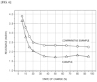
- the secondary batteries of Examples and Comparative Example were adjusted to a charging state as much as 5% of the state of charge (SOC) by charging under 0.33C/4.2V constant current-constant voltage 4.2V/0.05C conditions and discharging at 0.33C.
- the resistance value was obtained by measuring the voltage drop in a state in which a discharge pulse was applied for 10 seconds at a constant current of 2.5C.
- the state of charge is 10%, 15%, 20%, 35%, 50%, 65%, 80%, and 95%
- each resistance value was measured in the same way as above, and the results were shown in FIG. 6 .
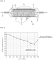
- the battery degrades and the capacity retention rate continuously decreases, and especially at 1200 to 1400 cycles, the capacity retention rate drops from 83% to 75%, so it can be seen that the deterioration of the battery intensifies in the corresponding section.
- the resistance of the lithium secondary battery continuously increases, and especially at 1200 to 1400 cycles, the resistance greatly increases from 40% to 59% compared to the initial resistance, and this is presumed to be due to depletion of the electrolyte inside the lithium secondary battery and deterioration of the active material.
- the electrolyte is additionally injected by the electrolyte replenishing unit at the 1400th cycle, the slope of the capacity retention rate decreased in the subsequent charge/discharge cycles, the resistance increase rate rapidly decreased from 59% to approximately 18%, and no increase in resistance was observed even after performing additional charging and discharging for the subsequent 200 cycles.
- the lithium secondary battery according to the Comparative Example showed greater cell resistance at all state of charge than that of the lithium secondary battery according to the Examples.
- the secondary battery according to the present invention can additionally inject an electrolyte by causing a rupture on the surface of the electrolyte replenishing unit through a high-temperature heat treatment, and accordingly, battery lifespan can be extended.
Landscapes
- Chemical & Material Sciences (AREA)
- Chemical Kinetics & Catalysis (AREA)
- Electrochemistry (AREA)
- General Chemical & Material Sciences (AREA)
- Engineering & Computer Science (AREA)
- Manufacturing & Machinery (AREA)
- Secondary Cells (AREA)
- Filling, Topping-Up Batteries (AREA)
- Sealing Battery Cases Or Jackets (AREA)
Applications Claiming Priority (2)
| Application Number | Priority Date | Filing Date | Title |
|---|---|---|---|
| KR1020210163410A KR20230076463A (ko) | 2021-11-24 | 2021-11-24 | 전해액 추가 주액이 가능한 리튬 이차전지 |
| PCT/KR2022/018571 WO2023096328A1 (ko) | 2021-11-24 | 2022-11-23 | 전해액 추가 주액이 가능한 리튬 이차전지 |
Publications (2)
| Publication Number | Publication Date |
|---|---|
| EP4262012A1 true EP4262012A1 (de) | 2023-10-18 |
| EP4262012A4 EP4262012A4 (de) | 2025-04-16 |
Family
ID=86540032
Family Applications (1)
| Application Number | Title | Priority Date | Filing Date |
|---|---|---|---|
| EP22899010.7A Pending EP4262012A4 (de) | 2021-11-24 | 2022-11-23 | Lithiumsekundärbatterie mit zusätzlicher elektrolytlösung |
Country Status (6)
| Country | Link |
|---|---|
| US (1) | US20240079752A1 (de) |
| EP (1) | EP4262012A4 (de) |
| JP (1) | JP7636093B2 (de) |
| KR (1) | KR20230076463A (de) |
| CN (1) | CN116783773A (de) |
| WO (1) | WO2023096328A1 (de) |
Families Citing this family (1)
| Publication number | Priority date | Publication date | Assignee | Title |
|---|---|---|---|---|
| KR102874013B1 (ko) | 2023-07-28 | 2025-10-20 | 주식회사 엘지에너지솔루션 | 리튬 이차 전지 |
Family Cites Families (11)
| Publication number | Priority date | Publication date | Assignee | Title |
|---|---|---|---|---|
| KR100614394B1 (ko) * | 2004-06-19 | 2006-08-21 | 삼성에스디아이 주식회사 | 전해액 보충 부재를 구비하는 이차 전지 |
| JP2009076249A (ja) | 2007-09-19 | 2009-04-09 | Fuji Heavy Ind Ltd | 蓄電デバイス |
| US8652668B2 (en) * | 2010-02-15 | 2014-02-18 | Sharp Kabushiki Kaisha | Secondary battery; solar power generation system, wind power generation system, and vehicle provided therewith; and method for fabrication of a secondary battery |
| KR101313070B1 (ko) * | 2010-03-23 | 2013-09-30 | 주식회사 엘지화학 | 리튬 이차전지용 케이스 및 이를 포함하는 리튬 이차전지 |
| JP2012243672A (ja) | 2011-05-23 | 2012-12-10 | Nec Corp | リチウムイオン二次電池 |
| KR101651515B1 (ko) * | 2011-10-10 | 2016-08-29 | 주식회사 엘지화학 | 전해액 자동 보충이 가능한 이차전지 |
| KR101459885B1 (ko) * | 2012-03-20 | 2014-11-07 | 주식회사 엘지화학 | 전해액을 포함하는 에어캡을 구비한 파우치형 전지 |
| KR101936074B1 (ko) * | 2015-05-12 | 2019-01-09 | 주식회사 엘지화학 | 전해액 내장 부재를 포함하는 전지셀 |
| KR102145492B1 (ko) * | 2016-06-14 | 2020-08-18 | 주식회사 엘지화학 | 수명 특성이 향상된 전지시스템 및 전지시스템의 가동 방법 |
| KR102031276B1 (ko) | 2016-08-26 | 2019-10-11 | 주식회사 엘지화학 | 이차전지 및 이차전지의 전해액 보충 방법 |
| KR102818246B1 (ko) * | 2020-05-04 | 2025-06-10 | 주식회사 엘지에너지솔루션 | 소화물질을 포함하는 소화부가 구비된 전지 모듈 |
-
2021
- 2021-11-24 KR KR1020210163410A patent/KR20230076463A/ko active Pending
-
2022
- 2022-11-23 CN CN202280010450.1A patent/CN116783773A/zh active Pending
- 2022-11-23 US US18/272,708 patent/US20240079752A1/en active Pending
- 2022-11-23 EP EP22899010.7A patent/EP4262012A4/de active Pending
- 2022-11-23 JP JP2023542780A patent/JP7636093B2/ja active Active
- 2022-11-23 WO PCT/KR2022/018571 patent/WO2023096328A1/ko not_active Ceased
Also Published As
| Publication number | Publication date |
|---|---|
| EP4262012A4 (de) | 2025-04-16 |
| KR20230076463A (ko) | 2023-05-31 |
| US20240079752A1 (en) | 2024-03-07 |
| CN116783773A (zh) | 2023-09-19 |
| WO2023096328A1 (ko) | 2023-06-01 |
| JP2024503475A (ja) | 2024-01-25 |
| JP7636093B2 (ja) | 2025-02-26 |
Similar Documents
| Publication | Publication Date | Title |
|---|---|---|
| US10431827B2 (en) | Nonaqueous electrolyte secondary battery | |
| CN101595591B (zh) | 用于可再充电的锂离子电池的n-氧化物氧化还原梭 | |
| US10109889B2 (en) | Non-aqueous electrolyte secondary battery | |
| CN112368873B (zh) | 具有增强的检测低电压能力的二次电池激活方法 | |
| US20190013543A1 (en) | Nonaqueous electrolyte secondary battery | |
| JP6346178B2 (ja) | 非水電解質二次電池 | |
| CN101180762A (zh) | 用于可再充电锂离子电池的取代吩噻嗪氧化还原梭 | |
| JP2017059393A (ja) | 非水電解質電池及び電池パック | |
| EP3745521B1 (de) | Elektrodenanordnung von stapel/falt-typ und diese enthaltende lithiumbatterie | |
| US20160056463A1 (en) | Non-aqueous electrolyte secondary battery | |
| CN103329333B (zh) | 非水电解液充电电池 | |
| WO2015001719A1 (ja) | 非水電解質二次電池 | |
| WO2015079893A1 (ja) | リチウム二次電池 | |
| JP2004311442A (ja) | リチウム二次電池用電解質及びこれを含むリチウム二次電池 | |
| JP2002208434A (ja) | 非水性電解液の再充電可能な電気化学電池のための有機カーボネート添加剤 | |
| EP4262012A1 (de) | Lithiumsekundärbatterie mit zusätzlicher elektrolytlösung | |
| CN111386622B (zh) | 圆筒形二次电池 | |
| JP4854208B2 (ja) | 密閉型電池およびその製造方法 | |
| JP2000040526A (ja) | 二次電池用非水電解液及び非水電解液二次電池 | |
| KR101549169B1 (ko) | 전해액이 내장된 캡슐을 포함하는 전기화학소자 | |
| EP3204969B1 (de) | Sekundärbatteriesystem mit wasserfreiem elektrolyt sowie fahrzeug | |
| JP2005243336A (ja) | 渦巻状電極群を備えた電池 | |
| JP2000348759A (ja) | 非水電解液およびそれを用いた二次電池 | |
| JP7282205B2 (ja) | 短絡誘導部材を含む電気化学素子及びそれを用いた安全性評価方法 | |
| JP2012104372A (ja) | 密閉型電池及びその製造方法 |
Legal Events
| Date | Code | Title | Description |
|---|---|---|---|
| STAA | Information on the status of an ep patent application or granted ep patent |
Free format text: STATUS: THE INTERNATIONAL PUBLICATION HAS BEEN MADE |
|
| PUAI | Public reference made under article 153(3) epc to a published international application that has entered the european phase |
Free format text: ORIGINAL CODE: 0009012 |
|
| STAA | Information on the status of an ep patent application or granted ep patent |
Free format text: STATUS: REQUEST FOR EXAMINATION WAS MADE |
|
| 17P | Request for examination filed |
Effective date: 20230713 |
|
| AK | Designated contracting states |
Kind code of ref document: A1 Designated state(s): AL AT BE BG CH CY CZ DE DK EE ES FI FR GB GR HR HU IE IS IT LI LT LU LV MC ME MK MT NL NO PL PT RO RS SE SI SK SM TR |
|
| DAV | Request for validation of the european patent (deleted) | ||
| DAX | Request for extension of the european patent (deleted) | ||
| A4 | Supplementary search report drawn up and despatched |
Effective date: 20250318 |
|
| RIC1 | Information provided on ipc code assigned before grant |
Ipc: H01M 10/058 20100101ALI20250312BHEP Ipc: H01M 50/105 20210101ALI20250312BHEP Ipc: H01M 10/052 20100101ALI20250312BHEP Ipc: H01M 50/664 20210101ALI20250312BHEP Ipc: H01M 50/682 20210101AFI20250312BHEP |
|
| GRAP | Despatch of communication of intention to grant a patent |
Free format text: ORIGINAL CODE: EPIDOSNIGR1 |
|
| STAA | Information on the status of an ep patent application or granted ep patent |
Free format text: STATUS: GRANT OF PATENT IS INTENDED |
|
| INTG | Intention to grant announced |
Effective date: 20251210 |
|
| P01 | Opt-out of the competence of the unified patent court (upc) registered |
Free format text: CASE NUMBER: UPC_APP_0000261_4262012/2026 Effective date: 20260106 |
|
| GRAS | Grant fee paid |
Free format text: ORIGINAL CODE: EPIDOSNIGR3 |
|
| GRAA | (expected) grant |
Free format text: ORIGINAL CODE: 0009210 |
|
| STAA | Information on the status of an ep patent application or granted ep patent |
Free format text: STATUS: THE PATENT HAS BEEN GRANTED |