EP4259397B1 - Bretterpaar, holzverbundplatte und verfahren zu deren herstellung - Google Patents
Bretterpaar, holzverbundplatte und verfahren zu deren herstellung Download PDFInfo
- Publication number
- EP4259397B1 EP4259397B1 EP21830926.8A EP21830926A EP4259397B1 EP 4259397 B1 EP4259397 B1 EP 4259397B1 EP 21830926 A EP21830926 A EP 21830926A EP 4259397 B1 EP4259397 B1 EP 4259397B1
- Authority
- EP
- European Patent Office
- Prior art keywords
- boards
- pairs
- profiles
- pair
- another
- Prior art date
- Legal status (The legal status is an assumption and is not a legal conclusion. Google has not performed a legal analysis and makes no representation as to the accuracy of the status listed.)
- Active
Links
Images


Classifications
-
- B—PERFORMING OPERATIONS; TRANSPORTING
- B27—WORKING OR PRESERVING WOOD OR SIMILAR MATERIAL; NAILING OR STAPLING MACHINES IN GENERAL
- B27D—WORKING VENEER OR PLYWOOD
- B27D1/00—Joining wood veneer with any material; Forming articles thereby; Preparatory processing of surfaces to be joined, e.g. scoring
- B27D1/04—Joining wood veneer with any material; Forming articles thereby; Preparatory processing of surfaces to be joined, e.g. scoring to produce plywood or articles made therefrom; Plywood sheets
-
- B—PERFORMING OPERATIONS; TRANSPORTING
- B27—WORKING OR PRESERVING WOOD OR SIMILAR MATERIAL; NAILING OR STAPLING MACHINES IN GENERAL
- B27M—WORKING OF WOOD NOT PROVIDED FOR IN SUBCLASSES B27B - B27L; MANUFACTURE OF SPECIFIC WOODEN ARTICLES
- B27M3/00—Manufacture or reconditioning of specific semi-finished or finished articles
- B27M3/0013—Manufacture or reconditioning of specific semi-finished or finished articles of composite or compound articles
- B27M3/0026—Manufacture or reconditioning of specific semi-finished or finished articles of composite or compound articles characterised by oblong elements connected laterally
- B27M3/0053—Manufacture or reconditioning of specific semi-finished or finished articles of composite or compound articles characterised by oblong elements connected laterally using glue
-
- B—PERFORMING OPERATIONS; TRANSPORTING
- B27—WORKING OR PRESERVING WOOD OR SIMILAR MATERIAL; NAILING OR STAPLING MACHINES IN GENERAL
- B27M—WORKING OF WOOD NOT PROVIDED FOR IN SUBCLASSES B27B - B27L; MANUFACTURE OF SPECIFIC WOODEN ARTICLES
- B27M3/00—Manufacture or reconditioning of specific semi-finished or finished articles
- B27M3/0013—Manufacture or reconditioning of specific semi-finished or finished articles of composite or compound articles
- B27M3/0026—Manufacture or reconditioning of specific semi-finished or finished articles of composite or compound articles characterised by oblong elements connected laterally
-
- B—PERFORMING OPERATIONS; TRANSPORTING
- B27—WORKING OR PRESERVING WOOD OR SIMILAR MATERIAL; NAILING OR STAPLING MACHINES IN GENERAL
- B27M—WORKING OF WOOD NOT PROVIDED FOR IN SUBCLASSES B27B - B27L; MANUFACTURE OF SPECIFIC WOODEN ARTICLES
- B27M3/00—Manufacture or reconditioning of specific semi-finished or finished articles
- B27M3/04—Manufacture or reconditioning of specific semi-finished or finished articles of flooring elements, e.g. parqueting blocks
- B27M3/06—Manufacture or reconditioning of specific semi-finished or finished articles of flooring elements, e.g. parqueting blocks of composite floor plates per se by assembling or jointing the parqueting blocks
Definitions
- the invention relates to a pair of boards made of two boards connected to one another along their longitudinally profiled narrow sides with the features of the preamble of claim 1.
- the invention further relates to a wood composite panel comprising at least one layer of pairs of boards connected to one another at their profiled longitudinal narrow sides.
- the invention also relates to methods for producing the aforementioned pairs of boards and wood composite panels.
- Multi-layer composite panels made of cross laminated timber or sawn timber are known from the state of the art.
- Multi-layer composite panels made of cross laminated timber also known under the English name "cross laminated timber” are currently made exclusively from softwood and are preferably made up of three layers, usually glued together crosswise. Individual layers can also be replaced by other wood materials such as particle boards (OSB boards) or laminated veneer lumber.
- OSB boards particle boards
- laminated veneer lumber laminated veneer lumber
- Single-layer or multi-layer wood composite panels offer the advantage that they can be manufactured as a large-format "carpet" from which components with any surface dimensions can then be sawn or divided.
- the individual boards are arranged lengthways and glued together along their narrow sides in a press.
- the press must apply a "surface pressure” to the visible surfaces of the boards connected to one another and usually also a “side pressure” to the narrow sides of the outermost boards of the board assembly.
- the format of the carpet that can be produced is therefore limited to the size of the press, in particular its maximum pressing width.
- a pair of boards according to the invention comprising two boards connected to one another along their longitudinally profiled narrow sides, wherein the profiling is preferably a profiling already carried out in the sawmill when the boards are fresh, is characterized in that the boards originate from the same tree trunk, preferably from the same tree trunk cut to a standard raw wood length, with essentially the same moisture content and conicity and are cut from mutually corresponding layers of the tree trunk that are opposite one another with respect to a longitudinal axis of the tree trunk, wherein a guide bevel is formed on the boards to be connected, wherein the two boards have been connected when the boards are fresh and wherein the two boards are arranged in a neutral annual ring position with respect to one another.
- Such a pair of boards is for example in Fig. 6 and is described in more detail below. It is clear from the boards of the pair of boards, even when they are connected to one another after production, that the boards were profiled when fresh and come from opposite sides of the same tree trunk. The profiling when fresh can be seen from the shrinkage behavior. The fact that the boards come from the same tree opposite each other can be seen from their very similar density, a similar annual ring pattern with essentially the same pattern of annual ring widths, the same moisture content, the same quality and distance of the branch formation in the annual growth, and the same shrinkage behavior.
- These properties can be inspected or measured comparatively, for example, on the front surface (also known in technical jargon as the "braid surface” because it is on the side of the trunk facing the treetop) and the stock surface (the stock surface is opposite the front surface, i.e. it faces the rootstock of the tree trunk) of the boards.
- the front surface also known in technical jargon as the "braid surface” because it is on the side of the trunk facing the treetop
- the stock surface the stock surface is opposite the front surface, i.e. it faces the rootstock of the tree trunk
- the two boards of the pair of boards were joined together when the boards were still fresh.
- the boards are joined together when they are still fresh in the sawmill and come from the same trunk and from the same, opposite layer in the tree trunk, they have essentially the same quality, conicity and, in particular, roughly the same moisture content as a natural product.
- the same or at least very similar moisture content of the two boards is a prerequisite for effective bonding when they are still wet, e.g. with PU adhesive, whereby bonding with PU adhesive can be supported in the process by using microwave devices and/or other measures for surface heating.
- the boards can also be two narrow side boards, whereby by joining these narrow side boards together when they are still fresh in the sawmill, a wider pair of boards is immediately obtained.
- the pair of boards is provided with parallel guide bevels on its two narrow longitudinal sides.
- the two boards are arranged in a neutral annual ring position in relation to one another.
- the matching boards can thus be arranged in a neutral annual ring position, which complies with the craft rule for solid wood, which is to arrange the boards to be joined in a neutral annual ring position, which leads to neutral shrinkage and swelling of the boards joined together without tension and/or warping.
- Arranging in a neutral annual ring position means that adjacent boards are arranged in such a way that the annual ring sections of the boards are arranged next to each other in opposite curvatures. This is visible on the pair of boards on the front and the stock side.
- the boards show conformal shrinkage and swelling ("negative shrinkage"), so that over the service life of the pair of boards, not such great stresses arise in the adhesive connections.
- the known higher quality of side boards i.e. boards that have been cut from the tree side, e.g.
- the profiles of the boards at the common longitudinal connection are designed as complementary dovetail profiles, the longitudinal connection optionally being provided with an adhesive, and preferably, when several dovetail profiles are formed on each board, adjacent dovetail connections are formed inversely to each other. For example, when several dovetail profiles are formed on each board, adjacent Dovetail joints for each board thickness of approx. 10 mm (multiple thickness) are designed in reverse to each other.
- the dovetail profiles are preferably milled in the curve of the tree edge.
- sorting in relation to more or less wane or portioning of adhesive can already be carried out during the profiling of the boards in order to produce a fully glued connection without wane, that is the tree bark edge, to form the pair of boards for the visible surfaces, or, for example, for certain low qualities, such as middle layers, less adhesive can be used when the boards have a small wane, or the boards can be connected only by pushing the dovetail profiles of the boards into one another.
- Such qualities can be used as middle layers for the composite panels, in particular for cross-laminated timber.
- each board of the pair of boards is expediently at least 30, preferably at least 40 mm at its narrow end, whereby the board width is preferably as large as possible, e.g. selectable in 1 mm increments.
- the 30 mm minimum width is measured from the point at which the board is at least touched by the saw.
- the board width is at least 80 mm and is stepped in at least 20 mm increments.
- boards with tree edges could hardly be used in the prior art. This meant that only thin side boards could be produced, which is why, in order to make better use of the tree trunk, especially with larger diameters, two side boards were usually cut from each side of the tree trunk, i.e.
- the invention makes it possible to produce conical side boards with the slanted tree edge in greater thickness. This in turn means that the individual side boards can be produced much thicker than conventionally, in particular at least twice as thick as conventionally, and thus of higher quality, and in addition the conventional sawing joint is avoided, thus increasing the yield, and that thicker pairs of boards can be produced from the thicker boards by means of form-fitting dovetail joints, preferably while still fresh, without twisting or shrinkage.
- the boards are profiled in relation to one another without overlapping and the guide bevels are designed as stops for the formation of further dovetail profiles for connecting pairs of boards using the dovetail profiles at the longitudinal connections.
- the advantage of this embodiment is that it is possible to produce wooden panels of any width without a press from these pairs of boards. These wooden panels can be extended, preferably in predetermined system widths, by finger jointing as more stable structural timbers connected by at least one adhesive joint and can be used for longitudinal, middle and transverse layers or for visible or cover layers for wood composites.
- each board has a guide bevel incorporated when fresh and the pair of boards has been profiled on its longitudinal narrow sides with complementary folding profiles when dry, preferably with an overlap of 0.3 to 0.6 mm.
- a wood composite panel produced from such pairs of boards connected to one another on their longitudinal narrow sides is characterized by the fact that adjacent pairs of boards are arranged in a neutral annual ring position.
- the pairs of boards are laid in a layer width in a neutral annual ring position according to the craft rule and pushed through the press in time with the width of a press, preferably a high-frequency press, in a continuous flow with a short pressing time. From this "endless" wood composite panel, wood composite panels of any width can be cut as required, e.g. in system widths of 250, 500, 750, 1000, 1250, 2500 mm, and then further processed.
- the pairs of boards of a respective layer are provided with adhesive on their profiles and adhesive is applied to the surfaces of adjacent layers of pairs of boards, with the pairs of boards of a respective layer being arranged parallel to one another.
- the layers of the wood composite panel can be pressed together in the same work step by applying surface pressure to the outer layers. and connected to each other, whereby a panel width can be produced in the cycle width of the press, ie in the feed length of the press.
- the wood composite panel produced in this way is already fully bound and practically produced in a continuous process, whereby by laying the pairs of boards of the same layers parallel to each other and applying adhesive to the feed table, a further cycle width is already available ready for further pressing in a continuous process in order to produce endless panels, as in Fig. 4 From these panels, the desired width of the wood composite panel can be cut from the endless wood composite panel as required.
- a suitable embodiment of the wood composite panel according to the invention has at least three superimposed layers of pairs of boards according to the invention, wherein the pairs of boards of a respective layer are provided with adhesive on their profiles and adhesive is applied to the surfaces of adjacent layers of pairs of boards, wherein the pairs of boards of adjacent layers are arranged crosswise to one another.
- the invention also relates to a method for producing a pair of boards, which is characterized by cutting two boards from the same tree trunk, preferably from the same tree trunk cut to a standard raw wood length, in the fresh state of the tree trunk from mutually corresponding layers of the tree trunk that are opposite one another with respect to a longitudinal axis of the tree trunk, forming profiles on at least one of the longitudinal narrow sides of the boards in the fresh state of the boards, arranging the two boards so that the boards are mirrored to one another with respect to a central transverse axis, and connecting the boards of the longitudinal narrow sides by sliding them into one another along their profiles, preferably in the fresh state of the boards, optionally with prior application of adhesive to the profiles.
- the pair of boards is provided with parallel guide bevels on its two narrow longitudinal sides and the two boards are arranged in a neutral annual ring position in relation to each other.
- the boards are profiled without overlapping in relation to one another, that the guide bevels with stop are used for the formation of the dovetail profiles and further for controlled guidance on the continuously inserted guide bevel on the stop for sliding into one another without offset and deviations.
- each board is provided with a guide bevel in the fresh state and the pairs of boards are profiled on their longitudinal narrow sides 5 with complementary folding profiles in the dry state, preferably with 0.3 to 0.6 mm overlap of the folding profiles.
- a preferred embodiment of the pair of boards according to the invention is characterized in that the geometry of the dovetails in the tangential wood of the annual rings in the round tree edge at the root of the tails, preferably in a minimum width of 6 mm, is designed with greater strength for greater loading by transverse forces, with the central dovetails being approximately twice as high as the laterally outer dovetails in the curve of the tree edge.
- the central dovetails with the extended flanks have head heights of approximately 4.5 mm, 6 mm or 8 mm
- the laterally outer dovetails have head heights of approximately 2 mm, 2.5 mm, 3 mm or 4 mm.
- the dovetails in the standing wood of the radial annual rings in the trapezoidal center plank e.g. the trapezoidal boards Z with Z ⁇ , see Fig. 15 , at the root about 3 mm wide and about 2 mm high, the boards can be connected by dovetails in a preferably grid of e.g. 10 mm as a multiple thickness to at least one pair of boards from the wedge-shaped center plank Z with Z ⁇ again in parallel form.
- the method according to the invention for producing wood composite panels provides for the production of multi-layer wood composite panels which have at least two layers, in which the pairs of boards are arranged in at least two layers on top of each other and connected to one another, with the pairs of boards in each layer being arranged parallel to one another and the adjacent layers being glued together in the same work step.
- These wood composite panels can be produced with very little adhesive and are therefore environmentally friendly.
- shrinkage/swelling, especially at the adhesive joints, is reduced even later, when installed, and the neutral annual ring position means that only little or no stress is created at the slanted connections on the long side walls (which are formed from the tree edges). This also applies to the surface bonding of adjacent layers on pairs of boards, for which homogeneous side boards with their relatively flat annual rings are ideally suited.
- multi-layered wood composite panels in panel width or in predefined required widths or system width are to be connected to one another by means of a finger joint, whereby the wood composite panels are layered in at least two layers, whereby the boards are first sorted in raw wood length to produce the pairs of boards without any knots or parts of the boards with knots are cut off, and whereby the multi-layered wood composite panels are cut into glued squared timbers.
- the finger joint can be subjected to a standardized tensile test so that the squared timbers can be used as long, stable beams/supports with assured quality.
- Figure 1 shows a cross-sectional view of a section of a single-layer wood composite panel 1 according to the invention according to a first embodiment.
- the wood composite panel 1 is made of several boards 2 placed next to one another, the side boards of a block-shaped substrate 3 (see Fig. 6 ), for example a raw round wood.
- the boards 2 originate from the same tree trunk, preferably from the same tree trunk cut to a standard raw wood length, and are cut from corresponding layers of the tree trunk that are opposite one another with respect to a longitudinal axis of the tree trunk.
- the boards 2 have a trapezoidal cross-section, with longitudinal narrow sides 5 forming the legs of the trapezoidal cross-section, and with adjacent boards 2 arranged mirrored to one another with respect to a central transverse axis 6.
- the boards 2 are connected to one another with essentially the same wood fiber direction along their longitudinal narrow sides 5 profiled in the longitudinal direction 4.
- the outer visible surfaces of the boards 2 connected to one another form an upper side 7 and a lower side 8 of the wood composite panel 1.
- the boards 2 have a board thickness 11.
- the longitudinal direction 4 is in accordance with Figure 1 normal to the sheet plane.
- Two boards 2 are connected to form a pair of boards 14 (see Fig. 3 ). By placing the pairs of boards 14 next to one another, a surface of boards 2 that is essentially infinitely long in the transverse direction, a so-called "carpet”, can be provided only by applying surface pressure, ie without additional lateral pressure.
- the boards are profiled along their longitudinal direction 4 on the longitudinal narrow sides 5, whereby the profiling is preferably a profiling that has already been carried out in the sawmill when the boards 2 are still fresh.
- the profile of the longitudinal narrow sides 5 has a folding profile 9 with a folding profile angle SW of less than or equal to 90 degrees, in the present example according to Figure 1 in about 60 degrees.
- the folding profiles 9, as in Figure 1 shown be offset from the central transverse axis 6.
- the distance from the central transverse axis 6 can be approximately 0.1 mm to 0.8 mm, preferably approximately 0.3 mm to 0.6 mm, particularly preferably approximately 0.4 mm to 0.5 mm.
- This overlap 12 can - according to the previously mentioned examples for the distance from the central transverse axis 6 - be approximately 0.1 mm to 0.8 mm, preferably approximately 0.3 mm to 0.6 mm, particularly preferably approximately 0.4 mm to 0.5 mm.
- the profile of the longitudinal narrow sides 5 can have more than one folding profile 9, preferably two folding profiles 9, wherein the folding profile angle SW of all folding profiles 9 is less than or equal to 90
- the folding profile angles SW of the folding profile 9 or of all folding profiles 9 are, for example, 80 degrees or less, preferably 70 degrees or less.
- Figure 2 shows a cross-sectional view of a section of a single-layer wood composite panel 10 according to the invention according to a second embodiment.
- the wood composite panel 10 according to the second embodiment is essentially the same as the wood composite panel 1 according to the first embodiment, with the difference that two adjacent boards 2 are joined along their longitudinal narrow sides 5 in contact with one another via a dovetail profile 13 to form a pair of boards 14 (see Fig. 3 ) are connected to each other.
- the boards 2 to be joined together to form pairs of boards 14 can be equipped with two or more than two, for example three, four or five, dovetail profiles 13.
- each pair of boards 14 After connecting the adjacent boards 2 to form a pair of boards 14 (see Figures 3 to 6 ), each pair of boards 14 has a profile with a guide bevel 17 along its outer longitudinal narrow sides 5 (see Fig. 5A ) or a folding profile 9 with a folding profile angle SW of less than or equal to 90 degrees, in the present example according to Figure 2 approximately 60 degrees. For folding profile angles SW of less than 80 degrees, a supplementary hooking effect is created.
- the pair of boards 14 is also made from two boards 2 connected to one another along their longitudinal narrow sides 5 profiled in the longitudinal direction 4, whereby the boards 2 come from the same tree trunk and are cut from corresponding layers of the tree trunk that are opposite one another in relation to a longitudinal axis of the tree trunk.
- the profiling is preferably already produced in the sawmill when the boards 2 are still fresh.
- the boards 2 are arranged opposite one another in a mirrored manner in relation to a central transverse axis 6.
- the boards 2 are side boards of a pair of boards 14 from the same trunk layer of a raw round timber (see Figure 6 ) and connected to each other via a dovetail profile 13.
- the pair of boards 14 has a substantially rectangular and stable shape, for example according to the Figures 3A to 3D , without the risk of bending.
- a substantially infinite surface in the transverse direction a so-called "carpet" can be provided which forms a wood composite panel 10, 20 or 30.
- the folding profiles 9 prevent the boards 2 from being pushed apart transversely to the direction of the pressing force, i.e. essentially transversely to the existing direction of action of the surface pressure FD. Any overhangs 12 that may have existed before pressing are deformed and "ironed out” by the action of the pressing force, so that a flat and parallel top 7 and bottom 8 are created.
- the profiling of the boards 2 is carried out in such a way that an overhang 12 between adjacent boards 2 only occurs due to the dimensioning of the folding profile 9.
- the single-layer wood composite panel 10 can alternatively be designed as a two-layer wood composite panel 20, a three-layer wood composite panel 30 or as a wood composite panel with more than three layers, for example four, five, six, seven, eight, nine, ten or more than ten layers.
- the top side 7 of the wood composite panel 10, 20 or 30 is formed from the outer visible surfaces of the uppermost layer of pairs of boards 14 made of interconnected boards 2 and the bottom side 8 of the wood composite panel 10, 20 or 30 is formed from outer visible surfaces of the lowermost layer of pairs of boards 14 made of interconnected boards 2.
- a middle layer panel 15 can be formed from side boards, middle boards, middle planks, squared timber planks, cross timber planks and/or center planks of a block-shaped substrate 3. It should also be mentioned that the thickness of the individual layers of the wood composite panels can be relatively small, eg only 20 mm thick. Such thin layers are called lamellas, which are processed into multilayer panels that have high rigidity and strength. It has been shown that the quality of these multilayer panels is higher if pairs of boards are used instead of individual boards.
- Fig. 5A and Fig. 5B show two boards 2 joined together to form a pair of boards 14, for example that according to Figure 3 , in a mixed perspective view, wherein the dovetail profile 13 for connecting the boards 2 is shown inserted.
- the boards 2 are profiled without overlapping with respect to each other, and the Guide bevels 17 serve as stops for the formation of further dovetail profiles for connecting pairs of boards 14 by means of the dovetail profiles at the longitudinal connections 13.
- Figure 6 shows a method for producing such a pair of boards 14 from boards 2.
- the method is particularly efficient and can be carried out cost-effectively.
- the two boards 2 represent a "right" and a "left" side board of a block-shaped substrate 3, for example a raw round timber, as described above.
- the two boards 2 are sawn in a fresh state from the same log layer of the substrate 3.
- One of the boards 2 is then turned and the longitudinal narrow sides 5 of the boards 2 to be connected are each profiled with opposite dovetail profiles 13, the boards 2 being guided along a guide bevel direction 16 at the stop of guide bevels 17 which are milled into the boards 2.
- the profiling of the boards 2 preferably takes place when the boards 2 are still fresh.
- the boards 2 are then connected, while still wet, with or without PU adhesive to form the pair of boards 14 by pushing the complementary partners of the dovetail profiles 13 into one another.
- the pushing of the boards 2 into one another takes place at a relative speed to one another, ie the boards 2 can be moved in opposite directions, or one of the boards 2 can be stationary, or the boards 2 are moved in the same direction at different speeds.
- the bonding on the longitudinal narrow sides 5 can be optimized by using microwaves to promote a uniform reaction in the adhesive joint.
- Each pair of boards 14 is connected along its center and can be profiled on the remaining outer longitudinal narrow sides 5 with one or more folding profiles 9.
- the pairs of boards 14 are preferably dried.
- Optional storage of the pairs of boards 14 in a warm/heated environment supports the reaction in the adhesive joint.
- the fact that the boards were profiled and joined when fresh can be seen from the shrinkage behavior.
- the fact that the boards come from the same tree opposite each other can be determined by analysis, e.g. based on their very similar branch formation in the branch pattern of the board surfaces with the distances of the annual growth, their comparable density, similar annual ring patterns with almost the same annual ring widths, the same moisture and the same quality as is usual in a tree trunk, and comparable shrinkage behavior.
- the dovetail connection creates a positive connection between the boards 2.
- the two boards 2 of the board pair 14 are arranged in a neutral annual ring position with respect to one another.
- each board 2 at its narrow end, at least as cut by the saw is at least 30, preferably at least 40 mm, wherein the board width is preferably as large as possible, e.g. selectable in 1 mm increments.
- a method according to the invention for producing a wood composite panel 1, 10, 20 or 30 is described below by way of example:
- a first method step several boards 2 are provided.
- two adjacent boards 2 of the provided boards are made of the same block-shaped substrate 3 and are cut in particular while the substrate 3 is still fresh, which is preferably a tree trunk cut to a standard raw wood length, and are joined together to form pairs of boards 14 as described above.
- each board 2 is profiled while still fresh along its longitudinal narrow sides 5 with profiles which, according to the above description, have at least one dovetail profile 13 and/or one or more folding profiles 9 with a folding profile angle SW of less than or equal to 90 degrees.
- pairs of boards 14 are provided, the boards 2 of these pairs of boards 14 are connected to one another along their longitudinal narrow sides 5 which are in contact with one another via at least one dovetail profile 13, and the pairs of boards 14 are each profiled along their outer longitudinal narrow sides 5 with a profile which, according to the above description, has one or more folding profiles 9 with a folding profile angle SW of less than or equal to 90 degrees.
- the folding profiles 9 can be milled, whereby preferably on the longitudinal narrow sides 5 in the wider area of the board 2 or pair of boards 14 a narrow edge is first pre-milled as a guide bevel 17, which can subsequently serve as a stop for the milling process of the folding profiles 9 (see Figure 6 ).
- the dovetail profiles 13 and the folding profiles 9 must be present in the finished products at all times.
- the profiling of the boards 2 is carried out on their longitudinal narrow sides 5 using circular saw blades with bevel grinding, e.g. with a bevel grinding of 15 degrees both for the production of dovetail profiles and folding profiles 9 with folding profile angles SW of 15 or 75 degrees.
- pairs of boards 14 are arranged mirrored to one another with respect to the central transverse axis 6 and are glued together in a press under the influence of surface pressure FD on the top side 7 and/or the bottom side 8 of the wood composite panel 1, 10.
- the so-called "carpet" formed in this way can essentially be produced to an infinite length.
- Pairs of boards 14 can also be placed on top of one another in several layers by applying adhesive to their mutually facing top and bottom surfaces and then pressed together by surface pressure. What is new compared to the prior art is that this production process can be carried out in just one step.
- the pairs of boards 14 of the wood composite panel which are connected to one another at their longitudinal narrow sides 5, are aligned such that adjacent pairs of boards 14 are arranged in a neutral annual ring position.
- the process steps described can be repeated as often as required to produce further layers.
- the layers are preferably placed parallel to one another and glued together to form a wood composite panel 20 or 30.
- the surfaces of the layers formed can be glued together in the rough sawn state, i.e. without prior surface smoothing, if a suitable press is used, e.g. a press that provides pressure compensation by filling it with oil.
- the wood composite panel 1, 10, 20 or 30 produced as described above can be cut to length in width along at least one sawing direction, preferably essentially parallel to the longitudinal narrow sides 5.
- the cut wood composite panel 1, 10, 20 or 30 can be glued and/or galvanized to other wood composite panels along its width narrow sides 18.
- the production of a wood composite panel 1, 10, 20 or 30 according to the methods described above enables previously unattainable low production costs and high yields.
- the production of wood composite panels 1, 10, 20 or 30 according to the invention is preferably carried out using a high-frequency press, with subsequent dividing and/or finger-jointing enabling the manufacture of a wide variety of products, for example single- or multi-layer cross-laminated timber panels, or beams for wood construction.
- FIG. 7 and Fig. 8 Another embodiment of a single-layer wood composite panel 50 according to the invention is shown in cross section.
- the wood composite panel 50 consists of Boards 22, whereby two boards 22 are combined to form a pair of boards 24 and adjacent pairs of boards 24 are connected to one another.
- the term "board” as used herein also includes “planks", which are boards with greater thicknesses.
- the boards 22 have profiles in the form of dovetails 13 along their longitudinal narrow sides 5, whereby the dovetail profiles 13 of adjacent boards 22 facing one another are designed to be complementary to one another, so that by pushing the dovetail profiles 13 into one another, two boards 22 are connected to one another to form a pair of boards 24.
- the boards 22 have a trapezoidal cross-section transverse to their longitudinal extent, in which the longitudinal narrow sides form the legs of the trapezoidal cross-section, whereby the boards 22 are arranged mirrored to one another with respect to a central transverse axis 6.
- Fig. 7 Overlaps of the boards 22 on some of the dovetail profiles 13, but this wood composite panel 50 can also be manufactured without overlaps, as can be seen from the embodiments according to Fig. 9A and Fig. 9B shown.
- each pair of boards 24 have at least one dovetail profile 13, wherein the dovetail profiles 13 are shaped such that the dovetail profiles 13 formed on the outer longitudinal narrow sides 5 complement each other when connecting adjacent pairs of boards 24, or in other words are formed oppositely or complementarily.
- the dovetail profiles 13 on the longitudinal narrow sides 5 of the facing boards 22 of each pair of boards can be spaced apart from the central transverse axis 6 by about 0.1 mm to 0.8 mm, preferably by about 0.3 mm to 0.6 mm, particularly preferably by about 0.4 mm to 0.5 mm, whereby an overlap is produced when the adjacent boards 22 are connected on the facing longitudinal narrow sides 5.
- This overlap is leveled out by surface pressing of the pair of boards 24, whereby the dovetail profiles 13 wedge into each other and thus a better connection is created.
- the boards 22 are connected to each other in a moist, i.e. undried, state.
- the external dovetail joints 13 of the pairs of boards 24 are not offset from the central transverse axis 6. This saves the use of a press when connecting pairs of boards 24. However, it is preferable, e.g. for load-bearing applications, to only connect dry pairs of boards 24 to one another. This is not an embodiment of the invention and is described here only for the purpose of illustration.
- the inventive Wood composite panel 50 also the outer longitudinal narrow sides 5 of the pair of boards 24 by about 0.1 mm to 0.8 mm, preferably about 0.3 mm to 0.6 mm, particularly preferably about 0.4 mm to 0.5 mm, from the central transverse axis 6, whereby when adjacent pairs of boards 24 are connected on the mutually facing narrow longitudinal sides 5, an over-thrust results which is leveled out by pressing using a press.
- a single-layer wood composite panel 50 according to the invention is shown, in which the connecting dovetail profiles 13 can be produced at the tree edge of side boards as well as in boards and planks from the whole trunk at an angle of 25° to 90°, e.g. with the measurement data of the boards 22 and/or the pairs of boards 24.
- the wood composite panel can be divided, preferably in the fresh state, into standard widths (shown in dashed lines as exemplary widths A, B, C), e.g. in a 2 cm grid, whereby wood composite elements are provided in the grid 6, 8, 10, 12, 14, 16, ... up to about 40 cm.
- the wood composite panel 50 is preferably divided lengthwise approximately in the middle of the width of the boards 22, which can be followed by a drying process.
- wood composite panels and the pairs of boards according to the invention can be subjected to additional processing steps depending on the intended use, in particular a calibration of their thickness to the same thickness by planing, milling and/or grinding.
- a three-layer wood composite panel 60 according to the invention is shown in cross-section, which is composed of three single-layer wood composite panels 50 arranged one above the other by means of adhesive bonding.
- the single-layer wood composite panels 50 are similar to those of the Figures 7 and 8 , with the difference that none of the dovetail profiles 13 is spaced from the central transverse axis 6 and therefore has no overlap.
- the overlap-free wood composite panels 50 already have the required formats for the wood composite panel 60 and can be placed on top of one another and glued together without any problems, without a remaining board that has to be cut off and protrudes at the edge of the wood composite panel 60.
- the middle wood composite panel 50 is arranged transversely (crosswise) to the outer wood composite panels 50, whereby the three-layer wood composite panel 60 forms a cross-laminated timber. Multi-layer wood composite panels 60 with five, seven, nine, etc. layers can also be produced as cross-laminated timber.
- the top side 7 of the top single-layer wood composite panel 50 and the bottom side 8 of the bottom single-layer wood composite panel 50 represent the outer visible surfaces of the three-layer wood composite panel 60.
- the middle single-layer wood composite panel 50 can cost-effectively consist of side boards, middle boards, middle planks, squared timber planks, cross timber planks and/or center planks of a block-shaped substrate 3.
- Fig. 9B shows a variant of the wood composite panel 60 from Fig. 9A , in which the boards of each pair of boards are connected to one another by folding profiles 9 instead of dovetail profiles 13.
- the pressing of the wood composite panel 60 can be carried out in one work step.
- Fig. 10 shows a cross-section of a board 2 that has been cut as a thick side board from a substrate 3, namely a tree trunk in the fresh state.
- the tree trunk has a stock end 3a, a middle 3b and a sapling 3c, which is the top end.
- the cross-section of the board 2 comes from the middle 3b of the tree trunk.
- the board 2 has been provided with a folding profile 9 on the left at its wane edges WK (which are also referred to as tree edges and represent that part of the board on the circumference of the tree) and with several dovetail profiles 13 on the right, with adjacent dovetail joints 13 being formed in reverse to one another.
- WK wane edges
- WK which are also referred to as tree edges and represent that part of the board on the circumference of the tree
- two rectangular boards 30, 31 have been drawn in a thin line within the board, as they would be in cutting processes according to the state of the art as side boards with a wide kerf between the boards 30, 31 and a lot of sawdust next to the boards 30, 31.
- Fig. 11 shows in cross-section another board 2, which has been cut as a thick side board from a substrate 3, namely a tree trunk in the fresh state.
- This board 2 differs from the board 2 of Fig. 10 only by the fact that several dovetail profiles 13 are milled into the forest edges on the left and right.
- Fig. 12 shows in cross-section another board 2, which has been cut as a thick side board from a substrate 3, namely a tree trunk in the fresh state.
- This board 2 corresponds to the board 2 of Fig. 11 , wherein it is demonstrated that in the case of thick tree trunks and correspondingly wide boards 2, the board 2 can be divided lengthwise by longitudinal cuts along cutting lines 2d, 2e, so that an inner board 2a with a rectangular cross-section and smooth side surfaces and two edge boards 2b, 2c are obtained, each of which has a wane as a side surface into which several dovetail profiles are milled.
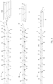
- Fig. 13 shows a cross-section of a pair of boards 14 made up of two boards 2 connected to one another by two dovetail profiles 13 which are formed inversely to one another and into which a guide bevel 17 is milled on their outer side edges, the two guide bevels 17 being aligned parallel to one another.
- a preferred design of the dovetail connection for thinner side boards of e.g. 20, 25, 30 mm is shown, where a mechanical form fit with frictional connection can be established by designing the root to be wider and particularly in the middle and also at the head height. A difference in the head height can also be formed at the designable length of the wedge bevel as shown, with the connection on the pair of boards being shown by a folding profile to the plate.
- the advantage of the inverted design of dovetail profiles according to the invention is also that breaking off or splintering of dovetail parts in the groove at the more acute dovetail corner can be avoided.
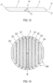
- Fig. 14 shows a front view of a tree trunk seen from the top side, from which it can be seen that according to the invention several side boards S1, S2, S3, S4 and side boards S1', S2 ⁇ , S3', S4 ⁇ are cut off opposite these in the same position with respect to the central axis M of the tree trunk.
- the longitudinal cut of the side boards S1, S2, S3, S4, S1', S2 ⁇ , S3', S4 ⁇ is made parallel to the shell, so that each side board has a constant thickness.
- a central plank Z remains with a thickness that increases over its length.
- the opposite side boards S1 and S1', S2 and S2 ⁇ , S3 and S3', S4 and S4 ⁇ form joining partners, which are joined together to form pairs of boards after profiles have been formed on their wane edges WK.
- the wane edges WK which form the side surfaces of the side boards, are at different, sometimes very acute angles to the base and the top surface of the side boards, whereby the top surfaces on the outer side boards S4, S4 ⁇ are less conically tapered, almost parallel and also have a similar wane at the top (pointed) and stock (steep), which allows maximum yield to be achieved.
- the wane, or conical taper of a tree is the reduction in the diameter of a trunk towards the tree crown.
- top surfaces on the other boards S3, S2, S1 are also less conical than in the state of the art. This reduces the creation of cheaper sawmill by-products (chipped wood and wood chips for the paper or wood-based materials industry) by at least a third. In processing according to the state of the art, such side boards were considered inferior due to their slanted side surfaces. According to the invention, however, they represent a High quality wood raw material for the production of pairs of boards and wood composite panels.
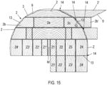
- Fig. 15 shows a cutting pattern through a substrate 3 in the form of a fresh tree trunk, e.g. with a diameter of at least 40 cm at the top, the cutting pattern being shown from the outside to the central plank Z of the tree trunk, but the lower half of the cutting pattern, which is not shown, being symmetrical to the upper half of the cutting pattern.
- a thick side board 2 has first been cut off, the outside (forest edge side) side surfaces of which are preferably profiled on one side with several oppositely identical dovetail profiles 13 while the cut board 2 is still fresh, and on the other side with a folding profile 9.
- the drawing shows how this board 2 is joined to a board 2' cut in the same position from the opposite side of the central axis M of the tree trunk and also provided with dovetail profiles 13 and a folding profile 9 to form a pair of boards 14 by inserting the two boards 2 into each other in the longitudinal direction with their dovetail profiles 13.
- the two boards 2 have been arranged in a neutral annual ring position in accordance with the craft rule, ie that the curvature lines of the annual rings of the two boards 2 run opposite to each other.
- This uppermost cut-off side board 2 corresponds to the one shown in Fig. 10 shown side board 2.
- a second side board 2 is cut off, which is profiled on both sides of the forest edge with dovetail profiles 13.
- This side board 2 corresponds to that of Fig. 11 . Since this side board 2 is already very wide, it is divided lengthwise twice to obtain narrower side boards 2b, 2c and a middle board (heartwood plank) 2a.
- Fig. 15 also shows how the outer side board 2c can be joined with a board 2b ⁇ cut off in the same position from the opposite side of the central axis M of the tree trunk and also provided with dovetail profiles 13 in a neutral annual ring position from board 2c with board 2b to form a pair of boards 14 containing predominantly sapwood 2b'.
- a third board 2 closer to the center is already so wide that it can be divided into a total of five boards, with three planks or battens as central boards.
- a central plank Z is cut out of the substrate 3, which contains the wedge-shaped heartwood in the central axis M.
- This central plank Z is divided, for example, into a total of nine boards in trapezoidal form Z1, Z2, Z3, Z4, Z1', Z2 ⁇ , Z3', Z4 ⁇ , whereby in Fig.
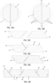
- Fig. 16A to 16F show the production of pairs of boards and the resulting composite wood panels from thin tree trunks, so-called weak wood, in a schematic representation.
- the thin tree trunk is divided lengthwise into two halves, which form the two - almost semi-circular - boards 2, 2.
- a core wedge, such as in the embodiment of Fig. 15 is not formed during division.
- guide bevels 17 are formed along the length of the boards 2, 2.
- dovetail profiles 13 are formed in both boards 2, 2 along the length of the boards 2, 2, see Fig. 16B .
- Fig. 16A dovetail profiles 13 are formed in both boards 2, 2 along the length of the boards 2, 2, see Fig. 16B .
- the left board 2 is turned around its transverse axis and then rotated lengthwise by 90° clockwise.
- the right board 2 is not turned, but is also rotated lengthwise by 90° clockwise.
- the dovetail profiles 13 of the two boards 2, 2 face each other.
- the two boards 2, 2 are pushed into each other lengthwise at the dovetail joints 13, whereby the two interconnected boards 2, 2 form the board pair 14.
- the joining can, but does not have to, be done with the help of glue. Pressure application after pushing into each other is not necessary.
- further dovetail profiles 13 are formed on the slanted long sides of the pair of boards 14.
- the pair of boards 14 can be connected lengthwise with other similar pairs of boards 14 to form a wood composite panel 1 of any width by pushing the pairs of boards 14 into each other at the dovetail profiles, optionally with the aid of glue. Pressure can be applied after joining, but is not necessary.
- the wood composite panel 1 produced in this way is in Fig. 16F It can be seen that both the boards 2 of each pair of boards 14 and the adjacent pairs of boards 14 are each arranged in a neutral annual ring position.
- Fig. 17A to 17F show the production of pairs of boards and the resulting wood composite panels from thin tree trunks, so-called weak wood, in a schematic representation.
- the steps of the production process according to Fig. 17A to 17D correspond to those of Fig. 16A to 16D
- folding profiles 9 are formed on the slanting longitudinal sides of the pair of boards 14 instead of dovetail profiles.
- the pair of boards 14 can be connected lengthwise with other similar pairs of boards 14 to form a wood composite panel 1 of any width by hooking the pairs of boards 14 into each other at the folding profiles, optionally with the aid of glue, and then applying surface pressure.
- the wood composite panel 1 produced in this way is in Fig. 17F It can be seen that both the boards 2 of each pair of boards 14 and the adjacent pairs of boards 14 of the composite wood panel 1 are arranged in a neutral annual ring position. The boards 2 and pairs of boards 14 are joined together when the wood is still fresh.
- FIG. 18A to 18E is the production of a pair of boards according to Fig. 13
- two boards 2 are cut from a tree trunk as side boards by cutting parallel to the mantle, whereby the boards are cut at corresponding, opposite layers of the tree trunk with respect to a longitudinal axis of the tree trunk, see Fig. 18E .
- Guide bevels 17 are formed on the side surfaces of the boards 2, see Fig. 18A
- a dovetail profile 13 is milled on one side surface of each board 2, see Fig. 18B .
- a board 2 (in the drawing the left board 2) is rotated around its longitudinal axis by 180°.
- the two boards 2,2 are thus in opposite, ie neutral annual ring position and with dovetail profiles facing each other, see Fig. 18C Now the two boards 2, 2 are pushed together lengthwise at their dovetail profiles 13 while still fresh, i.e. wet, and thus form the pair of boards, as shown in Fig. 18D shown.
Landscapes
- Engineering & Computer Science (AREA)
- Life Sciences & Earth Sciences (AREA)
- Manufacturing & Machinery (AREA)
- Wood Science & Technology (AREA)
- Forests & Forestry (AREA)
- Mechanical Engineering (AREA)
Applications Claiming Priority (2)
| Application Number | Priority Date | Filing Date | Title |
|---|---|---|---|
| ATA51083/2020A AT524491A1 (de) | 2020-12-14 | 2020-12-14 | Bretterpaar, Holzverbundplatte und Verfahren zu deren Herstellung |
| PCT/AT2021/060478 WO2022126169A1 (de) | 2020-12-14 | 2021-12-14 | Bretterpaar, holzverbundplatte und verfahren zu deren herstellung |
Publications (2)
| Publication Number | Publication Date |
|---|---|
| EP4259397A1 EP4259397A1 (de) | 2023-10-18 |
| EP4259397B1 true EP4259397B1 (de) | 2025-02-12 |
Family
ID=79024693
Family Applications (1)
| Application Number | Title | Priority Date | Filing Date |
|---|---|---|---|
| EP21830926.8A Active EP4259397B1 (de) | 2020-12-14 | 2021-12-14 | Bretterpaar, holzverbundplatte und verfahren zu deren herstellung |
Country Status (7)
| Country | Link |
|---|---|
| EP (1) | EP4259397B1 (pl) |
| AT (1) | AT524491A1 (pl) |
| DK (1) | DK4259397T3 (pl) |
| FI (1) | FI4259397T3 (pl) |
| LT (1) | LT4259397T (pl) |
| PL (1) | PL4259397T3 (pl) |
| WO (1) | WO2022126169A1 (pl) |
Family Cites Families (8)
| Publication number | Priority date | Publication date | Assignee | Title |
|---|---|---|---|---|
| FR2469279A1 (fr) * | 1979-11-14 | 1981-05-22 | Degut Andre | Panneau compose pour la realisation notamment de volets, portes, fenetres, et de meubles en general |
| DE3216669A1 (de) * | 1982-05-04 | 1983-11-10 | Peter 2057 Reinbek Polaczek | Verfahren zur verarbeitung von rundholz zu konstruktionsholz bzw. furnieren und vorrichtung zur durchfuehrung des verfahrens |
| DE4135247A1 (de) * | 1991-10-25 | 1993-04-29 | Berthold Fries | Konstruktions-bauhoelzer und verfahren zu deren herstellung |
| US20020160147A1 (en) * | 2001-02-27 | 2002-10-31 | Suezone Chow | Composite wood product and method of manufacture |
| FI20061039A0 (fi) * | 2006-11-27 | 2006-11-27 | Johan Tore Karlstroem | Menetelmä pitkänomaisen puukomposiittituotteen tuottamiseksi ja pitkänomainen puukomposiittituote |
| AT13575U1 (de) * | 2012-11-05 | 2014-04-15 | Hans-Peter Leitinger | Holzverbundplatte |
| PL2821191T3 (pl) * | 2013-07-02 | 2016-03-31 | Gerhard Weissteiner | Element płytowy z drewna |
| AT515171B1 (de) * | 2013-12-10 | 2016-02-15 | Hans-Peter Ing Leitinger | Schnittholzplatte aus Seitenbrettware sowie Verfahren zu deren Herstellung |
-
2020
- 2020-12-14 AT ATA51083/2020A patent/AT524491A1/de not_active Application Discontinuation
-
2021
- 2021-12-14 WO PCT/AT2021/060478 patent/WO2022126169A1/de not_active Ceased
- 2021-12-14 EP EP21830926.8A patent/EP4259397B1/de active Active
- 2021-12-14 FI FIEP21830926.8T patent/FI4259397T3/fi active
- 2021-12-14 PL PL21830926.8T patent/PL4259397T3/pl unknown
- 2021-12-14 DK DK21830926.8T patent/DK4259397T3/da active
- 2021-12-14 LT LTEPPCT/AT2021/060478T patent/LT4259397T/lt unknown
Also Published As
| Publication number | Publication date |
|---|---|
| PL4259397T3 (pl) | 2025-06-23 |
| DK4259397T3 (da) | 2025-05-12 |
| LT4259397T (lt) | 2025-05-26 |
| FI4259397T3 (fi) | 2025-05-19 |
| WO2022126169A1 (de) | 2022-06-23 |
| AT524491A1 (de) | 2022-06-15 |
| EP4259397A1 (de) | 2023-10-18 |
Similar Documents
| Publication | Publication Date | Title |
|---|---|---|
| AT522641A1 (de) | Bretterpaar, Holzverbundplatte und Verfahren zu deren Herstellung | |
| DE3936312C2 (pl) | ||
| EP3797984B1 (de) | Verfahren zur herstellung eines holzbauelementes sowie holzbauelement | |
| EP2569154A1 (de) | Mehrschichtiger furnierholz-formkörper | |
| EP1486627A1 (de) | Grossformatige OSB-Platte mit verbesserten Eigenschaften, insbesondere für den Baubereich | |
| DE2947611A1 (de) | Verfahren zur herstellung von brettlamellen aus rundholz | |
| DE102009006971B4 (de) | Verfahren zur Herstellung eines BSH-Lamellenträgers | |
| WO2014068039A1 (de) | Holzverbundplatte | |
| EP3224040A1 (de) | Steg, sandwich-platte, sandwich-block sowie deren herstellungsverfahren | |
| SE1550853A1 (en) | Method of producing a laminated wood product, and laminated wood products | |
| EP4259397B1 (de) | Bretterpaar, holzverbundplatte und verfahren zu deren herstellung | |
| EP1721714B1 (de) | Balkenbinder aus Holz | |
| DE202013006624U1 (de) | Brettsperrholz aus Keilbohlen | |
| EP3042744A1 (de) | Lamellen aus naturholz, damit gefertigte bretter, balken und platten | |
| DE102015010118A1 (de) | Verfahren zur Herstellung von Holzbauteilen | |
| DE202019002463U1 (de) | Trägerelement für Decken, Zwischendecken, Ständergewerken und dgl. | |
| AT516697A1 (de) | Lamellen aus Naturholz, damit gefertigte Bretter, Balken und Platten | |
| EP4570495A1 (de) | Parkettdiele und verfahren zu deren herstellung | |
| DE102011054165B4 (de) | Verfahren zur Herstellung von Keilbohlen | |
| WO1997044168A1 (de) | Holz-rohling, verfahren zum herstellen desselben und anlage zur durchführung des verfahrens | |
| AT525323B1 (de) | Holzverbundprodukt | |
| DE102024001322A1 (de) | Werkstück mit einer Keilzinkenanordnung sowie Verfahren zur Herstellung solcher Werkstücke | |
| WO2022028654A1 (de) | Verfahren zum herstellen von konstruktionsbauholz aus schwachholz und konstruktionsbauholz | |
| DE4316369C2 (de) | Verfahren zur Herstellung von Tafelelementen | |
| DE102017113368A1 (de) | Mehrschichtplatte und Verfahren zu ihrer Herstellung |
Legal Events
| Date | Code | Title | Description |
|---|---|---|---|
| STAA | Information on the status of an ep patent application or granted ep patent |
Free format text: STATUS: UNKNOWN |
|
| STAA | Information on the status of an ep patent application or granted ep patent |
Free format text: STATUS: THE INTERNATIONAL PUBLICATION HAS BEEN MADE |
|
| PUAI | Public reference made under article 153(3) epc to a published international application that has entered the european phase |
Free format text: ORIGINAL CODE: 0009012 |
|
| STAA | Information on the status of an ep patent application or granted ep patent |
Free format text: STATUS: REQUEST FOR EXAMINATION WAS MADE |
|
| 17P | Request for examination filed |
Effective date: 20230613 |
|
| AK | Designated contracting states |
Kind code of ref document: A1 Designated state(s): AL AT BE BG CH CY CZ DE DK EE ES FI FR GB GR HR HU IE IS IT LI LT LU LV MC MK MT NL NO PL PT RO RS SE SI SK SM TR |
|
| DAV | Request for validation of the european patent (deleted) | ||
| DAX | Request for extension of the european patent (deleted) | ||
| GRAP | Despatch of communication of intention to grant a patent |
Free format text: ORIGINAL CODE: EPIDOSNIGR1 |
|
| STAA | Information on the status of an ep patent application or granted ep patent |
Free format text: STATUS: GRANT OF PATENT IS INTENDED |
|
| INTG | Intention to grant announced |
Effective date: 20240423 |
|
| GRAJ | Information related to disapproval of communication of intention to grant by the applicant or resumption of examination proceedings by the epo deleted |
Free format text: ORIGINAL CODE: EPIDOSDIGR1 |
|
| STAA | Information on the status of an ep patent application or granted ep patent |
Free format text: STATUS: REQUEST FOR EXAMINATION WAS MADE |
|
| GRAP | Despatch of communication of intention to grant a patent |
Free format text: ORIGINAL CODE: EPIDOSNIGR1 |
|
| STAA | Information on the status of an ep patent application or granted ep patent |
Free format text: STATUS: GRANT OF PATENT IS INTENDED |
|
| INTG | Intention to grant announced |
Effective date: 20240903 |
|
| GRAS | Grant fee paid |
Free format text: ORIGINAL CODE: EPIDOSNIGR3 |
|
| GRAA | (expected) grant |
Free format text: ORIGINAL CODE: 0009210 |
|
| STAA | Information on the status of an ep patent application or granted ep patent |
Free format text: STATUS: THE PATENT HAS BEEN GRANTED |
|
| AK | Designated contracting states |
Kind code of ref document: B1 Designated state(s): AL AT BE BG CH CY CZ DE DK EE ES FI FR GB GR HR HU IE IS IT LI LT LU LV MC MK MT NL NO PL PT RO RS SE SI SK SM TR |
|
| RAP3 | Party data changed (applicant data changed or rights of an application transferred) |
Owner name: LEITINGER, HANS-PETER |
|
| REG | Reference to a national code |
Ref country code: GB Ref legal event code: FG4D Free format text: NOT ENGLISH |
|
| RIN1 | Information on inventor provided before grant (corrected) |
Inventor name: LEITINGER, HANS-PETER |
|
| REG | Reference to a national code |
Ref country code: CH Ref legal event code: EP |
|
| REG | Reference to a national code |
Ref country code: DE Ref legal event code: R096 Ref document number: 502021006646 Country of ref document: DE |
|
| REG | Reference to a national code |
Ref country code: IE Ref legal event code: FG4D Free format text: LANGUAGE OF EP DOCUMENT: GERMAN |
|
| REG | Reference to a national code |
Ref country code: DK Ref legal event code: T3 Effective date: 20250506 |
|
| REG | Reference to a national code |
Ref country code: FI Ref legal event code: FGE |
|
| REG | Reference to a national code |
Ref country code: SE Ref legal event code: TRGR |
|
| REG | Reference to a national code |
Ref country code: SK Ref legal event code: T3 Ref document number: E 46277 Country of ref document: SK |
|
| REG | Reference to a national code |
Ref country code: NL Ref legal event code: MP Effective date: 20250212 |
|
| PG25 | Lapsed in a contracting state [announced via postgrant information from national office to epo] |
Ref country code: RS Free format text: LAPSE BECAUSE OF FAILURE TO SUBMIT A TRANSLATION OF THE DESCRIPTION OR TO PAY THE FEE WITHIN THE PRESCRIBED TIME-LIMIT Effective date: 20250512 |
|
| PG25 | Lapsed in a contracting state [announced via postgrant information from national office to epo] |
Ref country code: ES Free format text: LAPSE BECAUSE OF FAILURE TO SUBMIT A TRANSLATION OF THE DESCRIPTION OR TO PAY THE FEE WITHIN THE PRESCRIBED TIME-LIMIT Effective date: 20250212 |
|
| PG25 | Lapsed in a contracting state [announced via postgrant information from national office to epo] |
Ref country code: NO Free format text: LAPSE BECAUSE OF FAILURE TO SUBMIT A TRANSLATION OF THE DESCRIPTION OR TO PAY THE FEE WITHIN THE PRESCRIBED TIME-LIMIT Effective date: 20250512 Ref country code: IS Free format text: LAPSE BECAUSE OF FAILURE TO SUBMIT A TRANSLATION OF THE DESCRIPTION OR TO PAY THE FEE WITHIN THE PRESCRIBED TIME-LIMIT Effective date: 20250612 |
|
| PG25 | Lapsed in a contracting state [announced via postgrant information from national office to epo] |
Ref country code: NL Free format text: LAPSE BECAUSE OF FAILURE TO SUBMIT A TRANSLATION OF THE DESCRIPTION OR TO PAY THE FEE WITHIN THE PRESCRIBED TIME-LIMIT Effective date: 20250212 |
|
| PG25 | Lapsed in a contracting state [announced via postgrant information from national office to epo] |
Ref country code: HR Free format text: LAPSE BECAUSE OF FAILURE TO SUBMIT A TRANSLATION OF THE DESCRIPTION OR TO PAY THE FEE WITHIN THE PRESCRIBED TIME-LIMIT Effective date: 20250212 |
|
| PG25 | Lapsed in a contracting state [announced via postgrant information from national office to epo] |
Ref country code: PT Free format text: LAPSE BECAUSE OF FAILURE TO SUBMIT A TRANSLATION OF THE DESCRIPTION OR TO PAY THE FEE WITHIN THE PRESCRIBED TIME-LIMIT Effective date: 20250612 |
|
| PG25 | Lapsed in a contracting state [announced via postgrant information from national office to epo] |
Ref country code: BG Free format text: LAPSE BECAUSE OF FAILURE TO SUBMIT A TRANSLATION OF THE DESCRIPTION OR TO PAY THE FEE WITHIN THE PRESCRIBED TIME-LIMIT Effective date: 20250212 Ref country code: GR Free format text: LAPSE BECAUSE OF FAILURE TO SUBMIT A TRANSLATION OF THE DESCRIPTION OR TO PAY THE FEE WITHIN THE PRESCRIBED TIME-LIMIT Effective date: 20250513 |
|
| PG25 | Lapsed in a contracting state [announced via postgrant information from national office to epo] |
Ref country code: SM Free format text: LAPSE BECAUSE OF FAILURE TO SUBMIT A TRANSLATION OF THE DESCRIPTION OR TO PAY THE FEE WITHIN THE PRESCRIBED TIME-LIMIT Effective date: 20250212 |
|
| PG25 | Lapsed in a contracting state [announced via postgrant information from national office to epo] |
Ref country code: IT Free format text: LAPSE BECAUSE OF FAILURE TO SUBMIT A TRANSLATION OF THE DESCRIPTION OR TO PAY THE FEE WITHIN THE PRESCRIBED TIME-LIMIT Effective date: 20250212 |
|
| PG25 | Lapsed in a contracting state [announced via postgrant information from national office to epo] |
Ref country code: EE Free format text: LAPSE BECAUSE OF FAILURE TO SUBMIT A TRANSLATION OF THE DESCRIPTION OR TO PAY THE FEE WITHIN THE PRESCRIBED TIME-LIMIT Effective date: 20250212 |
|
| PG25 | Lapsed in a contracting state [announced via postgrant information from national office to epo] |
Ref country code: RO Free format text: LAPSE BECAUSE OF FAILURE TO SUBMIT A TRANSLATION OF THE DESCRIPTION OR TO PAY THE FEE WITHIN THE PRESCRIBED TIME-LIMIT Effective date: 20250212 |
|
| REG | Reference to a national code |
Ref country code: DE Ref legal event code: R097 Ref document number: 502021006646 Country of ref document: DE |
|
| PLBE | No opposition filed within time limit |
Free format text: ORIGINAL CODE: 0009261 |
|
| STAA | Information on the status of an ep patent application or granted ep patent |
Free format text: STATUS: NO OPPOSITION FILED WITHIN TIME LIMIT |
|
| PGFP | Annual fee paid to national office [announced via postgrant information from national office to epo] |
Ref country code: AT Payment date: 20260113 Year of fee payment: 5 |
|
| 26N | No opposition filed |
Effective date: 20251113 |