EP4257331B1 - Heizvorrichtung - Google Patents
Heizvorrichtung Download PDFInfo
- Publication number
- EP4257331B1 EP4257331B1 EP23189990.7A EP23189990A EP4257331B1 EP 4257331 B1 EP4257331 B1 EP 4257331B1 EP 23189990 A EP23189990 A EP 23189990A EP 4257331 B1 EP4257331 B1 EP 4257331B1
- Authority
- EP
- European Patent Office
- Prior art keywords
- actuator
- hot runner
- heating device
- base plate
- runner system
- Prior art date
- Legal status (The legal status is an assumption and is not a legal conclusion. Google has not performed a legal analysis and makes no representation as to the accuracy of the status listed.)
- Active
Links
Images


Classifications
-
- B—PERFORMING OPERATIONS; TRANSPORTING
- B29—WORKING OF PLASTICS; WORKING OF SUBSTANCES IN A PLASTIC STATE IN GENERAL
- B29C—SHAPING OR JOINING OF PLASTICS; SHAPING OF MATERIAL IN A PLASTIC STATE, NOT OTHERWISE PROVIDED FOR; AFTER-TREATMENT OF THE SHAPED PRODUCTS, e.g. REPAIRING
- B29C45/00—Injection moulding, i.e. forcing the required volume of moulding material through a nozzle into a closed mould; Apparatus therefor
- B29C45/0025—Preventing defects on the moulded article, e.g. weld lines, shrinkage marks
-
- B—PERFORMING OPERATIONS; TRANSPORTING
- B29—WORKING OF PLASTICS; WORKING OF SUBSTANCES IN A PLASTIC STATE IN GENERAL
- B29C—SHAPING OR JOINING OF PLASTICS; SHAPING OF MATERIAL IN A PLASTIC STATE, NOT OTHERWISE PROVIDED FOR; AFTER-TREATMENT OF THE SHAPED PRODUCTS, e.g. REPAIRING
- B29C45/00—Injection moulding, i.e. forcing the required volume of moulding material through a nozzle into a closed mould; Apparatus therefor
- B29C45/17—Component parts, details or accessories; Auxiliary operations
- B29C45/26—Moulds
- B29C45/27—Sprue channels ; Runner channels or runner nozzles
- B29C45/2725—Manifolds
-
- B—PERFORMING OPERATIONS; TRANSPORTING
- B29—WORKING OF PLASTICS; WORKING OF SUBSTANCES IN A PLASTIC STATE IN GENERAL
- B29C—SHAPING OR JOINING OF PLASTICS; SHAPING OF MATERIAL IN A PLASTIC STATE, NOT OTHERWISE PROVIDED FOR; AFTER-TREATMENT OF THE SHAPED PRODUCTS, e.g. REPAIRING
- B29C45/00—Injection moulding, i.e. forcing the required volume of moulding material through a nozzle into a closed mould; Apparatus therefor
- B29C45/17—Component parts, details or accessories; Auxiliary operations
- B29C45/26—Moulds
- B29C45/27—Sprue channels ; Runner channels or runner nozzles
- B29C45/2737—Heating or cooling means therefor
-
- B—PERFORMING OPERATIONS; TRANSPORTING
- B29—WORKING OF PLASTICS; WORKING OF SUBSTANCES IN A PLASTIC STATE IN GENERAL
- B29C—SHAPING OR JOINING OF PLASTICS; SHAPING OF MATERIAL IN A PLASTIC STATE, NOT OTHERWISE PROVIDED FOR; AFTER-TREATMENT OF THE SHAPED PRODUCTS, e.g. REPAIRING
- B29C45/00—Injection moulding, i.e. forcing the required volume of moulding material through a nozzle into a closed mould; Apparatus therefor
- B29C45/17—Component parts, details or accessories; Auxiliary operations
- B29C45/72—Heating or cooling
- B29C45/73—Heating or cooling of the mould
- B29C45/7331—Heat transfer elements, e.g. heat pipes
-
- B—PERFORMING OPERATIONS; TRANSPORTING
- B29—WORKING OF PLASTICS; WORKING OF SUBSTANCES IN A PLASTIC STATE IN GENERAL
- B29C—SHAPING OR JOINING OF PLASTICS; SHAPING OF MATERIAL IN A PLASTIC STATE, NOT OTHERWISE PROVIDED FOR; AFTER-TREATMENT OF THE SHAPED PRODUCTS, e.g. REPAIRING
- B29C45/00—Injection moulding, i.e. forcing the required volume of moulding material through a nozzle into a closed mould; Apparatus therefor
- B29C45/17—Component parts, details or accessories; Auxiliary operations
- B29C45/76—Measuring, controlling or regulating
- B29C45/78—Measuring, controlling or regulating of temperature
-
- B—PERFORMING OPERATIONS; TRANSPORTING
- B29—WORKING OF PLASTICS; WORKING OF SUBSTANCES IN A PLASTIC STATE IN GENERAL
- B29C—SHAPING OR JOINING OF PLASTICS; SHAPING OF MATERIAL IN A PLASTIC STATE, NOT OTHERWISE PROVIDED FOR; AFTER-TREATMENT OF THE SHAPED PRODUCTS, e.g. REPAIRING
- B29C45/00—Injection moulding, i.e. forcing the required volume of moulding material through a nozzle into a closed mould; Apparatus therefor
- B29C45/17—Component parts, details or accessories; Auxiliary operations
- B29C45/26—Moulds
- B29C45/27—Sprue channels ; Runner channels or runner nozzles
- B29C45/2737—Heating or cooling means therefor
- B29C2045/2753—Heating means and cooling means, e.g. heating the runner nozzle and cooling the nozzle tip
-
- B—PERFORMING OPERATIONS; TRANSPORTING
- B29—WORKING OF PLASTICS; WORKING OF SUBSTANCES IN A PLASTIC STATE IN GENERAL
- B29C—SHAPING OR JOINING OF PLASTICS; SHAPING OF MATERIAL IN A PLASTIC STATE, NOT OTHERWISE PROVIDED FOR; AFTER-TREATMENT OF THE SHAPED PRODUCTS, e.g. REPAIRING
- B29C45/00—Injection moulding, i.e. forcing the required volume of moulding material through a nozzle into a closed mould; Apparatus therefor
- B29C45/17—Component parts, details or accessories; Auxiliary operations
- B29C45/72—Heating or cooling
- B29C45/73—Heating or cooling of the mould
- B29C2045/7343—Heating or cooling of the mould heating or cooling different mould parts at different temperatures
-
- B—PERFORMING OPERATIONS; TRANSPORTING
- B29—WORKING OF PLASTICS; WORKING OF SUBSTANCES IN A PLASTIC STATE IN GENERAL
- B29C—SHAPING OR JOINING OF PLASTICS; SHAPING OF MATERIAL IN A PLASTIC STATE, NOT OTHERWISE PROVIDED FOR; AFTER-TREATMENT OF THE SHAPED PRODUCTS, e.g. REPAIRING
- B29C45/00—Injection moulding, i.e. forcing the required volume of moulding material through a nozzle into a closed mould; Apparatus therefor
- B29C45/17—Component parts, details or accessories; Auxiliary operations
- B29C45/72—Heating or cooling
- B29C45/73—Heating or cooling of the mould
- B29C2045/735—Heating or cooling of the mould heating a mould part and cooling another mould part during moulding
-
- B—PERFORMING OPERATIONS; TRANSPORTING
- B29—WORKING OF PLASTICS; WORKING OF SUBSTANCES IN A PLASTIC STATE IN GENERAL
- B29C—SHAPING OR JOINING OF PLASTICS; SHAPING OF MATERIAL IN A PLASTIC STATE, NOT OTHERWISE PROVIDED FOR; AFTER-TREATMENT OF THE SHAPED PRODUCTS, e.g. REPAIRING
- B29C45/00—Injection moulding, i.e. forcing the required volume of moulding material through a nozzle into a closed mould; Apparatus therefor
- B29C45/17—Component parts, details or accessories; Auxiliary operations
- B29C45/72—Heating or cooling
- B29C45/73—Heating or cooling of the mould
- B29C2045/7368—Heating or cooling of the mould combining a heating or cooling fluid and non-fluid means
-
- B—PERFORMING OPERATIONS; TRANSPORTING
- B29—WORKING OF PLASTICS; WORKING OF SUBSTANCES IN A PLASTIC STATE IN GENERAL
- B29C—SHAPING OR JOINING OF PLASTICS; SHAPING OF MATERIAL IN A PLASTIC STATE, NOT OTHERWISE PROVIDED FOR; AFTER-TREATMENT OF THE SHAPED PRODUCTS, e.g. REPAIRING
- B29C45/00—Injection moulding, i.e. forcing the required volume of moulding material through a nozzle into a closed mould; Apparatus therefor
- B29C45/17—Component parts, details or accessories; Auxiliary operations
- B29C45/72—Heating or cooling
- B29C45/73—Heating or cooling of the mould
- B29C2045/7393—Heating or cooling of the mould alternately heating and cooling
-
- B—PERFORMING OPERATIONS; TRANSPORTING
- B29—WORKING OF PLASTICS; WORKING OF SUBSTANCES IN A PLASTIC STATE IN GENERAL
- B29C—SHAPING OR JOINING OF PLASTICS; SHAPING OF MATERIAL IN A PLASTIC STATE, NOT OTHERWISE PROVIDED FOR; AFTER-TREATMENT OF THE SHAPED PRODUCTS, e.g. REPAIRING
- B29C2945/00—Indexing scheme relating to injection moulding, i.e. forcing the required volume of moulding material through a nozzle into a closed mould
- B29C2945/76—Measuring, controlling or regulating
- B29C2945/76003—Measured parameter
- B29C2945/7604—Temperature
-
- B—PERFORMING OPERATIONS; TRANSPORTING
- B29—WORKING OF PLASTICS; WORKING OF SUBSTANCES IN A PLASTIC STATE IN GENERAL
- B29C—SHAPING OR JOINING OF PLASTICS; SHAPING OF MATERIAL IN A PLASTIC STATE, NOT OTHERWISE PROVIDED FOR; AFTER-TREATMENT OF THE SHAPED PRODUCTS, e.g. REPAIRING
- B29C2945/00—Indexing scheme relating to injection moulding, i.e. forcing the required volume of moulding material through a nozzle into a closed mould
- B29C2945/76—Measuring, controlling or regulating
- B29C2945/76177—Location of measurement
- B29C2945/76254—Mould
- B29C2945/76257—Mould cavity
- B29C2945/7626—Mould cavity cavity walls
Definitions
- the invention relates to a device for injection molding of injection molded parts from material suitable for injection molding, with at least one first mold part, preferably installed in a fixed position, at least one second mold part, preferably movable, which can be adjusted towards and away from the first mold part, a cavity being formed between the two mold parts in the shape of the injection molded part to be produced, a heater for heating locally the wall of the mold part in the region of the cavity where defects are expected and, a cooler for cooling the heated wall area of the cavity.
- injection molding machines are connected to hot runner-systems which are again in connection with the mold. The molten plastic is pressed from the injection molding system via the hot runner-systems into the mold.
- the hot runner-system, the injection molding machines and the molds are manufactured by different manufactures. Based on predefined interfaces these components work together in the injection molding process.
- the hot runner system comprises one or more manifolds having one inlet nozzle connected to the injection molding machine, and one or more nozzles connected to the several manifolds in the hot runner-system comprise an inlet nozzle, one or more manifolds and one or more nozzles without actuator or with actuator, and heating elements.
- Such devices for injection molding of parts made of plastic or also of metal are known in the prior art. Particularly in the case of injection molded parts that are to be given a high-gloss surface, it is known that a corresponding wall of the cavity in which the injection molded part is formed is combined with a heater. This makes it possible to heat the corresponding wall of the cavity before the injection molding process or during the injection molding process in order to achieve a corresponding influence on the melt and thus on the surface of the molded part. In order not to prolong the injection cycle excessively due to the additional heating, an additional cooling can be provided which serves to subsequently cool the heated wall of the cavity before the molded part is removed from the cavity by opening the mold.
- JP 2007 223168 A , JP 2009 226778 A ; JP 3 888580 82 ; EP 0 512 286 A2 ; US 4 786 246 A , JP 3 814169 B2 disclose heating devices in the field of injection molding machines.
- the invention is based on the task of creating a device of the type in which the appearance of a weld line on the molding is at least largely avoided with little effort and without significantly impairing the injection cycle, or in which partial heating, is required for other reasons e.g. of thinner flow paths.
- the invention proposes a heating device according to claim 1.
- the heating device comprises a heated stamp which is applied to the cavity wall of the mold part (where later on the defect would be visible) for the purpose of heating and is lifted from the cavity wall of the mold part for the purpose of cooling, so that a cooling gap is formed between the heating element and the cavity wall according to the claims.
- a heating element which is adjustable into two positions, namely into a position in which the heating element rests against the cavity wall in the corresponding region, and into a second position in which the heating element is raised from the cavity wall.
- This configuration achieves that for the purpose of heating the cavity wall, in particular in the region of the weld line formed on the molded part, the heating element is placed against the cavity wall, so that the cavity wall is heated by the heating element. After a time lapse sufficient to remove the weld line (this time lapse is preferably a few seconds), the heating element is lifted off the cavity wall, thereby ensuring that no further action of the heating element on the cavity wall occurs.
- the cavity wall can therefore cool down very quickly in the area to which the heating element was applied.
- the spacing of the heating element alone creates a cooling gap that can be sufficient to cool the cavity wall, so that the heat energy is dissipated very quickly and a rapid cooling rate is the result.
- the surface of the heating element that can be applied to the cavity wall corresponds approximately to the dimension (length and width) of a weld line or another area of the injection molded part to be partially heated in the cavity.
- the surface has preferably the shape of a rectangle. Other shapes however are possible.
- This design ensures that the heating element only has to have a small dimension, which is cost-effective and also advantageous with regard to the power of the heating element to be applied. Since the cavity wall is only additionally heated in the area of the weld line or, for example, in the area of a thin flow path, it is also possible in a simple manner and very quickly to achieve cooling of this area after lifting off the heating element, which is advantageous for the injection cycle.
- the wall thickness of the cavity wall in the region of the mold part is only a few millimetres.
- the heating device for locally heating of an injection mold cavity wall comprises a base plate.
- the base plate is preferably a square or rectangular block of metal being a stable basis for all components connected to and located on the base plate.
- the base plate can comprise bores and connectors for cooling fluid or fluid to drive components like an actuator.
- Also possible is to use areas of the manifold of the hot runner system that might be not necessary to transport fluid plastic to an injection nozzle as a base plate for the heating device.
- a manifold of the hot runner system then does not need a flow channel but need also to have the possibility to fit the heating device similar to the base plate.
- the base plate is integrated into the hot runner system or the manifold.
- the actuator is preferably located on top of the base plate or the hot runner, to perform linear movements. Other mounting positions are also possible.
- the linear movement is preferably directed into the direction of the base plate, to move a heated stamp, which is preferably located below the base plate.
- the base plate has a bore, through which the linear movement is translated to the area below the base plate.
- the actuator is screwed directly to the base plate.
- the base plate can be cooled by a liquid circulation through bores in the base plate.
- the cooling bores are connectable to a cooling pump to protect the actuator from heat.
- the base plate can be an integral part of the housing of the actuator.
- the base plate should have enough strength to carry the heading device and to allow a connection of holding means to establish a link to a hot runner system especially a manifold or the cable channel which holds and routes cables to operate the manifold.
- the heating device and the hot runner system are firmly connected and the heating device is hold by the hot runner system, so that it can be installed and removed together with the hot runner system from the mold cavity.
- the supply like energy, fluid to drive the heating device can be shared and/or the same connectors or connector plates can be used.
- the invention comprises a heated stamp connected to the actuator and driven by the actuator, to perform a linear movement in direction to and from the injection mold cavity wall.
- the heated stamp is preferably a metal cylinder which is surrounded or penetrated by heating wires to heat the heated stamp.
- the heated stamp is surrounded by a heater sleeve that can be rotated around the heated stamp or on a shank in which the heated stamp moves up and down.
- the metal cylinder comprises a tip, which can have different shapes depending on the surface to be heated.
- the heated stamp is located below the base plate or a hot runner and the actuator is located on top of the base plate or hot runner.
- the base plate or the hot runner comprises an opening through which the pin extends for transferring the linear movement from the actuator to the heated stamp.
- the pin is made from a material that preferably has a low heat conductivity, like certain titan or stainless steel, other metal alloys are possible. Also, ceramic can be a material for the pin.
- the heating device comprises adjustment means, to adjust the position of the heating device in relation to the mold cavity or in relation to the hot runner system.
- the adjustment means are one or more set pins connected to the base plate extending in direction of the heated stamp below the base plate, to hold a position relative to the injection mold cavity wall after assembling in the mold.
- the actuator comprises a central bore in which the pin is located.
- the central bore extends throughout the housing of the actuator having openings on both sides. This allows an exchange of the pin from both sides of the actuator.
- the moving element within the actuator which linearly moves the pin comprises also a bore in which the pin is fixed.
- the fixation of the pin is preferably performed by a position nut.
- the position nut preferably surrounds the head of the pin and holds the pin in tapered area below the head. When introducing the pin into the actuator the position nut already surrounds the head of the pin.
- the nuts allow the fine adjustment of the heated stamp with respect to the contact pressure of the heated stamp to the injection mold cavity. Also, an easy adjustment can be performed at a later stage.
- the position nut is located in a threaded bore within the actuator.
- the threaded bore is located in the moving element of the actuator.
- a lock nut is located in the threaded bore within the actuator to counter the position nut to avoid a rotation of the position nut.
- the threaded bore within the actuator extends to the upper surface of the actuator, so that an access from the upper surface of the actuator is enabled, to allow access to the position nut and or lock nut.
- the access to the threaded bore can also be covered by a lit.
- the pin comprises a pin head being at least partially encompassed by the position nut holding the pin. Between the pin head and the pin body a narrower neck section (tapering) is located in which portions of the position nut extend to hold the pin. The position nut encompasses the head to reach with its lower section into the neck section to hold the pin head.
- the heating device comprises a position switch providing information of the position of the heated stamp.
- the position switch is located within or at the actuator, preferably in vicinity of the upper surface of the actuator. In a possible embodiment the position switch is located on top of the actuator being at least in one position in contact with a linear moving component of the actuator.
- the linear moving component (like the stamp) moves the cam linearly to activate a switch indicating a position of the heated stamp.
- Optical or magnetic position sensors are also possible, detecting a pattern or a change of pattern. The detection can also be placed on other moved areas. The aim is to detect that the heated stamp is or is not in contact with the cavity
- the heated stamp is screwed on the pin.
- the heated stamp comprises along his axis a threaded bore in which the pin is screwed having a thread.
- a locking ring or a cotter pin to hold the pin against the stamp are possible.
- anti rotation means are used to prevent the heated stamp to rotate relative to the base plate.
- the anti-rotation means are one or more of the following: flat surface being in contact with an-other flat surface any other surface geometry that gives anti rotate security is also possible, groove in which a protrusion or a rail is guided.
- parts of the pin are flat being in contact with parts of the baseplate that are also flat and abut each other so that a rotation of the pin is avoided.
- the invention comprises holding means enabling the heating device to be hold by a hot runner system.
- the holding means are fixed or attached to the base plate.
- the holding means comprise one or more bores and screws and/or holding brackets establishing the connection to the manifold of the hot runner system or to a cable channel or other components that are fixedly attached to the hot runner system and allow a firm and stable connection.
- the holding means allow that the heating device can be installed and removed together with the hot runner system. They can also be a structural part of the hot runner system and being integrated into the manifold.
- the electrical connectors of the hot runner system can be shared to drive the heating device and/or its controller.
- the heating device can have an independent controller or can be driven by a controller of the hot runner system and/or injection molding system.
- the actuator of the heating device can be driven based on several sensor information of the hot runner system or the injection molding machine. Normally it is timer driven that is triggered by the injection machine.
- a temperature sensor is attached to a none moving part of the heating device or the hot runner system measuring the heat of the injection mold cavity wall in the vicinity where the heated stamp is able to contact the injection mold cavity wall.
- the vincinity is preferably defined by a few millimetres or centimetres distance from the tip of the heated stamp.
- the sensor does not move together with the heated stamp, so that the sensor can constantly measure the temperature at the area of the injection mold cavity wall that should be heated by the heated stamp.
- the sensor is automatically placed in the cavity by implementing the hot runner system into the mold so that the temperature sensor is not moving after the mold is assembled. Furthermore, the sensor can be pressed against the mold cavity wall by a spring pretensioning.
- the actuator can be driven by the information provided by the temperature sensor. Based on temperature curves and cycle information the actuator is driven by a controller.
- the temperature sensor is connected to the base plate or elements connected to the base plate or to the hot runner manifold and extends e. g. inside a lance in direction of the injection mold cavity wall to measure the temperature of the injection mold cavity wall in the vincinity where the heated stamp is able to contact the injection mold cavity.
- the lance extends through a bore of the heated stamp parallel to the movement direction to measure the temperature as close as possible at the contact point of the tip of the heated stamp.
- the heated stamp is tapering to the tip, so that a sensor coming from above would have to be guide around the heated stamp. It is also possible that the sensor is guided from above around the heated stamp to vertically extend to the vicinity of the contact point of the tip of the heated stamp.
- the heating of the heated stamp can be rotated around the heated stamp core, which allows a better routing of the cables.
- the heater for the heated stamp can be integrated in the heated stamp or is designed as a separate heater around the heated stamp or a shank in which the heated stamp is moving up and down. This way the complete heater including the lead can be rotated. This makes it easier to place the cable in an area where it belongs.
- the actuator is electric driven or fluid driven (air or hydraulic).
- the invention comprises a hot runner system comprising holding means to physically hold the heating device being an integral part of the hot runner system, so that the heating device can be installed and removed by installing and removing the hot runner system or that the majority of the weight is carried by the hot runner system.
- the hot runner system comprises holding means to physically hold a heating device for locally heating of an injection mold cavity, wherein the holding means are configured so that the main or total weight of the heating device is carried by the hot runner system or that the heating device can be installed and removed together with the hot runner system.
- the fixing points of the hot runner system are used to also carry and fix the heating device, so that the heating device does not need any additional fixing means.
- the heating device comprises an actuator to perform a linear movement; a heated stamp is connected to the actuator and driven by the actuator, to perform a linear movement in direction to and from the injection mold cavity, wherein the heating device is driven by the same media or energy as provided for the hot runner system.
- the media are fluids, hydraulic or pneumatic fluids and/or electricity.
- the heating device can share the same sensor cables and/or cable channels and/or adapter plates and/or connector plates at which the connectors are fixed with the hot runner system Even connectors of the hot runner system can be shared.
- manifold or cable holders of the hot runner system comprise brackets or struts to hold the heating system in place.
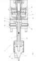
- Fig. 1 shows a sectional view of a heating device 1 for locally heating of an injection mold cavity wall (2) according to the invention.
- the invention comprises a base plate 3a / 3b, which is located between a heated stamp 5 and an actuator 4.
- the actuator 4 is located on top the base plate (in the figure on the right side), to perform a linear movement 27 ( Fig. 2 ).
- a bore which is at least par-tically threaded. The bore extends from the top to the bottom of the actuator, so that pin 7 located and fixed within the bore can be introduced from both sides.
- a heated stamp 5 is fixed. The pin translates the linear movement of the actuator to the heated stamp.
- the heated stamp is move in direction the injection mold cavity wall and brought into contact with the injection mold cavitiy to locally heat the injection mold cavity wall ( Fig. 7a ).
- the heated stamp 5 is located below the base plate and the actuator 5 is located on top of the base plate.
- the base plate comprises an opening 6 through which the pin 7 extends for transferring the linear movement from the actuator to the heated stamp.
- the pin is surrounded by a pin tube 32 which also serves as a anti rotation means. At distinct areas of the (top and or bottom) pin tube 32 flatted side walls are designed which are in contact with flatted areas of the heated stamp and the base plate 3a, which prevents the heated stamp to rotate.
- the bin tube is made of a less heat conductive material to reduce heat loss form the heated stamp. This part does not move relative to the base plate.
- the pin tube is fixed in the base plate by screws 20 and or by the base plate 3b.
- a slide offset of the screws to the grove takes care that the pin tube is pressed against the base plate. This could also be used to define the angle of the heated stamp if rotation would be adjustable (no anti rotation flats on pin tube and base plate).
- a position nut 9 and a lock nut 10 are located to fix the requested position of the heated stamp and set a stroke limitation.
- the nuts are screwed into t threaded bore.
- the position nut embraces a pin head 18 and holds the pin which enables the actuator to drive the pin in both directions through an opening 6 in the base plate.
- the lock nut have the function of counter screws.
- a temperature sensor 19 extends from the base plate to measure the temperature on the surface of the injection mold cavity in vicinity of the contact area of the heated stamp.
- a position switch 13 On the upper surface 12 of the actuator a position switch 13 is located. In this area anti rotate secured switching cam held by hollow screw is located.
- the hollow structure allows access to the position nut and the lock nut below.
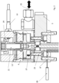
- Fig. 2 shows a sectional view of the upper part of the invention with the actuator 4 on top of the base plate 3.
- the base plate and the actuator 4 are held together with screws 23, which extend from the bottom of the base plate through the base plate into the bottom surface of the actuator 4, so that both units are clamped together.
- the base plate also comprises fluid inlet/outlet 25 for fluid (air/hydraulic) to drive the actuator and / or for cooling purposes to cool the actuator to protect the actuator from the heat of the surrounding components.
- the inlet/oulet 25 can be located at different positions on top at the side or at the bottom of the base plate. In some embodiments the fluid inlet/outlets are located directly at the housing of the actuator.
- set pin(s) 8 are located to define and keep the distance between the injection mold cavity 2 and the invention.
- the set pins are located in bores preferably blind bores and are pressed into the bores.
- the outlet of the temperature sensor extends below the base plate to a side of the base plate.
- the arrow 27 shows the linear movement directions of the actuator.
- the position switch 13 On the upper surface 12 of the actuator the position switch 13 is located being triggered by a switch cam 24 which is driven by the linear movements of the actuator.
- the switch cam 24 is fixed to upper end of the threaded bore by a hollow screw 21 which extends into the threaded bore and is located above the lock nut and position nut.
- FIG. 3 shows a sectional view of the lower part of the invention.
- the temperature sensor 19 extends through a bo-re/passage 15 in the heated stamp 5.
- a gap 30 in the bore passage 15 prevents an overheating of the temperature sensor 19 and its cables.
- a protection pipe 31 surrounds the temperature sensor and its cables as a heat protection.
- the heated stamp has at its outer surface a heating 22 which is wrapped around a core of the heated stamp.
- the core has notches surrounding the core in the shape of a coil.
- the pin is moving up and down in a pin tube 32 which has at its end anti rotation means 16 designed as flat surfaces that prevent a rotation of the heated stamp.
- Fig. 4a shows a sided view of the heated stamp with the rotatable heating 33 and the outlet 34 of the heating.
- Fig. 4b shows a sectional view along the cut E-E of Fig 4a.
- Fig. 4b shows that the heater/heating can be turned to change the location of an outlet 34 , so that the cabling can be adapted to the location when fixed to the hot runner system.
- Fig. 5a-5c show the heater 33 and the outlet 34 in a sectional view. Also, it is disclosed that heated stamp is fixed to the pin by screws 14, which are screwed into threaded bores extending into a center bore in which the pin is located.
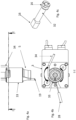
- Fig. 6a shows a top view onto the heating device attached by a bracket 37 to the hot runner system 35. Due to the slotted bracket a flexible mount to the hot runner system is possible.
- the bracket is L-shape and is on one end connected to the manifold 36 of the hot runner system 35 and on the other end to the heating device.
- the bracket is attached to the base plate of the heating device. Both the heating device and the
- brackets are possible like a straight bracket, a rounded bracket etc.
- Supports for adaptation on bracket or holding means take care for flexible mounting on hot runner system.
- Sensor cables and actuator powering (oil, air or electric) is integrated in the same cable channel and/or connector plate like the sensor and/or actuator powering of the hot runner system.
- Fig. 6b shows a side view of Fig. 6a , where the slotted bracket can be seen.
- the bracket 37 is screwed to the manifold and the base plate. Each of them has threaded bores in which screws extend.
- the holding means comprise screws the bracket 37 and bushings between the bracket and the screws.
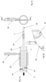
- Fig. 7a shows that the heated stamp 5 is in contact with the injection mold cavity 2 and is heating the contact area to improve the quality of the injected plastic 39.
- Fig. 7b shows that the heated stamp 5 is removed from the injection mold cavity 2 so that the plastic can cure.
- Fig. 8 shows a sectional view through a device according Fig. 9 .
- a cooling 40 is located, to prevent heat to damage the actuator.
- the base plate 3 is located directly on the manifold 36.
- the heating 22 can be rotated around the heated stamp 5 designed as a sleeve.
Landscapes
- Engineering & Computer Science (AREA)
- Manufacturing & Machinery (AREA)
- Mechanical Engineering (AREA)
- Physics & Mathematics (AREA)
- Thermal Sciences (AREA)
- Moulds For Moulding Plastics Or The Like (AREA)
- Injection Moulding Of Plastics Or The Like (AREA)
Claims (4)
- Heißkanalsystem, das Haltemittel umfasst, die eine Heizvorrichtung zum lokalen Erwärmen einer Spritzgussform-Hohlraumwand (2) physisch halten, wobei die Haltemittel so konfiguriert sind, dass das Hauptgewicht der Heizvorrichtung von dem Heißkanalsystem getragen wird, wobei die Heizvorrichtung einen Aktuator umfasst, um eine lineare Bewegung auszuführen; einen beheizten Stempel (5), der mit dem Aktuator (4) verbunden ist und von dem Aktuator angetrieben wird, um eine lineare Bewegung in Richtung auf die und von der Spritzgussform-Hohlraumwand (2) auszuführen, dadurch gekennzeichnet, dass der Heizstempel von denselben Medien oder derselben Energie angetrieben wird, die für das Heißkanalsystem bereitgestellt werden.
- Der Heißkanalsystem nach Anspruch 1, wobei sich die Heizvorrichtung dieselben Sensorkabel und/oder Kabelkanäle und/oder Adapterplatten und/oder Anschlussplatten teilt, an denen die Anschlüsse für das Heißkanalsystem enden.
- Der Heißkanalsystem nach einem der Ansprüche 1 und 2, wobei die Heizvorrichtung eine Grundplatte umfasst, an der auf einer Seite das Stellglied befestigt ist, und wobei der beheizte Stempel (5) auf der anderen Seite der Grundplatte angeordnet ist und die Grundplatte eine Öffnung (6) umfasst, durch die der beheizte Stempel (5) und das Stellglied verbunden sind, wobei die Grundplatte mit einem Verteiler verbunden ist oder in den Verteiler integriert ist, der ein Teil des Verteilers ist.
- Der Heißkanalsystem nach einem der vorhergehenden Ansprüche 1 bis 3, wobei die Medien Flüssigkeiten, hydraulische oder pneumatische Fluide und/oder Elektrizität sind.
Priority Applications (1)
| Application Number | Priority Date | Filing Date | Title |
|---|---|---|---|
| EP23189990.7A EP4257331B1 (de) | 2021-07-07 | 2021-07-07 | Heizvorrichtung |
Applications Claiming Priority (2)
| Application Number | Priority Date | Filing Date | Title |
|---|---|---|---|
| EP23189990.7A EP4257331B1 (de) | 2021-07-07 | 2021-07-07 | Heizvorrichtung |
| EP21184211.7A EP4116061B1 (de) | 2021-07-07 | 2021-07-07 | Heizvorrichtung |
Related Parent Applications (2)
| Application Number | Title | Priority Date | Filing Date |
|---|---|---|---|
| EP21184211.7A Division EP4116061B1 (de) | 2021-07-07 | 2021-07-07 | Heizvorrichtung |
| EP21184211.7A Division-Into EP4116061B1 (de) | 2021-07-07 | 2021-07-07 | Heizvorrichtung |
Publications (4)
| Publication Number | Publication Date |
|---|---|
| EP4257331A2 EP4257331A2 (de) | 2023-10-11 |
| EP4257331A3 EP4257331A3 (de) | 2024-01-03 |
| EP4257331B1 true EP4257331B1 (de) | 2025-03-26 |
| EP4257331C0 EP4257331C0 (de) | 2025-03-26 |
Family
ID=76829420
Family Applications (2)
| Application Number | Title | Priority Date | Filing Date |
|---|---|---|---|
| EP21184211.7A Active EP4116061B1 (de) | 2021-07-07 | 2021-07-07 | Heizvorrichtung |
| EP23189990.7A Active EP4257331B1 (de) | 2021-07-07 | 2021-07-07 | Heizvorrichtung |
Family Applications Before (1)
| Application Number | Title | Priority Date | Filing Date |
|---|---|---|---|
| EP21184211.7A Active EP4116061B1 (de) | 2021-07-07 | 2021-07-07 | Heizvorrichtung |
Country Status (12)
| Country | Link |
|---|---|
| US (2) | US12390970B2 (de) |
| EP (2) | EP4116061B1 (de) |
| JP (1) | JP2024524428A (de) |
| KR (1) | KR20240028991A (de) |
| CN (1) | CN117651636A (de) |
| CA (1) | CA3225550A1 (de) |
| ES (1) | ES2993215T3 (de) |
| HU (1) | HUE068611T2 (de) |
| IL (1) | IL309692A (de) |
| MX (1) | MX2024000254A (de) |
| PL (1) | PL4116061T3 (de) |
| WO (1) | WO2023282943A1 (de) |
Family Cites Families (15)
| Publication number | Priority date | Publication date | Assignee | Title |
|---|---|---|---|---|
| US3911251A (en) | 1973-11-05 | 1975-10-07 | Charles L Day | Heating device for molding |
| CA1261569A (en) | 1987-07-15 | 1989-09-26 | Jobst U. Gellert | Injection molding multiple nozzle valve gating system |
| JPH0753395B2 (ja) * | 1990-09-12 | 1995-06-07 | 日本電装株式会社 | ホットランナ式射出成形装置 |
| CA2041850A1 (en) | 1991-05-06 | 1992-11-07 | Jobst Ulrich Gellert | Injection molding apparatus with heated valve member |
| US5106291A (en) * | 1991-05-22 | 1992-04-21 | Gellert Jobst U | Injection molding apparatus with heated valve member |
| US6294122B1 (en) * | 1998-06-26 | 2001-09-25 | Synventive Molding Solutions, Inc. | Electric actuator for a melt flow control pin |
| JP3814169B2 (ja) * | 2001-07-23 | 2006-08-23 | 株式会社小糸製作所 | 車輌用灯具のレンズの成形方法及び成形金型 |
| JP3888580B2 (ja) | 2002-05-30 | 2007-03-07 | 富士電機デバイステクノロジー株式会社 | 記録媒体用基板を製造する方法および射出成形装置 |
| DE60316444T2 (de) * | 2002-07-30 | 2008-01-10 | Mold-Masters Limited, Georgetown | Ventilnadelführungs- und -ausrichtungssystem für einen heisskanal in einer spritzgiessvorrichtung |
| US20040166189A1 (en) * | 2003-02-25 | 2004-08-26 | Mold-Masters Limited | Injection molding system with flow control |
| JP2007223168A (ja) | 2006-02-23 | 2007-09-06 | Shibata Gosei:Kk | 成形金型装置 |
| JP4567011B2 (ja) * | 2007-02-15 | 2010-10-20 | 株式会社日本製鋼所 | 射出成形方法および射出成形装置 |
| JP2009226778A (ja) | 2008-03-24 | 2009-10-08 | Shibata Gosei:Kk | 金型用面状カーボンヒータ及びその製造方法ならびに金型装置 |
| FR2991902A1 (fr) | 2012-06-18 | 2013-12-20 | Roctool | Procede et dispositif pour le prechauffage d'un moule notamment de moulage par injection |
| DE102014114772A1 (de) | 2014-10-13 | 2016-04-14 | Hotset Heizpatronen Und Zubehör Gmbh | Vorrichtung zum Spritzgießen von Spritzgießteilen aus zum Spritzgießen geeignetem Werkstoff |
-
2021
- 2021-07-07 ES ES21184211T patent/ES2993215T3/es active Active
- 2021-07-07 HU HUE21184211A patent/HUE068611T2/hu unknown
- 2021-07-07 EP EP21184211.7A patent/EP4116061B1/de active Active
- 2021-07-07 PL PL21184211.7T patent/PL4116061T3/pl unknown
- 2021-07-07 EP EP23189990.7A patent/EP4257331B1/de active Active
-
2022
- 2022-02-07 US US17/650,107 patent/US12390970B2/en active Active
- 2022-03-31 IL IL309692A patent/IL309692A/en unknown
- 2022-03-31 CN CN202280048213.4A patent/CN117651636A/zh active Pending
- 2022-03-31 MX MX2024000254A patent/MX2024000254A/es unknown
- 2022-03-31 KR KR1020237043797A patent/KR20240028991A/ko active Pending
- 2022-03-31 CA CA3225550A patent/CA3225550A1/en active Pending
- 2022-03-31 WO PCT/US2022/022834 patent/WO2023282943A1/en not_active Ceased
- 2022-03-31 JP JP2023580777A patent/JP2024524428A/ja active Pending
-
2025
- 2025-07-28 US US19/282,742 patent/US20250353230A1/en active Pending
Also Published As
| Publication number | Publication date |
|---|---|
| PL4116061T3 (pl) | 2025-01-20 |
| US20250353230A1 (en) | 2025-11-20 |
| US12390970B2 (en) | 2025-08-19 |
| WO2023282943A1 (en) | 2023-01-12 |
| EP4116061A1 (de) | 2023-01-11 |
| EP4257331A3 (de) | 2024-01-03 |
| EP4257331C0 (de) | 2025-03-26 |
| EP4116061C0 (de) | 2024-09-04 |
| ES2993215T3 (en) | 2024-12-26 |
| MX2024000254A (es) | 2024-04-18 |
| EP4116061B1 (de) | 2024-09-04 |
| HUE068611T2 (hu) | 2025-01-28 |
| IL309692A (en) | 2024-02-01 |
| CA3225550A1 (en) | 2023-01-12 |
| JP2024524428A (ja) | 2024-07-05 |
| KR20240028991A (ko) | 2024-03-05 |
| US20230010091A1 (en) | 2023-01-12 |
| CN117651636A (zh) | 2024-03-05 |
| EP4257331A2 (de) | 2023-10-11 |
Similar Documents
| Publication | Publication Date | Title |
|---|---|---|
| KR102178404B1 (ko) | 플라스틱 재료의 사출성형 장치의 몰드의 고정 플레이트 | |
| EP1884336B1 (de) | Klemmvorrichtung die auf einer Aufspannplatte einer Spritzgiessmaschine montiert ist | |
| US9802348B2 (en) | Heater and thermocouple assembly | |
| RU2254993C2 (ru) | Узел цилиндра подготовки материала | |
| JP5425581B2 (ja) | 射出成形機 | |
| EP4257331B1 (de) | Heizvorrichtung | |
| EP1488905B1 (de) | Heisskanalverteiler mit mehrachsig justierbaren Verteilerblöcken und Düsen | |
| US5334006A (en) | Hot sprue bushing with interchangeable tip having multiple edge gates | |
| JPH0753395B2 (ja) | ホットランナ式射出成形装置 | |
| RU2268807C2 (ru) | Инжекционный узел | |
| CN108454011B (zh) | 用于注射模制装置的热流道注射喷嘴和致动器 | |
| JPH1058498A (ja) | 射出成形装置 | |
| JPH04308718A (ja) | 射出成形装置 | |
| CA2248469C (en) | Mould device with adjustable walls | |
| US20100272851A1 (en) | Injection molding nozzle | |
| JPH05263125A (ja) | 全自動高周波焼入れ装置 | |
| JP2020055198A (ja) | 射出成型機 | |
| CN117020537B (zh) | 一种钢棒材焊接装置 | |
| JP4782720B2 (ja) | プリプラ式射出成形機 | |
| JPH11156907A (ja) | 微小構造体の成形方法および成形装置 | |
| TWI904161B (zh) | 用於側向澆注之熱澆道噴嘴 | |
| CA2835600A1 (en) | Selective positioning of nozzle tip relative to mold-side of runner system | |
| CN121535159A (zh) | 一种热流道加热器的加工装置与工艺 | |
| JPH0361519A (ja) | 射出成形機の金型装着装置 | |
| JP2002320893A (ja) | 塗布ガン加温装置 |
Legal Events
| Date | Code | Title | Description |
|---|---|---|---|
| PUAI | Public reference made under article 153(3) epc to a published international application that has entered the european phase |
Free format text: ORIGINAL CODE: 0009012 |
|
| STAA | Information on the status of an ep patent application or granted ep patent |
Free format text: STATUS: THE APPLICATION HAS BEEN PUBLISHED |
|
| AC | Divisional application: reference to earlier application |
Ref document number: 4116061 Country of ref document: EP Kind code of ref document: P |
|
| AK | Designated contracting states |
Kind code of ref document: A2 Designated state(s): AL AT BE BG CH CY CZ DE DK EE ES FI FR GB GR HR HU IE IS IT LI LT LU LV MC MK MT NL NO PL PT RO RS SE SI SK SM TR |
|
| REG | Reference to a national code |
Ref legal event code: R079 Free format text: PREVIOUS MAIN CLASS: B29C0045270000 Ipc: B29C0045730000 Ref country code: DE Ref legal event code: R079 Ref document number: 602021028342 Country of ref document: DE Free format text: PREVIOUS MAIN CLASS: B29C0045270000 Ipc: B29C0045730000 |
|
| PUAL | Search report despatched |
Free format text: ORIGINAL CODE: 0009013 |
|
| AK | Designated contracting states |
Kind code of ref document: A3 Designated state(s): AL AT BE BG CH CY CZ DE DK EE ES FI FR GB GR HR HU IE IS IT LI LT LU LV MC MK MT NL NO PL PT RO RS SE SI SK SM TR |
|
| RIC1 | Information provided on ipc code assigned before grant |
Ipc: B29C 45/27 20060101ALI20231128BHEP Ipc: B29C 45/00 20060101ALI20231128BHEP Ipc: B29C 45/73 20060101AFI20231128BHEP |
|
| STAA | Information on the status of an ep patent application or granted ep patent |
Free format text: STATUS: REQUEST FOR EXAMINATION WAS MADE |
|
| RAP3 | Party data changed (applicant data changed or rights of an application transferred) |
Owner name: INCOE CORPORATION |
|
| 17P | Request for examination filed |
Effective date: 20240220 |
|
| RBV | Designated contracting states (corrected) |
Designated state(s): AL AT BE BG CH CY CZ DE DK EE ES FI FR GB GR HR HU IE IS IT LI LT LU LV MC MK MT NL NO PL PT RO RS SE SI SK SM TR |
|
| GRAP | Despatch of communication of intention to grant a patent |
Free format text: ORIGINAL CODE: EPIDOSNIGR1 |
|
| STAA | Information on the status of an ep patent application or granted ep patent |
Free format text: STATUS: GRANT OF PATENT IS INTENDED |
|
| INTG | Intention to grant announced |
Effective date: 20241025 |
|
| GRAS | Grant fee paid |
Free format text: ORIGINAL CODE: EPIDOSNIGR3 |
|
| GRAA | (expected) grant |
Free format text: ORIGINAL CODE: 0009210 |
|
| STAA | Information on the status of an ep patent application or granted ep patent |
Free format text: STATUS: THE PATENT HAS BEEN GRANTED |
|
| AC | Divisional application: reference to earlier application |
Ref document number: 4116061 Country of ref document: EP Kind code of ref document: P |
|
| AK | Designated contracting states |
Kind code of ref document: B1 Designated state(s): AL AT BE BG CH CY CZ DE DK EE ES FI FR GB GR HR HU IE IS IT LI LT LU LV MC MK MT NL NO PL PT RO RS SE SI SK SM TR |
|
| REG | Reference to a national code |
Ref country code: GB Ref legal event code: FG4D |
|
| REG | Reference to a national code |
Ref country code: CH Ref legal event code: EP |
|
| REG | Reference to a national code |
Ref country code: DE Ref legal event code: R096 Ref document number: 602021028342 Country of ref document: DE |
|
| REG | Reference to a national code |
Ref country code: IE Ref legal event code: FG4D |
|
| U01 | Request for unitary effect filed |
Effective date: 20250326 |
|
| U07 | Unitary effect registered |
Designated state(s): AT BE BG DE DK EE FI FR IT LT LU LV MT NL PT RO SE SI Effective date: 20250401 |
|
| PG25 | Lapsed in a contracting state [announced via postgrant information from national office to epo] |
Ref country code: RS Free format text: LAPSE BECAUSE OF FAILURE TO SUBMIT A TRANSLATION OF THE DESCRIPTION OR TO PAY THE FEE WITHIN THE PRESCRIBED TIME-LIMIT Effective date: 20250626 |
|
| PG25 | Lapsed in a contracting state [announced via postgrant information from national office to epo] |
Ref country code: NO Free format text: LAPSE BECAUSE OF FAILURE TO SUBMIT A TRANSLATION OF THE DESCRIPTION OR TO PAY THE FEE WITHIN THE PRESCRIBED TIME-LIMIT Effective date: 20250626 |
|
| PG25 | Lapsed in a contracting state [announced via postgrant information from national office to epo] |
Ref country code: HR Free format text: LAPSE BECAUSE OF FAILURE TO SUBMIT A TRANSLATION OF THE DESCRIPTION OR TO PAY THE FEE WITHIN THE PRESCRIBED TIME-LIMIT Effective date: 20250326 |
|
| PG25 | Lapsed in a contracting state [announced via postgrant information from national office to epo] |
Ref country code: GR Free format text: LAPSE BECAUSE OF FAILURE TO SUBMIT A TRANSLATION OF THE DESCRIPTION OR TO PAY THE FEE WITHIN THE PRESCRIBED TIME-LIMIT Effective date: 20250627 |
|
| U20 | Renewal fee for the european patent with unitary effect paid |
Year of fee payment: 5 Effective date: 20250731 |
|
| PG25 | Lapsed in a contracting state [announced via postgrant information from national office to epo] |
Ref country code: SM Free format text: LAPSE BECAUSE OF FAILURE TO SUBMIT A TRANSLATION OF THE DESCRIPTION OR TO PAY THE FEE WITHIN THE PRESCRIBED TIME-LIMIT Effective date: 20250326 |
|
| PG25 | Lapsed in a contracting state [announced via postgrant information from national office to epo] |
Ref country code: ES Free format text: LAPSE BECAUSE OF FAILURE TO SUBMIT A TRANSLATION OF THE DESCRIPTION OR TO PAY THE FEE WITHIN THE PRESCRIBED TIME-LIMIT Effective date: 20250326 |
|
| PG25 | Lapsed in a contracting state [announced via postgrant information from national office to epo] |
Ref country code: PL Free format text: LAPSE BECAUSE OF FAILURE TO SUBMIT A TRANSLATION OF THE DESCRIPTION OR TO PAY THE FEE WITHIN THE PRESCRIBED TIME-LIMIT Effective date: 20250326 |
|
| PG25 | Lapsed in a contracting state [announced via postgrant information from national office to epo] |
Ref country code: SK Free format text: LAPSE BECAUSE OF FAILURE TO SUBMIT A TRANSLATION OF THE DESCRIPTION OR TO PAY THE FEE WITHIN THE PRESCRIBED TIME-LIMIT Effective date: 20250326 |
|
| PG25 | Lapsed in a contracting state [announced via postgrant information from national office to epo] |
Ref country code: IS Free format text: LAPSE BECAUSE OF FAILURE TO SUBMIT A TRANSLATION OF THE DESCRIPTION OR TO PAY THE FEE WITHIN THE PRESCRIBED TIME-LIMIT Effective date: 20250726 |
|
| PLBI | Opposition filed |
Free format text: ORIGINAL CODE: 0009260 |
|
| REG | Reference to a national code |
Ref country code: CH Ref legal event code: L10 Free format text: ST27 STATUS EVENT CODE: U-0-0-L10-L00 (AS PROVIDED BY THE NATIONAL OFFICE) Effective date: 20260114 |
|
| PLAX | Notice of opposition and request to file observation + time limit sent |
Free format text: ORIGINAL CODE: EPIDOSNOBS2 |
|
| PG25 | Lapsed in a contracting state [announced via postgrant information from national office to epo] |
Ref country code: CZ Free format text: LAPSE BECAUSE OF FAILURE TO SUBMIT A TRANSLATION OF THE DESCRIPTION OR TO PAY THE FEE WITHIN THE PRESCRIBED TIME-LIMIT Effective date: 20250326 |
|
| 26 | Opposition filed |
Opponent name: INGLASS S.P.A. Effective date: 20251222 |
|
| REG | Reference to a national code |
Ref country code: CH Ref legal event code: H13 Free format text: ST27 STATUS EVENT CODE: U-0-0-H10-H13 (AS PROVIDED BY THE NATIONAL OFFICE) Effective date: 20260224 |