EP4254751A1 - Verfahren und vorrichtung zur modulation digitaler signale, steuerungsverfahren für schaltnetzteil und schaltnetzteil - Google Patents
Verfahren und vorrichtung zur modulation digitaler signale, steuerungsverfahren für schaltnetzteil und schaltnetzteil Download PDFInfo
- Publication number
- EP4254751A1 EP4254751A1 EP20967547.9A EP20967547A EP4254751A1 EP 4254751 A1 EP4254751 A1 EP 4254751A1 EP 20967547 A EP20967547 A EP 20967547A EP 4254751 A1 EP4254751 A1 EP 4254751A1
- Authority
- EP
- European Patent Office
- Prior art keywords
- value
- modulation
- comparator
- counter
- duty cycle
- Prior art date
- Legal status (The legal status is an assumption and is not a legal conclusion. Google has not performed a legal analysis and makes no representation as to the accuracy of the status listed.)
- Pending
Links
Images



Classifications
-
- G—PHYSICS
- G05—CONTROLLING; REGULATING
- G05B—CONTROL OR REGULATING SYSTEMS IN GENERAL; FUNCTIONAL ELEMENTS OF SUCH SYSTEMS; MONITORING OR TESTING ARRANGEMENTS FOR SUCH SYSTEMS OR ELEMENTS
- G05B19/00—Program-control systems
- G05B19/02—Program-control systems electric
- G05B19/04—Program control other than numerical control, i.e. in sequence controllers or logic controllers
- G05B19/042—Program control other than numerical control, i.e. in sequence controllers or logic controllers using digital processors
- G05B19/0423—Input/output
-
- H—ELECTRICITY
- H02—GENERATION; CONVERSION OR DISTRIBUTION OF ELECTRIC POWER
- H02M—APPARATUS FOR CONVERSION BETWEEN AC AND AC, BETWEEN AC AND DC, OR BETWEEN DC AND DC, AND FOR USE WITH MAINS OR SIMILAR POWER SUPPLY SYSTEMS; CONVERSION OF DC OR AC INPUT POWER INTO SURGE OUTPUT POWER; CONTROL OR REGULATION THEREOF
- H02M1/00—Details of apparatus for conversion
- H02M1/44—Circuits or arrangements for compensating for electromagnetic interference in converters or inverters
-
- H—ELECTRICITY
- H02—GENERATION; CONVERSION OR DISTRIBUTION OF ELECTRIC POWER
- H02M—APPARATUS FOR CONVERSION BETWEEN AC AND AC, BETWEEN AC AND DC, OR BETWEEN DC AND DC, AND FOR USE WITH MAINS OR SIMILAR POWER SUPPLY SYSTEMS; CONVERSION OF DC OR AC INPUT POWER INTO SURGE OUTPUT POWER; CONTROL OR REGULATION THEREOF
- H02M3/00—Conversion of DC power input into DC power output
- H02M3/22—Conversion of DC power input into DC power output with intermediate conversion into AC
- H02M3/24—Conversion of DC power input into DC power output with intermediate conversion into AC by static converters
- H02M3/28—Conversion of DC power input into DC power output with intermediate conversion into AC by static converters using discharge tubes with control electrode or semiconductor devices with control electrode to produce the intermediate AC
- H02M3/325—Conversion of DC power input into DC power output with intermediate conversion into AC by static converters using discharge tubes with control electrode or semiconductor devices with control electrode to produce the intermediate AC using devices of a triode or a transistor type requiring continuous application of a control signal
- H02M3/335—Conversion of DC power input into DC power output with intermediate conversion into AC by static converters using discharge tubes with control electrode or semiconductor devices with control electrode to produce the intermediate AC using devices of a triode or a transistor type requiring continuous application of a control signal using semiconductor devices only
- H02M3/33507—Conversion of DC power input into DC power output with intermediate conversion into AC by static converters using discharge tubes with control electrode or semiconductor devices with control electrode to produce the intermediate AC using devices of a triode or a transistor type requiring continuous application of a control signal using semiconductor devices only with automatic control of the output voltage or current, e.g. flyback converters
- H02M3/33515—Conversion of DC power input into DC power output with intermediate conversion into AC by static converters using discharge tubes with control electrode or semiconductor devices with control electrode to produce the intermediate AC using devices of a triode or a transistor type requiring continuous application of a control signal using semiconductor devices only with automatic control of the output voltage or current, e.g. flyback converters with digital control
-
- H—ELECTRICITY
- H02—GENERATION; CONVERSION OR DISTRIBUTION OF ELECTRIC POWER
- H02M—APPARATUS FOR CONVERSION BETWEEN AC AND AC, BETWEEN AC AND DC, OR BETWEEN DC AND DC, AND FOR USE WITH MAINS OR SIMILAR POWER SUPPLY SYSTEMS; CONVERSION OF DC OR AC INPUT POWER INTO SURGE OUTPUT POWER; CONTROL OR REGULATION THEREOF
- H02M3/00—Conversion of DC power input into DC power output
- H02M3/22—Conversion of DC power input into DC power output with intermediate conversion into AC
- H02M3/24—Conversion of DC power input into DC power output with intermediate conversion into AC by static converters
- H02M3/28—Conversion of DC power input into DC power output with intermediate conversion into AC by static converters using discharge tubes with control electrode or semiconductor devices with control electrode to produce the intermediate AC
- H02M3/325—Conversion of DC power input into DC power output with intermediate conversion into AC by static converters using discharge tubes with control electrode or semiconductor devices with control electrode to produce the intermediate AC using devices of a triode or a transistor type requiring continuous application of a control signal
- H02M3/335—Conversion of DC power input into DC power output with intermediate conversion into AC by static converters using discharge tubes with control electrode or semiconductor devices with control electrode to produce the intermediate AC using devices of a triode or a transistor type requiring continuous application of a control signal using semiconductor devices only
- H02M3/33569—Conversion of DC power input into DC power output with intermediate conversion into AC by static converters using discharge tubes with control electrode or semiconductor devices with control electrode to produce the intermediate AC using devices of a triode or a transistor type requiring continuous application of a control signal using semiconductor devices only having several active switching elements
- H02M3/33576—Conversion of DC power input into DC power output with intermediate conversion into AC by static converters using discharge tubes with control electrode or semiconductor devices with control electrode to produce the intermediate AC using devices of a triode or a transistor type requiring continuous application of a control signal using semiconductor devices only having several active switching elements having at least one active switching element at the secondary side of an isolation transformer
- H02M3/33584—Bidirectional converters
-
- H—ELECTRICITY
- H03—ELECTRONIC CIRCUITRY
- H03K—PULSE TECHNIQUE
- H03K21/00—Details of pulse counters or frequency dividers
- H03K21/38—Starting, stopping or resetting the counter
-
- H—ELECTRICITY
- H03—ELECTRONIC CIRCUITRY
- H03K—PULSE TECHNIQUE
- H03K3/00—Circuits for generating electric pulses; Monostable, bistable or multistable circuits
- H03K3/01—Details
- H03K3/017—Adjustment of width or dutycycle of pulses
-
- H—ELECTRICITY
- H03—ELECTRONIC CIRCUITRY
- H03K—PULSE TECHNIQUE
- H03K7/00—Modulating pulses with a continuously-variable modulating signal
- H03K7/08—Duration or width modulation ; Duty cycle modulation
-
- G—PHYSICS
- G05—CONTROLLING; REGULATING
- G05B—CONTROL OR REGULATING SYSTEMS IN GENERAL; FUNCTIONAL ELEMENTS OF SUCH SYSTEMS; MONITORING OR TESTING ARRANGEMENTS FOR SUCH SYSTEMS OR ELEMENTS
- G05B2219/00—Program-control systems
- G05B2219/20—Pc systems
- G05B2219/25—Pc structure of the system
- G05B2219/25257—Microcontroller
-
- G—PHYSICS
- G05—CONTROLLING; REGULATING
- G05B—CONTROL OR REGULATING SYSTEMS IN GENERAL; FUNCTIONAL ELEMENTS OF SUCH SYSTEMS; MONITORING OR TESTING ARRANGEMENTS FOR SUCH SYSTEMS OR ELEMENTS
- G05B2219/00—Program-control systems
- G05B2219/30—Nc systems
- G05B2219/42—Servomotor, servo controller kind till VSS
- G05B2219/42237—Pwm pulse width modulation, pulse to position modulation ppm
-
- Y—GENERAL TAGGING OF NEW TECHNOLOGICAL DEVELOPMENTS; GENERAL TAGGING OF CROSS-SECTIONAL TECHNOLOGIES SPANNING OVER SEVERAL SECTIONS OF THE IPC; TECHNICAL SUBJECTS COVERED BY FORMER USPC CROSS-REFERENCE ART COLLECTIONS [XRACs] AND DIGESTS
- Y02—TECHNOLOGIES OR APPLICATIONS FOR MITIGATION OR ADAPTATION AGAINST CLIMATE CHANGE
- Y02B—CLIMATE CHANGE MITIGATION TECHNOLOGIES RELATED TO BUILDINGS, e.g. HOUSING, HOUSE APPLIANCES OR RELATED END-USER APPLICATIONS
- Y02B70/00—Technologies for an efficient end-user side electric power management and consumption
- Y02B70/10—Technologies improving the efficiency by using switched-mode power supplies [SMPS], i.e. efficient power electronics conversion e.g. power factor correction or reduction of losses in power supplies or efficient standby modes
Definitions
- This application relates to the field of digital coding technologies, and in particular, to a digital signal modulation method and apparatus, a power converter control method, and a power converter.
- SiC silicon carbide
- GaN gallium nitride
- SiC power module or GaN power module has a relatively good frequency switching characteristic, and can implement a switching frequency of hundreds of KHz (kilohertz), where the switching frequency of the GaN power module may even be higher.
- KHz KHz
- a higher switching frequency can significantly reduce the size of the inductor-capacitor-transformer in the power converter, which is the key to improve the power density of the entire system.
- the power converter is applicable for different application scenarios.
- an analog chip may be used to generate an analog PWM signal to control working of the power converter
- a programmable controller may be used to generate a digital PWM signal to control working of the power converter.
- Analog PWM signals are continuously changing signals, and once the analog PWM signals are calibrated, there is no precision problem.
- Digital PWM signals simulate continuously changing signals by using discrete values. A clock of a common digital PWM generator does not exceed 200 MHz. Therefore, when a switching frequency is relatively high, the discrete value is excessively high, which affects precision of the digital PWM signal.
- a digital PWM generator generates a corresponding PWM signal by setting a value of a counter (Counter) and a value of a comparator (Comparator), and a duty cycle of the PWM signal may be obtained based on a ratio of the value of the comparator to the value of the counter.
- Modulation modes of the PWM signal can be classified into pulse width modulation (Pulse width modulation, PWM) and pulse frequency modulation (Pulse frequency modulation, PFM).
- pulse width modulation pulse width may be changed by modifying the value of the comparator, so as to change the duty cycle.
- pulse frequency modulation In pulse frequency modulation, pulse frequency may be changed by modifying the value of the counter or modifying both the value of the counter and the value of the comparator, so as to change the duty cycle.
- pulse frequency modulation usually causes a pulse frequency jitter in a relatively wide range. A common power converter is unlikely to work in a very wide frequency range. Therefore, an actual adjustable duty cycle range of pulse frequency modulation is not large, and an application scope is relatively small, for example, pulse frequency modulation is generally used in an LLC resonant circuit.
- an existing microcontroller unit can configure PWM signal output to the dither mode, so that a value of the comparator jitters in a specific range, and precision of the average duty cycle is improved.
- the value of the counter of the PWM signal is 10.
- PWM signals with an average duty cycle of 4.25/10, 4.5/10, and 4.75/10 may be implemented.
- a maximum of 4-bit jitter can be configured for a microcontroller unit.
- a disadvantage of the dither mode is that time is required for exchange of precision.
- a jitter value Based on an exponential relationship between a jitter value and time, for example, if the jitter value is increased by 2 bits, it takes four periods to implement a duty cycle precision of 4.75/10; or if the jitter value is increased by 4 bits, it takes 16 periods to implement the duty cycle precision of 4.75/10.
- a 4-bit dither mode is adopted, which significantly reduces an output response speed.
- the dither mode further increases an output filtering difficulty, and a duty cycle of a PWM signal output in dither mode has a higher precision only than an average value, but the duty cycle precision of each cycle is still relatively low.
- the jitter of the duty cycle of the PWM signal may cause jitter of the output voltage and current, which may easily cause the switching frequency of a power converter to be lower than the frequency of ripple oscillations.
- a microcontroller unit with a higher frequency and performance may be selected.
- the frequency and performance of the microcontroller unit are only two to three times higher than those of a common microcontroller unit.
- the improvement is limited, but costs are increased significantly and the heat generated by the microcontroller unit is high.
- this application provides a digital signal modulation method and apparatus, a power converter control method, and a power converter. Pulse frequency modulation is performed on a PWM signal in each period without increasing hardware costs, so as to improve a duty cycle precision of the PWM signal in each period and output a PWM signal with a higher precision.
- a first aspect of this application provides a digital signal modulation method, including:
- a PWM technology is first used to generate periodic PWM signals based on a modulation value of a comparator and an initial value of a counter, then a PFM technology is used to perform pulse frequency modulation on a PWM signal in each period based on a calibration value, and a duty cycle precision of the PWM signal in each period is improved by using a method of properly changing a frequency, so that a PWM signal of higher precision is implemented without increasing hardware costs.
- the obtaining a modulation value of a comparator based on a target duty cycle and an initial value of a counter includes: obtaining an accurate value of the comparator through calculation based on the target duty cycle and the initial value of the counter, and rounding the accurate value of the comparator to obtain the modulation value of the comparator.
- the accurate value of the comparator may be obtained by performing a multiplication calculation based on the target duty cycle and the initial value of the counter.
- rounding is performed to obtain the modulation value of the comparator.
- the obtaining a calibration value based on the target duty cycle, the initial value of the counter, and the modulation value of the comparator includes: when the duty cycle of the PWM signal is less than 0.5, obtaining a first precision value through calculation based on a difference between the modulation value of the comparator and the accurate value of the comparator, the modulation value of the comparator, and the initial value of the counter, and rounding the first precision value to obtain a first calibration value.
- a corresponding calculation method is selected based on whether the duty cycle of the PWM signal is less than 0.5 to calculate a calibration value.
- the first precision value is obtained through calculation based on the difference between the modulation value of the comparator and the accurate value of the comparator, the modulation value of the comparator, and the initial value of the counter.
- the first precision value has a decimal place, rounding is performed to obtain the first calibration value, and the initial value of the counter is modulated by using the first calibration value, so as to implement frequency modulation on the generated PWM signal in each period, thereby further improving a duty cycle precision of the PWM signal in each period.
- the performing pulse frequency modulation on a PWM signal in each period in the periodic PWM signals based on the calibration value includes: modulating the initial value of the counter of the PWM signal in each period in the periodic PWM signals based on the first calibration value.
- pulse frequency modulation includes high-level fixed-length pulse frequency modulation and low-level fixed-length pulse frequency modulation.
- the high-level fixed-length pulse frequency modulation means that a high-level pulse width remains unchanged and only the initial value of the counter is modulated.
- the low-level fixed-length pulse frequency modulation means that a low-level pulse width remains unchanged and the modulation value of the comparator and the initial value of the counter need to be modulated at the same time.
- the high-level fixed-length pulse frequency modulation may be selected to modulate the initial value of the counter, thereby improving the duty cycle precision of a finally output PWM signal.
- the high-level fixed-length pulse frequency modulation is selected, that is, the initial value of the counter needs to be modulated based on the first calibration value.
- a modulation direction is the same as a rounding direction. If the accurate value of the comparator is rounded down, that is, the modulation value of the comparator is less than the accurate value of the comparator, to further improve the duty cycle precision value, subtraction modulation also needs to be performed on the initial value of the counter, where a modulation amount is the first calibration value obtained by calculation.
- the method further includes: when the duty cycle of the PWM signal is greater than or equal to 0.5, obtaining a second precision value through calculation based on the difference between the modulation value of the comparator and the accurate value of the comparator, a difference between the modulation value of the comparator and the initial value of the counter, and the initial value of the counter, and rounding the second precision value to obtain a second calibration value.
- the second precision value is obtained through calculation based on the difference between the modulation value of the comparator and the accurate value of the comparator, the difference between the modulation value of the comparator and the initial value of the counter, and the initial value of the counter.
- rounding is performed to obtain the second calibration value.
- the initial value of the counter and the modulation value of the comparator are modulated by using the second calibration value, so as to implement frequency modulation on the generated PWM signal in each period, thereby further improving the duty cycle precision of the PWM signal in each period.
- the performing pulse frequency modulation on a PWM signal in each period in the periodic PWM signals based on the calibration value includes: modulating the initial value of the counter and a modulation value of the comparator of the PWM signal in each period in the periodic PWM signals based on the second calibration value.
- pulse frequency modulation includes high-level fixed-length pulse frequency modulation and low-level fixed-length pulse frequency modulation.
- the high-level fixed-length pulse frequency modulation means that a high-level pulse width remains unchanged and only the initial value of the counter is modulated.
- the low-level fixed-length pulse frequency modulation means that a low-level pulse width remains unchanged and the modulation value of the comparator and the initial value of the counter need to be modulated at the same time.
- the low-level fixed-length pulse frequency modulation may be selected to modulate the modulation value of the comparator and the initial value of the counter, thereby improving the duty cycle precision of a finally output PWM signal.
- low-level fixed-length pulse frequency modulation is selected, that is, the modulation value of the comparator and the initial value of the counter need to be modulated based on the second calibration value.
- the modulation direction is opposite to the rounding direction, that is, when the accurate value of the comparator is rounded down, addition modulation is performed on the initial value of the counter and the modulation value of the comparator; and conversely, when the accurate value of the comparator is rounded up, subtraction modulation is performed on the initial value of the counter and the modulation value of the comparator, thereby improving the duty cycle precision of the PWM signal in each period.
- the rounding includes: performing the rounding by taking a closest integer value.
- a round-off method may be used to obtain a closest integer value, so as to obtain a PWM signal closest to the target duty cycle through modulation.
- a digital signal modulation apparatus including:
- the obtaining a modulation value of a comparator based on a target duty cycle and an initial value of a counter includes: obtaining an accurate value of the comparator through calculation based on the target duty cycle and the initial value of the counter, and rounding the accurate value of the comparator to obtain the modulation value of the comparator.
- the obtaining a calibration value based on the target duty cycle, the initial value of the counter, and the modulation value of the comparator includes: when the duty cycle of the PWM signal is less than 0.5, obtaining a first precision value through calculation based on a difference between the modulation value of the comparator and the accurate value of the comparator, the modulation value of the comparator, and the initial value of the counter, and rounding the first precision value to obtain a first calibration value.
- the performing pulse frequency modulation on a PWM signal in each period in the periodic PWM signals based on the calibration value includes: modulating the initial value of the counter of the PWM signal in each period in the periodic PWM signals based on the first calibration value.
- the method further includes: when the duty cycle of the PWM signal is greater than or equal to 0.5, obtaining a second precision value through calculation based on the difference between the modulation value of the comparator and the accurate value of the comparator, a difference between the modulation value of the comparator and the initial value of the counter, and the initial value of the counter, and rounding the second precision value to obtain a second calibration value.
- the performing pulse frequency modulation on a PWM signal in each period in the periodic PWM signals based on the calibration value includes: modulating the initial value of the counter and a modulation value of the comparator of the PWM signal in each period in the periodic PWM signals based on the second calibration value.
- the rounding includes: performing the rounding by taking a closest integer value.
- a third aspect of this application provides a power converter control method, including:
- a fourth aspect of this application provides a power converter, including: a switch circuit, where a PWM signal of the switch circuit is provided by the apparatus based on any one of the digital signal modulation apparatuses.
- a fifth aspect of this application provides a computing device, including:
- a sixth aspect of this application provides a computer-readable storage medium, where the computer-readable storage medium stores program instructions.
- the program instructions When executed by a computer, the computer is enabled to perform the method based on any one of the digital signal modulation methods or the power converter control method.
- a seventh aspect of this application provides a computer program product, including program instructions.
- the program instructions When the program instructions are executed by a computer, the computer is enabled to perform the method based on any one of the digital signal modulation methods or the power converter control method.
- first, second, third, and the like or similar terms such as a module A, a module B, and a module C are merely used to distinguish between similar objects, and do not represent a specific order of the objects. It may be understood that specific orders or sequences may be exchanged if permitted, so that embodiments of this application described herein can be implemented in an order other than an order illustrated or described herein.
- involved reference numerals such as S110 and S120 that indicate steps do not necessarily indicate that the steps are to be performed based on the order, and consecutive steps may be transposed if allowed, or may be performed simultaneously.
- One embodiment or “an embodiment” mentioned in this specification indicates that a particular feature, structure or property that is described with reference to the embodiment is included in at least one embodiment of this application. Therefore, the terms “in one embodiment” or “in an embodiment” that appear in this specification do not necessarily indicate a same embodiment, but may indicate a same embodiment. Further, in one or more embodiments, the particular features, structures, or properties can be combined in any proper manner, as will be clear from this disclosure to a person of ordinary skill in the art.
- PWM pulse width modulation
- PFM pulse frequency modulation
- PWM duty cycle indicates a ratio of high level in a pulse cycle.
- PWM resolution indicates a quantity of PWM duty cycle adjustable levels.
- Duty cycle dispersion indicates a variation of duty cycles of two adjacent periods during pulse width modulation or pulse frequency modulation. A smaller duty cycle dispersion indicates a higher duty cycle adjustment precision.
- duty cycle dispersions of pulse width modulation (PWM) and pulse frequency modulation (PFM) are compared and analyzed to compare the duty cycle adjustable precisions in the two modulation modes.
- a value of a counter (Counter) is set to n, and a value of a comparator (Compare) is set to k.
- polarity reversal is configured for a PWM signal output by a microcontroller unit.
- the value of the counter is configured to be less than or equal to the value of the comparator, a high-level PWM signal is output.
- the value of the counter is greater than the value of the comparator, a low-level PWM signal is output. Therefore, it may be learned that a duty cycle of the PWM signal is k/n.
- Pulse frequency modulation includes two modulation modes: high-level fixed-length modulation and low-level fixed-length modulation.
- the high-level fixed-length pulse frequency modulation may be selected to implement modulation with a higher duty cycle precision.
- k ⁇ n/2 that is, when the duty cycle is greater than or equal to 0.5
- the duty cycle dispersion in the low-level fixed-length pulse frequency modulation is smaller. That is, when the duty cycle is greater than or equal to 0.5, the low-level fixed-length pulse frequency modulation may be selected to implement modulation with a higher duty cycle precision.
- this embodiment of this application provides a digital signal modulation method.
- the pulse width modulation is first used to generate periodic PWM signals, and then the pulse frequency modulation is performed on a PWM signal in each period.
- This method can avoid a problem that a pulse frequency of an output PWM signal changes significantly, and can further greatly improve a duty cycle precision of the output PWM signal. The following describes in detail this application.
- the method includes the following steps.
- S401 Obtain a modulation value of a comparator based on a target duty cycle and an initial value of a counter.
- S402 Obtain a calibration value based on the target duty cycle, the initial value of the counter, and the modulation value of the comparator.
- S403 Generate periodic PWM signals based on the modulation value of the comparator and an initial value of a counter.
- S404 Perform pulse frequency modulation on a PWM signal in each period in the periodic PWM signals based on the calibration value.
- the target duty cycle is a most precise duty cycle for achieving a working output target.
- a target duty cycle required for accurately outputting the working voltage may be determined based on a working voltage and a rated voltage that need to be output by the power converter.
- the modulation value and the calibration value of the comparator that needs to reach the target duty cycle may be obtained through calculation based on the target duty cycle and the initial value of the counter of a digital PWM generator.
- the modulation value of the comparator refers to a value that needs to be set by the comparator
- the calibration value refers to a value required for addition modulation and subtraction modulation when pulse frequency modulation is performed on the PWM signal.
- the modulation value and the calibration value of the comparator are integer values that can be modulated on a premise that modulation precision is met.
- the calculation specifically includes: A precise comparator value is obtained through calculation based on the target duty cycle and the initial value of the counter.
- the precise comparator value is defined as an accurate value of the comparator. If the accurate value of the comparator is a value with a decimal place, the accurate value of the comparator needs to be rounded to obtain a modulation value of the comparator for pulse width modulation.
- a specific deviation exists between the ratio of the rounded modulation value of the comparator to the initial value of the counter and the target duty cycle, where the deviation is less than a duty cycle dispersion generated by one pulse width modulation.
- further calculation may be performed based on the accurate value of the comparator, the modulation value of the comparator, and the initial value of the counter to obtain a calibration value for pulse frequency modulation.
- a process of calculating the calibration value needs to refer to a value of a duty cycle of a PWM signal, and the calculation process is performed based on a principle of obtaining a maximum calibration value.
- the modulation value of the comparator is used as a denominator for calculation, and a first precision value is obtained through calculation based on a difference between the modulation value of the comparator and the accurate value of the comparator, the modulation value of the comparator, and the initial value of the counter. If the first precision value is a value with a decimal place, the first precision value needs to be rounded to obtain a first calibration value used for pulse frequency modulation.
- the duty cycle of the PWM signal is greater than or equal to 0.5, that is, when the modulation value of the comparator is greater than or equal to half of the initial value of the counter
- a difference between the initial value of the counter and the modulation value of the comparator is used as a denominator for calculation, and a second precision value is obtained through calculation based on the difference between the modulation value of the comparator and the accurate value of the comparator, the difference between the modulation value of the comparator and the initial value of the counter, and the initial value of the counter.
- the second precision value is a value with a decimal place, the second precision value needs to be rounded to obtain a second calibration value used for pulse frequency modulation.
- the accurate value of the comparator, an integer value closest to the first precision value, and an integer value closest to the second precision value may be respectively obtained by using a round-off method, so as to implement more accurate pulse width modulation and pulse frequency modulation.
- Pulse width modulation and pulse frequency modulation may be performed based on the modulation value of the comparator, the first calibration value, and second calibration value that are obtained through calculation. Specifically: First, pulse width modulation is performed, and the digital PWM generator is set based on the modulation value of the comparator and the initial value of the counter, to generate periodic PWM signals. Based on the foregoing description, polarity reversal is configured for an output PWM signal in this embodiment of this application, and a duty cycle of a PWM signal in each period is a ratio of the modulation value of the comparator to the initial value of the counter.
- the following describes a pulse frequency modulation process of the PWM signal in each period. It can be learned from FIG. 3 that, when k ⁇ n/2, that is, when the duty cycle is less than 0.5, a duty cycle dispersion in case of high-level fixed-length pulse frequency modulation is smaller. On the contrary, when k ⁇ n/2, that is, when the duty cycle is greater than or equal to 0.5, a duty cycle dispersion in case of low-level fixed-length pulse frequency modulation is smaller. Therefore, based on the duty cycle of the PWM signal, the following pulse frequency modulation is performed on the PWM signal in each period in the periodic PWM signals:
- the duty cycle of the PWM signal is less than 0.5, performing subtraction modulation for one or more times on the initial value of the counter of the PWM signal in each period based on the first calibration value, that is, subtracting the first calibration value from the initial value of the counter to obtain a final value of the counter, and if the duty cycle of the PWM signal is greater than or equal to 0.5, performing addition modulation for one or more times on the initial value of the counter and the modulation value of the comparator of the PWM signal in each period based on the second calibration value, that is, adding the second calibration value to the modulation value of the comparator and the initial value of the counter respectively, to obtain a final value of the comparator and a final value of the counter.
- the duty cycle of the PWM signal is less than 0.5, performing addition modulation for one or more times on the initial value of the counter of the PWM signal in each period based on the first calibration value, that is, adding the first calibration value from the initial value of the counter to obtain a final value of the counter, and if the duty cycle of the PWM signal is greater than or equal to 0.5, performing subtraction modulation for one or more times on the initial value of the counter and the modulation value of the comparator of the PWM signal in each period based on the second calibration value, that is, subtracting the second calibration value to the modulation value of the comparator and the initial value of the counter respectively, to obtain a final value of the comparator and a final value of the counter.
- the quantity of times of performing pulse frequency modulation is determined by a maximum precision of pulse frequency modulation. For example, when the maximum precision value of pulse frequency modulation is less than the first calibration value or the second calibration value, the first calibration value or the second calibration value cannot be reached after modulation is performed only once, and multiple times of modulation need to be performed.
- pulse frequency modulation is inserted into pulse width modulation.
- periodic PWM signals are generated by using pulse width modulation, and then pulse frequency modulation is further performed on a PWM signal in each period in the periodic PWM signals.
- pulse frequency modulation on a single-period PWM signal is completed, a modulation value of a comparator and an initial value of a counter are restored, so that an initial duty cycle of a PWM signal in a next period is still a duty cycle of a PWM signal generated through pulse width modulation.
- Precision of the modulation method in this embodiment of this application is explained below by using the following formula.
- a duty cycle of a PWM signal generated by pulse width modulation is k/n, where k is a modulation value of a comparator, and n is an initial value of a counter. It is assumed that the first calibration value obtained through calculation is a and the second calibration value obtained through calculation is b. After pulse frequency modulation is performed, a difference between a duty cycle before modulation and a duty cycle after modulation is less than a duty cycle dispersion of pulse width modulation.
- pulse frequency modulation is performed on a PWM signal in each period, so that duty cycle precision of the PWM signal in each period can be further improved, and duty cycle resolution of a single-period PWM signal is improved to a maximum extent without increasing hardware costs.
- pulse width modulation may be implemented based on the integer part k obtained by rounding and the initial value n of the counter, and a PWM signal with a duty cycle of k/n is output. Precision of the duty cycle of the PWM signal output by the pulse width modulation is excessively low, and a difference between the duty cycle of the PWM signal and the target duty cycle set in the PI regulator is relatively large.
- a PWM/PFM hybrid modulation method is used.
- a PWM signal in each period is generated through modulation based on the integer part k and the initial value n of the counter through conventional pulse width modulation.
- a duty cycle of the PWM signal is k/n. Different from conventional pulse width modulation, in this embodiment of this application, further pulse frequency modulation needs to be performed on the PWM signal in each period.
- a high-level fixed-length PFM modulation mode is selected.
- the calibration value a is used to perform high-level pulse frequency modulation with a fixed length, and modulate the PWM signal in each period, where a duty cycle output after the modulation is k/(n-a).
- the calibration value b is used to perform high-level pulse frequency modulation with a fixed length, and modulate the PWM signal in each period.
- a duty cycle output after modulation is (k+b)/(n+b) ⁇ .
- the duty cycle k/(n -a) or (k+b)/(n+b) output after the pulse frequency modulation is more accurate than the duty cycle k/n of the PWM signal generated based on the rounded modulation value k of the comparator and the initial value n of the counter.
- a rounding algorithm is not limited to a rounding-down function, and a rounding-off manner may be further used. Rounding up or rounding down may be performed based on an accurate value obtained through calculation, to obtain an integer value closest to the accurate value, so as to further improve precision of a duty cycle after modulation.
- FIG. 7 is a circuit diagram of a high-frequency miniaturized DAB converter according to this embodiment of this application.
- the DAB (dual active full-bridge) converter is designed by using a silicon carbide (SiC) power module, and specifically includes: a primary filter circuit formed by an inductor L1 and capacitors C1 and C2, a primary full-bridge circuit of a high-frequency transformer formed by SiC power modules S1 to S4, a high-frequency inductor L, a high-frequency transformer circuit, a secondary full-bridge circuit of a high-frequency transformer formed by SiC power modules Q1 to Q4, and a secondary filter circuit formed by an inductor L2 and capacitors C3 and C4.
- the switching frequency of the DAB converter is set to 100 KHz.
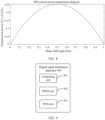
- the DAB converter may use a single phase shift (Single phase shift, SPS) control mode. As shown in FIG. 8 , in the SPS control mode, due to a special power transmission equation of the DAB converter, a phase shift angle of the DAB converter cannot exceed 90°. In addition, to reserve a margin of 30%, the phase shift angle of the DAB converter during rated operation is generally set to less than or equal to 45°.
- SPS single phase shift
- a digital chip is used as a PWM generator to generate a PWM signal to control the DAB converter.
- the digital chip may be a chip in STM32G4 series.
- a clock frequency of the PWM signal generated by the digital chip is 170 MHz.
- the value k of the phase shift register determines a value of a duty cycle k/n of the PWM signal generated by the digital chip, that is, the value k determines a power transmission magnitude of the DAB converter.
- the duty cycle k/n of the PWM signal needs to be modulated, so as to improve a duty cycle precision of the PWM signal.
- a PWM/PFM hybrid modulation method is used to calculate a phase-shift duty cycle required by the DAB converter in each working state, determine the values of k and n that are closest to the phase-shift duty cycle, generate PWM signals through pulse width modulation, and then modulate a PWM signal in each period through pulse frequency modulation, so as to output a PWM signal with a higher phase-shift precision.
- Pulse width modulation is performed based on the modulation value k of the comparator and the value n of the phase shift register (comparator) that are obtained by rounding.
- a deviation between the phase shift duty cycle after pulse frequency modulation and the phase shift duty cycle required for the DAB converter to be in the rated working state is 0, and a phase shift angle deviation is 0°.
- a duty cycle precision of a single-period PWM signal after pulse frequency modulation is obviously higher than the duty cycle precision before pulse frequency modulation.
- the switching frequency (a frequency of a PWM signal) of the DAB converter is 100 KHz x 1700/1696 ⁇ 100.24 KHz.
- the phase-shift angle output to the DAB converter is 4.5°
- Pulse width modulation is performed based on the modulation value k of the comparator and the value n of the phase shift register (comparator) that are obtained by rounding.
- a deviation between the phase shift duty cycle after pulse frequency modulation and the phase shift duty cycle required for the DAB converter to be in the rated working state is 0, and a phase shift angle deviation is 0°.
- the switching frequency (a frequency of a PWM signal) of the DAB converter is 100 KHz x 1700/1680 ⁇ 100.19 KHz.
- the duty cycle precision of the PWM signal output through modulation is obviously higher than the duty cycle precision of a conventional PWM signal output through pulse width modulation, and a relative deviation of the phase shift angle is smaller.
- a frequency fluctuation range of the PWM signal caused by pulse frequency modulation is relatively small, design difficulty of a filter circuit is not increased, and the working of the DAB converter is not significantly affected.
- the duty cycle precision of a PWM signal in a single period can be improved, and the duty cycle resolution of the PWM signal can be greatly improved.
- FIG. 9 is a schematic diagram depicting a structure of a digital signal modulation apparatus according to an embodiment of this application.
- the digital signal modulation apparatus 900 includes:
- the digital signal modulation apparatus 900 may be applied to any high-frequency power converter or power converter that is digitally controlled and uses a duty cycle or a phase shift angle to control output power, including but not limited to a buck/boost (boost and buck) circuit, a phase-shift full-bridge circuit, a forward circuit, a flyback circuit, an inverter circuit, and the like.
- a buck/boost (boost and buck) circuit a phase-shift full-bridge circuit
- forward circuit a flyback circuit
- inverter circuit and the like.
- the target duty cycle used by the calculation unit 901 is a most precise duty cycle for achieving a working output target.
- a target duty cycle required for accurately outputting the working voltage may be determined based on a working voltage and a rated voltage that need to be output by the power converter.
- the modulation value and the calibration value of the comparator that needs to reach the target duty cycle may be obtained through calculation based on the target duty cycle and the initial value of the counter of a digital PWM generator.
- the modulation value of the comparator refers to a value that needs to be set by the comparator
- the calibration value refers to a value required for performing addition modulation and subtraction modulation when pulse frequency modulation is performed on the PWM signal.
- the modulation value and the calibration value of the comparator need to be integers that can be reached on a premise that modulation precision is met.
- the calculation specifically includes:
- a precise comparator value is obtained through calculation based on the target duty cycle and the initial value of the counter.
- the precise comparator value is defined as an accurate value of the comparator. If the accurate value of the comparator is a value with a decimal place, the accurate value of the comparator needs to be rounded to obtain a modulation value of the comparator for pulse width modulation.
- a ratio of the modulation value of the comparator to the initial value of the counter still has a specific deviation from the target duty cycle.
- further calculation may be performed based on the accurate value of the comparator, the modulation value of the comparator, and the initial value of the counter, to obtain a calibration value for pulse frequency modulation.
- a process of calculating the calibration value needs to refer to a value of a duty cycle of a PWM signal, and the calculation process is performed based on a principle of obtaining a maximum calibration value.
- the modulation value of the comparator is used as a denominator for calculation, and a first precision value is obtained through calculation based on a difference between the modulation value of the comparator and the accurate value of the comparator, the modulation value of the comparator, and the initial value of the counter. If the first precision value is a value with a decimal place, the first precision value needs to be rounded to obtain a first calibration value used for pulse frequency modulation.
- the duty cycle of the PWM signal is greater than or equal to 0.5, that is, when the modulation value of the comparator is greater than or equal to half of the initial value of the counter
- a difference between the initial value of the counter and the modulation value of the comparator is used as a denominator for calculation, and a second precision value is obtained through calculation based on the difference between the modulation value of the comparator and the accurate value of the comparator, the difference between the modulation value of the comparator and the initial value of the counter, and the initial value of the counter.
- the second precision value is a value with a decimal place, the second precision value needs to be rounded to obtain a second calibration value used for pulse frequency modulation.
- the accurate value of the comparator, an integer value closest to the first precision value, and an integer value closest to the second precision value may be respectively obtained by using a round-off method, so as to implement more accurate pulse width modulation and pulse frequency modulation.
- Pulse width modulation and pulse frequency modulation may be performed based on the modulation value of the comparator, the first calibration value, and second calibration value that are obtained through calculation. Specifically:
- pulse width modulation is performed, and the digital PWM generator is set based on the modulation value of the comparator and the initial value of the counter, to generate periodic PWM signals.
- polarity reversal is configured for an output PWM signal in this embodiment of this application, and a duty cycle of a PWM signal in each period is a ratio of the modulation value of the comparator to the initial value of the counter.
- the following describes a pulse frequency modulation process of the PWM signal in each period. It can be learned from FIG. 3 that, when k ⁇ n/2, that is, when the duty cycle is less than 0.5, a duty cycle dispersion in case of high-level fixed-length pulse frequency modulation is smaller. On the contrary, when k ⁇ n/2, that is, when the duty cycle is greater than or equal to 0.5, a duty cycle dispersion in case of low-level fixed-length pulse frequency modulation is smaller. Therefore, based on the duty cycle of the PWM signal, the following pulse frequency modulation is performed on the PWM signal in each period in the periodic PWM signals:
- the duty cycle of the PWM signal is less than 0.5, performing addition modulation on the initial value of the counter of the PWM signal in each period based on the first calibration value, that is, adding the first calibration value to the initial value of the counter to obtain a final value of the counter; if the duty cycle of the PWM signal is greater than or equal to 0.5, performing subtraction modulation on the initial value of the counter and the modulation value of the comparator of the PWM signal in each period based on the second calibration value, that is, subtracting the second calibration value from the modulation value of the comparator and the initial value of the counter respectively, to obtain a final value of the comparator and a final value of the counter.
- FIG. 10 is a schematic diagram of a structure of a computing device 1000 according to an embodiment of this application.
- the computing device 1000 includes a processor 1010, a memory 1020, a communications interface 1030, and a bus 1040.
- communications interface 1030 in the computing device 1000 shown in FIG. 10 may be used for communication with another device.
- the processor 1010 may be connected to the memory 1020.
- the memory 1020 may be configured to store program code and data. Therefore, the memory 1020 may be an internal storage module of the processor 1010, may be an external storage module independent of the processor 1010, or may be a component that includes an internal storage module of the processor 1010 and an external storage module independent of the processor 1010.
- the computing device 1000 may further include the bus 1040.
- the memory 1020 and the communications interface 1030 may be connected to the processor 1010 through the bus 1040.
- the bus 1040 may be a peripheral component interconnect (Peripheral Component Interconnect, PCI) bus, an extended industry standard architecture (Extended Industry Standard Architecture, EISA) bus, or the like.
- PCI peripheral component interconnect
- EISA Extended Industry Standard Architecture
- the bus 1040 may be classified into an address bus, a data bus, a control bus, or the like. For ease of indication, the bus is indicated by using only one line in FIG. 10 . However, it does not indicate that there is only one bus or only one type of bus.
- the processor 1010 may be a central processing unit (central processing unit, CPU).
- the processor may be alternatively a general-purpose processor, a digital signal processor (digital signal processor, DSP), an application-specific integrated circuit (application-specific integrated circuit, ASIC), a field programmable gate array (field programmable gate array, FPGA) or another programmable logic device, a discrete gate or transistor logic device, or a discrete hardware component.
- the general-purpose processor may be a microprocessor, or the processor may be any conventional processor, or the like.
- the processor 1010 uses one or more integrated circuits, and is configured to execute a related program, to implement a technical solution provided in this embodiment of this application.
- the memory 1020 may include a read-only memory and a random access memory, and provides instructions and data to the processor 1010.
- a part of the processor 1010 may further include a non-volatile random access memory.
- the processor 1010 may further store device type information.
- the processor 1010 executes computer-executable instructions in the memory 1020 to perform the steps of the foregoing method.
- computing device 1000 may correspond to a corresponding execution body of the method according to embodiments of this application, and the foregoing and other operations and/or functions of modules in the computing device 1000 are separately intended to implement corresponding procedures of the methods in embodiments. For brevity, details are not described herein again.
- the disclosed system, apparatus, and method may be implemented in other manners.
- the described apparatus embodiments are merely examples.
- division into the units is merely logical function division and may be other division in actual implementation.
- a plurality of units or components may be combined or integrated into another system, or some features may be ignored or not performed.
- the displayed or discussed mutual couplings or direct couplings or communication connections may be implemented by using some interfaces.
- the indirect couplings or communication connections between the apparatuses or units may be implemented in electronic, mechanical, or other forms.
- the units described as separate parts may or may not be physically separate, and parts displayed as units may or may not be physical units, may be located in one position, or may be distributed on a plurality of network units. Some or all of the units may be selected based on actual requirements to achieve the objectives of the solutions of embodiments.
- the function When the function is implemented in a form of a software functional unit and sold or used as an independent product, the function may be stored in a computer-readable storage medium. Based on such an understanding, the technical solutions of this application essentially, or the part contributing to the conventional technology, or some of the technical solutions may be implemented in a form of a software product.
- the computer software product is stored in a storage medium, and includes several instructions for instructing a computer device (which may be a personal computer, a server, or a network device) to perform all or some of the steps of the methods described in embodiments of this application.
- the foregoing storage medium includes any medium that can store program code, like a USB flash drive, a removable hard disk, a read-only memory (Read-Only Memory, ROM), a random access memory (Random Access Memory, RAM), a magnetic disk, or a compact disc.
- program code like a USB flash drive, a removable hard disk, a read-only memory (Read-Only Memory, ROM), a random access memory (Random Access Memory, RAM), a magnetic disk, or a compact disc.
- An embodiment of this application further provides a computer-readable storage medium.
- the computer-readable storage medium stores a computer program, and when the program is executed by a processor, the program is used to perform a diversity problem generation method.
- the method includes at least one of the solutions described in the foregoing embodiments.
- the computer storage medium in this embodiment of this application may be any combination of one or more read-only media.
- the read-only medium may be a read-only signal medium or a computer-readable storage medium.
- the computer-readable storage medium may be, but is not limited to, an electric, magnetic, optical, electromagnetic, infrared, or semiconductor system, apparatus, or device, or any combination thereof.
- the computer-readable storage medium includes an electrical connection having one or more wires, a portable computer disk, a hard disk, a random access memory (RAM), a read-only memory (ROM), an erasable programmable read-only memory (EPROM or flash memory), an optical fiber, a portable compact disk read-only memory (CD-ROM), an optical storage device, a magnetic storage device, or any proper combination thereof.
- the computer-readable storage medium may be any tangible medium that includes or stores a program, and the program may be used by or in combination with an instruction execution system, apparatus, or device.
- the read-only signal medium may include a data signal propagated in a baseband or propagated as part of a carrier, where the data signal carries read-only program code.
- the propagated data signal may be in a plurality of forms, including but not limited to an electromagnetic signal, an optical signal, or any appropriate combination thereof.
- the read-only signal medium may alternatively be any read-only medium other than the computer-readable storage medium.
- the read-only medium may send, propagate, or transmit a program used by or in combination with an instruction execution system, apparatus, or device.
- Program code included in the read-only medium may be transmitted by using any proper medium, including but not limited to wireless, an electric wire, an optical cable, RF, or any proper combination thereof.
- Computer program code used to perform operations in this application may be written in one or more program design languages or a combination thereof.
- the program design language includes an object-oriented program design language like Java, Smalltalk, and C++, and further includes a conventional procedural program design language like a "C" language or a similar program design language.
- the program code may be executed entirely on a user computer, or some may be executed on a user computer as a separate software package, or some may be executed on a user computer while some is executed on a remote computer, or the code may be entirely executed on a remote computer or a server.
- the remote computer may be connected to a user computer by using any type of network, including a local area network (LAN) or a wide area network (WAN), or may be connected to an external computer (for example, connected by using an Internet service provider through the Internet).
- LAN local area network
- WAN wide area network
- an external computer for example, connected by using an Internet service provider through the Internet.
Landscapes
- Engineering & Computer Science (AREA)
- Power Engineering (AREA)
- Physics & Mathematics (AREA)
- General Physics & Mathematics (AREA)
- Automation & Control Theory (AREA)
- Electromagnetism (AREA)
- Dc-Dc Converters (AREA)
Applications Claiming Priority (1)
| Application Number | Priority Date | Filing Date | Title |
|---|---|---|---|
| PCT/CN2020/141431 WO2022141206A1 (zh) | 2020-12-30 | 2020-12-30 | 一种数字信号的调制方法及装置、开关电源控制方法及开关电源 |
Publications (2)
| Publication Number | Publication Date |
|---|---|
| EP4254751A1 true EP4254751A1 (de) | 2023-10-04 |
| EP4254751A4 EP4254751A4 (de) | 2024-02-07 |
Family
ID=75699420
Family Applications (1)
| Application Number | Title | Priority Date | Filing Date |
|---|---|---|---|
| EP20967547.9A Pending EP4254751A4 (de) | 2020-12-30 | 2020-12-30 | Verfahren und vorrichtung zur modulation digitaler signale, steuerungsverfahren für schaltnetzteil und schaltnetzteil |
Country Status (3)
| Country | Link |
|---|---|
| EP (1) | EP4254751A4 (de) |
| CN (1) | CN112771456B (de) |
| WO (1) | WO2022141206A1 (de) |
Families Citing this family (8)
| Publication number | Priority date | Publication date | Assignee | Title |
|---|---|---|---|---|
| CN113630935B (zh) * | 2021-08-10 | 2024-06-25 | 上海艾为电子技术股份有限公司 | 一种降低电容啸叫的方法及装置 |
| CN114221642B (zh) * | 2022-02-22 | 2022-06-17 | 浙江地芯引力科技有限公司 | Pwm波生成及占空比控制方法、装置、定时器及设备 |
| CN116149223B (zh) * | 2023-02-07 | 2024-11-05 | 中国电子科技集团公司第五十四研究所 | 基于射频直采芯片的加速器低电平控制系统数字化方法 |
| CN116540614B (zh) * | 2023-07-04 | 2023-11-03 | 深圳砺驰半导体科技有限公司 | 信号控制方法、装置及电子设备 |
| CN119536456A (zh) * | 2023-08-29 | 2025-02-28 | 华为技术有限公司 | 电子设备的调频方法及电子设备 |
| CN118033383A (zh) * | 2024-04-11 | 2024-05-14 | 杭州芯云半导体技术有限公司 | Pwm波形的测试方法、装置及测试机 |
| CN118449539B (zh) * | 2024-04-30 | 2025-07-18 | 深圳市瀚强科技股份有限公司 | 射频信号调制电路、射频信号发生装置以及射频电源设备 |
| CN118523667B (zh) * | 2024-07-18 | 2024-10-01 | 禹创半导体(深圳)有限公司 | 一种电机pwm调制电路 |
Family Cites Families (11)
| Publication number | Priority date | Publication date | Assignee | Title |
|---|---|---|---|---|
| AU6370301A (en) * | 2001-06-15 | 2001-11-20 | Scherrer Inst Paul | Method for negative feedback controlling electrical power and negative feedback controlled power supply |
| US6995592B2 (en) * | 2003-11-06 | 2006-02-07 | Stmicroelectronics Pvt. Ltd. | Method and system for generating variable frequency cyclic waveforms using pulse width modulation |
| US7098605B2 (en) * | 2004-01-15 | 2006-08-29 | Fairchild Semiconductor Corporation | Full digital dimming ballast for a fluorescent lamp |
| US7382114B2 (en) * | 2005-06-07 | 2008-06-03 | Intersil Americas Inc. | PFM-PWM DC-DC converter providing DC offset correction to PWM error amplifier and equalizing regulated voltage conditions when transitioning between PFM and PWM modes |
| US8558632B2 (en) * | 2011-09-29 | 2013-10-15 | Microchip Technology Incorporated | Repetitive single cycle pulse width modulation generation |
| CN102739209B (zh) * | 2012-07-09 | 2015-02-18 | 成都启臣微电子有限公司 | 时钟脉冲宽度调制电路和时钟脉冲宽度调制方法 |
| US9621036B2 (en) * | 2014-01-09 | 2017-04-11 | Allegro Microsystems, Llc | Circuits and techniques for improving regulation in a regulator having more than one mode of operation |
| DE102014218010A1 (de) * | 2014-09-09 | 2016-03-10 | Robert Bosch Gmbh | Vorrichtung und Verfahren zum Erzeugen eines Signals mit einem einstellbaren Tastverhältnis |
| CN104767431B (zh) * | 2015-04-02 | 2018-08-28 | 上海晶丰明源半导体股份有限公司 | 一种直流无刷电机脉冲宽度调制的控制方法、装置和系统 |
| CN108512421B (zh) * | 2018-04-24 | 2019-08-27 | 上海推拓科技有限公司 | 一种pfwm控制方法 |
| CN111049369B (zh) * | 2019-12-25 | 2021-03-16 | 湖北工业大学 | 一种用于分布式电源系统中谐振变换器的混合控制方法 |
-
2020
- 2020-12-30 EP EP20967547.9A patent/EP4254751A4/de active Pending
- 2020-12-30 CN CN202080004269.0A patent/CN112771456B/zh active Active
- 2020-12-30 WO PCT/CN2020/141431 patent/WO2022141206A1/zh not_active Ceased
Also Published As
| Publication number | Publication date |
|---|---|
| WO2022141206A1 (zh) | 2022-07-07 |
| EP4254751A4 (de) | 2024-02-07 |
| CN112771456B (zh) | 2022-05-31 |
| CN112771456A (zh) | 2021-05-07 |
Similar Documents
| Publication | Publication Date | Title |
|---|---|---|
| EP4254751A1 (de) | Verfahren und vorrichtung zur modulation digitaler signale, steuerungsverfahren für schaltnetzteil und schaltnetzteil | |
| US11569731B2 (en) | Control method for an AC-DC conversion circuit | |
| JP6688138B2 (ja) | 負荷応答ジッタ | |
| US9450499B2 (en) | Electric power conversion circuit system | |
| JP5928913B2 (ja) | 共振形dc−dcコンバータの制御装置 | |
| JP5826780B2 (ja) | 電力変換回路システム | |
| EP2104217A2 (de) | Motorsteuerung | |
| EP4109728A1 (de) | Leistungswandler, verfahren zum erhöhen des inversen verstärkungsbereichs, gerät und medium | |
| EP2838187A2 (de) | Resonanzwandler und Betriebsverfahren dafür | |
| US11870352B2 (en) | Dual active bridge converter control with intra-bridge phase shift | |
| CN103078492A (zh) | 谐振变换器的控制方法和装置 | |
| US12143024B2 (en) | Sensorless prediction method of overcurrent in isolated bidirectional DC-DC converter | |
| CN101753034A (zh) | 功率变换器的瞬变处理机制 | |
| US20160105120A1 (en) | Power conversion apparatus | |
| US20140268960A1 (en) | Method and system for power conversion | |
| CN120262862A (zh) | 一种高频llc的调频与移相混合调制方法和相关装置 | |
| CN116742948B (zh) | 一种三相pfc电路的调制方法、系统、设备和介质 | |
| JP6189814B2 (ja) | 電力変換装置 | |
| US20240332951A1 (en) | Method for adaptively adjusting pwm duty cycle, circuit and motor driving system | |
| Sankaranarayanan et al. | Online efficiency optimization of a closed-loop controlled SiC-based boost converter | |
| US12580472B2 (en) | Apparatus and method for controlling bidirectional resonant DC-DC converters | |
| US20150028825A1 (en) | Control Circuit, Control Method, DC-DC Converter and Electronic Device | |
| JP7492441B2 (ja) | スイッチング電源装置、その制御装置及び制御方法 | |
| Zhou et al. | A Control Strategy with Pulse Skipping and Optimal Trajectory for Efficiency Improvement of Dual-Bridge Series Resonant Converter Under Light-Load or Non-Unity-Gain Conditions | |
| KR102903001B1 (ko) | 전력변환장치의 출력전류 추정 장치 및 방법 |
Legal Events
| Date | Code | Title | Description |
|---|---|---|---|
| STAA | Information on the status of an ep patent application or granted ep patent |
Free format text: STATUS: THE INTERNATIONAL PUBLICATION HAS BEEN MADE |
|
| PUAI | Public reference made under article 153(3) epc to a published international application that has entered the european phase |
Free format text: ORIGINAL CODE: 0009012 |
|
| STAA | Information on the status of an ep patent application or granted ep patent |
Free format text: STATUS: REQUEST FOR EXAMINATION WAS MADE |
|
| 17P | Request for examination filed |
Effective date: 20230630 |
|
| AK | Designated contracting states |
Kind code of ref document: A1 Designated state(s): AL AT BE BG CH CY CZ DE DK EE ES FI FR GB GR HR HU IE IS IT LI LT LU LV MC MK MT NL NO PL PT RO RS SE SI SK SM TR |
|
| A4 | Supplementary search report drawn up and despatched |
Effective date: 20240109 |
|
| RIC1 | Information provided on ipc code assigned before grant |
Ipc: H03K 7/08 20060101ALI20240103BHEP Ipc: H02M 3/335 20060101ALI20240103BHEP Ipc: G05B 19/042 20060101ALI20240103BHEP Ipc: H02M 1/44 20070101ALI20240103BHEP Ipc: H03K 21/38 20060101ALI20240103BHEP Ipc: H03K 3/017 20060101ALI20240103BHEP Ipc: H02M 1/00 20060101AFI20240103BHEP |
|
| DAV | Request for validation of the european patent (deleted) | ||
| DAX | Request for extension of the european patent (deleted) | ||
| RAP1 | Party data changed (applicant data changed or rights of an application transferred) |
Owner name: SHENZHEN YINWANG INTELLIGENTTECHNOLOGIES CO., LTD. |