EP4252881A2 - Verwandelbares spielzeug - Google Patents
Verwandelbares spielzeug Download PDFInfo
- Publication number
- EP4252881A2 EP4252881A2 EP23180438.6A EP23180438A EP4252881A2 EP 4252881 A2 EP4252881 A2 EP 4252881A2 EP 23180438 A EP23180438 A EP 23180438A EP 4252881 A2 EP4252881 A2 EP 4252881A2
- Authority
- EP
- European Patent Office
- Prior art keywords
- rotary
- barrier
- transformable toy
- rotary member
- indicia
- Prior art date
- Legal status (The legal status is an assumption and is not a legal conclusion. Google has not performed a legal analysis and makes no representation as to the accuracy of the status listed.)
- Granted
Links
Images


Classifications
-
- A—HUMAN NECESSITIES
- A63—SPORTS; GAMES; AMUSEMENTS
- A63H—TOYS, e.g. TOPS, DOLLS, HOOPS OR BUILDING BLOCKS
- A63H33/00—Other toys
- A63H33/003—Convertible toys, e.g. robots convertible into rockets or vehicles convertible into planes
-
- A—HUMAN NECESSITIES
- A63—SPORTS; GAMES; AMUSEMENTS
- A63H—TOYS, e.g. TOPS, DOLLS, HOOPS OR BUILDING BLOCKS
- A63H3/00—Dolls
- A63H3/04—Dolls with deformable framework
-
- A—HUMAN NECESSITIES
- A63—SPORTS; GAMES; AMUSEMENTS
- A63H—TOYS, e.g. TOPS, DOLLS, HOOPS OR BUILDING BLOCKS
- A63H3/00—Dolls
- A63H3/12—Double-faced dolls
-
- A—HUMAN NECESSITIES
- A63—SPORTS; GAMES; AMUSEMENTS
- A63H—TOYS, e.g. TOPS, DOLLS, HOOPS OR BUILDING BLOCKS
- A63H3/00—Dolls
- A63H3/36—Details; Accessories
-
- A—HUMAN NECESSITIES
- A63—SPORTS; GAMES; AMUSEMENTS
- A63H—TOYS, e.g. TOPS, DOLLS, HOOPS OR BUILDING BLOCKS
- A63H3/00—Dolls
- A63H3/36—Details; Accessories
- A63H3/365—Details; Accessories allowing a choice of facial features, e.g. to change the facial expression
-
- A—HUMAN NECESSITIES
- A63—SPORTS; GAMES; AMUSEMENTS
- A63H—TOYS, e.g. TOPS, DOLLS, HOOPS OR BUILDING BLOCKS
- A63H33/00—Other toys
- A63H33/26—Magnetic or electric toys
Definitions
- the specification relates generally to transformable toys and more particularly to transformable toy that can be rolled when in a first state.
- a transformable toy which includes a first rotary member and a second rotary member.
- the first and second rotary members are rotatable relative to one another between a first rotary position and a second rotary position.
- the transformable toy further includes a projection member that is rotationally fixed to the first rotary member, and is movable between a retracted position and an extended position relative to the first rotary member.
- the transformable toy further includes a helical guide that is connected to one of the second rotary member and the projection member, and a helical guide follower that is connected to the other of the second rotary member and the projection member. Relative rotation between the first rotary member and the second rotary member between the first and second rotary positions drives relative rotation between the helical guide and the helical guide follower, which in turn drives the projection member to move between the retracted and extended positions.
- a transformable toy which includes a first rotary member and a second rotary member.
- the first and second rotary members are rotatable relative to one another between a first rotary position and a second rotary position, and between the second rotary position and a third rotary position.
- a barrier is provided and is movable between a blocking position and a release position. In the blocking position, the barrier prevents relative rotation between the first and second rotary members past the second rotary position. In the release position, the barrier permits relative rotation between the first and second rotary members past the second rotary position to the third rotary position.
- a barrier biasing member is provided and urges the barrier from a first of the blocking and release positions towards a second of the blocking and release positions, and a barrier holder that is movable between a holding position in which the barrier holder holds the barrier in the first of the blocking and release positions and a travel position in which the barrier holder permits movement of the barrier from the first of the blocking and release positions to the second of the blocking and release positions.
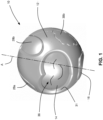
- Figure 1 shows a transformable toy 10 in accordance with an embodiment of the present disclosure.
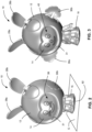
- the transformable toy 10 is positionable in a first state shown in Figure 1 , a second state shown in Figure 2 , and a third state shown in Figure 3 .
- the transformable toy 10 may be rollable on a support surface G shown in Figure 10 .
- the transformable toy 10 may be in the form of a rollable character in the first state.
- the transformable toy 10 may be in the form of an animal character.
- the transformable toy 10 may be in the form of a human character. It will be noted that the transformable toy 10 could be in any form in any of the three states and that the three states described above are only non-limiting examples.
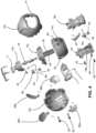
- the transformable toy 10 includes a first rotary member 12, a second rotary member 14, and a projection member 16.
- the transformable toy 10 optionally further includes a main biasing member 17, a helical guide 18, a helical guide follower 20, a barrier 22, a barrier biasing member 24, a latch member 26, and a plurality of flip up appendages 28a, 28b, 30a and 30b.
- the transformable toy 10 could, for example, include the helical guide 18 and the helical guide follower 20, but could include none, some or all of the other optional components.
- the transformable toy 10 could, for example, include the barrier 22 and the barrier biasing member 24, but could include none, some or all of the other optional components.
- the transformable toy 10 could, for example, include the latch member 26, but could include none, some or all of the other optional components. In another, non-limiting, example, the transformable toy 10 could include none of the optional components noted above.
- the first and second rotary members 12 and 14 are rotatable relative to one another (about an axis A) between a first rotary position ( Figure 1 ) and a second rotary position ( Figure 2 ), and optionally may be further rotatable relative to one another between the second rotary position and a third rotary position ( Figure 3 ).
- the first rotary member 12 is an outer rotary member and the second rotary member 14 is an inner rotary member, wherein a portion of the inner rotary member is visible through the outer rotary member.
- a pass-through aperture 31 is provided in the first rotary member 12 for this purpose.
- a transparent or semi-transparent window could be provided which permits the second (inner) rotary member 14 to be visible through the first (outer) rotary member 12.
- the rotary member 14 may be considered to the first rotary member and the rotary member 12 may be considered to be the second rotary member, in which case the first rotary member 14 would be the inner rotary member and the second rotary member 12 would be the outer rotary member.
- the first rotary member 12 includes a first portion 12a, a second portion 12b and a third portion 12c, which are all connected together in any suitable way, such as via mechanical fasteners shown at 32.
- the second rotary member 14 includes a first portion 14a and a second portion 14b.
- the second portion 14b of the second rotary member 14 and the first portion 14a of the second rotary member 14 are rotationally connected to one another by means of a drive arm 34 that extends from the second portion 14b of the second rotary member 14 and fits in a drive slot 35 on the first portion 14a of the second rotary member 14.
- the drive arm 34 and the drive slot 35 permits the first and second portions 14a and 14b to be rotationally connected to one another, while permitting relative movement axially between the first and second portions 14a and 14b.
- the second rotary member 14 may include first indicia 36 ( Figure 1 ), and second indicia 38 ( Figure 2 ), and may include third indicia 40 ( Figure 3 ), in embodiments wherein there is a third rotary position.
- the first indicia 36 may be first facial features representing a first facial expression, and are visible when the first and second rotary members 12 and 14 are in the first rotary position, as shown in Figure 1 .
- the first facial features represent a smiling face with its eyes closed.
- the second indicia 38 may be second facial features representing a second facial expression, and are visible when the first and second rotary members 12 and 14 are in the second rotary position, as shown in Figure 2 .
- the second indicia may be positioned about 90 degrees angularly away from the first indicia 36 on the second rotary member 14.
- the second facial features represent a smiling animal caricature face with its eyes open.
- the third indicia 40 may be third facial features representing a third facial expression, and are visible when the first and second rotary members 12 and 14 are in the third rotary position, as shown in Figure 3 .
- the third facial features represent a smiling person's caricature face with its eyes open.
- the main biasing member 17 ( Figures 4 and 5 ) is positioned to urge the first and second rotary members 12 and 14 towards the second rotary position. It will be noted that, in the embodiment shown, in which the first and second rotary members 12 and 14 are positionable in the third rotary position, the main biasing member 17 also may be said to be positioned to urge the first and second rotary members towards the third rotary position. For example, when the first and second rotary members 12 and 14 are between the first and second rotary positions, the main biasing member 17 may be said to be positioned to urge the first and second rotary members towards the second rotary position (or may also be said to urge the rotary members towards the third rotary position).
- the main biasing member 17 may be, for example, a torsion spring, as shown in Figures 4 and 5 , that has a first torsion spring end 17a ( Figure 5 ) that is connected to the first rotary member 12 and a second torsion spring end 17b that is connected to the second rotary member 14. More specifically, in the example shown, the first torsion spring end 17a is connected to the third portion 12c of the first rotary member 12 by passing through a slot 42 therein and the second torsion spring end 17b is connected to the second portion 14b of the second rotary member 14 by engagement about a post 44 thereon.
- a torsion spring as shown in Figures 4 and 5 , that has a first torsion spring end 17a ( Figure 5 ) that is connected to the first rotary member 12 and a second torsion spring end 17b that is connected to the second rotary member 14. More specifically, in the example shown, the first torsion spring end 17a is connected to the third portion 12c of the first rotary member 12 by passing through
- the projection member 16 is rotationally fixed to the first rotary member 12, and is movable between a retracted position ( Figure 1 ) and an extended position ( Figure 2 ) relative to the first rotary member 12.
- the extended position shown in Figure 2 for the projection member 16 is a first extended position
- the projection member 16 is further movable between the first extended position of Figure 2 and a second extended position ( Figure 3 ) relative to the first rotary member 12.
- the projection member 16 extends farther out from the first rotary member 12 when in the second extended position, then when it is in the first extended position, and farther out from the first rotary member 12 when in the first extended position, then when in the retracted position.
- the projection member 16 need not be retracted completely into the first rotary member 12.
- some of the projection member 16 extends out slightly from the first rotary member 12. In other embodiments, however, it is possible for the projection member 16 to be completely retracted within the first rotary member 12, when in the retracted position.
- the projection member 16 may be made from a plurality of components, including a first portion 16a and a second portion 16b that may be connected together by any suitable way, such as by mechanical fasteners 46.
- the projection member 16 may represent a body of the character whose head is represented by the first and/or second rotary member 12 and 14.
- the first portion 16a may be a front part of the body, while the second portion 16b may be a rear part of the body.
- Relative rotation between the first and second rotary members 12 and 14 between the first and second rotary positions drives movement of the projection member 16 between the retracted and extended positions. If the first and second rotary members 12 and 14 are movable to the third rotary position, then relative rotation between the first and second rotary members 12 and 14 between the first and second rotary positions, drives movement of the projection member 16 between the first extended and second extended positions.
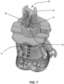
- the helical guide 18 and the helical guide follower 20 link relative rotational movement between the first and second rotary members 12 and 14 with extension and retraction of the projection member 16 relative to the first rotary member 12.
- the helical guide 18 is connected to one of the second rotary member 14 and the projection member 16, and the helical guide follower 20 is connected to the projection member 16.
- the helical guide 18 is connected to the second rotary member 14 (e.g. to the second portion 14b of the second rotary member 14 by means of a mechanical fastener 47) and the helical guide follower 20 is a first of two helical guide followers 20 ( Figure 7 ), which are connected respectively to the first and second portions 16a and 16b of the projection member 16.
- the first rotary member 12 (specifically the third portion 12c of the first rotary member 12) may have a linear movement guide 48 that includes a follower constraint slot 50 for each helical guide follower 20 that is provided.
- there are two follower constraint slots 50 each of which constrains one of the two helical guide followers 20 to move axially while engaged with the helical guide member 18.
- the follower constraint slots 50 and the helical guide followers 20 may be what rotationally fix the projection member 16 to the first rotary member 12.
- the latch member 26 is used to hold the transformable toy 10 in the first state.
- the latch member 26 is movable between a latching position ( Figure 8 ) and an unlatching position ( Figure 9 ).
- the latch member 26 In the latching position, the latch member 26 is engageable with a latching shoulder 52 to prevent movement of the projection member 16 towards one of the extended and retracted positions.
- the unlatching position In the unlatching position the latch member 26 permits movement of the projection member 16 towards the extended position.
- the latch member 26 includes a first magnetically-interactive member 54 and is positioned to move to the unlatching position upon approach of the transformable toy 10 with a second magnetically-interactive member (shown at 56 in Figure 9 ) that is external to the transformable toy 10.
- the latch member 26 further includes a hook portion 56 that is engageable with the latching shoulder 52.
- a magnetically-interactive member (such as the first and second magnetically-interactive members 54 and 56) is a member that is caused to move in the presence of a magnet.
- a magnetically-interactive member could be a piece of ferromagnetic material, or for example, it could be a magnet itself. It will be understood that at least one of the first and second magnetically-interactive members 54 and 56 would be a magnet, while the other of the first and second magnetically-interactive members 54 and 56 may be a magnet, or may be an object that interacts with a magnet, such as a ferromagnetic member.
- the first magnetically-interactive member 54 is a magnet
- the second magnetically-interactive member 56 is a piece of ferromagnetic material, such as steel, that is embedded in a platform member 58 whose upper surface is the support surface G.
- the latch member 26 and the latching shoulder 52 may be provided on any suitable combination of elements.
- the latch member 26 is connected to the projection member 16, and the latching shoulder 52 is connected to the first rotary member 12 (specifically to the linear movement guide 48).
- the latch member 26 may be connected to the first rotary member 12, and the latching shoulder 52 may be connected to the second rotary member 14 in order to prevent relative rotation therebetween.
- the latch member 26 may be connected to the second rotary member 12, and the latching shoulder 52 may be connected to the projection member 16 in order to prevent relative linear movement therebetween. Since the movement between the first rotary member 12, the second rotary member 14 and the projection member 16 are all interconnected, the latch member 26 and the latching shoulder 52 may be provided on any combination of two of these three elements.
- the latch member 26 may be pivotably connected (e.g. via a pin joint 60) to whatever component it is connected to (e.g. the projection member), so as to be pivotably movable between the latching and unlatching positions.
- the transformable toy 10 when the projection member 16 is in the retracted position ( Figure 1 ), the transformable toy 10 is rollable on the support surface G (optionally with the intent of trying to get the transformable toy 10 to roll over the second magnetically-interactive member 56, as illustrated in Figure 10 , while oriented so that the first magnetically-interactive member 54 is sufficiently close to the second magnetically-interactive member 56 to cause the unlatching of the latch member 26). and when the projection member is in the extended position ( Figure 2 ), the projection member 16 has a ground engagement surface 62 ( Figure 9 ) and may optionally positioned to solely support the transformable toy 10 on the support surface G via the ground engagement surface 62 ( Figure 2 ).
- the optionally provided barrier 22 is movable between a blocking position shown in Figures 11 and 12 , and a release position shown in Figure 13 .
- the barrier 22 prevents relative rotation between the first and second rotary members 12 and 14 past the second rotary position ( Figures 2 , 11 and 12 ) and movement of the projection member past the first extended position ( Figures 2 and 11 ).
- the barrier 22 permits relative rotation between the first and second rotary members 12 and 14 past the second rotary position to the third rotary position ( Figures 3 and 13 ) and movement of the projection member 16 past the first extended position to the second extended position ( Figures 3 and 13 ).
- the barrier biasing member 24 urges the barrier 22 from a first of the blocking and release positions towards a second of the blocking and release positions. In the example embodiment shown, the barrier biasing member 24 urges the barrier 22 towards the blocking position. In the embodiment shown, the barrier biasing member 24 is a helical compression spring but could be any other suitable type of biasing member.
- a barrier holder 64 may be provided and is movable between a holding position ( Figure 13 ) in which the barrier holder 64 holds the barrier 22 in the first of the blocking and release positions (in the example shown, the release position) against a biasing force applied by the barrier biasing member 24, and a travel position ( Figure 12 ) in which the barrier holder 64 permits movement of the barrier 22 from the first of the blocking and release positions to the second of the blocking and release positions (in the example shown, movement from the release position to the blocking position).
- the barrier holder 64 is a resilient member that is fixedly held in a barrier housing 66 ( Figure 4 ).
- the barrier housing 66 may be fixedly mountable to the third portion 12c of the first rotary member 12.
- the barrier holder 64 has an engagement end 68 that is best seen in Figure 4 but which is identified in Figures 12 and 13 even though it is somewhat obscured by the rest of the barrier holder 64.
- the barrier 22 itself includes several barrier holder guide surfaces shown at 70, 72, 74, 76, and 78.
- a first direction e.g. upwards in the view shown in Figure 12 , towards its release position
- it will drive the first barrier holder guide surface 72 into engagement with the barrier holder 64, which will drive the engagement end of the barrier holder towards the left in the view shown in Figure 12 .
- Further movement of the barrier 22 in the first direction will then bring the engagement end 68 around the locking projection shown at 80 (which has some of the aforementioned guide surfaces on it).
- the fourth barrier holder guide surface 76 is brought into engagement with the barrier holder 64 (i.e. with the engagement end 68), which guides the engagement end 68 over to the right of the locking projection 80.
- the barrier biasing member 24 drives the barrier 22 in the second direction (i.e. downward in the view shown), at which point the engagement end 68 passes around the right side of the locking projection 80, and engages the fifth barrier holder guide surface 78, which guides the engagement end 68 back towards the neutral position shown in both Figures 12 and 13 (i.e. a generally centered position).
- an actuation surface 84 may be provided on the projection member 16 ( Figures 13 and 14 ).
- the user can push down on the first and second rotary members 12 and 14 to cause retraction of the projection member 16 into the first rotary member 12, which brings the actuation surface 84 upwards into engagement with the barrier 22 ( Figure 14 ), thereby toggling the barrier 22 to the other of whichever of the blocking and release positions it is in.
- the main biasing member 17 then urges the first and second rotary members 12 and 14 back towards whichever rotational position they can reach depending on whether the latch member 26 is engaged with the latching shoulder 52, and depending on the position of the barrier 22 after it has been actuated.
- the appendages 28a and 28b and 30a and 30b may be actuated to flip up via biasing members (e.g. torsion springs) as needed.
- biasing members e.g. torsion springs
- transformable toy 10 does not include a projection member but includes the first and second rotary members 12 and 14, which are movable between the first, second and third rotary positions and which employs the barrier 22 to block relative movement of the first and second rotary members 12 and 14 past the second rotary position.
Landscapes
- Health & Medical Sciences (AREA)
- General Health & Medical Sciences (AREA)
- Oral & Maxillofacial Surgery (AREA)
- Toys (AREA)
Applications Claiming Priority (2)
| Application Number | Priority Date | Filing Date | Title |
|---|---|---|---|
| US17/362,981 US11376515B1 (en) | 2021-06-29 | 2021-06-29 | Transformable toy |
| EP21184776.9A EP4112146B1 (de) | 2021-06-29 | 2021-07-09 | Verwandelbares spielzeug |
Related Parent Applications (2)
| Application Number | Title | Priority Date | Filing Date |
|---|---|---|---|
| EP21184776.9A Division EP4112146B1 (de) | 2021-06-29 | 2021-07-09 | Verwandelbares spielzeug |
| EP21184776.9A Division-Into EP4112146B1 (de) | 2021-06-29 | 2021-07-09 | Verwandelbares spielzeug |
Publications (4)
| Publication Number | Publication Date |
|---|---|
| EP4252881A2 true EP4252881A2 (de) | 2023-10-04 |
| EP4252881A3 EP4252881A3 (de) | 2024-01-03 |
| EP4252881C0 EP4252881C0 (de) | 2025-03-26 |
| EP4252881B1 EP4252881B1 (de) | 2025-03-26 |
Family
ID=76859503
Family Applications (2)
| Application Number | Title | Priority Date | Filing Date |
|---|---|---|---|
| EP23180438.6A Active EP4252881B1 (de) | 2021-06-29 | 2021-07-09 | Verwandelbares spielzeug |
| EP21184776.9A Active EP4112146B1 (de) | 2021-06-29 | 2021-07-09 | Verwandelbares spielzeug |
Family Applications After (1)
| Application Number | Title | Priority Date | Filing Date |
|---|---|---|---|
| EP21184776.9A Active EP4112146B1 (de) | 2021-06-29 | 2021-07-09 | Verwandelbares spielzeug |
Country Status (4)
| Country | Link |
|---|---|
| US (2) | US11376515B1 (de) |
| EP (2) | EP4252881B1 (de) |
| CN (2) | CN115607976A (de) |
| ES (1) | ES2964103T3 (de) |
Families Citing this family (9)
| Publication number | Priority date | Publication date | Assignee | Title |
|---|---|---|---|---|
| JP4859206B2 (ja) * | 2006-02-20 | 2012-01-25 | 株式会社セガ トイズ | 玩具 |
| WO2018222736A1 (en) * | 2017-05-30 | 2018-12-06 | Paul Joanna | Toy with multiple face expressions |
| DK4037793T3 (da) * | 2019-10-01 | 2023-12-18 | Lego As | Transformerbart modulært legetøjselement |
| USD1029155S1 (en) * | 2021-06-25 | 2024-05-28 | Spin Master Ltd. | Toy |
| JP7081026B1 (ja) * | 2021-06-25 | 2022-06-06 | 株式会社バンダイ | 玩具 |
| US11376515B1 (en) * | 2021-06-29 | 2022-07-05 | Spin Master Ltd. | Transformable toy |
| CN218793864U (zh) * | 2022-11-30 | 2023-04-07 | 深圳市北朋科技有限公司 | 一种具有隐藏摆杆的玩具 |
| US12011675B1 (en) * | 2023-03-31 | 2024-06-18 | DiscoNifty Ltd. | Rotationally transformable toy between a first configuration and a second configuration |
| US12134045B1 (en) | 2023-05-03 | 2024-11-05 | Mattel, Inc. | Adjustable toy figure |
Family Cites Families (70)
| Publication number | Priority date | Publication date | Assignee | Title |
|---|---|---|---|---|
| US1387224A (en) * | 1920-07-08 | 1921-08-09 | Ahler Edwin Arthur | Doll |
| US1610724A (en) * | 1925-09-16 | 1926-12-14 | Samuel E Wilson | Multiple-face figure toy |
| GB374362A (en) * | 1931-08-22 | 1932-06-09 | Carl Arnold | Means for spinning tops and for projecting flying toys of propeller form |
| US1985716A (en) * | 1933-01-25 | 1934-12-25 | Essex Specialty Co Inc | Top |
| US2584789A (en) * | 1950-03-07 | 1952-02-05 | Ibm | Automatic clamping device |
| US2584798A (en) * | 1950-11-09 | 1952-02-05 | Goerditz Hans | Multiple faced doll |
| US2968121A (en) * | 1958-04-04 | 1961-01-17 | Glass | Toy |
| US3032921A (en) * | 1960-03-29 | 1962-05-08 | Norman A Greene | Toy |
| US4030239A (en) * | 1976-01-29 | 1977-06-21 | Mattel, Inc. | Multiple face doll |
| US4605381A (en) * | 1983-12-29 | 1986-08-12 | Mattel, Inc. | Animated figure toy having a unitary, multiple-function spring |
| JPS60175292U (ja) * | 1984-04-26 | 1985-11-20 | 株式会社トミー | 重力式回転機構 |
| US4639232A (en) * | 1985-03-01 | 1987-01-27 | Cheng Chung Wang | Toy having an envelope enclosing a moving mechanism |
| USD292725S (en) | 1985-06-26 | 1987-11-10 | Kenner Parker Toys Inc. | Toy figure |
| US4773889A (en) * | 1985-11-13 | 1988-09-27 | Marvin Glass & Associates | Wheel for a toy vehicle |
| US5169354A (en) * | 1991-05-29 | 1992-12-08 | Fisher-Price, Inc. | Self-righting toy carousel |
| US5902169A (en) * | 1997-12-17 | 1999-05-11 | Dah Yang Toy Industrial Co., Ltd | Toy with changing facial expression |
| US5893789A (en) * | 1998-01-15 | 1999-04-13 | Wu; Li-Hsiung | Sphere toy |
| USD464382S1 (en) | 2000-09-28 | 2002-10-15 | Trendmasters, Inc. | Toy |
| US6530499B1 (en) * | 2001-09-28 | 2003-03-11 | Thomas J. Coleman | Dispensing amusement device |
| US7306504B2 (en) | 2004-07-12 | 2007-12-11 | Spin Master, Ltd. | Transformable toy |
| JP4859206B2 (ja) | 2006-02-20 | 2012-01-25 | 株式会社セガ トイズ | 玩具 |
| CA116665S (en) | 2006-02-20 | 2008-06-13 | Spin Master Ltd | Transformable toy |
| WO2009087881A1 (ja) | 2008-01-10 | 2009-07-16 | Sega Toys Co., Ltd. | 玩具 |
| JP2009189521A (ja) | 2008-02-14 | 2009-08-27 | Tomy Co Ltd | 形態変化玩具 |
| JP4598839B2 (ja) | 2008-03-17 | 2010-12-15 | 株式会社タカラトミー | 形態変化玩具 |
| EP2294066B9 (de) * | 2008-04-28 | 2015-03-11 | Janssen Pharmaceutica, N.V. | Benzoimidazole als prolyl hydroxylase inhibitoren |
| EP2116289A1 (de) * | 2008-05-09 | 2009-11-11 | Produzioni Editoriali Aprile S.p.A. | Verwandelbares Spielzeug |
| USD620991S1 (en) | 2009-09-28 | 2010-08-03 | Jorge Pozo | Toy figure |
| JP2011120756A (ja) * | 2009-12-11 | 2011-06-23 | Tomy Co Ltd | 形態変化玩具 |
| KR200471569Y1 (ko) * | 2010-01-28 | 2014-03-06 | 동아교재 주식회사 | 인출식 고형 마커 |
| EP2470278B1 (de) | 2010-07-09 | 2018-06-13 | Jakks Pacific, Inc. | Kern mit fingervertiefung zum herausdrücken eines darin verborgenen objekts |
| USD632999S1 (en) | 2010-08-18 | 2011-02-22 | Frank Yeh | Coconut monkey |
| US20120309262A1 (en) * | 2011-06-03 | 2012-12-06 | Daizo Uehara | Collectable helmet with interactive features |
| US8985881B2 (en) * | 2011-07-07 | 2015-03-24 | Il Makiage Cosmetics (2013) Ltd | Lipstick tube |
| CN202438149U (zh) * | 2011-11-18 | 2012-09-19 | 广东奥飞动漫文化股份有限公司 | 一种可旋转变换的玩具 |
| KR101327305B1 (ko) * | 2012-02-24 | 2013-11-11 | 최신규 | 변신 자동차 완구 및 이를 이용한 놀이 장치 |
| US20150238880A1 (en) | 2014-02-27 | 2015-08-27 | John Austin | Multiple Use Anthropomorphic Bouncing Ball Action Figure Toy |
| USD746384S1 (en) | 2014-07-07 | 2015-12-29 | Jesal Kantawala | Guided meditation toy |
| KR101746917B1 (ko) | 2015-05-11 | 2017-06-27 | 최종일 | 팝업 완구 |
| US20160361661A1 (en) * | 2015-06-11 | 2016-12-15 | Simeon E. Tiefel | Toy Convertible Between a Character and a High-Bounce Ball |
| KR101635319B1 (ko) | 2015-06-12 | 2016-06-30 | 최종일 | 변신 완구 |
| KR101722676B1 (ko) * | 2015-09-04 | 2017-04-04 | (주)짐월드 | 장난감 블록 |
| KR101859804B1 (ko) | 2015-11-20 | 2018-05-18 | 최종일 | 분리형 완구 |
| KR101815357B1 (ko) | 2015-12-07 | 2018-01-30 | 최종일 | 발사형 완구 |
| KR101815363B1 (ko) | 2016-01-13 | 2018-01-08 | 최종일 | 발사장치를 구비한 다단 변신 완구 |
| USD847914S1 (en) | 2016-04-22 | 2019-05-07 | Groove X, Inc. | Robot |
| USD822742S1 (en) | 2016-09-09 | 2018-07-10 | Netgear, Inc. | Baby monitor camera |
| USD822743S1 (en) | 2016-09-09 | 2018-07-10 | Netgear, Inc. | Baby monitor camera |
| CN206404318U (zh) * | 2016-12-22 | 2017-08-15 | 奥飞娱乐股份有限公司 | 变形机器人 |
| TWD188692S (zh) | 2017-05-19 | 2018-02-21 | 隆宸星股份有限公司 | robot |
| TWD188693S (zh) | 2017-05-19 | 2018-02-21 | 隆宸星股份有限公司 | robot |
| WO2018222736A1 (en) * | 2017-05-30 | 2018-12-06 | Paul Joanna | Toy with multiple face expressions |
| US10695687B2 (en) * | 2017-10-03 | 2020-06-30 | Darwin William Fernandez | Model Toy croms balls |
| US11219839B2 (en) | 2017-12-06 | 2022-01-11 | Darwin William Fernandez | Button activated transformable rotating toy |
| US10864452B2 (en) | 2018-01-22 | 2020-12-15 | Darwin William Fernandez | Toy with two bodies and an ejectable gear and retraction mechanism |
| US20190236978A1 (en) * | 2018-01-31 | 2019-08-01 | Marcinda Falls | Educational doll assembly |
| JP1630931S (de) | 2018-06-04 | 2019-05-13 | ||
| USD868907S1 (en) | 2018-06-13 | 2019-12-03 | Shantou Jiabaile Baby Products Co., Ltd. | Toy robot |
| CN208591533U (zh) * | 2018-07-09 | 2019-03-12 | 张嘉篪 | 一种电动变脸人偶玩具 |
| KR102030937B1 (ko) | 2018-09-21 | 2019-10-10 | 주식회사 초이락컨텐츠팩토리 | 변신완구 |
| USD961692S1 (en) | 2020-04-27 | 2022-08-23 | Embodied, Inc. | Robot |
| USD973152S1 (en) | 2020-07-28 | 2022-12-20 | Cj Cheiljedang Corporation | Doll |
| US11376515B1 (en) * | 2021-06-29 | 2022-07-05 | Spin Master Ltd. | Transformable toy |
| USD994201S1 (en) | 2021-12-24 | 2023-08-01 | YunFu Hongrui Intelligent Equipment Co., Ltd | Projector |
| CA210700S (en) | 2022-02-17 | 2023-08-28 | Shenzhen Bolong Tech Co Ltd | Starry projector lamp |
| USD983281S1 (en) | 2023-01-10 | 2023-04-11 | Shuchen Cai | Toy animal |
| USD999971S1 (en) | 2023-03-31 | 2023-09-26 | Shenzhen Huijing Technology Co., Ltd. | Moon night lamp |
| USD999970S1 (en) | 2023-04-12 | 2023-09-26 | Pingji Lai | Astronaut light |
| USD999435S1 (en) | 2023-04-21 | 2023-09-19 | Shenzhen Huipin Design Co., Ltd | Lunar rover astronaut projection lamp |
| USD1000683S1 (en) | 2023-06-02 | 2023-10-03 | Junjie Qin | Projection lamp |
-
2021
- 2021-06-29 US US17/362,981 patent/US11376515B1/en active Active
- 2021-07-09 EP EP23180438.6A patent/EP4252881B1/de active Active
- 2021-07-09 EP EP21184776.9A patent/EP4112146B1/de active Active
- 2021-07-09 ES ES21184776T patent/ES2964103T3/es active Active
- 2021-09-29 CN CN202111168257.4A patent/CN115607976A/zh active Pending
- 2021-09-29 CN CN202122378576.XU patent/CN216963534U/zh active Active
-
2022
- 2022-07-05 US US17/857,908 patent/US12285702B2/en active Active
Also Published As
| Publication number | Publication date |
|---|---|
| CN115607976A (zh) | 2023-01-17 |
| CN216963534U (zh) | 2022-07-15 |
| EP4252881C0 (de) | 2025-03-26 |
| ES2964103T3 (es) | 2024-04-04 |
| EP4252881B1 (de) | 2025-03-26 |
| EP4252881A3 (de) | 2024-01-03 |
| US11376515B1 (en) | 2022-07-05 |
| EP4112146B1 (de) | 2023-08-16 |
| US20220410025A1 (en) | 2022-12-29 |
| EP4112146A1 (de) | 2023-01-04 |
| US12285702B2 (en) | 2025-04-29 |
Similar Documents
| Publication | Publication Date | Title |
|---|---|---|
| US12285702B2 (en) | Transformable toy | |
| US12075577B2 (en) | Magnetic block locking of an electronic device | |
| CN104620337B (zh) | 磁性固定装置和连接器 | |
| US12543826B2 (en) | Kit of parts including elastic ring-based ornament making device, elastic ring, and plurality of ornamental members | |
| TW201238447A (en) | Portable electrical device | |
| JP2016532464A (ja) | 可動家具部材を移動させるための駆動機構 | |
| JP2015529291A (ja) | ロックを備えた完全埋め込み式のドアハンドル | |
| JPH0821134A (ja) | 調節ボタンを有する組み合わせ錠 | |
| HK40083936A (en) | Transformable toy | |
| HK40083936B (en) | Transformable toy | |
| CN103243992A (zh) | 门扇固定器 | |
| CN104950986B (zh) | 能够书写签名的自动机 | |
| GB2276482A (en) | Shopping trolley lock | |
| CN113789994A (zh) | 一种便于使用的磁铁锁 | |
| CN2499518Y (zh) | 一种锁具的锁心孔遮蔽装置 | |
| KR101886447B1 (ko) | 플러시글라스 | |
| JP3361486B2 (ja) | 商品展示ケースの施錠装置並びにその解錠装置 | |
| TWM339895U (en) | Hard disk box having hard-disk buffering withdrawal | |
| JP3677351B2 (ja) | 扉の補助錠 | |
| JP4456774B2 (ja) | 扉 | |
| JP2520300B2 (ja) | 左右両開扉装置 | |
| JPH0547278Y2 (de) | ||
| CN118815337A (zh) | 联动门系统 | |
| KR20100013622A (ko) | 2단 슬라이드형 화장품 케이스 | |
| CN114412280A (zh) | 锁体连动结构及锁体 |
Legal Events
| Date | Code | Title | Description |
|---|---|---|---|
| PUAI | Public reference made under article 153(3) epc to a published international application that has entered the european phase |
Free format text: ORIGINAL CODE: 0009012 |
|
| STAA | Information on the status of an ep patent application or granted ep patent |
Free format text: STATUS: THE APPLICATION HAS BEEN PUBLISHED |
|
| AC | Divisional application: reference to earlier application |
Ref document number: 4112146 Country of ref document: EP Kind code of ref document: P |
|
| AK | Designated contracting states |
Kind code of ref document: A2 Designated state(s): AL AT BE BG CH CY CZ DE DK EE ES FI FR GB GR HR HU IE IS IT LI LT LU LV MC MK MT NL NO PL PT RO RS SE SI SK SM TR |
|
| REG | Reference to a national code |
Ref country code: DE Ref legal event code: R079 Free format text: PREVIOUS MAIN CLASS: A63H0033000000 Ipc: A63H0003360000 Ref document number: 602021028339 Country of ref document: DE |
|
| PUAL | Search report despatched |
Free format text: ORIGINAL CODE: 0009013 |
|
| AK | Designated contracting states |
Kind code of ref document: A3 Designated state(s): AL AT BE BG CH CY CZ DE DK EE ES FI FR GB GR HR HU IE IS IT LI LT LU LV MC MK MT NL NO PL PT RO RS SE SI SK SM TR |
|
| RIC1 | Information provided on ipc code assigned before grant |
Ipc: A63H 33/00 20060101ALI20231129BHEP Ipc: A63H 3/36 20060101AFI20231129BHEP |
|
| STAA | Information on the status of an ep patent application or granted ep patent |
Free format text: STATUS: REQUEST FOR EXAMINATION WAS MADE |
|
| 17P | Request for examination filed |
Effective date: 20240624 |
|
| RBV | Designated contracting states (corrected) |
Designated state(s): AL AT BE BG CH CY CZ DE DK EE ES FI FR GB GR HR HU IE IS IT LI LT LU LV MC MK MT NL NO PL PT RO RS SE SI SK SM TR |
|
| GRAP | Despatch of communication of intention to grant a patent |
Free format text: ORIGINAL CODE: EPIDOSNIGR1 |
|
| STAA | Information on the status of an ep patent application or granted ep patent |
Free format text: STATUS: GRANT OF PATENT IS INTENDED |
|
| INTG | Intention to grant announced |
Effective date: 20241112 |
|
| GRAS | Grant fee paid |
Free format text: ORIGINAL CODE: EPIDOSNIGR3 |
|
| GRAA | (expected) grant |
Free format text: ORIGINAL CODE: 0009210 |
|
| STAA | Information on the status of an ep patent application or granted ep patent |
Free format text: STATUS: THE PATENT HAS BEEN GRANTED |
|
| AC | Divisional application: reference to earlier application |
Ref document number: 4112146 Country of ref document: EP Kind code of ref document: P |
|
| AK | Designated contracting states |
Kind code of ref document: B1 Designated state(s): AL AT BE BG CH CY CZ DE DK EE ES FI FR GB GR HR HU IE IS IT LI LT LU LV MC MK MT NL NO PL PT RO RS SE SI SK SM TR |
|
| REG | Reference to a national code |
Ref country code: GB Ref legal event code: FG4D |
|
| REG | Reference to a national code |
Ref country code: CH Ref legal event code: EP |
|
| REG | Reference to a national code |
Ref country code: DE Ref legal event code: R096 Ref document number: 602021028339 Country of ref document: DE |
|
| REG | Reference to a national code |
Ref country code: IE Ref legal event code: FG4D |
|
| U01 | Request for unitary effect filed |
Effective date: 20250423 |
|
| U07 | Unitary effect registered |
Designated state(s): AT BE BG DE DK EE FI FR IT LT LU LV MT NL PT RO SE SI Effective date: 20250429 |
|
| PG25 | Lapsed in a contracting state [announced via postgrant information from national office to epo] |
Ref country code: RS Free format text: LAPSE BECAUSE OF FAILURE TO SUBMIT A TRANSLATION OF THE DESCRIPTION OR TO PAY THE FEE WITHIN THE PRESCRIBED TIME-LIMIT Effective date: 20250626 |
|
| PG25 | Lapsed in a contracting state [announced via postgrant information from national office to epo] |
Ref country code: NO Free format text: LAPSE BECAUSE OF FAILURE TO SUBMIT A TRANSLATION OF THE DESCRIPTION OR TO PAY THE FEE WITHIN THE PRESCRIBED TIME-LIMIT Effective date: 20250626 |
|
| PG25 | Lapsed in a contracting state [announced via postgrant information from national office to epo] |
Ref country code: HR Free format text: LAPSE BECAUSE OF FAILURE TO SUBMIT A TRANSLATION OF THE DESCRIPTION OR TO PAY THE FEE WITHIN THE PRESCRIBED TIME-LIMIT Effective date: 20250326 |
|
| PG25 | Lapsed in a contracting state [announced via postgrant information from national office to epo] |
Ref country code: GR Free format text: LAPSE BECAUSE OF FAILURE TO SUBMIT A TRANSLATION OF THE DESCRIPTION OR TO PAY THE FEE WITHIN THE PRESCRIBED TIME-LIMIT Effective date: 20250627 |
|
| U20 | Renewal fee for the european patent with unitary effect paid |
Year of fee payment: 5 Effective date: 20250619 |
|
| PG25 | Lapsed in a contracting state [announced via postgrant information from national office to epo] |
Ref country code: SM Free format text: LAPSE BECAUSE OF FAILURE TO SUBMIT A TRANSLATION OF THE DESCRIPTION OR TO PAY THE FEE WITHIN THE PRESCRIBED TIME-LIMIT Effective date: 20250326 |
|
| PG25 | Lapsed in a contracting state [announced via postgrant information from national office to epo] |
Ref country code: ES Free format text: LAPSE BECAUSE OF FAILURE TO SUBMIT A TRANSLATION OF THE DESCRIPTION OR TO PAY THE FEE WITHIN THE PRESCRIBED TIME-LIMIT Effective date: 20250326 |
|
| PG25 | Lapsed in a contracting state [announced via postgrant information from national office to epo] |
Ref country code: PL Free format text: LAPSE BECAUSE OF FAILURE TO SUBMIT A TRANSLATION OF THE DESCRIPTION OR TO PAY THE FEE WITHIN THE PRESCRIBED TIME-LIMIT Effective date: 20250326 |
|
| PG25 | Lapsed in a contracting state [announced via postgrant information from national office to epo] |
Ref country code: SK Free format text: LAPSE BECAUSE OF FAILURE TO SUBMIT A TRANSLATION OF THE DESCRIPTION OR TO PAY THE FEE WITHIN THE PRESCRIBED TIME-LIMIT Effective date: 20250326 |
|
| PG25 | Lapsed in a contracting state [announced via postgrant information from national office to epo] |
Ref country code: IS Free format text: LAPSE BECAUSE OF FAILURE TO SUBMIT A TRANSLATION OF THE DESCRIPTION OR TO PAY THE FEE WITHIN THE PRESCRIBED TIME-LIMIT Effective date: 20250726 |
|
| PG25 | Lapsed in a contracting state [announced via postgrant information from national office to epo] |
Ref country code: CZ Free format text: LAPSE BECAUSE OF FAILURE TO SUBMIT A TRANSLATION OF THE DESCRIPTION OR TO PAY THE FEE WITHIN THE PRESCRIBED TIME-LIMIT Effective date: 20250326 |
|
| PLBE | No opposition filed within time limit |
Free format text: ORIGINAL CODE: 0009261 |
|
| STAA | Information on the status of an ep patent application or granted ep patent |
Free format text: STATUS: NO OPPOSITION FILED WITHIN TIME LIMIT |
|
| REG | Reference to a national code |
Ref country code: CH Ref legal event code: L10 Free format text: ST27 STATUS EVENT CODE: U-0-0-L10-L00 (AS PROVIDED BY THE NATIONAL OFFICE) Effective date: 20260211 |
|
| REG | Reference to a national code |
Ref country code: CH Ref legal event code: H13 Free format text: ST27 STATUS EVENT CODE: U-0-0-H10-H13 (AS PROVIDED BY THE NATIONAL OFFICE) Effective date: 20260224 |
|
| 26N | No opposition filed |
Effective date: 20260105 |
|
| GBPC | Gb: european patent ceased through non-payment of renewal fee |
Effective date: 20250709 |
|
| PG25 | Lapsed in a contracting state [announced via postgrant information from national office to epo] |
Ref country code: GB Free format text: LAPSE BECAUSE OF NON-PAYMENT OF DUE FEES Effective date: 20250709 |