EP4252589B1 - Lehnenvorrichtung für ein sitz- und/oder liegemöbelstück - Google Patents
Lehnenvorrichtung für ein sitz- und/oder liegemöbelstück Download PDFInfo
- Publication number
- EP4252589B1 EP4252589B1 EP23163487.4A EP23163487A EP4252589B1 EP 4252589 B1 EP4252589 B1 EP 4252589B1 EP 23163487 A EP23163487 A EP 23163487A EP 4252589 B1 EP4252589 B1 EP 4252589B1
- Authority
- EP
- European Patent Office
- Prior art keywords
- backrest
- headrest
- carrier part
- head rest
- backrest device
- Prior art date
- Legal status (The legal status is an assumption and is not a legal conclusion. Google has not performed a legal analysis and makes no representation as to the accuracy of the status listed.)
- Active
Links
Images


Classifications
-
- A—HUMAN NECESSITIES
- A47—FURNITURE; DOMESTIC ARTICLES OR APPLIANCES; COFFEE MILLS; SPICE MILLS; SUCTION CLEANERS IN GENERAL
- A47C—CHAIRS; SOFAS; BEDS
- A47C7/00—Parts, details, or accessories of chairs or stools
- A47C7/36—Supports for the head or the back
- A47C7/40—Supports for the head or the back for the back
-
- A—HUMAN NECESSITIES
- A47—FURNITURE; DOMESTIC ARTICLES OR APPLIANCES; COFFEE MILLS; SPICE MILLS; SUCTION CLEANERS IN GENERAL
- A47C—CHAIRS; SOFAS; BEDS
- A47C7/00—Parts, details, or accessories of chairs or stools
- A47C7/36—Supports for the head or the back
- A47C7/38—Supports for the head or the back for the head, e.g. detachable
Definitions
- the invention relates to a backrest device for a piece of furniture that is suitable for sitting and/or lying down.
- the invention also relates to a piece of furniture for sitting and/or lying down with such a backrest device and with a sitting or lying down element.
- Modern seating or reclining furniture sometimes provides adjustment options to increase comfort for the user.
- the adjustment options affect, for example, the user's head or back.
- the backrest device according to the invention is particularly aimed at designing the option of supporting the user's head and back in line with requirements and yet still offering an attractive appearance.
- the piece of seating and/or reclining furniture can in particular be an upholstered piece of furniture, such as an armchair, a sofa, a couch, a chaise longue or a chaise longue.
- the backrest device accordingly comprises upholstery elements.
- the backrest device comprises a backrest and a headrest.
- the headrest is adjustable relative to the backrest between a first (retracted) position and a second (extended) position. Specifically, this is the possibility of linear adjustment along a translation axis.
- the headrest has an overlap section that always overlaps with a part of the backrest, so that no gap is created between the backrest and the headrest when the headrest is in the first position, the second position and an intermediate position (between the first and second positions). This means that regardless of its position, the headrest always overlaps with a part of the backrest.
- the area of overlap along the translation axis is larger or smaller.
- the linear adjustment therefore enables the backrest device to be adapted to the user's height. Since there is no gap between the headrest and the backrest in any position of the headrest, the appearance is harmonious and the modular structure is not emphasized.
- the overlapping section is flat and extends in a main extension plane.
- the overlapping section extends over the entire width of the headrest.
- the overlapping section always overlaps with a part of the backrest, at least in the viewing direction perpendicular to the main extension plane.
- the overlapping section can be arranged with respect to the backrest in such a way that the overlapping section covers a part of the backrest (when viewed from a viewing direction on the side facing a user).
- the translation axis can lie in the main extension plane of the overlapping section of the headrest.
- the translation axis and the main extension plane can enclose an angle of less than 90°.
- the translation axis can lie in the main extension plane of the overlapping section.
- a plurality of intermediate positions are provided between the first position and the second position along the translation axis, which intermediate positions can be adjusted by linearly adjusting the headrest relative to the backrest along the translation axis.
- the headrest can be lockable or latchable in any of the first position, the second position and any intermediate position.
- the headrest can be pivoted about a rotation axis.
- the rotation axis can be directed essentially perpendicular to the translation axis and extend along the width of the headrest.
- the pivotability of the headrest makes it possible to adjust the inclination of the headrest relative to the backrest. Depending on the position of the headrest along the translation axis, the inclination for the head or for the upper body and the head as a whole can be adjusted.
- the linear adjustment is carried out manually in addition to the motor-driven linear adjustment described below.
- the headrest can be moved upwards in order to lock into one of the intermediate positions or into the second position.
- at least one rack can be provided which interacts with at least one gear.
- the at least one rack is aligned parallel to the translation axis.
- a locking fitting can be provided which enables locking in one of the positions mentioned.
- the backrest device comprises a motor for linear adjustment of the headrest, wherein the motor acts on the headrest via a carrier.
- the carrier comprises a first carrier part, which is firmly connected to the headrest, and a second carrier part, which can be moved linearly by the motor.
- the first carrier part and the second carrier part are detachably connected to one another. This means that the two carrier parts can be moved independently of one another under certain circumstances.
- the detachable connection is such that the first carrier part and the headrest connected to it can be moved with the second carrier part if the first carrier part and the second carrier part are connected to one another by means of the detachable connection, and that the first carrier part and the headrest connected to it cannot be moved with the second carrier part if the first carrier part and the second carrier part are not connected to one another by means of the detachable connection.
- This design can prevent the headrest and the first support part from moving with the second support part and, for example, injuring a user who is holding the headrest when the motor is operating and is about to effect a linear adjustment of the second support part from the second position to the first position.
- the detachable connection between the first support part and the second support part comprises a magnetic connection according to the invention.
- the motor may be concealed, in particular arranged in a housing formed in the backrest.
- Figure 1 shows a perspective view of a backrest device 100 and a section of a seat element 200, which together with the backrest device 100 forms a piece of seating furniture 1 in the form of a sofa.
- the seat element 200 comprises a seat surface 201.
- the seat surface 201 is upholstered.
- the backrest device 100 comprises a backrest 110 and a headrest 120.
- the backrest 110 and the headrest 120 are also upholstered.
- the headrest 120 is linearly displaceable relative to the backrest 110 along a translation axis T between a first (retracted) position and a second (extended) position.
- the headrest 120 can also assume one of several positions between the first and second positions and be locked in this position.
- Figure 1 the headrest 120 is shown in the first position.
- Figure 2 shows the backrest device 100 from Figure 1 , but with the headrest 120 in the second position.
- the headrest 120 always overlaps (both in the first and in the second position) with the backrest 110 in an overlap section 124.
- the extent of the overlap varies with the position of the headrest 120.
- the overlap section 124 always extends (i.e. regardless of the position of the headrest 120) over the entire width of the headrest 124.
- the extent of the overlap varies with the position of the headrest 120 only along the translation axis T.
- the headrest 120 is rotated about a rotation axis R pivotable to adjust the angle between the headrest 120 and the backrest 110.
- the rotation axis R extends substantially perpendicular to the translation axis T and along the width of the headrest 124.
- the headrest 120 is shown pivoted about the rotation axis R, the rotation starting from the second position of the headrest 120 ( Figure 2 ).
- the angle between the headrest 120 and the backrest 110 can vary between 0° and 40°.
- Several intermediate positions are provided. The headrest 120 can be locked (latched) in both the intermediate positions and the two outermost deflections.
- the angle between adjacent positions is 4° in each case. Consequently, eleven different inclinations of the headrest 120 can be set by rotating it about the axis of rotation R. Even if the angle between the headrest 120 and the backrest 110 varies, the headrest 120 always overlaps with the backrest 110 in an overlap section 124.
- the backrest device 100 is shown without upholstery.
- the backrest 110 and the headrest 120 each comprise a solid base body.
- the base body of the backrest 110 defines a receptacle 113.
- Two through-openings 111 are incorporated into the base body of the backrest 110, each of which serves to receive a guide shaft 121 that is arranged on the headrest 120.
- a plug-in sleeve 112 is arranged in each through-opening 111, which covers the corresponding through-opening 111 and offers defined sliding properties in relation to the guide shaft 121.
- the plug-in sleeve 112 is connected to the through-opening 111 in a form-fitting manner, for example by a (spring-mounted) projection 1121 at one end and a protruding decorative cap 1122 at another end ( Figure 13 ).
- the plug-in sleeve 112 is shown in detail in Figure 14 shown.
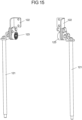
- Figure 15 shows a detailed view of the guide shafts 121.
- fittings 122 are arranged, which serve to attach the respective guide shaft 121 to the headrest 120.
- Each fitting 122 is attached to the respective guide shaft 121 via a joint 123.
- the fitting 122 and the joint 123 are designed together as a locking fitting.
- the guide shafts 121 are, as in Figure 13 shown, into the through-openings 111 with the plug sleeves 112.
- the translation mechanism 130 comprises two racks 131, each of which interacts with a gear 132.
- the racks 131 extend along the translation axis T. While the racks 131 are stationary, the gears 132 are adapted to move along the racks 131.
- the racks 131 are arranged at a distance from one another and are connected to one another via a first crossbar 133.
- the crossbar 133 is according to the Figures 6 and 7 for example, arranged in an end region of the racks 131.
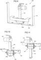
- FIG. 6 shows the translation mechanism 130 corresponding to the first position of the headrest 120. That is, when the headrest 120 is retracted.
- FIG. 7 shows the translation mechanism 130 corresponding to the second position of the headrest 120. That is, when the headrest 120 is extended. In this position, the second cross strut 134 is in its uppermost position. With the aid of the locking fitting 135, the second cross strut 134 can assume a variety of positions between the uppermost and the lowermost position, and thus the headrest 120 can be locked (locked) at different heights.
- the locking fitting 135 can comprise 23 locking positions.
- the height difference between the uppermost position of the second cross strut 134 and the lowermost position of the second cross strut 134 can be 15 cm. Other height differences are also conceivable.
- the headrest 120 In order to move the headrest 120 from a lower position to a higher position, it is sufficient to pull the headrest 120 upwards. In order to move the headrest 120 from a higher position to a lower position, the headrest 120 must first be brought into its second position (uppermost position of the second cross strut 134) in order to release the locking fitting 135 from its locking state, so that the headrest 120 can then move downwards into its first position (lowest position of the second cross strut 134).
- the backrest device 100 a translation mechanism 140 for a motor-driven linear adjustment of the headrest 120.
- This translation mechanism 140 is in its state built into the base body of the backrest 110 in Figure 8 shown.
- Figure 9 shows the translation mechanism 140 from Figure 8 alone.
- the translation mechanism 140 comprises a bracket 141, which is provided for fastening the translation mechanism 140 in the backrest 110.
- a motor 143 is fastened to the bracket 141 via a linear guide 142.
- the linear guide 142 extends along the translation axis T.
- the linear guide serves to guide a carrier 144, which in the embodiment of the Figures 9 to 12 is formed in two parts.
- the support 144 comprises a first support part 1441, which is connected to a crossbar 145 to which the headrest is attached, and a second support part 1442, which is linearly displaceable by the motor 143.
- the crossbar 145 extends transversely to the translation axis T and along the width of the headrest 124.
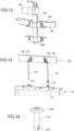
- Figure 9 illustrates the translation mechanism 140 in a configuration corresponding to the first position of the headrest 120.
- Figure 10 shows the translation mechanism 140 from Figure 9 without the bracket 141 and in a view rotated by 180° around the translation axis T.
- Figure 11 shows the translation mechanism 140 from Figure 10 , but the configuration corresponds to that of the second position of the headrest 120.
- the first and second carrier parts 1441, 1442 can be clearly seen.
- the motor 143 drives the second carrier part 1442.
- the first carrier part 1441 which is connected to the second carrier part 1442 via a detachable connection, moves together with the second carrier part 1442 ( Figures 10 and 11 ).
- the movement of the second support part 1442 can be decoupled from that of the headrest 120 (connected to the first support part 1441 via the cross strut 145) by applying a force ( Figure 12 ).
- the detachable connection is such that, on the one hand, the first carrier part 1441 and the headrest 120 connected to it can be moved with the second carrier part 1442 when the first carrier part 1441 and the second carrier part 1442 are connected to one another by means of the detachable connection, and that, on the other hand, the first carrier part 1441 and the headrest 120 connected to it cannot be moved with the second carrier part 1442 when the first carrier part 1441 and the second carrier part 1442 are not connected to one another by means of the detachable connection.
- the detachable connection By releasing the detachable connection, during operation of the motor 143, which causes a linear adjustment of the second carrier part 1442 in the direction of the first position of the headrest 120, that the headrest 120, the cross brace 145 and the first support part 1441 move with the second support part 1442. This can, for example, prevent a user who is holding the headrest 120 from being injured, in particular trapped, by the lowering headrest 120.
- the detachable connection thus has the function of a pinch protection.
- the detachable connection is designed, for example, as a magnetic connection.
- the magnetic connection can be such that it releases when a counterforce of 9 kg is applied, so that the second support part 1442 can be adjusted linearly by the motor 142, but the first support part 1441 does not move with the second support part 1442.
- the translation mechanism 130, 140 is arranged in the receptacle 113 of the backrest 110.
Landscapes
- Chair Legs, Seat Parts, And Backrests (AREA)
Applications Claiming Priority (1)
| Application Number | Priority Date | Filing Date | Title |
|---|---|---|---|
| DE202022101771.9U DE202022101771U1 (de) | 2022-04-01 | 2022-04-01 | Lehnenvorrichtung für ein Sitz- und/oder Liegemöbelstück |
Publications (3)
| Publication Number | Publication Date |
|---|---|
| EP4252589A1 EP4252589A1 (de) | 2023-10-04 |
| EP4252589C0 EP4252589C0 (de) | 2025-01-22 |
| EP4252589B1 true EP4252589B1 (de) | 2025-01-22 |
Family
ID=81345297
Family Applications (1)
| Application Number | Title | Priority Date | Filing Date |
|---|---|---|---|
| EP23163487.4A Active EP4252589B1 (de) | 2022-04-01 | 2023-03-22 | Lehnenvorrichtung für ein sitz- und/oder liegemöbelstück |
Country Status (3)
| Country | Link |
|---|---|
| EP (1) | EP4252589B1 (pl) |
| DE (1) | DE202022101771U1 (pl) |
| PL (1) | PL4252589T3 (pl) |
Family Cites Families (5)
| Publication number | Priority date | Publication date | Assignee | Title |
|---|---|---|---|---|
| SE420394B (sv) * | 1979-06-08 | 1981-10-05 | Saab Scania Ab | Nackskydd for en stol, foretredesvis en fordonsstol |
| US6779839B2 (en) * | 2001-10-23 | 2004-08-24 | Lear Corporation | Flip head restraint |
| US7458640B1 (en) * | 2005-09-22 | 2008-12-02 | Hill Gregory C | Adjustable vehicle headrest assembly |
| DE102018101721A1 (de) * | 2018-01-25 | 2019-07-25 | Ferdinand Lusch Gmbh & Co. Kg | Sitzmöbel mit höhenverstellbarem Kopfteil |
| DE202020106922U1 (de) * | 2020-12-01 | 2021-02-02 | Stanzwerk Wetter Sichelschmidt Gmbh & Co. Kg | Sitzmöbel |
-
2022
- 2022-04-01 DE DE202022101771.9U patent/DE202022101771U1/de active Active
-
2023
- 2023-03-22 PL PL23163487.4T patent/PL4252589T3/pl unknown
- 2023-03-22 EP EP23163487.4A patent/EP4252589B1/de active Active
Also Published As
| Publication number | Publication date |
|---|---|
| DE202022101771U1 (de) | 2022-04-07 |
| PL4252589T3 (pl) | 2025-04-28 |
| EP4252589C0 (de) | 2025-01-22 |
| EP4252589A1 (de) | 2023-10-04 |
Similar Documents
| Publication | Publication Date | Title |
|---|---|---|
| EP3167763A1 (de) | Sitzmöbel mit einem separaten und schwenkbaren kopfteil | |
| EP0943482A2 (de) | Anordnung von zumindest zwei nebeneinander angeordneten Sitzen, insbesondere eine Sitzreihe eines Kraftfahrzeuges | |
| DE2419483C3 (de) | Sitzmöbel mit Nackenstatze | |
| WO2006074764A2 (de) | Sessel | |
| EP0943483A2 (de) | Sitanordnung mit zumindest zwei nebeneinander angeordneten Sitzen | |
| EP4252589B1 (de) | Lehnenvorrichtung für ein sitz- und/oder liegemöbelstück | |
| EP1256484A1 (de) | Fahrzeugtür mit Armauflage | |
| WO2022218761A1 (de) | Schwenkbeschlag und sitz- oder liegevorrichtung | |
| DE202007010189U1 (de) | Umwandelbares Sitz-Liegemöbel | |
| DE20207018U1 (de) | Variables Sitz- und Liegemöbel | |
| DE29617255U1 (de) | Polstermöbelelement | |
| DE102020124190B4 (de) | Mehrteiliger Beschlag für ein Sitz- und/oder Liegemöbel, Sitz und/oder Liegemöbel, Verfahren zur Benutzung und Verwendung des mehrteiligen Beschlags | |
| DE202017102905U1 (de) | Lattenrost | |
| DE102005023241B4 (de) | Sitz- und/oder Liegemöbel | |
| DE20108172U1 (de) | Stuhl mit Rückenlehne, die zur Einstellung der Sitztiefe relativ gegenüber dem Sitzteil verstellbar ist | |
| EP3973822B1 (de) | Vorrichtung zur befestigung und zum verstellen einer kopfstütze | |
| AT400917B (de) | Verriegelung für stützfüsse von polsterauflagen von sitz- und liegemöbeln | |
| EP4458218B1 (de) | Sitzmöbel | |
| DE9011737U1 (de) | In eine Liege umwandelbares Sitzmöbel | |
| EP3586678B1 (de) | Möbel | |
| DE20215899U1 (de) | In ein Liegemöbel verwandelbares Sitzmöbel | |
| EP1516564B1 (de) | Verstellbares Sitz-/Liegemöbel | |
| EP1112707B1 (de) | Sitz-und/oder Liegevorrichtung | |
| EP1836933B1 (de) | In ein Bett umwandelbares Sitzmöbel | |
| EP4458211A1 (de) | Möbelanordnung |
Legal Events
| Date | Code | Title | Description |
|---|---|---|---|
| PUAI | Public reference made under article 153(3) epc to a published international application that has entered the european phase |
Free format text: ORIGINAL CODE: 0009012 |
|
| STAA | Information on the status of an ep patent application or granted ep patent |
Free format text: STATUS: THE APPLICATION HAS BEEN PUBLISHED |
|
| AK | Designated contracting states |
Kind code of ref document: A1 Designated state(s): AL AT BE BG CH CY CZ DE DK EE ES FI FR GB GR HR HU IE IS IT LI LT LU LV MC ME MK MT NL NO PL PT RO RS SE SI SK SM TR |
|
| STAA | Information on the status of an ep patent application or granted ep patent |
Free format text: STATUS: REQUEST FOR EXAMINATION WAS MADE |
|
| 17P | Request for examination filed |
Effective date: 20240404 |
|
| RBV | Designated contracting states (corrected) |
Designated state(s): AL AT BE BG CH CY CZ DE DK EE ES FI FR GB GR HR HU IE IS IT LI LT LU LV MC ME MK MT NL NO PL PT RO RS SE SI SK SM TR |
|
| GRAP | Despatch of communication of intention to grant a patent |
Free format text: ORIGINAL CODE: EPIDOSNIGR1 |
|
| STAA | Information on the status of an ep patent application or granted ep patent |
Free format text: STATUS: GRANT OF PATENT IS INTENDED |
|
| INTG | Intention to grant announced |
Effective date: 20240902 |
|
| GRAS | Grant fee paid |
Free format text: ORIGINAL CODE: EPIDOSNIGR3 |
|
| GRAA | (expected) grant |
Free format text: ORIGINAL CODE: 0009210 |
|
| STAA | Information on the status of an ep patent application or granted ep patent |
Free format text: STATUS: THE PATENT HAS BEEN GRANTED |
|
| RIN1 | Information on inventor provided before grant (corrected) |
Inventor name: WUSSLER, ARTUR |
|
| AK | Designated contracting states |
Kind code of ref document: B1 Designated state(s): AL AT BE BG CH CY CZ DE DK EE ES FI FR GB GR HR HU IE IS IT LI LT LU LV MC ME MK MT NL NO PL PT RO RS SE SI SK SM TR |
|
| REG | Reference to a national code |
Ref country code: GB Ref legal event code: FG4D Free format text: NOT ENGLISH |
|
| REG | Reference to a national code |
Ref country code: CH Ref legal event code: EP |
|
| REG | Reference to a national code |
Ref country code: IE Ref legal event code: FG4D Free format text: LANGUAGE OF EP DOCUMENT: GERMAN |
|
| REG | Reference to a national code |
Ref country code: DE Ref legal event code: R096 Ref document number: 502023000481 Country of ref document: DE |
|
| U01 | Request for unitary effect filed |
Effective date: 20250210 |
|
| U07 | Unitary effect registered |
Designated state(s): AT BE BG DE DK EE FI FR IT LT LU LV MT NL PT RO SE SI Effective date: 20250214 |
|
| U20 | Renewal fee for the european patent with unitary effect paid |
Year of fee payment: 3 Effective date: 20250327 |
|
| PG25 | Lapsed in a contracting state [announced via postgrant information from national office to epo] |
Ref country code: RS Free format text: LAPSE BECAUSE OF FAILURE TO SUBMIT A TRANSLATION OF THE DESCRIPTION OR TO PAY THE FEE WITHIN THE PRESCRIBED TIME-LIMIT Effective date: 20250422 |
|
| PGFP | Annual fee paid to national office [announced via postgrant information from national office to epo] |
Ref country code: PL Payment date: 20250321 Year of fee payment: 3 |
|
| PG25 | Lapsed in a contracting state [announced via postgrant information from national office to epo] |
Ref country code: ES Free format text: LAPSE BECAUSE OF FAILURE TO SUBMIT A TRANSLATION OF THE DESCRIPTION OR TO PAY THE FEE WITHIN THE PRESCRIBED TIME-LIMIT Effective date: 20250122 |
|
| PG25 | Lapsed in a contracting state [announced via postgrant information from national office to epo] |
Ref country code: IS Free format text: LAPSE BECAUSE OF FAILURE TO SUBMIT A TRANSLATION OF THE DESCRIPTION OR TO PAY THE FEE WITHIN THE PRESCRIBED TIME-LIMIT Effective date: 20250522 Ref country code: NO Free format text: LAPSE BECAUSE OF FAILURE TO SUBMIT A TRANSLATION OF THE DESCRIPTION OR TO PAY THE FEE WITHIN THE PRESCRIBED TIME-LIMIT Effective date: 20250422 |
|
| PG25 | Lapsed in a contracting state [announced via postgrant information from national office to epo] |
Ref country code: HR Free format text: LAPSE BECAUSE OF FAILURE TO SUBMIT A TRANSLATION OF THE DESCRIPTION OR TO PAY THE FEE WITHIN THE PRESCRIBED TIME-LIMIT Effective date: 20250122 |
|
| PG25 | Lapsed in a contracting state [announced via postgrant information from national office to epo] |
Ref country code: GR Free format text: LAPSE BECAUSE OF FAILURE TO SUBMIT A TRANSLATION OF THE DESCRIPTION OR TO PAY THE FEE WITHIN THE PRESCRIBED TIME-LIMIT Effective date: 20250423 |
|
| PG25 | Lapsed in a contracting state [announced via postgrant information from national office to epo] |
Ref country code: SM Free format text: LAPSE BECAUSE OF FAILURE TO SUBMIT A TRANSLATION OF THE DESCRIPTION OR TO PAY THE FEE WITHIN THE PRESCRIBED TIME-LIMIT Effective date: 20250122 |
|
| PG25 | Lapsed in a contracting state [announced via postgrant information from national office to epo] |
Ref country code: MC Free format text: LAPSE BECAUSE OF FAILURE TO SUBMIT A TRANSLATION OF THE DESCRIPTION OR TO PAY THE FEE WITHIN THE PRESCRIBED TIME-LIMIT Effective date: 20250122 |
|
| PG25 | Lapsed in a contracting state [announced via postgrant information from national office to epo] |
Ref country code: CZ Free format text: LAPSE BECAUSE OF FAILURE TO SUBMIT A TRANSLATION OF THE DESCRIPTION OR TO PAY THE FEE WITHIN THE PRESCRIBED TIME-LIMIT Effective date: 20250122 |
|
| PG25 | Lapsed in a contracting state [announced via postgrant information from national office to epo] |
Ref country code: SK Free format text: LAPSE BECAUSE OF FAILURE TO SUBMIT A TRANSLATION OF THE DESCRIPTION OR TO PAY THE FEE WITHIN THE PRESCRIBED TIME-LIMIT Effective date: 20250122 |
|
| PLBE | No opposition filed within time limit |
Free format text: ORIGINAL CODE: 0009261 |
|
| STAA | Information on the status of an ep patent application or granted ep patent |
Free format text: STATUS: NO OPPOSITION FILED WITHIN TIME LIMIT |
|
| 26N | No opposition filed |
Effective date: 20251023 |
|
| PG25 | Lapsed in a contracting state [announced via postgrant information from national office to epo] |
Ref country code: IE Free format text: LAPSE BECAUSE OF NON-PAYMENT OF DUE FEES Effective date: 20250322 |