EP4252301B1 - Electrode assembly - Google Patents
Electrode assembly Download PDFInfo
- Publication number
- EP4252301B1 EP4252301B1 EP22838068.9A EP22838068A EP4252301B1 EP 4252301 B1 EP4252301 B1 EP 4252301B1 EP 22838068 A EP22838068 A EP 22838068A EP 4252301 B1 EP4252301 B1 EP 4252301B1
- Authority
- EP
- European Patent Office
- Prior art keywords
- electrode
- separator
- separator portion
- electrodes
- electrode assembly
- Prior art date
- Legal status (The legal status is an assumption and is not a legal conclusion. Google has not performed a legal analysis and makes no representation as to the accuracy of the status listed.)
- Active
Links
Images

Classifications
-
- H—ELECTRICITY
- H01—ELECTRIC ELEMENTS
- H01M—PROCESSES OR MEANS, e.g. BATTERIES, FOR THE DIRECT CONVERSION OF CHEMICAL ENERGY INTO ELECTRICAL ENERGY
- H01M10/00—Secondary cells; Manufacture thereof
- H01M10/05—Accumulators with non-aqueous electrolyte
- H01M10/058—Construction or manufacture
- H01M10/0583—Construction or manufacture of accumulators with folded construction elements except wound ones, i.e. folded positive or negative electrodes or separators, e.g. with "Z"-shaped electrodes or separators
-
- H—ELECTRICITY
- H01—ELECTRIC ELEMENTS
- H01M—PROCESSES OR MEANS, e.g. BATTERIES, FOR THE DIRECT CONVERSION OF CHEMICAL ENERGY INTO ELECTRICAL ENERGY
- H01M10/00—Secondary cells; Manufacture thereof
- H01M10/04—Construction or manufacture in general
- H01M10/0404—Machines for assembling batteries
-
- H—ELECTRICITY
- H01—ELECTRIC ELEMENTS
- H01M—PROCESSES OR MEANS, e.g. BATTERIES, FOR THE DIRECT CONVERSION OF CHEMICAL ENERGY INTO ELECTRICAL ENERGY
- H01M10/00—Secondary cells; Manufacture thereof
- H01M10/04—Construction or manufacture in general
- H01M10/0459—Cells or batteries with folded separator between plate-like electrodes
-
- H—ELECTRICITY
- H01—ELECTRIC ELEMENTS
- H01M—PROCESSES OR MEANS, e.g. BATTERIES, FOR THE DIRECT CONVERSION OF CHEMICAL ENERGY INTO ELECTRICAL ENERGY
- H01M10/00—Secondary cells; Manufacture thereof
- H01M10/04—Construction or manufacture in general
- H01M10/0468—Compression means for stacks of electrodes and separators
-
- H—ELECTRICITY
- H01—ELECTRIC ELEMENTS
- H01M—PROCESSES OR MEANS, e.g. BATTERIES, FOR THE DIRECT CONVERSION OF CHEMICAL ENERGY INTO ELECTRICAL ENERGY
- H01M10/00—Secondary cells; Manufacture thereof
- H01M10/05—Accumulators with non-aqueous electrolyte
- H01M10/052—Li-accumulators
-
- H—ELECTRICITY
- H01—ELECTRIC ELEMENTS
- H01M—PROCESSES OR MEANS, e.g. BATTERIES, FOR THE DIRECT CONVERSION OF CHEMICAL ENERGY INTO ELECTRICAL ENERGY
- H01M50/00—Constructional details or processes of manufacture of the non-active parts of electrochemical cells other than fuel cells, e.g. hybrid cells
- H01M50/40—Separators; Membranes; Diaphragms; Spacing elements inside cells
- H01M50/46—Separators, membranes or diaphragms characterised by their combination with electrodes
-
- H—ELECTRICITY
- H01—ELECTRIC ELEMENTS
- H01M—PROCESSES OR MEANS, e.g. BATTERIES, FOR THE DIRECT CONVERSION OF CHEMICAL ENERGY INTO ELECTRICAL ENERGY
- H01M50/00—Constructional details or processes of manufacture of the non-active parts of electrochemical cells other than fuel cells, e.g. hybrid cells
- H01M50/40—Separators; Membranes; Diaphragms; Spacing elements inside cells
- H01M50/463—Separators, membranes or diaphragms characterised by their shape
- H01M50/466—U-shaped, bag-shaped or folded
-
- H—ELECTRICITY
- H01—ELECTRIC ELEMENTS
- H01M—PROCESSES OR MEANS, e.g. BATTERIES, FOR THE DIRECT CONVERSION OF CHEMICAL ENERGY INTO ELECTRICAL ENERGY
- H01M50/00—Constructional details or processes of manufacture of the non-active parts of electrochemical cells other than fuel cells, e.g. hybrid cells
- H01M50/40—Separators; Membranes; Diaphragms; Spacing elements inside cells
- H01M50/489—Separators, membranes, diaphragms or spacing elements inside the cells, characterised by their physical properties, e.g. swelling degree, hydrophilicity or shut down properties
-
- Y—GENERAL TAGGING OF NEW TECHNOLOGICAL DEVELOPMENTS; GENERAL TAGGING OF CROSS-SECTIONAL TECHNOLOGIES SPANNING OVER SEVERAL SECTIONS OF THE IPC; TECHNICAL SUBJECTS COVERED BY FORMER USPC CROSS-REFERENCE ART COLLECTIONS [XRACs] AND DIGESTS
- Y02—TECHNOLOGIES OR APPLICATIONS FOR MITIGATION OR ADAPTATION AGAINST CLIMATE CHANGE
- Y02E—REDUCTION OF GREENHOUSE GAS [GHG] EMISSIONS, RELATED TO ENERGY GENERATION, TRANSMISSION OR DISTRIBUTION
- Y02E60/00—Enabling technologies; Technologies with a potential or indirect contribution to GHG emissions mitigation
- Y02E60/10—Energy storage using batteries
-
- Y—GENERAL TAGGING OF NEW TECHNOLOGICAL DEVELOPMENTS; GENERAL TAGGING OF CROSS-SECTIONAL TECHNOLOGIES SPANNING OVER SEVERAL SECTIONS OF THE IPC; TECHNICAL SUBJECTS COVERED BY FORMER USPC CROSS-REFERENCE ART COLLECTIONS [XRACs] AND DIGESTS
- Y02—TECHNOLOGIES OR APPLICATIONS FOR MITIGATION OR ADAPTATION AGAINST CLIMATE CHANGE
- Y02P—CLIMATE CHANGE MITIGATION TECHNOLOGIES IN THE PRODUCTION OR PROCESSING OF GOODS
- Y02P70/00—Climate change mitigation technologies in the production process for final industrial or consumer products
- Y02P70/50—Manufacturing or production processes characterised by the final manufactured product
Definitions
- the present invention relates to an electrode assembly.
- Secondary batteries unlike primary batteries, are rechargeable, and have been widely researched and developed in recent years due to their small size and large capacity. As technology development and demand for mobile devices increase, the demand for secondary batteries as an energy source is rapidly increasing.
- Secondary batteries can be classified into a coin-type battery, a cylindrical battery, a prismatic battery, and a pouch-type battery, according to the shape of the battery case.
- an electrode assembly mounted inside a battery case is a chargeable/dischargeable power generating element having a stacked structure comprising electrodes and separators.
- the electrode assembly may be generally classified into a jelly-roll type, a stack type, and a stack-and-folding type.
- a separator is interposed between a sheet type positive electrode and a sheet type negative electrode, each of which are coated with an active material, and the entire arrangement is wound.
- the stack type a plurality of positive and negative electrodes are sequentially stacked with a separator interposed therebetween.
- stacked unit cells are wound with a long-length separation film.
- Korean Patent Application Laid-Open No. 10-2013-0132230 , KR 2020 0023853 , KR 2020 0023854 and JP 5 259453 relate to electrode assembly manufacturing device
- the present invention provides, among other things, an electrode assembly which has reduced deviations in adhesive force and air permeability across each layer, while still maintaining adequate adhesive force and air permeability.
- An exemplary aspect of the present invention provides an electrode assembly.
- An electrode assembly according to the invention is defined in claim 1.
- the separator portions may be portions of an elongated separator sheet.
- Such elongated separator sheet may be folded between each separator portion such that the elongated separator sheet follows a serpentine path traversing back and forth along an orthogonal dimension orthogonal to the stacking axis to extend between each of the successive electrodes in the stack.
- the electrode assembly according to exemplary aspects of the present invention is desirably capable of preventing side-effects, such as lithium (Li) precipitation in the electrode assembly and non-charging of the electrode assembly.
- the electrode assembly according to exemplary aspects of the present invention may also have uniform performance.
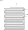
- FIG. 1 is a cross-sectional view illustrating an example of an electrode assembly according to an exemplary embodiment of the present invention. That is, referring to FIG. 1 , an electrode assembly 10 according to an exemplary embodiment of the present invention includes a stack of electrodes in which one or more first electrodes 11 alternates with one or more second electrodes 12. Each of the electrodes in the stack are separated from one another by a separator 14 positioned therebetween, which may be a single elongated separator 14 repeatedly folded so as to follow a serpentine or zigzag path around each successive electrode.
- the electrode assembly 10 is a chargeable/dischargeable power generating element, where the first electrode may be a positive electrode, and the second electrode may be a negative electrode. However, alternatively, the first electrode may be a negative electrode, and the second electrode may be a positive electrode. Moreover, the electrode assembly 10 may be provided in a form in which the outermost portion is surrounded by the separator 14, e.g., by wrapping the separator around the assembled electrode assembly 10, as illustrated in FIG. 1 . With respect to the electrodes and the separator comprising the electrode assembly, materials commonly used in the art may be used.
- an "upper surface” of the electrode assembly 10 refers to the uppermost position of the electrode assembly 10 in the stacking direction of the electrode assembly, which is designated by reference numeral 2 in FIG. 2 .
- upper surface air permeability relate to air permeability of the separator 14 abutting the uppermost electrode in the electrode assembly.
- upper surface adhesive force refer the adhesive force between the uppermost electrode in the electrode assembly and the abutting portion of the separator 14.
- a "lower surface” of the electrode assembly 10 refers to the lowermost position of the electrode assembly 10 in the stacking direction of the electrode assembly, which is designated by reference numeral 3 in FIG. 2 .
- subsequent references to “lower surface air permeability” relate to air permeability of the separator 14 abutting the lowermost electrode in the electrode assembly.
- subsequent references to “lower surface adhesive force” refer the adhesive force between the lowermost electrode in the electrode assembly and the abutting portion of the separator 14.
- the "middle” of the electrode assembly 10 refers to a middle position between the upper surface and the lower surface of the electrode assembly 10 in the stacking direction of the electrode assembly, as designated by reference numeral 1 in FIG. 2 .
- the "middle” position relates to the position of the fifth electrode in the stack.
- subsequent references to “middle air permeability” relate to air permeability of the separator 14 abutting the middle electrode in the electrode assembly.
- subsequent references to “middle adhesive force” refer the adhesive force between the middle electrode in the electrode assembly and the abutting portion of the separator 14.
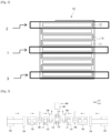
- an apparatus 100 for manufacturing an electrode assembly includes a stack table 110; a separator supply unit 120 for supplying a separator 14; a first electrode supply unit 130 for supplying a first electrode 11; a second electrode supply unit 140 for supplying a second electrode 12; a first electrode stack unit 150 for stacking the first electrode 11 on the stack table 110; a second electrode stack unit 160 for stacking the second electrode 12 on the stack table 110; and a press unit 180 for bonding the first electrode 11, the separator 14, and the second electrode 12 to each other.
- the apparatus 100 for manufacturing the electrode assembly may include a holding mechanism 170 for fixing the stack (comprising the first electrode(s) 11, the second electrode(s) 12, and the separator 14) to the stack table 110 as the stack is being assembled.
- the separator supply unit 120 may have a passage through which the separator 14 passes towards the stack table 110.
- the separator supply unit 120 may include a separator heating unit 121 defining the passage through which the separator 14 passes towards the stack table 110.
- the separator heating unit 121 may include a pair of bodies 121a, each of which may be in the form of a square block, and the bodies 121a may be spaced apart by a distance defining one of the dimensions of the passage through which the separator 14 passes. At least one or both of the bodies 121a may further include a separator heater 121b for heating the respective body 121a, and thereby transferring heat to the separator 14.
- the separator supply unit 120 may further include a separator roll 122 on which the separator 14 is wound.
- the separator 14 wound on the separator roll 122 may be gradually unwound and pass through the formed passage to be supplied to the stack table 110.
- the second electrode supply unit 140 may include a second electrode seating table 141 on which the second electrode 12 is seated before being stacked on the stack table 110 by the second electrode stack unit 160.
- the second electrode supply unit 140 may further include a second electrode roll 143 on which the second electrode 12 is wound in the form of a sheet, a second cutter 144 for cutting the second electrode 12 at regular intervals to form the second electrode 12 of a predetermined size when the second electrode 12 is unwound and supplied from the second electrode roll 143, a second conveyor belt 145 for moving the second electrode 121 cut by the second cutter 144, and a second electrode supply head 146 for picking up (e.g., via vacuum suction) the second electrode 12 transferred by the second conveyor belt 145 and seating the second electrode on the second electrode seating table 141.
- the first electrode stack unit 150 may be structured to stack the first electrode 11 on the stack table 110.
- the first electrode stack unit 150 may include a first suction head 151 and a first moving unit 153.
- the first suction head 151 may pick up the first electrode 11 seated on the first electrode seating table 131 via vacuum suction through one or more vacuum suction ports (not shown) formed on a bottom surface of the first suction head 150, and then the first moving unit 153 may move the first suction head 151 to the stack table 110 so as to allow the first suction head 151 to stack the first electrode 11 on the stack table 110.
- the second electrode stack unit 160 may also be structured to stack the second electrode 12 on the stack table 110.
- the second electrode stack unit 160 may have the same structure as that of the foregoing first electrode stack unit 150.
- the second electrode stack unit 160 may include a second suction head 161 and a second moving unit 163.
- the second suction head 161 may pick up the second electrode 12 seated on the second electrode seating table 141 via vacuum suction.
- the second moving unit 163 may then move the second suction head 161 to the stack table 110 so as to allow the second suction head 161 to stack the second electrode 12 on the stack table 110.
- the stack table 110 may be rotatable so as to rotate between positions facing the first electrode stack unit 150 and the second electrode stack unit 160.
- the holding mechanism 170 may hold the stack being assembled (comprising the first electrode 11, the second electrode 12, and the separator 14) in order to secure the position of the stack relative to the stack table 110.
- the holding mechanism 170 may apply downward pressure to the upper surface of the stack to press it towards the stack table 110.
- the holding mechanism 170 may include, for example, a first holder 171 and a second holder 172 to fix opposing sides of the first electrode 11 or the second electrode 12.
- the holders 171, 172 may each be in the form of one or more clamps or other clamping mechanisms.
- the first electrode 11 is supplied from the first electrode supply unit 130 to the first electrode stack unit 150, the first electrode stack unit 150 stacks the first electrode 11 on the upper surface of the separator 14 stacked on the stack table 110.
- the holding mechanism 170 then presses down on the upper surface of the first electrode 11 to secure the position of the first electrode 11 on the stack table 110.
- the stack table 110 is rotated in the direction of the second electrode stack unit 160 while the separator 14 is continuously supplied so as to cover the upper surface of the first electrode 11.
- the second electrode 12 is supplied from the second electrode supply unit 140 and is stacked by the second electrode stack unit 160 on a portion of the separator 14 where the separator 14 covers the upper surface of the first electrode 11.
- the holding mechanism 170 releases the upper surface of the first electrode 11 and then presses down on the upper surface of the second electrode 12 to secure the position of the stack S being built vis-a-vis the stack table 110. Thereafter, by repeating the process of stacking the first electrode 11 and the second electrode 12, the stack S in which the separator 14 is zig-zag-folded and positioned between each of the successive first and second electrodes 11, 12 may be formed.
- the electrode assembly may undergo one or more heat press operations.
- the electrode assembly may be moved to the press unit 180, which applies heat and pressure to the stack by advancing heated pressing blocks 181 and 182 towards one another with the stack positioned therebetween.
- the components of the stack i.e., the electrodes and separator
- the components of the stack are thermally bonded to one another, so as to desirably prevent the completed electrode assembly from falling apart or the components of the electrode assembly from shifting their positions within the stack.
- the heat press operations applied to the electrode assembly may include a primary heat press operation and a secondary heat press operation.
- the primary heat press relates to an operation after the first electrode(s) and the second electrode(s) are alternately stacked between the folded separators to define a stack, where the stack is gripped with a gripper, and then the stack is heated and pressed.
- the secondary heat press operation relates to an operation after the primary heat press operation, in which the gripping of the stack by the gripper is ceased and the stack is once more heated and pressed.
- the method may first include a stack process of assembling a stack (stack cell) on a stack table by alternately stacking the first electrode and the second electrode on the separator, where the separator is continuously supplied and sequentially folded over a previously-stacked one of the first and second electrodes before a subsequent one of the first and second electrodes is stacked.
- the stack may be moved away from the stack table.
- the separator is pulled, and, after the separator is pulled for a predetermined length, the separator is cut. Thereafter, the predetermined length of he cut end of the separator is wound around the stack cell.
- the movement of the stack away from the stack table may be accomplished by the gripper, which is desirably a movable component that can grip the stack on the stack table and then move the stack to the press unit 180, where the heat press operations are performed.
- the primary heat press operation is then performed in a state in which the wound stack cell is gripped with the gripper. After the primary heat press operation is completed, the grip of the stack cell by the gripper is released. After the gripper is removed, the secondary heat press operation is performed. When the secondary heat press operation is completed, the finished electrode assembly may be complete.
- the components of the electrode assembly may not be properly adhered together, which can result in the electrode assembly falling apart or the components of the electrode assembly shifting their positions within the assembly, particularly when the electrode assembly is moved before being inserted into a battery case.
- a problem may also occur in which the air permeability of the separator is excessively high.
- an electrode assembly may be manufactured without the need to individually heat and/or press each level of the electrode assembly (i.e., heating and/or pressing each electrode and separator pair at each step of the process) in order to bond the components together.
- Such individual heat pressing at each level can detrimentally cause the effects of the heat and/or pressure to accumulate in the lower separators in the stack, since the already-stacked layers will experience the heat and/or pressure of each application. That can negatively impact such portions of separator by, for example, reducing porosity (and air permeability).
- the present invention allows the entire electrode assembly to be simultaneously bonded, which improves uniformity, among other things. It is thus possible to simultaneously achieve both an appropriate level of adhesive force between the electrodes and also achieve a separator having an appropriate amount of air permeability, all while minimizing damage to the unit electrode.
- the "air permeability" of the electrode assembly refers to the air permeability of the separator component of the electrode assembly.
- air permeability means air permeability of all separators comprising the electrode assembly, where the air permeability of each separator may be independently the same or different.
- the separator desirably has an air permeability in a range from 40 sec/100 ml to 120 sec/100 ml.
- the electrode assembly according to the present invention preferably has higher air permeability than electrode assemblies in the related art, thereby increasing the safety of the electrode assembly.
- the upper surface air permeability and the lower surface air permeability of the electrode assembly according to the present invention are in a range from 80 sec/100 ml to 120 sec/100 ml.
- a Gurley type Densometer (No. 158) manufactured by Toyoseiki may be used according to the JIS Gurley measurement method of the Japanese industrial standard. That is, the air permeability of the separator may be obtained by measuring the time it takes for 100 ml (or 100 cc) of air to pass through the separator of 1 square inch, equivalent to 6.45 square centimeters, under a pressure of 0.05 MPa at room temperature (i.e., 20°C to 25°C).
- the middle air permeability of the electrode assembly may be in a range from 70 sec/100 ml to 85 sec/100 ml, preferably from 75 sec/100 ml to 85 sec/100 ml.
- the upper surface air permeability of the electrode assembly is in a range from 80 sec/100 ml to 120 sec/100 ml, preferably from 80 sec/100 ml to 110 sec/110 ml, more preferably from 80 sec/100 ml to 100 sec/100 ml.
- the lower surface air permeability of the electrode assembly is in a range from 80 sec/100 ml to 120 sec/100 ml, preferably from 80 sec/100 ml to 110 sec/110 ml, more preferably from 80 sec/100 ml to 100 sec/100 ml.
- the lower surface air permeability may be less than or equal to the upper surface air permeability.
- the middle air permeability may be less than or equal to the lower surface air permeability.
- Equation 1 the magnitude of the upper surface air permeability, the lower surface air permeability, and the middle air permeability may satisfy Equation 1 below.
- Equation 1 The values of air permeability in Equation 1 relate to the air permeability of the separators in the electrode assembly after the completion of the heating and pressing steps.
- the adhesive force between the separator and the electrodes at any of the positions in the electrode assembly may be in a range from 5 gf/20 mm to 75 gf/20 mm (0.049N/20mm to 0.735N/20mm, wherein 1gf is equivalent to 0.0098N).
- a method for measuring adhesive force of the separator is according to the testing method set forth in ASTM D6862.
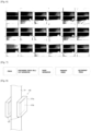
- samples of the lower portion, the middle portion, and the upper portion of the electrode assembly may be separated from the stack.
- Such samples may include a positive electrode and a separator or a negative electrode and a separator.
- the samples which may have a width of 55 mm and a length of 20 mm, are each adhered to a respective slide glass with the electrode being positioned on the adhesive surface of the slide glass.
- the samples are then each tested by performing a 90° peel test at a speed of 100 mm/min pursuant to the testing method set forth in ASTM-D6862.
- an edge of the separator is pulled upwardly at 90° relative to the slide glass at a speed of 100 mm/min so as to peel the separator away from the electrode along the width direction of the sample (i.e., peeling from 0 mm to 55 mm).
- the middle adhesive force of the electrode assembly may be in a range from 5 gf/20 mm to 35 gf/20 mm, preferably from 5 gf/20 mm to 15 gf/20 mm.
- the lower surface adhesive force of the electrode assembly may be in a range from 5 gf/20 mm to 75 gf/20 mm, preferably from 9 gf/20 mm to 30 gf/20 mm.
- the adhesive force between the positive electrode and the separator and the adhesive force between the negative electrode and the separator may be the same as or may be different from each other.
- a deviation between the middle adhesive force of the electrode assembly and either the upper surface adhesive force or the lower surface adhesive force of the electrode assembly may be in a range from 10 gf/20 mm to 35 gf/20 mm, preferably from 10 gf/20 mm to 20 gf/20 mm.
- the air permeability and adhesive force conditions described above may preferably make cleaning and process handling easy, and it may also make wetting of the separator by the electrolyte easier, so that an electrode assembly having uniform performance may be manufactured.
- side-effects such as lithium (Li) precipitation in the electrode assembly and non-charging of the electrode assembly, may be prevented.
- a thickness deviation of the electrodes of the electrode assembly may be in a range from 0.013 mm to 0.035 mm.
- the positive electrode and the negative electrode were supplied after being cut from a positive electrode sheet and a negative electrode sheet, respectively, and the separator was supplied in the form of an elongated separator sheet. Thereafter, the supplied separator was folded while rotating the stack table and stacking the positive electrodes and the negative electrode as described above. A holding mechanism was used to press down on and stabilize the stack, which resulted in a stack including 39 electrodes.
- a primary heat press operation was performed by gripping the stack with the gripper and pressing for 15 seconds while heating the stack under a temperature condition of 70°C and a pressure condition of 1.91 MPa.
- the above-described disclosure may be applied.
- Electrode assemblies of Comparative Examples 1 to 7 were manufactured in the same manner as in Example 1, except that the primary heat press operation was performed under the temperature conditions, pressure conditions, and press time represented in Table 2 below, and the secondary heat press operation was not performed.
- Table 2 Primary heat press Temperature condition (°C) Pressure condition Press time (s) Press area Tonf MPa Comparative Example 1 70 6 1.91 15 Comparative Example 2 80 6 1.91 15 Comparative Example 3 80 8 2.54 8 Comparative Example 4 80 8 2.54 15 Comparative Example 5 90 6 1.91 15 Comparative Example 6 90 8 2.54 8 Comparative 90 8 2.54 5
- Example 7 Secondary heat press (not performed) Temperature condition (°C) Pressure condition Press time (s) Press area (554.1 cm 2 ) Tonf MPa Comparative Example 1 - - - - Comparative Example 2 - - - - Comparative Example 3 - - - - Comparative Example 4 - - - - - Comparative Example 5 - - - - Comparative Example 6 - - -
- the separators were cut to prepare separator samples having a size of 5 cm X 5 cm (width X length). After that, the separator samples were washed with acetone.
- Air permeability of Examples 1 to 3 and Comparative Example 1 were measured by measuring the time it took for 100 ml (or 100 cc) of air to pass through the separator of 1 square inch at room temperature and under the pressure condition of 0.05 MPa by using a Gurley type Densometer (No. 158) from Toyoseiki in accordance with the JIS Gurley measurement method of the Japanese industrial standard.
- the upper surface air permeability and the lower surface air permeability of the electrode assembly according to the present invention were each independently 80 sec/100 ml or more. Further, it was confirmed that the upper surface air permeability and the lower surface air permeability of the electrode assembly according to the present invention did not exceed 120 sec/100 ml. That is, it could be confirmed that the electrode assembly according to the present invention has an appropriate level of air permeability for use as an electrode assembly.
- the electrode assembly of the present invention has excellent adhesive force and, at the same time, has a withstand voltage suitable for use as an electrode assembly. In that regard, a withstand voltage of 1.8 kV or less was confirmed.
- the electrode assembly of the present invention was manufactured by the manufacturing method including both the primary and secondary heat press operations.
- the electrode assembly of the present invention was manufactured by the manufacturing method including both the primary and secondary heat press operations.
- the electrode assembly according to the present invention has an appropriate withstand voltage while also having excellent stability and adhesive force, and it is possible to prevent side-effects, such as lithium (Li) precipitation in the electrode assembly and non-charging of the electrode assembly.
- the electrode assembly of the present invention was manufactured by the manufacturing method including both the primary and secondary heat press operations.
Landscapes
- Chemical & Material Sciences (AREA)
- Chemical Kinetics & Catalysis (AREA)
- Electrochemistry (AREA)
- General Chemical & Material Sciences (AREA)
- Engineering & Computer Science (AREA)
- Manufacturing & Machinery (AREA)
- Secondary Cells (AREA)
- Cell Separators (AREA)
- Battery Electrode And Active Subsutance (AREA)
- Hybrid Cells (AREA)
- Inert Electrodes (AREA)
Applications Claiming Priority (5)
| Application Number | Priority Date | Filing Date | Title |
|---|---|---|---|
| KR20210090596 | 2021-07-09 | ||
| KR20210090598 | 2021-07-09 | ||
| KR20210090592 | 2021-07-09 | ||
| KR20210090597 | 2021-07-09 | ||
| PCT/KR2022/010004 WO2023282717A1 (en) | 2021-07-09 | 2022-07-08 | Electrode assembly |
Publications (3)
| Publication Number | Publication Date |
|---|---|
| EP4252301A1 EP4252301A1 (en) | 2023-10-04 |
| EP4252301A4 EP4252301A4 (en) | 2024-10-23 |
| EP4252301B1 true EP4252301B1 (en) | 2025-07-02 |
Family
ID=84801822
Family Applications (4)
| Application Number | Title | Priority Date | Filing Date |
|---|---|---|---|
| EP22838068.9A Active EP4252301B1 (en) | 2021-07-09 | 2022-07-08 | Electrode assembly |
| EP22838069.7A Active EP4264721B1 (en) | 2021-07-09 | 2022-07-08 | Manufacturing method for electrode assembly and electrode assembly manufacturing equipment |
| EP22838067.1A Active EP4248514B1 (en) | 2021-07-09 | 2022-07-08 | Electrode assembly |
| EP25158706.9A Pending EP4535545A3 (en) | 2021-07-09 | 2022-07-08 | Manufacturing method for electrode assembly and electrode assembly manufacturing equipment |
Family Applications After (3)
| Application Number | Title | Priority Date | Filing Date |
|---|---|---|---|
| EP22838069.7A Active EP4264721B1 (en) | 2021-07-09 | 2022-07-08 | Manufacturing method for electrode assembly and electrode assembly manufacturing equipment |
| EP22838067.1A Active EP4248514B1 (en) | 2021-07-09 | 2022-07-08 | Electrode assembly |
| EP25158706.9A Pending EP4535545A3 (en) | 2021-07-09 | 2022-07-08 | Manufacturing method for electrode assembly and electrode assembly manufacturing equipment |
Country Status (7)
| Country | Link |
|---|---|
| EP (4) | EP4252301B1 (pl) |
| JP (4) | JP7648041B2 (pl) |
| KR (5) | KR102570167B1 (pl) |
| ES (3) | ES3027939T3 (pl) |
| HU (3) | HUE072267T2 (pl) |
| PL (3) | PL4252301T3 (pl) |
| WO (3) | WO2023282717A1 (pl) |
Families Citing this family (1)
| Publication number | Priority date | Publication date | Assignee | Title |
|---|---|---|---|---|
| WO2026079717A1 (ko) * | 2024-10-10 | 2026-04-16 | 주식회사 엘지에너지솔루션 | 분리막, 이의 제조방법 및 이를 포함하는 전기화학소자 |
Family Cites Families (37)
| Publication number | Priority date | Publication date | Assignee | Title |
|---|---|---|---|---|
| TW499766B (en) * | 2000-03-29 | 2002-08-21 | Elite Ionergy Co Ltd | Battery manufacturing method |
| JP2005243455A (ja) | 2004-02-26 | 2005-09-08 | Tdk Corp | 電気化学デバイス |
| JP2006032246A (ja) | 2004-07-21 | 2006-02-02 | Sanyo Electric Co Ltd | 非水電解質電池用セパレータ及び非水電解質電池 |
| JP5135678B2 (ja) * | 2005-11-24 | 2013-02-06 | 日産自動車株式会社 | 電池構造体、組電池、およびこれらを搭載した車両 |
| JP4284341B2 (ja) * | 2006-07-25 | 2009-06-24 | 株式会社東芝 | 非水電解質電池、自動車、アシスト自転車、二輪車、充電式掃除機及び電池パック |
| JP5017995B2 (ja) * | 2006-10-02 | 2012-09-05 | パナソニック株式会社 | リチウム二次電池用極板の製造方法、その製造法を用いたリチウム二次電池用極板とリチウム二次電池 |
| JP4964820B2 (ja) * | 2008-04-21 | 2012-07-04 | シーケーディ株式会社 | 巻回素子のプレス装置 |
| JP5259453B2 (ja) * | 2009-02-25 | 2013-08-07 | 富士重工業株式会社 | 蓄電デバイスおよびその製造方法 |
| JP2013149477A (ja) * | 2012-01-19 | 2013-08-01 | Hitachi Maxell Ltd | 非水二次電池の製造方法 |
| KR20130132230A (ko) | 2012-05-25 | 2013-12-04 | 주식회사 엘지화학 | 단차를 갖는 전극 조립체 및 이를 포함하는 전지셀, 전지팩 및 디바이스 |
| WO2014017651A1 (ja) * | 2012-07-26 | 2014-01-30 | 旭化成イーマテリアルズ株式会社 | 蓄電デバイス用セパレータ、積層体、及び多孔膜 |
| KR101704759B1 (ko) * | 2012-11-12 | 2017-02-08 | 주식회사 엘지화학 | 스택/폴딩형 전극조립체 및 그를 포함하는 전기화학소자 |
| KR101602908B1 (ko) * | 2012-11-20 | 2016-03-11 | 주식회사 엘지화학 | 전극조립체 및 그를 포함하는 전기화학소자 |
| KR101816763B1 (ko) * | 2013-05-08 | 2018-01-09 | 주식회사 엘지화학 | 절연층을 포함한 전극 구조체, 그 제조방법 및 상기 전극을 포함하는 전기화학소자 |
| KR101587322B1 (ko) * | 2013-08-05 | 2016-01-20 | 주식회사 엘지화학 | 전극조립체용 사행보정장치 |
| KR20150022264A (ko) * | 2013-08-22 | 2015-03-04 | 삼성에스디아이 주식회사 | 리튬 이차 전지의 제조방법 및 상기 제조방법에 의해 제조된 리튬 이차 전지 |
| KR101595621B1 (ko) * | 2013-09-27 | 2016-02-18 | 주식회사 엘지화학 | 전극조립체 제조방법 |
| ITTO20130936A1 (it) | 2013-11-19 | 2015-05-20 | Cte Sistemi Srl | Gruppo di misura per misurare il raggio di curvatura e l'avanzamento in una macchina curvatrice, in particolare in una macchina curvatrice per la curvatura di conduttori per bobine superconduttive |
| KR101750239B1 (ko) | 2014-11-06 | 2017-06-23 | 주식회사 엘지화학 | Srs 분리막을 포함하는 전극조립체 |
| KR102604599B1 (ko) * | 2015-04-02 | 2023-11-22 | 에스케이이노베이션 주식회사 | 리튬 이차전지용 복합 분리막 및 이의 제조방법 |
| CN107851841B (zh) * | 2015-07-30 | 2020-12-11 | 富士胶片株式会社 | 固体电解质组合物、全固态二次电池及其电极片以及全固态二次电池及其电极片的制造方法 |
| KR102279304B1 (ko) | 2015-10-19 | 2021-07-21 | 삼성전기주식회사 | 촬상 광학계 |
| KR102016645B1 (ko) * | 2016-07-08 | 2019-08-30 | 주식회사 엘지화학 | 전극 조립체 및 그의 제조 방법 |
| KR102065131B1 (ko) * | 2016-10-05 | 2020-03-02 | 주식회사 엘지화학 | 전극 조립체 및 이의 제조 방법 |
| WO2018116295A1 (en) * | 2016-12-19 | 2018-06-28 | StoreDot Ltd. | Layer preparation, treatment, transfer and lamination in cell stack assembly processes for lithium ion batteries |
| KR102256438B1 (ko) * | 2017-03-20 | 2021-06-03 | 주식회사 엘지화학 | 2종의 분리막을 포함하는 스택-폴딩형 전극조립체 |
| US10490843B2 (en) * | 2017-04-10 | 2019-11-26 | Nano And Advanced Materials Institute Limited | Flexible battery with 180 degree operational bend radius |
| CN108390101B (zh) * | 2018-01-03 | 2020-06-23 | 多氟多新能源科技有限公司 | 一种锂离子电池电芯及其制备方法、锂离子电池 |
| KR102265741B1 (ko) * | 2018-03-21 | 2021-06-16 | (주)엘지에너지솔루션 | 리튬 이차 전지의 제조방법 및 이에 의해 제조된 리튬 이차 전지 |
| PL3780171T3 (pl) * | 2018-03-26 | 2023-11-27 | Zeon Corporation | Sposób wytwarzania warstwowego korpusu niewodnej baterii akumulatorowej i sposób wytwarzania niewodnej baterii akumulatorowej |
| JP7170424B2 (ja) * | 2018-05-16 | 2022-11-14 | 旭化成株式会社 | 微多孔膜の製造方法およびそれを用いた微多孔膜 |
| KR102619206B1 (ko) | 2018-07-15 | 2023-12-28 | 신주연 | 음료 조성물 |
| KR102578215B1 (ko) * | 2018-08-27 | 2023-09-14 | 주식회사 엘지에너지솔루션 | 전극 조립체 제조장치 |
| KR102578204B1 (ko) | 2018-08-27 | 2023-09-14 | 주식회사 엘지에너지솔루션 | 전극 조립체 제조장치 |
| KR102761334B1 (ko) * | 2019-01-30 | 2025-02-04 | 주식회사 엘지에너지솔루션 | 전극 조립체와 이차전지의 제조 방법 및 제조 장치 |
| JP7169908B2 (ja) * | 2019-03-07 | 2022-11-11 | 宇部マクセル京都株式会社 | セパレータ |
| KR102278800B1 (ko) | 2019-05-27 | 2021-07-19 | 주식회사 제윤 | 탄창형 약 포지 토출 장치 및 이를 이용한 복약 관리 시스템 |
-
2022
- 2022-07-08 EP EP22838068.9A patent/EP4252301B1/en active Active
- 2022-07-08 WO PCT/KR2022/010004 patent/WO2023282717A1/en not_active Ceased
- 2022-07-08 JP JP2023536801A patent/JP7648041B2/ja active Active
- 2022-07-08 ES ES22838069T patent/ES3027939T3/es active Active
- 2022-07-08 WO PCT/KR2022/010003 patent/WO2023282716A1/en not_active Ceased
- 2022-07-08 HU HUE22838068A patent/HUE072267T2/hu unknown
- 2022-07-08 PL PL22838068.9T patent/PL4252301T3/pl unknown
- 2022-07-08 JP JP2023540990A patent/JP7667283B2/ja active Active
- 2022-07-08 KR KR1020220084657A patent/KR102570167B1/ko active Active
- 2022-07-08 EP EP22838069.7A patent/EP4264721B1/en active Active
- 2022-07-08 ES ES22838067T patent/ES3047879T3/es active Active
- 2022-07-08 ES ES22838068T patent/ES3036384T3/es active Active
- 2022-07-08 KR KR1020220084647A patent/KR102549232B1/ko active Active
- 2022-07-08 PL PL22838067.1T patent/PL4248514T3/pl unknown
- 2022-07-08 WO PCT/KR2022/010005 patent/WO2023282718A1/en not_active Ceased
- 2022-07-08 EP EP22838067.1A patent/EP4248514B1/en active Active
- 2022-07-08 HU HUE22838067A patent/HUE073463T2/hu unknown
- 2022-07-08 PL PL22838069.7T patent/PL4264721T3/pl unknown
- 2022-07-08 EP EP25158706.9A patent/EP4535545A3/en active Pending
- 2022-07-08 KR KR1020220084653A patent/KR102540600B1/ko active Active
- 2022-07-08 JP JP2023537459A patent/JP2024502559A/ja active Pending
- 2022-07-08 HU HUE22838069A patent/HUE071264T2/hu unknown
-
2023
- 2023-08-18 KR KR1020230108117A patent/KR102608542B1/ko active Active
- 2023-11-23 KR KR1020230164329A patent/KR102710171B1/ko active Active
-
2025
- 2025-04-08 JP JP2025063870A patent/JP2025108514A/ja active Pending
Also Published As
Similar Documents
| Publication | Publication Date | Title |
|---|---|---|
| US12272839B2 (en) | Electrode assembly | |
| US11799173B2 (en) | Secondary battery and manufacturing method thereof | |
| KR102642436B1 (ko) | 전극 조립체 | |
| EP4252301B1 (en) | Electrode assembly | |
| EP4322273B1 (en) | Electrode assembly and manufacturing method therefor | |
| CN116745949A (zh) | 电极组件 | |
| CN116724431A (zh) | 电极组件 | |
| US20250062493A1 (en) | Manufacturing Method for Electrode Assembly and Electrode Assembly Manufacturing Equipment |
Legal Events
| Date | Code | Title | Description |
|---|---|---|---|
| STAA | Information on the status of an ep patent application or granted ep patent |
Free format text: STATUS: THE INTERNATIONAL PUBLICATION HAS BEEN MADE |
|
| PUAI | Public reference made under article 153(3) epc to a published international application that has entered the european phase |
Free format text: ORIGINAL CODE: 0009012 |
|
| STAA | Information on the status of an ep patent application or granted ep patent |
Free format text: STATUS: REQUEST FOR EXAMINATION WAS MADE |
|
| 17P | Request for examination filed |
Effective date: 20230629 |
|
| AK | Designated contracting states |
Kind code of ref document: A1 Designated state(s): AL AT BE BG CH CY CZ DE DK EE ES FI FR GB GR HR HU IE IS IT LI LT LU LV MC MK MT NL NO PL PT RO RS SE SI SK SM TR |
|
| DAV | Request for validation of the european patent (deleted) | ||
| DAX | Request for extension of the european patent (deleted) | ||
| A4 | Supplementary search report drawn up and despatched |
Effective date: 20240920 |
|
| RIC1 | Information provided on ipc code assigned before grant |
Ipc: H01M 50/466 20210101ALI20240917BHEP Ipc: H01M 10/052 20100101ALI20240917BHEP Ipc: H01M 10/0583 20100101ALI20240917BHEP Ipc: H01M 50/46 20210101ALI20240917BHEP Ipc: H01M 50/489 20210101ALI20240917BHEP Ipc: H01M 10/04 20060101AFI20240917BHEP |
|
| GRAP | Despatch of communication of intention to grant a patent |
Free format text: ORIGINAL CODE: EPIDOSNIGR1 |
|
| STAA | Information on the status of an ep patent application or granted ep patent |
Free format text: STATUS: GRANT OF PATENT IS INTENDED |
|
| GRAJ | Information related to disapproval of communication of intention to grant by the applicant or resumption of examination proceedings by the epo deleted |
Free format text: ORIGINAL CODE: EPIDOSDIGR1 |
|
| STAA | Information on the status of an ep patent application or granted ep patent |
Free format text: STATUS: REQUEST FOR EXAMINATION WAS MADE |
|
| INTG | Intention to grant announced |
Effective date: 20250227 |
|
| GRAP | Despatch of communication of intention to grant a patent |
Free format text: ORIGINAL CODE: EPIDOSNIGR1 |
|
| STAA | Information on the status of an ep patent application or granted ep patent |
Free format text: STATUS: GRANT OF PATENT IS INTENDED |
|
| INTC | Intention to grant announced (deleted) | ||
| P01 | Opt-out of the competence of the unified patent court (upc) registered |
Free format text: CASE NUMBER: APP_13990/2025 Effective date: 20250321 |
|
| INTG | Intention to grant announced |
Effective date: 20250408 |
|
| GRAS | Grant fee paid |
Free format text: ORIGINAL CODE: EPIDOSNIGR3 |
|
| GRAA | (expected) grant |
Free format text: ORIGINAL CODE: 0009210 |
|
| STAA | Information on the status of an ep patent application or granted ep patent |
Free format text: STATUS: THE PATENT HAS BEEN GRANTED |
|
| AK | Designated contracting states |
Kind code of ref document: B1 Designated state(s): AL AT BE BG CH CY CZ DE DK EE ES FI FR GB GR HR HU IE IS IT LI LT LU LV MC MK MT NL NO PL PT RO RS SE SI SK SM TR |
|
| REG | Reference to a national code |
Ref country code: GB Ref legal event code: FG4D |
|
| REG | Reference to a national code |
Ref country code: CH Ref legal event code: EP |
|
| REG | Reference to a national code |
Ref country code: DE Ref legal event code: R096 Ref document number: 602022017089 Country of ref document: DE |
|
| REG | Reference to a national code |
Ref country code: IE Ref legal event code: FG4D |
|
| PGFP | Annual fee paid to national office [announced via postgrant information from national office to epo] |
Ref country code: NL Payment date: 20250722 Year of fee payment: 4 |
|
| REG | Reference to a national code |
Ref country code: NL Ref legal event code: FP |
|
| REG | Reference to a national code |
Ref country code: SE Ref legal event code: TRGR |
|
| REG | Reference to a national code |
Ref country code: ES Ref legal event code: FG2A Ref document number: 3036384 Country of ref document: ES Kind code of ref document: T3 Effective date: 20250918 |
|
| PGFP | Annual fee paid to national office [announced via postgrant information from national office to epo] |
Ref country code: ES Payment date: 20250822 Year of fee payment: 4 |
|
| PGFP | Annual fee paid to national office [announced via postgrant information from national office to epo] |
Ref country code: DE Payment date: 20250721 Year of fee payment: 4 |
|
| PGFP | Annual fee paid to national office [announced via postgrant information from national office to epo] |
Ref country code: TR Payment date: 20250730 Year of fee payment: 4 Ref country code: PL Payment date: 20250714 Year of fee payment: 4 Ref country code: IT Payment date: 20250731 Year of fee payment: 4 |
|
| PGFP | Annual fee paid to national office [announced via postgrant information from national office to epo] |
Ref country code: BE Payment date: 20250722 Year of fee payment: 4 Ref country code: HU Payment date: 20250929 Year of fee payment: 4 |
|
| PGFP | Annual fee paid to national office [announced via postgrant information from national office to epo] |
Ref country code: AT Payment date: 20251020 Year of fee payment: 4 Ref country code: FR Payment date: 20250725 Year of fee payment: 4 |
|
| PGFP | Annual fee paid to national office [announced via postgrant information from national office to epo] |
Ref country code: SE Payment date: 20250722 Year of fee payment: 4 |
|
| REG | Reference to a national code |
Ref country code: HU Ref legal event code: AG4A Ref document number: E072267 Country of ref document: HU |
|
| PG25 | Lapsed in a contracting state [announced via postgrant information from national office to epo] |
Ref country code: PT Free format text: LAPSE BECAUSE OF FAILURE TO SUBMIT A TRANSLATION OF THE DESCRIPTION OR TO PAY THE FEE WITHIN THE PRESCRIBED TIME-LIMIT Effective date: 20251103 |
|
| REG | Reference to a national code |
Ref country code: AT Ref legal event code: MK05 Ref document number: 1810306 Country of ref document: AT Kind code of ref document: T Effective date: 20250702 |
|
| PG25 | Lapsed in a contracting state [announced via postgrant information from national office to epo] |
Ref country code: IS Free format text: LAPSE BECAUSE OF FAILURE TO SUBMIT A TRANSLATION OF THE DESCRIPTION OR TO PAY THE FEE WITHIN THE PRESCRIBED TIME-LIMIT Effective date: 20251102 |
|
| PG25 | Lapsed in a contracting state [announced via postgrant information from national office to epo] |
Ref country code: NO Free format text: LAPSE BECAUSE OF FAILURE TO SUBMIT A TRANSLATION OF THE DESCRIPTION OR TO PAY THE FEE WITHIN THE PRESCRIBED TIME-LIMIT Effective date: 20251002 |
|
| REG | Reference to a national code |
Ref country code: LT Ref legal event code: MG9D |
|
| PG25 | Lapsed in a contracting state [announced via postgrant information from national office to epo] |
Ref country code: AT Free format text: LAPSE BECAUSE OF FAILURE TO SUBMIT A TRANSLATION OF THE DESCRIPTION OR TO PAY THE FEE WITHIN THE PRESCRIBED TIME-LIMIT Effective date: 20250702 |
|
| PG25 | Lapsed in a contracting state [announced via postgrant information from national office to epo] |
Ref country code: FI Free format text: LAPSE BECAUSE OF FAILURE TO SUBMIT A TRANSLATION OF THE DESCRIPTION OR TO PAY THE FEE WITHIN THE PRESCRIBED TIME-LIMIT Effective date: 20250702 |
|
| PG25 | Lapsed in a contracting state [announced via postgrant information from national office to epo] |
Ref country code: HR Free format text: LAPSE BECAUSE OF FAILURE TO SUBMIT A TRANSLATION OF THE DESCRIPTION OR TO PAY THE FEE WITHIN THE PRESCRIBED TIME-LIMIT Effective date: 20250702 |
|
| PG25 | Lapsed in a contracting state [announced via postgrant information from national office to epo] |
Ref country code: GR Free format text: LAPSE BECAUSE OF FAILURE TO SUBMIT A TRANSLATION OF THE DESCRIPTION OR TO PAY THE FEE WITHIN THE PRESCRIBED TIME-LIMIT Effective date: 20251003 |
|
| PG25 | Lapsed in a contracting state [announced via postgrant information from national office to epo] |
Ref country code: CZ Free format text: LAPSE BECAUSE OF FAILURE TO SUBMIT A TRANSLATION OF THE DESCRIPTION OR TO PAY THE FEE WITHIN THE PRESCRIBED TIME-LIMIT Effective date: 20250702 |
|
| PG25 | Lapsed in a contracting state [announced via postgrant information from national office to epo] |
Ref country code: LV Free format text: LAPSE BECAUSE OF FAILURE TO SUBMIT A TRANSLATION OF THE DESCRIPTION OR TO PAY THE FEE WITHIN THE PRESCRIBED TIME-LIMIT Effective date: 20250702 |
|
| PG25 | Lapsed in a contracting state [announced via postgrant information from national office to epo] |
Ref country code: BG Free format text: LAPSE BECAUSE OF FAILURE TO SUBMIT A TRANSLATION OF THE DESCRIPTION OR TO PAY THE FEE WITHIN THE PRESCRIBED TIME-LIMIT Effective date: 20250702 |
|
| PG25 | Lapsed in a contracting state [announced via postgrant information from national office to epo] |
Ref country code: RS Free format text: LAPSE BECAUSE OF FAILURE TO SUBMIT A TRANSLATION OF THE DESCRIPTION OR TO PAY THE FEE WITHIN THE PRESCRIBED TIME-LIMIT Effective date: 20251002 |
|
| REG | Reference to a national code |
Ref country code: CH Ref legal event code: H13 Free format text: ST27 STATUS EVENT CODE: U-0-0-H10-H13 (AS PROVIDED BY THE NATIONAL OFFICE) Effective date: 20260224 |
|
| PG25 | Lapsed in a contracting state [announced via postgrant information from national office to epo] |
Ref country code: RO Free format text: LAPSE BECAUSE OF FAILURE TO SUBMIT A TRANSLATION OF THE DESCRIPTION OR TO PAY THE FEE WITHIN THE PRESCRIBED TIME-LIMIT Effective date: 20250702 Ref country code: LU Free format text: LAPSE BECAUSE OF NON-PAYMENT OF DUE FEES Effective date: 20250708 |
|
| PG25 | Lapsed in a contracting state [announced via postgrant information from national office to epo] |
Ref country code: SM Free format text: LAPSE BECAUSE OF FAILURE TO SUBMIT A TRANSLATION OF THE DESCRIPTION OR TO PAY THE FEE WITHIN THE PRESCRIBED TIME-LIMIT Effective date: 20250702 |
|
| PG25 | Lapsed in a contracting state [announced via postgrant information from national office to epo] |
Ref country code: DK Free format text: LAPSE BECAUSE OF FAILURE TO SUBMIT A TRANSLATION OF THE DESCRIPTION OR TO PAY THE FEE WITHIN THE PRESCRIBED TIME-LIMIT Effective date: 20250702 |