EP4249657B1 - Haarpflanzgerät - Google Patents
Haarpflanzgerät Download PDFInfo
- Publication number
- EP4249657B1 EP4249657B1 EP23162856.1A EP23162856A EP4249657B1 EP 4249657 B1 EP4249657 B1 EP 4249657B1 EP 23162856 A EP23162856 A EP 23162856A EP 4249657 B1 EP4249657 B1 EP 4249657B1
- Authority
- EP
- European Patent Office
- Prior art keywords
- base material
- hair
- clamp
- planting
- axis
- Prior art date
- Legal status (The legal status is an assumption and is not a legal conclusion. Google has not performed a legal analysis and makes no representation as to the accuracy of the status listed.)
- Active
Links
Images







Classifications
-
- A—HUMAN NECESSITIES
- A41—WEARING APPAREL
- A41G—ARTIFICIAL FLOWERS; WIGS; MASKS; FEATHERS
- A41G3/00—Wigs
- A41G3/0075—Processes or apparatus for making wigs
- A41G3/0077—Processes or apparatus for making wigs for fixing hair filaments on wig bases
-
- D—TEXTILES; PAPER
- D05—SEWING; EMBROIDERING; TUFTING
- D05C—EMBROIDERING; TUFTING
- D05C15/00—Making pile fabrics or articles having similar surface features by inserting loops into a base material
- D05C15/02—Rooting of hair in doll heads or wigs
-
- A—HUMAN NECESSITIES
- A41—WEARING APPAREL
- A41G—ARTIFICIAL FLOWERS; WIGS; MASKS; FEATHERS
- A41G3/00—Wigs
- A41G3/0075—Processes or apparatus for making wigs
Definitions
- the present disclosure relates to a hair planting apparatus.
- the related hair planting apparatus holds a mesh-like base material for hair planting, and uses a plurality of hook needles to form a knot of hair for planting into individual mesh holes of the base material to perform hair planting (for example, see JP2018-040084A ).
- JP S63 219655 A discloses a flocking material supplying device for a flocking machine used for making wigs.
- An object of the present disclosure is to provide a hair planting apparatus to efficiently plant hairs over a wide area on a base material.
- the present disclosure enables the efficient planting of hair over a wide area on the base material.
- a hair planting apparatus 10 according to an embodiment of the present disclosure will be described in detail below with reference to the drawings.
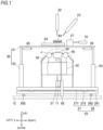
- FIG. 1 is a front view illustrating a schematic configuration of the hair planting apparatus 10
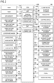
- FIG. 2 is a block diagram illustrating a control system of the hair planting apparatus 10
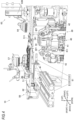
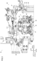
- FIGS. 3 to 5 are perspective views of the hair planting apparatus 10 seen from different directions respectively.
- the hair planting apparatus 10 reduces workload and smoothly plants a hair for planting in a base material J.
- the hair for planting is not limited to human hair and includes all other fibers similar to human hair, including natural fibers and artificial fibers.
- the base material J is not limited to fibrous materials and includes any planar or curved sheet-shaped material, although in the present embodiment, an example of a curved (substantially spherical shell-shaped) sheet that imitates the shape of the top of a human head and that has hexagonal grid-like mesh holes is illustrated.
- the shape of the mesh hole may not be hexagonal.
- the hair planting apparatus 10 includes a base stage 30 on which the base material J is mounted, a feed device 40 that feeds the mounted base material J in one direction (X-axis direction) on its mounting surface and another direction (Y-axis direction) orthogonal to the one direction, a clamp device 50 that holds the base material J mounted on the base stage 30 from above, a first capture mechanism 21 that pulls a hair for planting through a mesh hole on a back side (lower side) of the held base material J to form a small loop, a looper mechanism 24 that expands a small loop (see FIGS.
- a second capture mechanism 22 that pulls the loop on the back side of the hair for planting from a neighboring mesh hole to a surface side (upper side) of the base material J
- a third capture mechanism 23 that pulls one end of the hair for planting into the loop on the surface side of the hair for planting to form a knot
- a transport mechanism 25 that performs a relative transport operation of the held base material J and hook needles of the first to third capture mechanisms 21 to 23.
- the hair planting apparatus 10 includes a camera 11 serving as an imaging unit that captures an image of the mounted base material J, a position switch mechanism 28 that holds the camera 11 and the first capture mechanism 21 and switches the positions thereof, a wiper mechanism 61 that wipes away to the outside of an upper opening 511 the planted hair for planting inserted in the upper opening 511 of a clamp plate 51 to be described below, an auxiliary clamp mechanism 62 that holds the base material J mounted on the base stage 30 in an auxiliary manner, a correction mechanism 63 for correcting the orientation of the base material J on the base stage 30, a first blower mechanism 64 that blows air to orient the hair for planting planted in the base material J in a predetermined direction, a second blower mechanism 65 that blows air to push the base material J to the base stage 30 side, a control device 100 that controls operations of each configuration described above, and a base 12 that directly or indirectly supports each configuration described above.
- a camera 11 serving as an imaging unit that captures an image of the mounted base material J
- a position switch mechanism 28
- the mounting surface on which the base material J is mounted is horizontal, and one side in the Y-axis direction parallel to the mounting surface is referred to as the "left” side and the other side is referred to as the "right” side, while one side in the X-axis direction parallel to the mounting surface is referred to as the "front” side (side close to the paper surface in FIG. 1 ) and the other side is referred to as the "rear” side (side far from the paper surface in FIG. 1 ).
- the vertical up-and-down direction orthogonal to the X-axis direction and the Y-axis direction is referred to as a Z-axis direction
- one side in the Z-axis direction is referred to as the "upper” side while the other side is referred to as the "lower” side.
- first to third capture mechanisms 21 to 23 and the looper mechanism 24 form a hair planting unit 20 that binds the hair for planting to the base material J.
- the base 12 is a flat plate body that directly or indirectly supports the entire configuration of the hair planting apparatus 10.
- An upper surface of the base 12 is horizontal in a state when the hair planting apparatus 10 is installed on the horizontal surface.
- the first capture mechanism 21, the second capture mechanism 22, the position switch mechanism 28 supporting the third capture mechanism 23 and the camera 11, the looper mechanism 24, the wiper mechanism 61, the auxiliary clamp mechanism 62, the correction mechanism 63, and the first blower mechanism 64 described above are directly supported on the base 12.
- the transport mechanism 25 includes an X-axis stage 26 installed on the upper surface of the base 12 and a Y-axis stage 27 installed on the X-axis stage 26.
- the X-axis stage 26 includes a stage plate 261 having an upper surface parallel to the X-Y plane, a slide guide 262 slidably supporting the stage plate 261 in the X-axis direction with respect to the base 12, and a linear transport mechanism (not shown) that allows any transport and positioning of the stage plate 261 in the X-axis direction.
- the linear transport mechanism includes a ball screw mechanism, and an X-axis motor 263 including a servomotor which serves as a drive source of the ball screw mechanism.
- the Y-axis stage 27 includes a stage plate 271 having an upper surface parallel to the X-Y plane, a slide guide 272 slidably supporting the stage plate 271 in the Y-axis direction with respect to the stage plate 261 of the X-axis stage 26, and a linear transport mechanism (not shown) that allows any transport and positioning of the stage plate 271 in the Y-axis direction.
- the linear transport mechanism includes a ball screw mechanism, and a Y-axis motor 273 including a servomotor which serves as a drive source of the ball screw mechanism.
- the base stage 30, the feed device 40, the clamp device 50, and the second blower mechanism 65 are directly supported on the stage plate 271 of the Y-axis stage 27.
- the transport mechanism 25 can position the base material J on the base stage 30 at any position in the X-Y plane by the cooperation between the X-axis stage 26 and the Y-axis stage 27.
- the linear transport mechanism of the X-axis stage 26 and Y-axis stage 27 is not limited to the ball screw mechanism and may be any mechanism that can position the stage plate 261 or 271 anywhere in the X-axis direction or the Y-axis direction.
- the linear transport of the stage plate 261 or 271 may be implemented by a configuration of a pinion-rack mechanism and a servomotor, or the stage plate 261 or 271 may be linearly transported by a linear motor.
- FIG. 6 is a plan view of the base stage 30, and FIG. 7 is a perspective view.
- the base stage 30 includes a base plate 32 supported by four posts 31 (one is not shown in the drawing) erected on the Y-axis stage 27 of the transport mechanism 25, a tower-like erected part 33 provided on the upper surface of the base plate 32, and a mounting plate 34 serving as a mounting portion provided at an upper end of the erected part 33.
- the erected part 33 is erected at a center portion of the base plate 32 in the plan view.
- the mounting plate 34 provided at the upper end of the erected part 33 is a substantially rectangular frame-like body, and includes a work opening 341 in a substantially rectangular shape formed in the center portion. Further, an upper surface of the mounting plate 34 is a mounting surface parallel to the X-Y plane.
- the base material J is mounted on the mounting surface which is the upper surface of the mounting plate 34.
- the mounting plate 34 is smaller than the base material J, and the base material J is mounted with the lower surface portion thereof being in partial contact with the mounting plate 34.
- the feed device 40 includes, on the base plate 32 of the base stage 30, a pair of X-axis roller mechanisms 41, 41 disposed on both sides of the mounting plate 34 in the X-axis direction in a plan view, and a pair of Y-axis roller mechanisms 42, 42 disposed on both sides of the mounting plate 34 in the Y-axis direction in a plan view.
- Each of the X-axis roller mechanisms 41 includes a roller 411 contacting from below the base material J mounted on the mounting surface of the mounting plate 34, an X-axis feed motor 412 serving as a rotational drive source of the roller 411, a support bracket 413 supporting the roller 411 and the X-axis feed motor 412, two slide guides 414 movably supporting the support bracket 413 on the base plate 32 up and down in the Z-axis direction, two coil springs 415 serving as elastic members to urge the support bracket 413 upward, and a retraction air cylinder 416 pulling the support bracket 413 downward against the coil springs 415.
- the X-axis feed motor 412 supported by the support bracket 413 imparts a feed rotation from an output shaft to a rotating shaft of the roller 411, by a transmission mechanism including a pulley and a timing belt.
- the output shaft of the X-axis feed motor 412 and the rotating shaft of the roller 411 are both disposed in the Y-axis direction. Therefore, when the roller 411 performs rotational driving in contact with the base material J from below, mounted on the mounting surface of the mounting plate 34, the base material J can be fed in the X-axis direction.
- Each of the Y-axis roller mechanisms 42 includes a roller 421 contacting the base material J from below, mounted on the mounting surface of the mounting plate 34, a Y-axis feed motor 422 serving as a rotational drive source of the roller 421, a support bracket 423 supporting the roller 421 and the Y-axis feed motor 422, a slide guide 424 movably supporting the support bracket 423 on the base plate 32 up and down in the Z-axis direction, coil springs 425 serving as elastic members to urge the support bracket 423 upward, and a retraction air cylinder 426 pulling the support bracket 423 downward against the coil springs 425.
- the Y-axis feed motor 422 supported by the support bracket 423 imparts the feed rotation from the output shaft to the rotating shaft of the roller 421, by a transmission mechanism including a pulley and a timing belt.
- the output shaft of the Y-axis feed motor 422 and the rotating shaft of the roller 421 are both disposed in the X-axis direction. Therefore, when the roller 421 performs rotational driving in contact with the base material J from below, mounted on the mounting surface of the mounting plate 34, the base material J can be fed in the Y-axis direction.
- the height of the upper ends of the respective rollers 411 and 421 is respectively set so as to match the height of the mounting surface (upper surface) of the mounting plate 34 or be slightly lower than the mounting surface of the mounting plate 34.
- the respective rollers 411 and 421 at this height are at a "feed position" respectively.
- the X-axis roller mechanisms 41 and the Y-axis roller mechanisms 42 perform the transport in the X-axis direction and the transport in the Y-axis direction separately rather than simultaneously.
- tension imparting control the operation control of imparting tension to the base material J in each direction by the pair of X-axis roller mechanisms 41 or the pair of Y-axis roller mechanisms 42 is referred to as "tension imparting control”.
- the transport mechanism 25 described above is used for transporting the base material J together with the mounting plate 34, and positioning each mesh hole of the base material J in the range of the work opening 341 with respect to the hook needles of the first to third capture mechanisms 21 to 23.
- the feed device 40 is used for transporting the base material J with respect to the mounting plate 34 and shifting the range of the base material J facing the work opening 341 of the mounting plate 34 to another position in the base material J.
- the transport of the base material J by the transport mechanism 25 is finely controlled by a very small amount of transport compared with the transport of the base material J by the feed device 40.
- roller mechanisms 41 and 42 in two intersecting directions respectively perform the feed in the X-axis direction and the Y-axis direction orthogonal to each other
- aspects are not limited thereto, and the configuration in which the feed is performed in two diagonally intersecting directions is also possible.
- the base stage 30 includes a cover member 35 covering the base stage 30 and the feed device 40.
- the cover member 35 has a substantially convex polyhedron shape with an upper end thereof protruding upward, and the center of the upper end is widely notched such that the upper portions of the rollers 411 and 421 and the mounting plate 34 are respectively exposed upward therethrough.
- the upper end of the base stage 30 may have a polyhedral shape similar to a spherical shell or may have a substantially spherical shell shape.
- the base material J mounted on the mounting plate 34 is prevented from a direct contact with the configurations other than the respective rollers 411 and 421 of the feed device 40 or with the corners of the base plate 32, allowing a smooth feed operation of the base material J by the feed device 40.
- the cover member 35 is omitted in drawings other than FIG. 1 .
- the clamp device 50 includes a clamp plate (clamp member) 51 including a flat plate body elongated in the Y-axis direction above the base stage 30, a pair of support bases 52 erected on the upper surface of the stage plate 271 of the Y-axis stage 27 to individually support both ends of the clamp plate 51, a slide guide 53 that allows lifting and lowering of the clamp plate 51 with respect to each support base 52, a clamp air cylinder 54 serving as an elevating part that lifts and lowers the clamp plate 51, and a coil spring 55 provided between each support base 52 and the clamp plate 51 and serving as an elastic member urging the clamp plate 51 upward.
- a clamp plate (clamp member) 51 including a flat plate body elongated in the Y-axis direction above the base stage 30, a pair of support bases 52 erected on the upper surface of the stage plate 271 of the Y-axis stage 27 to individually support both ends of the clamp plate 51, a slide guide 53 that allows lifting and lowering of the clamp plate 51 with respect to each support base
- the transport mechanism 25 transports the clamp device 50 together with the base stage 30 in the X-Y plane.
- the clamp plate 51 is directly above the work opening 341 of the mounting plate 34 and has an upper opening 511 in substantially the same shape and size as the work opening 341, extending in the up-and-down direction.
- the lower surface of the clamp plate 51 can be brought into contact with the mounting surface of the mounting plate 34 at a lower limit position of the lifting and lowering operation.
- the clamp plate 51 can be lowered to the lower limit position and clamp the base material J mounted on the mounting plate 34 from above to fixedly hold the base material J.
- the work opening 341 and the upper opening 511 of the mounting plate 34 can be overlapped at substantially the same position in the plan view.
- the second and third capture mechanisms 22 and 23 described above are disposed above the clamp plate 51, and extend the hook needles downward to perform the operations of binding the hair for planting within the range of the work opening 341 of the base material J through the upper opening 511.
- each contact plate 512 individually contacting the outer circumference of the respective rollers 411 and 421 are provided on four sides of the upper opening 511 on the lower surface side of the clamp plate 51.
- the lower surface of each contact plate 512 is positioned lower than the lower surface of the clamp plate 51 and contacts the upper portions of the respective rollers 411 and 421 at a position short of the lower limit position of the lifting and lowering operation of the clamp plate 51.
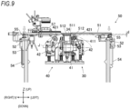
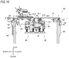
- FIGS. 8 to 10 are front views of the clamp device 50 with the clamp plate 51 at different heights respectively.
- FIG. 8 illustrates the clamp plate 51 positioned at a lifted position, which is the upper limit of the lifting and lowering operation, by the upward pressure of each clamp air cylinder 54. In this state, the lower surface of the clamp plate 51 is separated far away from the mounting surface of the mounting plate 34.
- the base material J on the mounting plate 34 is in the unclamped state. Since the clamp plate 51 at the lifted position is separated far away from the mounting plate 34, the hair for planting can be swept through a wiper member 611 of the wiper mechanism 61 to be described below.
- Each clamp air cylinder 54 is provided with a regulator 56 in the supply path from the pneumatic source, and air pressure for lowering the clamp plate 51 can be applied to each clamp air cylinder 54 in two stages, high and low, by the control of the control device 100.
- FIG. 9 illustrates the clamp plate 51 when the downward pressure of each clamp air cylinder 54 is low
- FIG. 10 illustrates the clamp plate 51 when the downward pressure of each clamp air cylinder 54 is high.
- each clamp air cylinder 54 when the downward pressure of each clamp air cylinder 54 is low, the lowered clamp plate 51 cannot withstand the upward urging force received from the coil springs 55 such that a gap d is formed between the lower surface of the clamp plate 51 and the mounting surface of the mounting plate 34, and the base material J is restrained by a small or no restraining force of the clamp.
- the height of the clamp plate 51 at this time is referred to as a weak clamp position.
- each contact plate 512 of the clamp plate 51 contacts the respective rollers 411 and 421 or forms a very narrow gap with respect to the respective rollers 411 and 421. Therefore, when the base material J is mounted on the mounting plate 34, the base material J is pressed by each contact plate 512 into contact with the respective rollers 411 and 421 with appropriate contact force such that the feed operation by the pair of X-axis roller mechanisms 41 or the pair of Y-axis roller mechanisms 42 can be performed properly.
- each clamp air cylinder 54 when the downward pressure of each clamp air cylinder 54 is high, the clamp plate 51 can be lowered against the coil springs 55 such that the lower surface of the clamp plate 51 and the mounting surface of the mounting plate 34 can be brought into pressed contract state. Therefore, when the base material J is mounted on the mounting plate 34, the base material J is firmly gripped by the clamp plate 51 and the mounting plate 34 and fixedly held with a large restraining force. The height of the clamp plate 51 at this time is referred to as a strong clamp position.
- a lighting device 57 is provided on the upper surface of the mounting plate 34.
- the lighting device 57 irradiates illumination light from above the upper opening 511 when the camera 11, which will be described below, captures images of the base material J through the work opening 341 from below the mounting plate 34.
- the lighting device 57 is in a retracted position at one end side of the clamp plate 51 when no image is captured, and is moved directly above the upper opening 511 by an actuator (not shown) to perform illumination when the image is captured.
- the auxiliary clamp mechanisms 62 are provided on both sides of the base stage 30 in the X-axis direction.
- the two auxiliary clamp mechanisms 62 are disposed to face two X-axis roller mechanisms 41 individually.
- Each of the auxiliary clamp mechanisms 62 includes an auxiliary clamp plate 621 which is tiltable, and an auxiliary clamp air cylinder 622 for tilting the auxiliary clamp plate 621.
- the auxiliary clamp plate 621 is formed in a shape of a flat plate with a base end being tiltably supported about the Y-axis and a tip end contacting the outer circumferential surface of the roller 411 of the X-axis roller mechanism 41.
- the auxiliary clamp air cylinder 622 imparts tilting force in a direction in which the tip end of the auxiliary clamp plate 621 contacts the outer circumferential surface of the roller 411.
- the base material J mounted on the mounting plate 34 is sandwiched and held in position between the X-axis roller mechanism 41 and the tip end of the auxiliary clamp plate 621.
- the two auxiliary clamp mechanisms 62 are provided to press the base material J so as to prevent misalignment between the base material J and the mounting plate 34, when the clamp plate 51 of the clamp device 50 is in the lifted position where the base material J of the mounting plate 34 is released from restraint.
- the base material J When the base material J is clamped by the two auxiliary clamp mechanisms 62, the base material J is likely to loosen due to the pressing by the tip end of the auxiliary clamp plate 621. In view of this, it is preferable to simultaneously perform the control of applying tension by the pair of X-axis roller mechanisms 41 described above.
- the wiper mechanism 61 is a mechanism for wiping away the hair for planting bound to the base material J.
- the operation of planting hair on the base material J is performed through the work opening 341 and the upper opening 511 while the base material J is held by the clamp plate 51.
- each hair for planting in the planted state remains inserted in the upper opening 511, it may possibly affect the feed operation of the base material J, the binding operation of the hair for planting in the next section, the image capturing of a new section through the work opening 341, and the like.
- the clamp plate 51 is lifted to the lifted position, and the operation of wiping, with the wiper mechanism 61, the hair for planting bound to the base material J under the clamp plate 51 and wiping each hair for planting from the upper opening 511 is performed.
- the operation of feeding the base material J and the operation of wiping the hair for planting may be performed in a switched order.
- the wiper mechanism 61 is disposed on a rear right side of the mounting plate 34 in the plan view. Further, the wiper mechanism 61 is disposed lower than the clamp plate 51 at the lifted position and higher than the mounting plate 34.
- the wiper mechanism 61 includes a rod-shaped wiper member 611 for wiping each hair for planting, a telescopic air cylinder 612 extending and contracting the wiper member 611, and a wiping air cylinder 613 that imparts the wiper member 611 forward and backward movement for wiping.
- the wiper member 611 is a round bar-shaped member formed in the Y-axis direction and extends leftward from the telescopic air cylinder 612.
- the telescopic air cylinder 612 is supported by the wiping air cylinder 613 so that a plunger moving forward and backward is parallel to the Y-axis direction.
- the plunger of the telescopic air cylinder 612 is connected to the wiper member 611 in the extending direction thereof and can switch between contracting the wiper member 611 rightward and extending the wiper member 611 leftward.
- the wiper member 611 In the contracting state, the wiper member 611 is positioned to the right of the mounting plate 34, and in the extending state, overlaps the mounting plate 34 in the Y-axis direction.
- the wiping air cylinder 613 is supported by the base 12 so that the plunger is parallel to the X-axis direction. Then, it is possible to support the telescopic air cylinder 612 at the tip end of the plunger, and move the wiper member 611 forward of the mounting plate 34 when the plunger is advanced, and backward of the mounting plate 34 when the plunger is retracted.
- the wiper member 611 may take any form as long as the wiper member 611 can wipe away the hair for planting.
- the wiper member 611 is not limited to a round bar shape and may take the shape of a plate or a brush.
- the CPU 101 is connected to the clamp device 50, controls the clamp air cylinder 54 through an electromagnetic valve (not shown), and controls the strength of the air pressure supplied to the clamp air cylinder 54 with the regulator 56.
- the CPU 101 is connected to the auxiliary clamp mechanism 62 and controls the auxiliary clamp air cylinder 622 through an electromagnetic valve (not shown).
- Both the first blower mechanism 64 and the second blower mechanism 65 include electromagnetic valves for supplying high-pressure air to the nozzles, and the CPU 101 controls each electromagnetic valve to control the discharge of the air.
- the CPU 101 is connected to the camera 11.
- the CPU 101 is connected to a pedal 14 for inputting the start of the hair planting operation.
- the CPU 101 is also connected to an operation panel 15 having a function as a display unit for displaying various information and a function as an input unit for performing various inputs.
- the CPU 101 also includes software modules such as a feed control unit 105, a tension application control unit 106, a state switch control unit 107, a tilt detection unit 108, a correction control unit 109, and the like. It is to be noted that part or all of these software modules may be configured from hardware.
- the CPU 101 controls various air cylinders, various motors, various actuators, and the like with electromagnetic valves, drive circuits, interfaces, and the like.
- electromagnetic valves, drive circuits, and interfaces will be omitted, and it will simply be described that various air cylinders, various motors, various actuators, and the like are controlled.
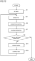
- a flow chart of FIG. 13 shows the overall flow of operation control of the hair planting operation executed by the CPU 101.
- the CPU 101 controls the clamp air cylinder 54 of the clamp device 50 to move the clamp plate 51 to the lifted position, and controls the auxiliary clamp air cylinders 622 of the respective auxiliary clamp mechanisms 62 to move the auxiliary clamp plates 621 to the released position separated from the X-axis roller mechanism 41.
- step S1 the CPU 101 executes a process of base set.
- the state switch control unit 107 supplies low air pressure to the clamp air cylinder 54 from the regulator 56 to lower the clamp plate 51 of the clamp device 50 to the weak clamp position (step S49).
- the clamp plate 51 appropriately presses the base material J against the rollers 411 and 421 of the X-axis roller mechanism 41 and the Y-axis roller mechanism 42, respectively, thereby enabling smooth feeding, and feeding the base material J with high accuracy.
- components that are integrally formed from a single member may be replaced with components that are split into multiple members and coupled or affixed together.
- a component configured by connecting a plurality of members may be replaced with a component integrally formed by a single member.
- Other details shown in the embodiments can be changed as appropriate without departing from the scope of the present disclosure.
- the correction mechanism 66 includes a bearing 662 directly provided on the upper surface of the base 12 and allows rotation about the Z-axis passing through the center of the work opening 341 of the mounting plate 34, a rotation stage 661 rotatably supported by the bearing 662, and a rotation mechanism (not shown) that imparts a rotational force to the rotation stage 661.
- the rotation mechanism includes a drive source such as a servomotor that enables the control device 100 to control the rotation angle.
- the transport mechanism 25 (X-axis stage 26 and the Y-axis stage 27), the base stage 30 including the mounting plate 34, the wiper mechanism 61, the auxiliary clamp mechanism 62, the first blower mechanism 64, the second blower mechanism 65, the feed device 40, and the clamp device 50 are mounted directly or indirectly on the rotation stage 661 of the correction mechanism 66 and applied with rotational motion around the Z-axis with respect to the base 12.
- the first capture mechanism 21, the second capture mechanism 22, the third capture mechanism 23, the position switch mechanism 28 that supports the camera 11, and the looper mechanism 24 are mounted on the base 12 and applied with no rotation by the correction mechanism 66.
- the holding mechanism 67 includes the support shaft 632 rotatably supported around the Z-axis by the bracket 631 installed on the base 12, the arm 633 fixed to the upper end of the support shaft 632, the pressing plate provided at the tip end of the arm 633, the arm turning air cylinder 636 that imparts rotational motion to the support shaft 632, the spline nut 637, the coil spring 638, and the pressing air cylinder 639 that lowers the arm 633 (see FIGS. 2 and 5 ).
- the holding mechanism 67 differs from the correction mechanism 63 described above in that the pressing plate is fixedly supported by the arm 633 and does not include the correction motor 635 for rotating the pressing plate.
- the correction control performed by the correction control unit 109 on the hair planting apparatus 10 including the correction mechanism 66 and the holding mechanism 67 will be described with reference to the flowchart of FIG. 17 .
- the correction control by the correction mechanism 66 is performed at the same timing as the correction control shown in step S5 in the flowchart of FIG. 13 described above.
- step S71 The tilt detection described above (see step S3 in FIG. 13 ) is performed immediately before the correction control, and the correction control unit 109 turns off the lighting device 57 used at that time and retracts it from the upper opening 511 (step S71).
- correction control unit 109 controls the feed device 40, the clamp device 50, and the auxiliary clamp mechanism 62 in parallel.
- the correction control unit 109 controls the retraction air cylinders 416 and 426 of the pair of X-axis roller mechanisms 41 and the pair of Y-axis roller mechanisms 42 of the feed device 40 to lower the respective rollers 411 and 421 to the retraction positions (step S73).
- the correction control unit 109 controls the auxiliary clamp air cylinders 622 of the respective auxiliary clamp mechanisms 62 to return the respective auxiliary clamp plates 621 to the auxiliary clamping state (step S91). Furthermore, the tension application control unit 106 executes tension application control by the X-axis feed motors 412 of the pair of X-axis roller mechanisms 41 (step S93).
- the correction control unit 109 controls the drive source of the correction mechanism 66 to rotate the rotation stage 661 by the same tilt angle ⁇ as the tilt angle ⁇ of the base material J detected by the tilt detection unit 108 in a direction opposite to the direction in which the tilt occurs (step S101).
Landscapes
- Engineering & Computer Science (AREA)
- Textile Engineering (AREA)
- Chemical & Material Sciences (AREA)
- Materials Engineering (AREA)
- Surgical Instruments (AREA)
- Sewing Machines And Sewing (AREA)
Claims (6)
- Vorrichtung (10) zum Einbringen eines Haarbesatzes, umfassend:einen Montagebereich (34), welcher ausgebildet ist zum Montieren eines Basismaterials (J), an welchem ein Besatz eingebracht wird, und welcher eine Arbeitsöffnung (341) zum Einbringen des Besatzes umfasst;eine Haarbesatzeinheit (20) zum Anbinden von Besatzhaar an das Basismaterial (J) in der Arbeitsöffnung (341) des Montagebereichs (34);eine Zuführungseinrichtung (40), welche um den Montagebereich (34) herum angeordnet ist und das Basismaterial (J) über mindestens zwei Rollen (411, 421) zuführt, welche mit dem Basismaterial (J) von unten in Kontakt treten,wobei die Zuführungseinrichtung (40) das Basismaterial (J) in mindestens zwei einander kreuzenden Richtungen zuführt;eine Zuführungssteuereinheit (105), welche die Zuführungseinrichtung (40) steuert, um das Basismaterial (J) gemäß einer vorbestimmten Abschnittseinheit für eine Haarbesatzoperation zuzuführen.
- Vorrichtung zum Einbringen eines Haarbesatzes nach Anspruch 1, wobei die Zuführungseinrichtung (40) zwei Rollen (411, 421) umfasst, welche bei hierzwischen angeordnetem Montagebereich (34) in jeder Zuführungsrichtung angeordnet sind.
- Vorrichtung zum Einbringen eines Haarbesatzes nach Anspruch 2, wobei die Zuführungseinrichtung (40) separate Antriebsquellen (412, 422) für die zwei Rollen (411, 421) aufweist, welche bei hierzwischen angeordnetem Montagebereich (34) in jeder Zuführungsrichtung angeordnet sind, und wobei die Vorrichtung (10) ferner umfasst:
eine Spannungsbeaufschlagungssteuereinheit (106), welche die Antriebsquellen (412, 422) für die zwei Rollen (411, 421) in einander entgegengesetzten Richtungen in Rotation versetzt, um das Basismaterial (J) mit Spannung zu beaufschlagen. - Vorrichtung zum Einbringen eines Haarbesatzes nach einem der Ansprüche 1 bis 3, ferner umfassend eine Klemmeinrichtung (50), welche ein Klemmglied (51) umfasst, welches das an dem Montagebereich (34) montierte Basismaterial (J) von oben andrückt, und ein Hubteil (54), welches das Klemmglied (51) anhebt und absenkt.
- Vorrichtung zum Einbringen eines Haarbesatzes nach Anspruch 4, wobei das Hubteil (54) mit einer Zustandsschaltsteuereinheit (107) bereitgestellt ist, welche eine Druckkraft in einer Höhen- oder Absenkrichtung des Klemmglieds (51) während einer Absenkbewegung steuert, so dass das Basismaterial (J) zwischen einem Rückhaltezustand und einem Zuführungsfreigabezustand umgeschaltet wird.
- Vorrichtung zum Einbringen eines Haarbesatzes nach Anspruch 4 oder 5, wobei das Klemmglied (51) umfasst:eine obere Öffnung (511), welche der Arbeitsöffnung (341) des Montagebereichs (34) zugewandt ist; undeinen Wischmechanismus (61) zum Wegwischen des gesetzten Besatzhaars, welches an das Basismaterial gebunden ist, zur Außenseite der oberen Öffnung (511).
Applications Claiming Priority (1)
| Application Number | Priority Date | Filing Date | Title |
|---|---|---|---|
| JP2022044919A JP7763128B2 (ja) | 2022-03-22 | 2022-03-22 | 植毛装置 |
Publications (2)
| Publication Number | Publication Date |
|---|---|
| EP4249657A1 EP4249657A1 (de) | 2023-09-27 |
| EP4249657B1 true EP4249657B1 (de) | 2025-06-25 |
Family
ID=85704628
Family Applications (1)
| Application Number | Title | Priority Date | Filing Date |
|---|---|---|---|
| EP23162856.1A Active EP4249657B1 (de) | 2022-03-22 | 2023-03-20 | Haarpflanzgerät |
Country Status (4)
| Country | Link |
|---|---|
| US (1) | US12538954B2 (de) |
| EP (1) | EP4249657B1 (de) |
| JP (1) | JP7763128B2 (de) |
| CN (1) | CN116784551A (de) |
Families Citing this family (2)
| Publication number | Priority date | Publication date | Assignee | Title |
|---|---|---|---|---|
| JP7368193B2 (ja) * | 2019-11-15 | 2023-10-24 | Juki株式会社 | 毛髪供給装置 |
| JP2025033593A (ja) | 2023-08-30 | 2025-03-13 | キヤノン株式会社 | 振動型駆動装置 |
Family Cites Families (12)
| Publication number | Priority date | Publication date | Assignee | Title |
|---|---|---|---|---|
| JPS63219655A (ja) | 1987-03-10 | 1988-09-13 | 三菱電機株式会社 | 植毛機の植毛材供給装置 |
| JPS63315658A (ja) * | 1987-06-15 | 1988-12-23 | 三菱電機株式会社 | 植毛機の植毛材引締め装置 |
| JP2727458B2 (ja) * | 1988-10-28 | 1998-03-11 | 株式会社アデランス | かつら植毛機の毛払いユニット |
| JPH03119166A (ja) * | 1989-10-03 | 1991-05-21 | Tokai Ind Sewing Mach Co Ltd | 刺繍縫いミシン |
| DE10000986C1 (de) * | 1999-12-13 | 2001-09-27 | Ulrich Werner | Haarverknotungsvorrichtung |
| KR100725606B1 (ko) * | 2000-04-28 | 2007-06-08 | 프로피아 가부시끼 가이샤 | 전자동 가발제조기 및 가발의 제조방법 |
| JP3561840B2 (ja) * | 2001-09-28 | 2004-09-02 | 保 知 宏 | かつら製造用自動植毛機及びかつらの製造方法 |
| JP2007315658A (ja) * | 2006-05-25 | 2007-12-06 | Fuji Alpha:Kk | 廃タイヤ焼却装置 |
| KR101242682B1 (ko) * | 2010-07-16 | 2013-03-12 | 김관진 | 가발용 캡 성형장치 및 캡 성형방법 |
| JP6727996B2 (ja) | 2016-09-08 | 2020-07-22 | Juki株式会社 | 植毛装置 |
| JP7246967B2 (ja) * | 2019-02-25 | 2023-03-28 | Juki株式会社 | 植毛装置 |
| JP7252782B2 (ja) * | 2019-02-25 | 2023-04-05 | Juki株式会社 | 植毛装置 |
-
2022
- 2022-03-22 JP JP2022044919A patent/JP7763128B2/ja active Active
-
2023
- 2023-03-20 US US18/123,533 patent/US12538954B2/en active Active
- 2023-03-20 EP EP23162856.1A patent/EP4249657B1/de active Active
- 2023-03-22 CN CN202310283178.0A patent/CN116784551A/zh active Pending
Also Published As
| Publication number | Publication date |
|---|---|
| US20230301383A1 (en) | 2023-09-28 |
| JP7763128B2 (ja) | 2025-10-31 |
| CN116784551A (zh) | 2023-09-22 |
| US12538954B2 (en) | 2026-02-03 |
| EP4249657A1 (de) | 2023-09-27 |
| JP2023139406A (ja) | 2023-10-04 |
Similar Documents
| Publication | Publication Date | Title |
|---|---|---|
| EP4249657A1 (de) | Haarpflanzgerät | |
| EP4248782A1 (de) | Haarpflanzgerät | |
| JP6728834B2 (ja) | 布把持装置 | |
| KR101511936B1 (ko) | 단추공급장치 | |
| US10889103B2 (en) | Screen printer and screen printing method | |
| US9475275B2 (en) | Screen printing apparatus | |
| JP7203347B2 (ja) | 部品供給装置及び部品装着装置 | |
| JP7252782B2 (ja) | 植毛装置 | |
| JP2017169761A (ja) | 布押え装置と布押え装置を備えたミシン | |
| US20260083197A1 (en) | Hair planting apparatus | |
| US6662737B2 (en) | Mattress label sewing clamp | |
| US20260083198A1 (en) | Detection method and hair planting apparatus | |
| JP4846704B2 (ja) | チップ部品装着装置 | |
| CN114287175A (zh) | 元件装配机 | |
| EP2724862B1 (de) | Bildschirmdruckvorrichtung | |
| JP7333150B2 (ja) | スクリーン印刷機 | |
| JP2020064906A (ja) | 部品装着装置、及び、部品装着方法 | |
| JP2005197758A (ja) | 電子部品搭載装置および電子部品搭載方法 | |
| WO1997044516A1 (en) | Over edging apparatus for single cloth piece products such as handkerchiefs | |
| JP2021160078A (ja) | 冊子の紙面めくり装置及び紙面スキャンシステム | |
| JP2004047818A (ja) | 部品実装装置 | |
| JP2023089747A (ja) | 部品実装機 | |
| JPH0674231U (ja) | 部品供給移送装置 | |
| JP2004273757A (ja) | 電子部品搭載装置および電子部品搭載方法 | |
| JPH0531778U (ja) | 布地供給装置 |
Legal Events
| Date | Code | Title | Description |
|---|---|---|---|
| PUAI | Public reference made under article 153(3) epc to a published international application that has entered the european phase |
Free format text: ORIGINAL CODE: 0009012 |
|
| STAA | Information on the status of an ep patent application or granted ep patent |
Free format text: STATUS: THE APPLICATION HAS BEEN PUBLISHED |
|
| AK | Designated contracting states |
Kind code of ref document: A1 Designated state(s): AL AT BE BG CH CY CZ DE DK EE ES FI FR GB GR HR HU IE IS IT LI LT LU LV MC ME MK MT NL NO PL PT RO RS SE SI SK SM TR |
|
| STAA | Information on the status of an ep patent application or granted ep patent |
Free format text: STATUS: REQUEST FOR EXAMINATION WAS MADE |
|
| 17P | Request for examination filed |
Effective date: 20240327 |
|
| RBV | Designated contracting states (corrected) |
Designated state(s): AL AT BE BG CH CY CZ DE DK EE ES FI FR GB GR HR HU IE IS IT LI LT LU LV MC ME MK MT NL NO PL PT RO RS SE SI SK SM TR |
|
| GRAP | Despatch of communication of intention to grant a patent |
Free format text: ORIGINAL CODE: EPIDOSNIGR1 |
|
| STAA | Information on the status of an ep patent application or granted ep patent |
Free format text: STATUS: GRANT OF PATENT IS INTENDED |
|
| INTG | Intention to grant announced |
Effective date: 20250129 |
|
| GRAS | Grant fee paid |
Free format text: ORIGINAL CODE: EPIDOSNIGR3 |
|
| GRAA | (expected) grant |
Free format text: ORIGINAL CODE: 0009210 |
|
| STAA | Information on the status of an ep patent application or granted ep patent |
Free format text: STATUS: THE PATENT HAS BEEN GRANTED |
|
| AK | Designated contracting states |
Kind code of ref document: B1 Designated state(s): AL AT BE BG CH CY CZ DE DK EE ES FI FR GB GR HR HU IE IS IT LI LT LU LV MC ME MK MT NL NO PL PT RO RS SE SI SK SM TR |
|
| REG | Reference to a national code |
Ref country code: GB Ref legal event code: FG4D |
|
| REG | Reference to a national code |
Ref country code: CH Ref legal event code: EP |
|
| REG | Reference to a national code |
Ref country code: CH Ref legal event code: EP |
|
| REG | Reference to a national code |
Ref country code: IE Ref legal event code: FG4D |
|
| REG | Reference to a national code |
Ref country code: DE Ref legal event code: R096 Ref document number: 602023004188 Country of ref document: DE |
|
| PG25 | Lapsed in a contracting state [announced via postgrant information from national office to epo] |
Ref country code: FI Free format text: LAPSE BECAUSE OF FAILURE TO SUBMIT A TRANSLATION OF THE DESCRIPTION OR TO PAY THE FEE WITHIN THE PRESCRIBED TIME-LIMIT Effective date: 20250625 |
|
| REG | Reference to a national code |
Ref country code: LT Ref legal event code: MG9D |
|
| PG25 | Lapsed in a contracting state [announced via postgrant information from national office to epo] |
Ref country code: NO Free format text: LAPSE BECAUSE OF FAILURE TO SUBMIT A TRANSLATION OF THE DESCRIPTION OR TO PAY THE FEE WITHIN THE PRESCRIBED TIME-LIMIT Effective date: 20250925 Ref country code: GR Free format text: LAPSE BECAUSE OF FAILURE TO SUBMIT A TRANSLATION OF THE DESCRIPTION OR TO PAY THE FEE WITHIN THE PRESCRIBED TIME-LIMIT Effective date: 20250926 |
|
| PG25 | Lapsed in a contracting state [announced via postgrant information from national office to epo] |
Ref country code: BG Free format text: LAPSE BECAUSE OF FAILURE TO SUBMIT A TRANSLATION OF THE DESCRIPTION OR TO PAY THE FEE WITHIN THE PRESCRIBED TIME-LIMIT Effective date: 20250625 |
|
| PG25 | Lapsed in a contracting state [announced via postgrant information from national office to epo] |
Ref country code: HR Free format text: LAPSE BECAUSE OF FAILURE TO SUBMIT A TRANSLATION OF THE DESCRIPTION OR TO PAY THE FEE WITHIN THE PRESCRIBED TIME-LIMIT Effective date: 20250625 |
|
| PG25 | Lapsed in a contracting state [announced via postgrant information from national office to epo] |
Ref country code: RS Free format text: LAPSE BECAUSE OF FAILURE TO SUBMIT A TRANSLATION OF THE DESCRIPTION OR TO PAY THE FEE WITHIN THE PRESCRIBED TIME-LIMIT Effective date: 20250925 |
|
| PG25 | Lapsed in a contracting state [announced via postgrant information from national office to epo] |
Ref country code: LV Free format text: LAPSE BECAUSE OF FAILURE TO SUBMIT A TRANSLATION OF THE DESCRIPTION OR TO PAY THE FEE WITHIN THE PRESCRIBED TIME-LIMIT Effective date: 20250625 |
|
| REG | Reference to a national code |
Ref country code: NL Ref legal event code: MP Effective date: 20250625 |
|
| PG25 | Lapsed in a contracting state [announced via postgrant information from national office to epo] |
Ref country code: NL Free format text: LAPSE BECAUSE OF FAILURE TO SUBMIT A TRANSLATION OF THE DESCRIPTION OR TO PAY THE FEE WITHIN THE PRESCRIBED TIME-LIMIT Effective date: 20250625 |
|
| PG25 | Lapsed in a contracting state [announced via postgrant information from national office to epo] |
Ref country code: PT Free format text: LAPSE BECAUSE OF FAILURE TO SUBMIT A TRANSLATION OF THE DESCRIPTION OR TO PAY THE FEE WITHIN THE PRESCRIBED TIME-LIMIT Effective date: 20251027 |
|
| REG | Reference to a national code |
Ref country code: AT Ref legal event code: MK05 Ref document number: 1806530 Country of ref document: AT Kind code of ref document: T Effective date: 20250625 |
|
| PG25 | Lapsed in a contracting state [announced via postgrant information from national office to epo] |
Ref country code: IS Free format text: LAPSE BECAUSE OF FAILURE TO SUBMIT A TRANSLATION OF THE DESCRIPTION OR TO PAY THE FEE WITHIN THE PRESCRIBED TIME-LIMIT Effective date: 20251025 |
|
| PG25 | Lapsed in a contracting state [announced via postgrant information from national office to epo] |
Ref country code: AT Free format text: LAPSE BECAUSE OF FAILURE TO SUBMIT A TRANSLATION OF THE DESCRIPTION OR TO PAY THE FEE WITHIN THE PRESCRIBED TIME-LIMIT Effective date: 20250625 Ref country code: SM Free format text: LAPSE BECAUSE OF FAILURE TO SUBMIT A TRANSLATION OF THE DESCRIPTION OR TO PAY THE FEE WITHIN THE PRESCRIBED TIME-LIMIT Effective date: 20250625 |
|
| PG25 | Lapsed in a contracting state [announced via postgrant information from national office to epo] |
Ref country code: CZ Free format text: LAPSE BECAUSE OF FAILURE TO SUBMIT A TRANSLATION OF THE DESCRIPTION OR TO PAY THE FEE WITHIN THE PRESCRIBED TIME-LIMIT Effective date: 20250625 |
|
| PG25 | Lapsed in a contracting state [announced via postgrant information from national office to epo] |
Ref country code: PL Free format text: LAPSE BECAUSE OF FAILURE TO SUBMIT A TRANSLATION OF THE DESCRIPTION OR TO PAY THE FEE WITHIN THE PRESCRIBED TIME-LIMIT Effective date: 20250625 |
|
| PG25 | Lapsed in a contracting state [announced via postgrant information from national office to epo] |
Ref country code: EE Free format text: LAPSE BECAUSE OF FAILURE TO SUBMIT A TRANSLATION OF THE DESCRIPTION OR TO PAY THE FEE WITHIN THE PRESCRIBED TIME-LIMIT Effective date: 20250625 |
|
| PG25 | Lapsed in a contracting state [announced via postgrant information from national office to epo] |
Ref country code: SK Free format text: LAPSE BECAUSE OF FAILURE TO SUBMIT A TRANSLATION OF THE DESCRIPTION OR TO PAY THE FEE WITHIN THE PRESCRIBED TIME-LIMIT Effective date: 20250625 |
|
| PG25 | Lapsed in a contracting state [announced via postgrant information from national office to epo] |
Ref country code: ES Free format text: LAPSE BECAUSE OF FAILURE TO SUBMIT A TRANSLATION OF THE DESCRIPTION OR TO PAY THE FEE WITHIN THE PRESCRIBED TIME-LIMIT Effective date: 20250625 |
|
| REG | Reference to a national code |
Ref country code: DE Ref legal event code: R097 Ref document number: 602023004188 Country of ref document: DE |
|
| PG25 | Lapsed in a contracting state [announced via postgrant information from national office to epo] |
Ref country code: DK Free format text: LAPSE BECAUSE OF FAILURE TO SUBMIT A TRANSLATION OF THE DESCRIPTION OR TO PAY THE FEE WITHIN THE PRESCRIBED TIME-LIMIT Effective date: 20250625 |
|
| PGFP | Annual fee paid to national office [announced via postgrant information from national office to epo] |
Ref country code: DE Payment date: 20260128 Year of fee payment: 4 |
|
| PG25 | Lapsed in a contracting state [announced via postgrant information from national office to epo] |
Ref country code: IT Free format text: LAPSE BECAUSE OF FAILURE TO SUBMIT A TRANSLATION OF THE DESCRIPTION OR TO PAY THE FEE WITHIN THE PRESCRIBED TIME-LIMIT Effective date: 20250625 |
|
| PGFP | Annual fee paid to national office [announced via postgrant information from national office to epo] |
Ref country code: FR Payment date: 20260209 Year of fee payment: 4 |
|
| PLBE | No opposition filed within time limit |
Free format text: ORIGINAL CODE: 0009261 |
|
| STAA | Information on the status of an ep patent application or granted ep patent |
Free format text: STATUS: NO OPPOSITION FILED WITHIN TIME LIMIT |
|
| REG | Reference to a national code |
Ref country code: CH Ref legal event code: L10 Free format text: ST27 STATUS EVENT CODE: U-0-0-L10-L00 (AS PROVIDED BY THE NATIONAL OFFICE) Effective date: 20260507 |
|
| 26N | No opposition filed |
Effective date: 20260326 |
|
| PG25 | Lapsed in a contracting state [announced via postgrant information from national office to epo] |
Ref country code: LT Free format text: LAPSE BECAUSE OF FAILURE TO SUBMIT A TRANSLATION OF THE DESCRIPTION OR TO PAY THE FEE WITHIN THE PRESCRIBED TIME-LIMIT Effective date: 20250625 |
|
| PG25 | Lapsed in a contracting state [announced via postgrant information from national office to epo] |
Ref country code: SE Free format text: LAPSE BECAUSE OF FAILURE TO SUBMIT A TRANSLATION OF THE DESCRIPTION OR TO PAY THE FEE WITHIN THE PRESCRIBED TIME-LIMIT Effective date: 20250625 |