EP4243129A1 - Festoxidzellenchip mit doppelelektrolytstruktur und herstellungsverfahren - Google Patents
Festoxidzellenchip mit doppelelektrolytstruktur und herstellungsverfahren Download PDFInfo
- Publication number
- EP4243129A1 EP4243129A1 EP21896099.5A EP21896099A EP4243129A1 EP 4243129 A1 EP4243129 A1 EP 4243129A1 EP 21896099 A EP21896099 A EP 21896099A EP 4243129 A1 EP4243129 A1 EP 4243129A1
- Authority
- EP
- European Patent Office
- Prior art keywords
- electrode
- soc chip
- soc
- inner electrode
- electrolyte
- Prior art date
- Legal status (The legal status is an assumption and is not a legal conclusion. Google has not performed a legal analysis and makes no representation as to the accuracy of the status listed.)
- Granted
Links
Images

Classifications
-
- H—ELECTRICITY
- H01—ELECTRIC ELEMENTS
- H01M—PROCESSES OR MEANS, e.g. BATTERIES, FOR THE DIRECT CONVERSION OF CHEMICAL ENERGY INTO ELECTRICAL ENERGY
- H01M4/00—Electrodes
- H01M4/86—Inert electrodes with catalytic activity, e.g. for fuel cells
- H01M4/88—Processes of manufacture
- H01M4/8875—Methods for shaping the electrode into free-standing bodies, like sheets, films or grids, e.g. moulding, hot-pressing, casting without support, extrusion without support
-
- H—ELECTRICITY
- H01—ELECTRIC ELEMENTS
- H01M—PROCESSES OR MEANS, e.g. BATTERIES, FOR THE DIRECT CONVERSION OF CHEMICAL ENERGY INTO ELECTRICAL ENERGY
- H01M8/00—Fuel cells; Manufacture thereof
- H01M8/10—Fuel cells with solid electrolytes
- H01M8/12—Fuel cells with solid electrolytes operating at high temperature, e.g. with stabilised ZrO2 electrolyte
- H01M8/1213—Fuel cells with solid electrolytes operating at high temperature, e.g. with stabilised ZrO2 electrolyte characterised by the electrode/electrolyte combination or the supporting material
-
- C—CHEMISTRY; METALLURGY
- C25—ELECTROLYTIC OR ELECTROPHORETIC PROCESSES; APPARATUS THEREFOR
- C25B—ELECTROLYTIC OR ELECTROPHORETIC PROCESSES FOR THE PRODUCTION OF COMPOUNDS OR NON-METALS; APPARATUS THEREFOR
- C25B13/00—Diaphragms; Spacing elements
- C25B13/04—Diaphragms; Spacing elements characterised by the material
- C25B13/05—Diaphragms; Spacing elements characterised by the material based on inorganic materials
- C25B13/07—Diaphragms; Spacing elements characterised by the material based on inorganic materials based on ceramics
-
- C—CHEMISTRY; METALLURGY
- C25—ELECTROLYTIC OR ELECTROPHORETIC PROCESSES; APPARATUS THEREFOR
- C25B—ELECTROLYTIC OR ELECTROPHORETIC PROCESSES FOR THE PRODUCTION OF COMPOUNDS OR NON-METALS; APPARATUS THEREFOR
- C25B9/00—Cells or assemblies of cells; Constructional parts of cells; Assemblies of constructional parts, e.g. electrode-diaphragm assemblies; Process-related cell features
- C25B9/17—Cells comprising dimensionally-stable non-movable electrodes; Assemblies of constructional parts thereof
- C25B9/19—Cells comprising dimensionally-stable non-movable electrodes; Assemblies of constructional parts thereof with diaphragms
- C25B9/21—Cells comprising dimensionally-stable non-movable electrodes; Assemblies of constructional parts thereof with diaphragms two or more diaphragms
-
- H—ELECTRICITY
- H01—ELECTRIC ELEMENTS
- H01M—PROCESSES OR MEANS, e.g. BATTERIES, FOR THE DIRECT CONVERSION OF CHEMICAL ENERGY INTO ELECTRICAL ENERGY
- H01M8/00—Fuel cells; Manufacture thereof
- H01M8/02—Details
- H01M8/0202—Collectors; Separators, e.g. bipolar separators; Interconnectors
- H01M8/0258—Collectors; Separators, e.g. bipolar separators; Interconnectors characterised by the configuration of channels, e.g. by the flow field of the reactant or coolant
-
- H—ELECTRICITY
- H01—ELECTRIC ELEMENTS
- H01M—PROCESSES OR MEANS, e.g. BATTERIES, FOR THE DIRECT CONVERSION OF CHEMICAL ENERGY INTO ELECTRICAL ENERGY
- H01M8/00—Fuel cells; Manufacture thereof
- H01M8/02—Details
- H01M8/0271—Sealing or supporting means around electrodes, matrices or membranes
-
- H—ELECTRICITY
- H01—ELECTRIC ELEMENTS
- H01M—PROCESSES OR MEANS, e.g. BATTERIES, FOR THE DIRECT CONVERSION OF CHEMICAL ENERGY INTO ELECTRICAL ENERGY
- H01M8/00—Fuel cells; Manufacture thereof
- H01M8/02—Details
- H01M8/0271—Sealing or supporting means around electrodes, matrices or membranes
- H01M8/0276—Sealing means characterised by their form
-
- H—ELECTRICITY
- H01—ELECTRIC ELEMENTS
- H01M—PROCESSES OR MEANS, e.g. BATTERIES, FOR THE DIRECT CONVERSION OF CHEMICAL ENERGY INTO ELECTRICAL ENERGY
- H01M8/00—Fuel cells; Manufacture thereof
- H01M8/02—Details
- H01M8/0271—Sealing or supporting means around electrodes, matrices or membranes
- H01M8/028—Sealing means characterised by their material
-
- H—ELECTRICITY
- H01—ELECTRIC ELEMENTS
- H01M—PROCESSES OR MEANS, e.g. BATTERIES, FOR THE DIRECT CONVERSION OF CHEMICAL ENERGY INTO ELECTRICAL ENERGY
- H01M8/00—Fuel cells; Manufacture thereof
- H01M8/02—Details
- H01M8/0271—Sealing or supporting means around electrodes, matrices or membranes
- H01M8/0286—Processes for forming seals
-
- H—ELECTRICITY
- H01—ELECTRIC ELEMENTS
- H01M—PROCESSES OR MEANS, e.g. BATTERIES, FOR THE DIRECT CONVERSION OF CHEMICAL ENERGY INTO ELECTRICAL ENERGY
- H01M8/00—Fuel cells; Manufacture thereof
- H01M8/10—Fuel cells with solid electrolytes
- H01M8/12—Fuel cells with solid electrolytes operating at high temperature, e.g. with stabilised ZrO2 electrolyte
- H01M8/1231—Fuel cells with solid electrolytes operating at high temperature, e.g. with stabilised ZrO2 electrolyte with both reactants being gaseous or vaporised
-
- H—ELECTRICITY
- H01—ELECTRIC ELEMENTS
- H01M—PROCESSES OR MEANS, e.g. BATTERIES, FOR THE DIRECT CONVERSION OF CHEMICAL ENERGY INTO ELECTRICAL ENERGY
- H01M8/00—Fuel cells; Manufacture thereof
- H01M8/10—Fuel cells with solid electrolytes
- H01M8/12—Fuel cells with solid electrolytes operating at high temperature, e.g. with stabilised ZrO2 electrolyte
- H01M8/124—Fuel cells with solid electrolytes operating at high temperature, e.g. with stabilised ZrO2 electrolyte characterised by the process of manufacturing or by the material of the electrolyte
- H01M8/1246—Fuel cells with solid electrolytes operating at high temperature, e.g. with stabilised ZrO2 electrolyte characterised by the process of manufacturing or by the material of the electrolyte the electrolyte consisting of oxides
-
- H—ELECTRICITY
- H01—ELECTRIC ELEMENTS
- H01M—PROCESSES OR MEANS, e.g. BATTERIES, FOR THE DIRECT CONVERSION OF CHEMICAL ENERGY INTO ELECTRICAL ENERGY
- H01M8/00—Fuel cells; Manufacture thereof
- H01M8/24—Grouping of fuel cells, e.g. stacking of fuel cells
- H01M8/241—Grouping of fuel cells, e.g. stacking of fuel cells with solid or matrix-supported electrolytes
- H01M8/2425—High-temperature cells with solid electrolytes
- H01M8/2432—Grouping of unit cells of planar configuration
-
- H—ELECTRICITY
- H01—ELECTRIC ELEMENTS
- H01M—PROCESSES OR MEANS, e.g. BATTERIES, FOR THE DIRECT CONVERSION OF CHEMICAL ENERGY INTO ELECTRICAL ENERGY
- H01M8/00—Fuel cells; Manufacture thereof
- H01M8/10—Fuel cells with solid electrolytes
- H01M8/12—Fuel cells with solid electrolytes operating at high temperature, e.g. with stabilised ZrO2 electrolyte
- H01M2008/1293—Fuel cells with solid oxide electrolytes
-
- H—ELECTRICITY
- H01—ELECTRIC ELEMENTS
- H01M—PROCESSES OR MEANS, e.g. BATTERIES, FOR THE DIRECT CONVERSION OF CHEMICAL ENERGY INTO ELECTRICAL ENERGY
- H01M4/00—Electrodes
- H01M4/86—Inert electrodes with catalytic activity, e.g. for fuel cells
- H01M4/8647—Inert electrodes with catalytic activity, e.g. for fuel cells consisting of more than one material, e.g. consisting of composites
- H01M4/8657—Inert electrodes with catalytic activity, e.g. for fuel cells consisting of more than one material, e.g. consisting of composites layered
-
- H—ELECTRICITY
- H01—ELECTRIC ELEMENTS
- H01M—PROCESSES OR MEANS, e.g. BATTERIES, FOR THE DIRECT CONVERSION OF CHEMICAL ENERGY INTO ELECTRICAL ENERGY
- H01M8/00—Fuel cells; Manufacture thereof
- H01M8/10—Fuel cells with solid electrolytes
- H01M8/12—Fuel cells with solid electrolytes operating at high temperature, e.g. with stabilised ZrO2 electrolyte
- H01M8/1213—Fuel cells with solid electrolytes operating at high temperature, e.g. with stabilised ZrO2 electrolyte characterised by the electrode/electrolyte combination or the supporting material
- H01M8/1226—Fuel cells with solid electrolytes operating at high temperature, e.g. with stabilised ZrO2 electrolyte characterised by the electrode/electrolyte combination or the supporting material characterised by the supporting layer
-
- Y—GENERAL TAGGING OF NEW TECHNOLOGICAL DEVELOPMENTS; GENERAL TAGGING OF CROSS-SECTIONAL TECHNOLOGIES SPANNING OVER SEVERAL SECTIONS OF THE IPC; TECHNICAL SUBJECTS COVERED BY FORMER USPC CROSS-REFERENCE ART COLLECTIONS [XRACs] AND DIGESTS
- Y02—TECHNOLOGIES OR APPLICATIONS FOR MITIGATION OR ADAPTATION AGAINST CLIMATE CHANGE
- Y02E—REDUCTION OF GREENHOUSE GAS [GHG] EMISSIONS, RELATED TO ENERGY GENERATION, TRANSMISSION OR DISTRIBUTION
- Y02E60/00—Enabling technologies; Technologies with a potential or indirect contribution to GHG emissions mitigation
- Y02E60/30—Hydrogen technology
- Y02E60/50—Fuel cells
-
- Y—GENERAL TAGGING OF NEW TECHNOLOGICAL DEVELOPMENTS; GENERAL TAGGING OF CROSS-SECTIONAL TECHNOLOGIES SPANNING OVER SEVERAL SECTIONS OF THE IPC; TECHNICAL SUBJECTS COVERED BY FORMER USPC CROSS-REFERENCE ART COLLECTIONS [XRACs] AND DIGESTS
- Y02—TECHNOLOGIES OR APPLICATIONS FOR MITIGATION OR ADAPTATION AGAINST CLIMATE CHANGE
- Y02P—CLIMATE CHANGE MITIGATION TECHNOLOGIES IN THE PRODUCTION OR PROCESSING OF GOODS
- Y02P70/00—Climate change mitigation technologies in the production process for final industrial or consumer products
- Y02P70/50—Manufacturing or production processes characterised by the final manufactured product
Definitions
- the present disclosure belongs to the technical field of electrochemistry, and relates to a solid oxide cell (SOC) chip and a preparation method thereof, in particular to an SOC chip with a double-electrolyte structure and a preparation method thereof.
- SOC solid oxide cell
- SOC is a ceramic electrochemical device that uses a solid oxide as an electrolyte and includes at least one electrolyte and at least two electrodes.
- An SOC with the electrode providing the overall strength is referred to as an electrode-supported SOC, while an SOC with the electrolyte providing the overall strength is referred to as an electrolyte-supported SOC.
- the electrolyte is usually made of stabilized zirconia, such as yttria (Y 2 O 3 ) stabilized zirconia (YSZ), scandia (Sc 2 O 3 ) stabilized zirconia (ScSZ), scandia and yttria stabilized zirconia (ScYSZ), scandia and ceria stabilized zirconia (ScCeSZ), or calcium oxide (CaO) stabilized zirconia (CSZ).
- stabilized zirconia such as yttria (Y 2 O 3 ) stabilized zirconia (YSZ), scandia (Sc 2 O 3 ) stabilized zirconia (ScSZ), scandia and yttria stabilized zirconia (ScYSZ), scandia and ceria stabilized zirconia (ScCeSZ), or calcium oxide (CaO) stabilized zirconia (CSZ).
- YSZ
- the electrolyte can also be made of other oxides with a fluorite structure, such as gadolinia (Gd 2 O 3 ) doped ceria (GDC) or Samaria (Sm 2 O 3 ) doped ceria (SDC), or an oxide with a perovskite structure, such as LaSrGaMgO (LSGM).
- GDC gadolinia
- SDC Samaria
- LSGM LaSrGaMgO
- These electrolyte materials are well-known to industry insiders ( V. V. Kharton, et al. Transport properties of solid oxide electrolyte ceramics: a brief review. Solid State Ionics. 174: 135-149 (2004 )).
- the electrode can be made of an oxide with a perovskite structure, such as LaSrMnO (LSM) or LaSrCoFeO (LSCF), an oxide with a fluorite structure, such as SDC and GDC, a compound, such as one of LSM and YSZ/CGO, a precious metal such as platinum (Pt), or a compound including a precious metal, such as a compound of Pt and YSZ.
- LSM LaSrMnO
- LSCF LaSrCoFeO
- SDC and GDC oxide with a fluorite structure
- a compound such as one of LSM and YSZ/CGO
- a precious metal such as platinum (Pt)
- Pt platinum
- a compound including a precious metal such as a compound of Pt and YSZ.
- a gas with a high oxygen concentration is referred to as an oxygen-rich gas, and an electrode operating in the oxygen-rich gas is referred to as an oxygen-rich electrode.
- a gas with a low oxygen concentration is referred to as an oxygen-deficient gas, and an electrode operating in the oxygen-deficient gas is referred to as an oxygen-deficient electrode.
- the oxygen-rich gas includes oxygen, nitrogen, argon, and helium. The most commonly used and typical oxygen-rich gas is air, and an electrode operating in air is referred to as an air electrode.
- the oxygen-deficient gas includes carbon monoxide (CO), methane, methanol, and hydrogen (H 2 ), which have a fuel or reducing property.
- a typical oxygen-deficient atmosphere includes a mixture of H 2 and water vapor (H 2 O), a mixture of H 2 , carbon monoxide (CO), and H 2 , a mixture of CO and carbon dioxide (CO 2 ), and a mixture of nitrogen oxide (NO x ) and nitrogen, and an electrode operating in the oxygen-deficient atmosphere is referred to as a fuel electrode.
- the oxygen-deficient electrode and the oxygen-rich electrode are separated by the electrolyte.
- the electrolyte needs to be as dense and tight as possible, and its conductivity should be achieved as much as possible through ion rather than electron migration.
- the charge transfer of the electrolyte in the SOC usually takes oxygen ions (O 2- ) as a carrier to achieve oxygen ion conductivity.
- the SOC operates at 500-1,000°C, and has two operating modes, namely solid oxide fuel cell (SOFC) and solid oxide electrolysis cell (SOEC).
- SOFC solid oxide fuel cell
- SOEC solid oxide electrolysis cell
- the oxygen molecules in the oxygen-rich electrode undergo a reduction reaction to form O 2- , which migrate from the side of the oxygen-rich electrode through the electrolyte to the side of the oxygen-deficient electrode.
- O 2- will react chemically with the fuel gas molecules inside the oxygen-deficient electrode.
- the gas in the oxygen-deficient electrode includes H 2 and CO
- the chemical reactions occurring in the oxygen-deficient electrode include: H 2 +O 2- ⁇ H 2 O+2e - CO+O 2- ⁇ CO 2 +2e -
- the oxygen molecules migrate from the side of the oxygen-rich gas through the electrolyte to the side of the oxygen-deficient gas, and the difference in the oxygen concentration between the oxygen-rich gas and the oxygen-deficient gas decreases accordingly.
- the SOFC mode the chemical energy of the oxygen-deficient gas is converted into electrical energy, and the electrical energy is output externally.
- the difference in the oxygen concentration between the oxygen-rich gas and the oxygen-deficient gas will decrease as the reaction progresses.
- the oxygen molecules or O 2- in the gas such as O 2 , H 2 O, CO 2 , or NO x in the oxygen-deficient electrode migrate through the electrolyte in the form of O 2- under the action of an external electric field, and undergo an oxidation reaction in the oxygen-rich electrode to generate oxygen molecules.
- the oxygen molecules migrate from the side of the oxygen-rich gas with a lower oxygen concentration through the electrolyte to the side of the oxygen-rich gas with a higher oxygen concentration, and the difference in the oxygen concentration between the oxygen-rich gas and the oxygen-deficient gas increases accordingly.
- the electrical energy input from the outside is absorbed and converted into chemical energy of the oxygen-deficient gas.
- the electrode reactions and overall electrochemical reaction are expressed as follows: Anode (oxygen-rich electrode): O 2- ⁇ 1/2O 2 +2e - Cathode (oxygen-deficient electrode): H 2 O+2e - ⁇ H 2 +O 2- Overall reaction: H 2 O ⁇ H 2 +1/2O 2
- the SOC switches between the two modes to achieve mutual conversion of the electrical and chemical energy, which may be accompanied by the release or absorption of heat.
- the SOC may receive heat input from the outside or release its own heat to the outside. Therefore, the SOC can be used to achieve mutual conversion of electrical energy, thermal energy, and chemical energy.
- the SOEC mode the electrical energy is converted into chemical energy and stored.
- the SOFC mode the chemical energy of the oxygen-deficient gas is directly converted into electrical energy, avoiding the limitation of Carnot cycle on the power generation efficiency of the thermal-mechanical process, and achieving efficient utilization of chemical energy.
- the oxygen-deficient gas can be a mixture of H 2 and H 2 O.
- the overall reaction of the SOC in the SOFC mode, the overall reaction of the SOC is: H 2 +1/2O 2 ⁇ H 2 O, while in the SOEC mode, the overall reaction of the SOC is: H 2 O ⁇ H 2 +1/2O 2 .
- the oxygen-deficient gas can also be a mixture of CO 2 , H 2 O, CO, and H 2 .
- the overall reaction of the SOC is: H 2 +1/2O 2 ⁇ H 2 O and 2CO+O 2 ⁇ 2CO 2
- the overall reaction of the SOC is: H 2 O ⁇ H 2 +1/2O 2 and 2CO 2 ⁇ 2CO+O 2
- An electrolytic product including CO and H 2 is also known as syngas, which can be converted through a mature Fischer-Tropsch synthesis process into a series of derived hydrocarbons, such as mature and widely used fuels or industrial raw materials, including methanol, ethanol, natural gas, gasoline, and diesel, etc.
- the gas component including the oxygen element is a typical environmental pollutant such as NO x and sulfur oxide (SO x ), it can be removed by using the SOC electrolysis technique.
- the electrode reaction of the SOC There are at least three phases of substances participating in the electrode reaction of the SOC, namely O 2- , electrons (e - ), and gaseous substances, such as O 2 , H 2 O, H 2 , and CO.
- O 2- oxygen
- e - electrons
- gaseous substances such as O 2 , H 2 O, H 2 , and CO.
- all the substances participating in the electrode reaction need fast entry and exit channels.
- the electrons and oxygen ions required for the reaction need smooth transfer channels. That is to say, it is required that the electrode include a material with high electronic conductivity and high oxygen ion conductivity, and that the electrode have a certain porosity to facilitate the entry of a gas reactant at a high temperature into the electrode and the discharge of a gas product from the electrode reaction.
- a known electronic conductor used for the oxygen-deficient electrode includes nickel (Ni), gold (Au), platinum (Pt), palladium (Pd), rhodium (Rh), etc.
- a known oxygen ion conductor used for the oxygen-deficient electrode includes YSZ, ScYSZ, ScCeSZ, SDC, GDC, etc.
- a known electronic conductor used for the oxygen-rich electrode includes an oxide such as LaSrMnO, LaSrCoO, and LaSrCoFeO, which can maintain stable properties in a high-temperature oxidizing atmosphere and have a certain composition variation range. It may also include a high-temperature oxidation-resistant precious metal, such as silver (Ag), gold (Au), platinum (Pt), palladium (Pd), and rhodium (Rh). The precious metals can act as a catalyst to accelerate the electrode reaction.
- the oxygen ion conductor used for the oxygen-rich electrode includes YSZ, SDC, and GDC, etc.
- the electronic conductor used for the oxygen-rich electrode such as LaSrCoO and LaSrCoFeO, also has certain oxygen ion conductivity, and is known as a hybrid conductor in the industry. These materials are well-known in the industry ( E. V. Tsipis, et al. Electrode materials and reaction mechanisms in solid oxide fuel cells: a brief review. J. Solid State Electrochem. 12: 1367-1391 (2008 )).
- the electrode-supported SOC is commonly used.
- the arrangement of gas paths in the electrode will result in a hollow portion of the electrode, which will significantly reduce the structural strength of the SOC.
- a larger volume and proportion of the gas paths will lead to a more uneven size of the gas paths, thereby resulting in a larger decrease in the strength of the SOC. Therefore, in a typical SOC technique, the gas paths in the electrode have a very small size, say, below 1 ⁇ m, and exhibit an irregular point-like distribution ( M. B. Mogensen, et al. Reversible solid-oxide cells for clean and sustainable energy. Clean Energy: 1-27 (2019 )).
- the forming method of the gas paths inside the electrode usually requires adding a certain amount of pore forming agent, such as graphite or starch, to the precursor slurry.
- pore forming agent such as graphite or starch
- the pore forming agent together with some solvents such as alcohol, toluene, and isopropanol, is decomposed, and escapes from the electrode or is oxidized by oxygen in the air to form a gaseous oxide.
- CO 2 escapes from the electrode and leaves gas pores inside the electrode.
- the method is well-known in the industry ( M. Chen, et al. Microstructural degradation of Ni/YSZ electrodes in solid oxide electrolysis cells under high current. J. Electrochem. Soc. 160: F883-F891 (2013 )).
- FIG. 1 shows a cross-sectional view of a typical SOC available in the public literature.
- the amount of the gas leaked from the side edge of the SOC is small, so there is no need to seal the side edge of the electrode. It only needs to seal the gap between the interconnecting plate and the electrode through a high-temperature sealing material such as glass.
- a high-temperature sealing material such as glass.
- the geometric shape and cross-sectional shape of the gas path can be designed and manufactured as needed.
- the gas reactant first diffuses through the external gas path and enters the electrochemical reaction region at the electrode-electrolyte boundary through the dense electrode. After the electrode reaction is completed, the gas product diffuses and enters the external gas path through the dense electrode for removal.
- the electrode of the SOC is generally very thin, with a thickness of 0.05-0.5 mm, so as to minimize the resistance of the gas entering and exiting the electrode, that is, to reduce the distance from the gas path to the electrode-electrolyte boundary.
- the thin electrode helps reduce the resistance of the gas entering and exiting the electrode, it significantly reduces the structural strength of the SOC. Therefore, the SOC designed and manufactured in this solution is prone to rupture during the assembly and use of an SOC stack, leading to the failure of the entire stack. This is one of the main factors limiting the commercialization and large-scale use of the SOC technique.
- Chip configuration is a common SOC configuration.
- a chip-SOC stack structure includes the SOC, a sealing ring, and an interconnecting plate that are sequentially connected, and the entire stack is placed in a high-temperature environment ( N. Q. Minh. System design and application, in High-Temperature Solid Oxide Fuel Cells for the 21st Century (2nd Ed. ISBN: 978-0-12-410453-2), 2015 ).
- the sealing ring is generally made of glass or metal (such as gold (Au) and silver (Ag)), and the interconnecting plate is usually made of a high-temperature resistant alloy.
- the gases flow in an isolated space formed by the interconnecting plate, the SOC, and the sealing ring to avoid leakage outside the stack.
- the chip-SOC stack is easy to assemble because of the regular electrode shape, short current path, and relatively high power density. However, the chip-SOC stack is not easy to apply in practice due to the following reasons.
- Chinese patent application CN108336386B provides a solid oxide electrochemical device with a flat tube structure and a preparation method thereof.
- Chinese patent application CN108321408B provides a flat-tube solid oxide electrochemical device with multiple pairs of electrodes and a preparation method thereof.
- Chinese patent application CN108336376 B provides a flat-tube SOC structure with a high yield and high single-cell power and a preparation method thereof. They provide a solution to the aforementioned technical problem.
- the SOC has a flat tube structure and can be supported by an electrolyte. During operation, the SOC spans cold and hot temperature regions to undergo an electrochemical reaction at a hot end and achieve sealing and external connection at a cold end.
- the SOC has the following structural characteristics.
- the gas flow isolation structure required for operation of the SOC namely the gas path, is surrounded by the electrolyte, two gas path walls, and a partition.
- the electrolyte, the gas path walls, and the partition are made of the same material or materials with similar composition.
- the sealing of the gas path is achieved by the gas path wall, instead of a commonly used high-temperature sealing material such as glass in an ordinary technique.
- the reserved gas path wall reduces the effective power generation area of the SOC.
- the following problems commonly found in in the chip-SOC technique are resolved or greatly alleviated.
- the components of the SOC stack rupture and fail during the thermal cycling process of the SOC stack.
- the components of the SOC stack react with each other due to chemical incompatibility, resulting in the performance degradation and failure of the SOC stack.
- the structure surrounding the gas path includes at least one layer of electrolyte.
- the electrolyte is an essential functional component for the electrochemical reaction of the SOC.
- a thinner electrolyte leads to a smaller resistance to oxygen ion transport, thereby achieving better electrical performance of the SOC.
- a thinner electrolyte has poorer strength.
- the electrolyte that forms a part of the gas path is prone to rupture.
- the thickness of the electrolyte generally needs to be no less than 0.5 mm.
- a 0.5 mm thick electrolyte will reduce the output power density of the SOC to be below 100 mW/cm 2 .
- the thickness of the electrolyte should preferably not exceed 0.1 mm. But in this case, the electrolyte is prone to rupture at the gas tank. Therefore, in this solution, it is hard to balance the yield and electrical performance of the SOC.
- the side of the SOC without a gas path inlet or outlet must be provided with a gas path wall. Therefore, in the preparation of the SOC, it is necessary to accurately print or fit the corresponding gas path wall slurry or film at the designated position so as to form the gas path wall at the edge of the SOC. This leads to an additional preparation step, improving the requirement for the preparation process of the SOC, increasing the cost, and reducing the production efficiency of the SOC.
- the SOC provided in the aforementioned Chinese patent application can also be an electrode-supported SOC.
- the SOC spans the cold and hot temperature regions to undergo the electrochemical reaction at the hot end and achieve sealing and external connection at the cold end.
- the electrolyte surrounding the gas path is replaced with an inner electrode, so the gas path is completely realized by the electrode.
- the strength of the gas path wall and the SOC can be achieved by appropriately increasing the thickness of the inner electrode.
- the electrolyte can be thinned to achieve high power of the SOC.
- the outer side of the SOC without a gas path inlet or outlet is also provided with a gas path wall.
- the high-temperature part of the SOC is sealed by the gas path wall, instead of a commonly used high-temperature sealing material such as glass in an ordinary technique.
- the width of the reserved gas path wall reduces the power generation area of the SOC.
- the side of the SOC without a gas path inlet or outlet must be provided with a gas path wall. Therefore, in the preparation of the SOC, it is necessary to accurately print or fit the corresponding slurry or film at the designated position so as to form the gas path wall at the edge of the SOC. This leads to an additional preparation step, improving the requirement for the preparation process of the SOC, increasing the cost, and reducing the production efficiency of the SOC.
- the current transfer region of the inner electrode is located between the high-temperature region in the central part of the SOC and the cold-end electrode plate responsible for external connection and sealing.
- the carrier of the current i.e. the conductor
- the carrier of the current is made of a high-temperature resistant metal such as platinum (Pt) or nickel (Ni), which leads to a large current collection resistance.
- Pt platinum
- Ni nickel
- the conductivity of precious metals such as platinum (Pt) is relatively low, about 9 ⁇ 10 4 S/cm. Due to the high price of precious metals, they can only be formed into a thin layer, with a thickness of approximately 50 ⁇ m.
- the current collection resistance of the platinum (Pt) coating is approximately 20 mOhm (the line width is 1 cm and the line length is 10 cm).
- the conductivity of nickel (Ni) is approximately 1 ⁇ 10 5 S/cm.
- the nickel (Ni) content is generally below 60%, and the conductivity of the entire inner electrode is usually only 200-250 S/cm. Therefore, the current collection resistance of the nickel (Ni) electrode is about 400 mOhm (the line width is 1 cm, the line thickness is 1 mm, and the line length is 10 cm), and the current collection resistance of the inner electrode is relatively large.
- the SOC needs to span the high- and low-temperature regions during operation. That is, the electrode of the SOC operates in the high-temperature region, and the sealing and external connection of the SOC is achieved in the low-temperature region. Therefore, the entire SOC inevitably transfers heat from the high-temperature region to the low-temperature region during operation, causing heat loss and reducing system efficiency.
- due to the complex preparation process of the SOC only a simply-shaped, for example, rectangular or square SOC can be prepared in practical applications. In this shape design, the channel for heat transfer from the high-temperature region to the low-temperature region is of equal size and cross-sectional area, resulting in significant heat loss.
- a gradual reduction structure can be adopted to gradually reduce the size of the SOC from the high-temperature operation region to the low-temperature sealing region, so as to gradually narrow the channel for heat loss from high temperature to low temperature.
- the gradual reduction structure can reduce the heat loss rate of the SOC, but it is hard to be achieved in the existing technical solutions due to the complexity of the process.
- an objective of the present disclosure is to propose a solid oxide cell (SOC) chip.
- the present disclosure constructs a smooth and low-resistance gas transmission channel for a rapid electrode reaction, and ensures sufficient structural strength of the SOC.
- the SOC chip according to the present disclosure is also referred to as a "cell chip” or simply referred to as a "cell”.
- An SOC chip with a double-electrolyte structure includes two electrolytes, where the two electrolytes are separated by an inner electrode sandwiched between the two electrolytes; the inner electrode is provided therein with regularly arranged gas paths; at least two sides of the inner electrode are covered with side sealing members; outer surfaces of the electrolytes are provided with outer surface elements; the outer surface elements include an intermediate layer, an outer electrode, an inner electrode plate, and an outer electrode plate; the inner electrode is connected to the inner electrode plate; and the outer electrode is connected to the outer electrode plate.
- the outer electrode can be designed as an oxygen-rich electrode, while the inner electrode can be designed as an oxygen-deficient electrode.
- the outer electrode can be designed as an oxygen-deficient electrode, while the inner electrode can be designed as an oxygen-rich electrode.
- each of the plurality of regularly arranged gas paths in the inner electrode has an equivalent cross-sectional diameter of 20-200 ⁇ m.
- the side sealing members each include a plurality of sub-layers; at least one of the plurality of sub-layers is a dense and tight sub-layer; and at least one rough and non-tight sub-layer is provided between the dense and tight sub-layer and a side of the SOC chip.
- the outer surface elements further include a plurality of outer collectors covering an outer surface of the outer electrode; and conductivity of each of the outer collectors is not less than conductivity of the outer electrode.
- the outer surface elements further include a protective layer; and the protective layer covers at least one of the outer surface elements.
- the inner electrode and the inner electrode plate are connected through an inner bus bar; and conductivity of the inner bus bar is not less than conductivity of the inner electrode.
- the inner bus bar is located between the side sealing member and a side of the SOC chip.
- a main body of the inner bus bar is located on an outer surface of the electrolyte and connected to the inner electrode through the electrolyte.
- an inner collector penetrates the electrolyte and is separately sealed with a sealing material to prevent gas leakage.
- the SOC chip is in a long strip shape that is gradually narrowed from an outer electrode region in a central part of the SOC chip to an end surface of the SOC chip provided with a gas path inlet and outlet.
- a preparation method of a high-temperature SOC chip includes the following steps:
- the SOC chip prepared by the present disclosure includes an operating hot end and a cold end for achieving external connection and sealing.
- the SOC chip prepared by the present disclosure also has the following characteristics.
- the SOC chip prepared by the present disclosure includes multiple components. Except for the intermediate layer, the structural components located outside the SOC chip and directly or indirectly attached to the electrolyte are referred to as the outer surface elements of the SOC chip.
- the functions and material composition of each component are as follows.
- the present disclosure has the following advantages:
- the first embodiment provides an SOC chip.
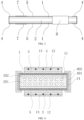
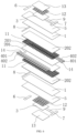
- the SOC chip has a rectangular strip structure, and includes two electrolytes 1 separated in a thickness direction.
- Inner electrode 2 is provided between the two electrolytes 1.
- Two sides of the inner electrode 2 are respectively covered by side sealing members 4.
- Outer surfaces of the electrolytes 1 are provided with outer surface elements, including intermediate layer 5, outer electrode 3, inner electrode plate 6, and outer electrode plate 7.
- the inner electrode 2 is connected to the inner electrode plate 6, and the outer electrode 3 is connected to the outer electrode plate 7.
- the side sealing members 4 each include two sub-layers, namely inner side sealing layer 401 and outer side sealing layer 402.
- the inner side sealing layer 401 and the outer side sealing layer 402 are made of materials different from those of the electrolytes 1 and the inner electrode 2.
- the outer side sealing layer 402 is dense and tight, while the inner side sealing layer 401 is rough and non-tight.
- the inner electrode and the outer electrode are provided with respective electrode plates to facilitate the connection between the SOC chip and the outside.
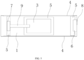
- the outer electrode plate 7 and the outer electrode 3 are connected through outer bus bar 9.
- the inner electrode 2 includes supporting inner electrode 201 and active inner electrode 202.
- the inner electrode 2 and the inner electrode plate 6 are connected through inner bus bar 8.
- An outer surface of the outer electrode 3 is provided with outer collector 12.
- the outer collector 12 and the outer electrode 3 are covered with protective layer 13.
- the inner electrode plate 6, the outer electrode plate 7, the outer electrode 3, and the outer bus bar 9 are all located on the intermediate layer 5 and do not come into direct contact with the electrolyte 1.
- the inner electrode plate 6 and the outer electrode plate 7 are arranged at a same end of the SOC chip, and the inner collector 14 is buried in the side sealing member 4.
- a preparation process of the SOC chip in the first embodiment includes the following steps.
- the structure of the SOC chip in the second embodiment is basically the same as that in the first embodiment, with the following differences.
- the intermediate layer 5 can cover an entire outer wall of the electrolyte 1 or partially cover the electrolyte 1.
- the inner electrode plate 6 connected to the inner electrode 2 and the outer electrode plate 7 connected to the outer electrode 3 are respectively arranged at two ends of the SOC chip.
- the inner bus bar 8 is located on an end surface of the SOC chip.
- the structure of the SOC chip in the third embodiment is basically the same as that in the second embodiment, with the following differences.
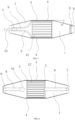
- the two ends of the SOC chip adopt a tapered design.
- a tapered edge and a straight edge of the operating surface on the hot end are at an angle ⁇ of 5-60°, preferably 10-30°.
- the temperature difference between the gas inlet or outlet of the inner electrode 2 and a central part of the outer electrode is at least 200°C.
- This design ensures a desired operating state of the SOC chip.
- the outer collector 12 is located on the outer surface of the outer electrode 3.
- Connecting piece 15 is welded on the outer electrode plate 7 for external connection.
- the connecting piece 15 is made of copper, nickel, gold, or silver.
- the structure of the SOC chip in the fourth embodiment is basically the same as that in the third embodiment, with the following differences.
- the inner bus bar 8 is located on a surface of the SOC chip, and is provided with a high-temperature end connected to the inner electrode 2 through an opening on the surface of the electrolyte 1.
- the open surface of the electrolyte 1 is further covered with sealing structure 10.
- the sealing structure 10 penetrates the electrolyte 1 and completely covers the open part of the electrolyte 1, including a junction of the inner bus bar 8 and the inner electrode 2, thus preventing the gas flowing through the inner electrode from leaking through the open part to the outside of the SOC chip.
Landscapes
- Chemical & Material Sciences (AREA)
- Engineering & Computer Science (AREA)
- Chemical Kinetics & Catalysis (AREA)
- Electrochemistry (AREA)
- Manufacturing & Machinery (AREA)
- General Chemical & Material Sciences (AREA)
- Sustainable Energy (AREA)
- Life Sciences & Earth Sciences (AREA)
- Sustainable Development (AREA)
- Materials Engineering (AREA)
- Metallurgy (AREA)
- Organic Chemistry (AREA)
- Ceramic Engineering (AREA)
- Inorganic Chemistry (AREA)
- Composite Materials (AREA)
- Fuel Cell (AREA)
- Electrolytic Production Of Non-Metals, Compounds, Apparatuses Therefor (AREA)
- Inert Electrodes (AREA)
- Hybrid Cells (AREA)
Applications Claiming Priority (2)
| Application Number | Priority Date | Filing Date | Title |
|---|---|---|---|
| CN202011337853.6A CN112467164B (zh) | 2020-11-25 | 2020-11-25 | 一种具有双电解质结构的固体氧化物电池芯片及制备方法 |
| PCT/CN2021/081647 WO2022110580A1 (zh) | 2020-11-25 | 2021-03-18 | 一种具有双电解质结构的固体氧化物电池芯片及制备方法 |
Publications (4)
| Publication Number | Publication Date |
|---|---|
| EP4243129A1 true EP4243129A1 (de) | 2023-09-13 |
| EP4243129A4 EP4243129A4 (de) | 2024-06-19 |
| EP4243129B1 EP4243129B1 (de) | 2025-04-23 |
| EP4243129C0 EP4243129C0 (de) | 2025-04-23 |
Family
ID=74799892
Family Applications (1)
| Application Number | Title | Priority Date | Filing Date |
|---|---|---|---|
| EP21896099.5A Active EP4243129B1 (de) | 2020-11-25 | 2021-03-18 | Festoxidzellenchip mit doppelelektrolytstruktur und herstellungsverfahren |
Country Status (5)
| Country | Link |
|---|---|
| US (1) | US20240014425A1 (de) |
| EP (1) | EP4243129B1 (de) |
| JP (1) | JP7565651B2 (de) |
| CN (1) | CN112467164B (de) |
| WO (1) | WO2022110580A1 (de) |
Families Citing this family (1)
| Publication number | Priority date | Publication date | Assignee | Title |
|---|---|---|---|---|
| CN112467164B (zh) * | 2020-11-25 | 2021-09-24 | 浙江臻泰能源科技有限公司 | 一种具有双电解质结构的固体氧化物电池芯片及制备方法 |
Family Cites Families (17)
| Publication number | Priority date | Publication date | Assignee | Title |
|---|---|---|---|---|
| US7222406B2 (en) * | 2002-04-26 | 2007-05-29 | Battelle Memorial Institute | Methods for making a multi-layer seal for electrochemical devices |
| US7816055B2 (en) * | 2004-03-16 | 2010-10-19 | The Regents Of The University Of California | Compact fuel cell |
| JP2006277969A (ja) * | 2005-03-28 | 2006-10-12 | Ngk Insulators Ltd | 固体電解質型燃料電池セル |
| EP2104172A1 (de) * | 2008-03-20 | 2009-09-23 | The Technical University of Denmark | Verbundglasdichtung für einen Festoxidelektrolysezellenstapel |
| JP5439160B2 (ja) * | 2009-12-24 | 2014-03-12 | 日本碍子株式会社 | 固体酸化物形燃料電池セルの製造方法、及び、同セルの分割体の成形体の製造方法 |
| WO2012008385A1 (ja) * | 2010-07-15 | 2012-01-19 | 日本碍子株式会社 | 燃料電池の構造体 |
| JP2014007061A (ja) * | 2012-06-25 | 2014-01-16 | Konica Minolta Inc | 固体酸化物型燃料電池の製造方法 |
| JP6536419B2 (ja) * | 2016-01-26 | 2019-07-03 | 株式会社デンソー | 燃料電池単セル |
| CN107959036B (zh) * | 2016-10-14 | 2021-11-30 | 浙江氢邦科技有限公司 | 一种平板型结构的固体氧化物燃料电池的制备方法 |
| CN109216740A (zh) * | 2017-07-07 | 2019-01-15 | 中国科学院宁波材料技术与工程研究所 | 一种中空对称sofc电池的阳极支撑体及其制备方法 |
| CN108336376B (zh) | 2017-12-28 | 2020-03-31 | 胡强 | 一种提高成品率和单电池功率的扁管固体氧化物电池结构及其制备方法 |
| CN108321408B (zh) | 2017-12-28 | 2020-03-31 | 胡强 | 含多对电极的扁管固体氧化物电化学器件及其制备方法 |
| CN108336386B (zh) * | 2017-12-28 | 2020-04-17 | 浙江臻泰能源科技有限公司 | 扁管结构固体氧化物电化学器件及其制备方法 |
| US20210143447A1 (en) * | 2019-11-12 | 2021-05-13 | Bryan M. Blackburn | Stack configurations for solid oxide electrochemical cells |
| CN112467164B (zh) * | 2020-11-25 | 2021-09-24 | 浙江臻泰能源科技有限公司 | 一种具有双电解质结构的固体氧化物电池芯片及制备方法 |
| CN112467165B (zh) * | 2020-11-25 | 2022-03-11 | 浙江臻泰能源科技有限公司 | 具有内嵌规律性布置气道的固体氧化物电池及制备方法 |
| CN213905412U (zh) * | 2020-11-25 | 2021-08-06 | 浙江臻泰能源科技有限公司 | 一种具有双电解质结构的固体氧化物电池芯片 |
-
2020
- 2020-11-25 CN CN202011337853.6A patent/CN112467164B/zh active Active
-
2021
- 2021-03-18 US US18/254,506 patent/US20240014425A1/en not_active Abandoned
- 2021-03-18 EP EP21896099.5A patent/EP4243129B1/de active Active
- 2021-03-18 JP JP2023551961A patent/JP7565651B2/ja active Active
- 2021-03-18 WO PCT/CN2021/081647 patent/WO2022110580A1/zh not_active Ceased
Also Published As
| Publication number | Publication date |
|---|---|
| CN112467164A (zh) | 2021-03-09 |
| US20240014425A1 (en) | 2024-01-11 |
| EP4243129B1 (de) | 2025-04-23 |
| EP4243129C0 (de) | 2025-04-23 |
| EP4243129A4 (de) | 2024-06-19 |
| JP2023550547A (ja) | 2023-12-01 |
| JP7565651B2 (ja) | 2024-10-11 |
| WO2022110580A1 (zh) | 2022-06-02 |
| CN112467164B (zh) | 2021-09-24 |
Similar Documents
| Publication | Publication Date | Title |
|---|---|---|
| Khan et al. | Flat-tubular solid oxide fuel cells and stacks: a review | |
| CN101339997B (zh) | 一种中温固体氧化物燃料电池膜电极组件及其制备 | |
| US12119526B2 (en) | Metal support for electrochemical element, electrochemical element, electrochemical module, electrochemical device, energy system, solid oxide fuel cell, solid oxide electrolytic cell, and method for manufacturing metal support | |
| CN101246980B (zh) | 固体氧化物燃料电池与热电材料联合发电系统 | |
| WO2013048705A1 (en) | Integrated natural gas powered sofc system | |
| WO2009064391A2 (en) | Electrolyte supported cell designed for longer life and higher power | |
| US11670779B2 (en) | Metal support for electrochemical element, electrochemical element, electrochemical module, electrochemical device, energy system, solid oxide fuel cell, solid oxide electrolytic cell, and method for manufacturing metal support | |
| US20230392249A1 (en) | Manufacturing Method for Alloy Material, Alloy Material, Electrochemical Element, Electrochemical Module, Electrochemical Device, Energy System and Solid Oxide Fuel Cell | |
| CN112467165B (zh) | 具有内嵌规律性布置气道的固体氧化物电池及制备方法 | |
| JP7261762B2 (ja) | 電気化学素子、電気化学モジュール、電気化学装置、エネルギーシステム、固体酸化物形燃料電池、および電気化学素子製造方法 | |
| JP7561511B2 (ja) | 電気化学素子の金属支持体、電気化学素子、電気化学モジュール、電気化学装置、エネルギーシステム、固体酸化物形燃料電池、および固体酸化物形電解セル | |
| KR102809994B1 (ko) | 전기 화학 소자의 금속 지지체, 전기 화학 소자, 전기 화학 모듈, 전기 화학 장치, 에너지 시스템, 고체 산화물 형태 연료 전지 및 금속 지지체의 제조 방법 | |
| EP4243129B1 (de) | Festoxidzellenchip mit doppelelektrolytstruktur und herstellungsverfahren | |
| KR102745793B1 (ko) | 금속지지형 전기 화학 소자용의 전극층 부착 기판, 전기 화학 소자, 전기 화학 모듈, 고체 산화물형 연료 전지, 및 제조 방법 | |
| CN108336386B (zh) | 扁管结构固体氧化物电化学器件及其制备方法 | |
| CN108321408B (zh) | 含多对电极的扁管固体氧化物电化学器件及其制备方法 | |
| Guangyao et al. | New solid state fuel cells-green power source for 21st century | |
| US20090162723A1 (en) | Integrated Single-Chamber Solid Oxide Fuel Cells | |
| JP7202060B2 (ja) | 電気化学素子、電気化学モジュール、電気化学装置、エネルギーシステム、および固体酸化物形燃料電池 | |
| CN213905412U (zh) | 一种具有双电解质结构的固体氧化物电池芯片 | |
| CN115498229B (zh) | 一种连续卷对卷水系流延制备固体氧化物电解池的方法 | |
| JP2025045901A (ja) | 固体酸化物形電解セルの製造方法 | |
| KR20160058275A (ko) | 금속지지형 고체산화물 연료전지 및 그 제조 방법 | |
| CN213905411U (zh) | 一种具有内嵌规律性布置气道的固体氧化物电池 | |
| Yano et al. | Solid oxide fuel cell with anodes using proton conductor (Barium-Cerium/Yttrium oxide) |
Legal Events
| Date | Code | Title | Description |
|---|---|---|---|
| STAA | Information on the status of an ep patent application or granted ep patent |
Free format text: STATUS: THE INTERNATIONAL PUBLICATION HAS BEEN MADE |
|
| PUAI | Public reference made under article 153(3) epc to a published international application that has entered the european phase |
Free format text: ORIGINAL CODE: 0009012 |
|
| STAA | Information on the status of an ep patent application or granted ep patent |
Free format text: STATUS: REQUEST FOR EXAMINATION WAS MADE |
|
| 17P | Request for examination filed |
Effective date: 20230605 |
|
| AK | Designated contracting states |
Kind code of ref document: A1 Designated state(s): AL AT BE BG CH CY CZ DE DK EE ES FI FR GB GR HR HU IE IS IT LI LT LU LV MC MK MT NL NO PL PT RO RS SE SI SK SM TR |
|
| DAV | Request for validation of the european patent (deleted) | ||
| DAX | Request for extension of the european patent (deleted) | ||
| A4 | Supplementary search report drawn up and despatched |
Effective date: 20240522 |
|
| RIC1 | Information provided on ipc code assigned before grant |
Ipc: H01M 8/12 20160101ALN20240515BHEP Ipc: H01M 4/86 20060101ALN20240515BHEP Ipc: H01M 8/0286 20160101ALI20240515BHEP Ipc: H01M 8/0271 20160101ALI20240515BHEP Ipc: H01M 4/88 20060101ALI20240515BHEP Ipc: H01M 8/1226 20160101ALI20240515BHEP Ipc: H01M 8/0258 20160101AFI20240515BHEP |
|
| STAA | Information on the status of an ep patent application or granted ep patent |
Free format text: STATUS: EXAMINATION IS IN PROGRESS |
|
| 17Q | First examination report despatched |
Effective date: 20240819 |
|
| REG | Reference to a national code |
Ref country code: DE Free format text: PREVIOUS MAIN CLASS: H01M0008025800 Ref country code: DE Ref legal event code: R079 Ref document number: 602021029806 Country of ref document: DE Free format text: PREVIOUS MAIN CLASS: H01M0008025800 Ipc: H01M0008027100 |
|
| GRAP | Despatch of communication of intention to grant a patent |
Free format text: ORIGINAL CODE: EPIDOSNIGR1 |
|
| STAA | Information on the status of an ep patent application or granted ep patent |
Free format text: STATUS: GRANT OF PATENT IS INTENDED |
|
| GRAJ | Information related to disapproval of communication of intention to grant by the applicant or resumption of examination proceedings by the epo deleted |
Free format text: ORIGINAL CODE: EPIDOSDIGR1 |
|
| STAA | Information on the status of an ep patent application or granted ep patent |
Free format text: STATUS: EXAMINATION IS IN PROGRESS |
|
| INTG | Intention to grant announced |
Effective date: 20250102 |
|
| RIC1 | Information provided on ipc code assigned before grant |
Ipc: H01M 8/12 20160101ALN20241213BHEP Ipc: H01M 4/86 20060101ALN20241213BHEP Ipc: H01M 8/1226 20160101ALI20241213BHEP Ipc: H01M 4/88 20060101ALI20241213BHEP Ipc: H01M 8/0286 20160101ALI20241213BHEP Ipc: H01M 8/0271 20160101AFI20241213BHEP |
|
| INTC | Intention to grant announced (deleted) | ||
| GRAP | Despatch of communication of intention to grant a patent |
Free format text: ORIGINAL CODE: EPIDOSNIGR1 |
|
| STAA | Information on the status of an ep patent application or granted ep patent |
Free format text: STATUS: GRANT OF PATENT IS INTENDED |
|
| GRAS | Grant fee paid |
Free format text: ORIGINAL CODE: EPIDOSNIGR3 |
|
| GRAA | (expected) grant |
Free format text: ORIGINAL CODE: 0009210 |
|
| STAA | Information on the status of an ep patent application or granted ep patent |
Free format text: STATUS: THE PATENT HAS BEEN GRANTED |
|
| RIC1 | Information provided on ipc code assigned before grant |
Ipc: H01M 8/12 20160101ALN20250217BHEP Ipc: H01M 4/86 20060101ALN20250217BHEP Ipc: H01M 8/1226 20160101ALI20250217BHEP Ipc: H01M 4/88 20060101ALI20250217BHEP Ipc: H01M 8/0286 20160101ALI20250217BHEP Ipc: H01M 8/0271 20160101AFI20250217BHEP |
|
| INTG | Intention to grant announced |
Effective date: 20250226 |
|
| AK | Designated contracting states |
Kind code of ref document: B1 Designated state(s): AL AT BE BG CH CY CZ DE DK EE ES FI FR GB GR HR HU IE IS IT LI LT LU LV MC MK MT NL NO PL PT RO RS SE SI SK SM TR |
|
| REG | Reference to a national code |
Ref country code: GB Ref legal event code: FG4D |
|
| REG | Reference to a national code |
Ref country code: CH Ref legal event code: EP |
|
| REG | Reference to a national code |
Ref country code: DE Ref legal event code: R096 Ref document number: 602021029806 Country of ref document: DE |
|
| REG | Reference to a national code |
Ref country code: IE Ref legal event code: FG4D |
|
| U01 | Request for unitary effect filed |
Effective date: 20250513 |
|
| U07 | Unitary effect registered |
Designated state(s): AT BE BG DE DK EE FI FR IT LT LU LV MT NL PT RO SE SI Effective date: 20250519 |
|
| PG25 | Lapsed in a contracting state [announced via postgrant information from national office to epo] |
Ref country code: ES Free format text: LAPSE BECAUSE OF FAILURE TO SUBMIT A TRANSLATION OF THE DESCRIPTION OR TO PAY THE FEE WITHIN THE PRESCRIBED TIME-LIMIT Effective date: 20250423 |
|
| PG25 | Lapsed in a contracting state [announced via postgrant information from national office to epo] |
Ref country code: NO Free format text: LAPSE BECAUSE OF FAILURE TO SUBMIT A TRANSLATION OF THE DESCRIPTION OR TO PAY THE FEE WITHIN THE PRESCRIBED TIME-LIMIT Effective date: 20250723 Ref country code: GR Free format text: LAPSE BECAUSE OF FAILURE TO SUBMIT A TRANSLATION OF THE DESCRIPTION OR TO PAY THE FEE WITHIN THE PRESCRIBED TIME-LIMIT Effective date: 20250724 |
|
| PG25 | Lapsed in a contracting state [announced via postgrant information from national office to epo] |
Ref country code: PL Free format text: LAPSE BECAUSE OF FAILURE TO SUBMIT A TRANSLATION OF THE DESCRIPTION OR TO PAY THE FEE WITHIN THE PRESCRIBED TIME-LIMIT Effective date: 20250423 |
|
| PG25 | Lapsed in a contracting state [announced via postgrant information from national office to epo] |
Ref country code: HR Free format text: LAPSE BECAUSE OF FAILURE TO SUBMIT A TRANSLATION OF THE DESCRIPTION OR TO PAY THE FEE WITHIN THE PRESCRIBED TIME-LIMIT Effective date: 20250423 |
|
| PG25 | Lapsed in a contracting state [announced via postgrant information from national office to epo] |
Ref country code: RS Free format text: LAPSE BECAUSE OF FAILURE TO SUBMIT A TRANSLATION OF THE DESCRIPTION OR TO PAY THE FEE WITHIN THE PRESCRIBED TIME-LIMIT Effective date: 20250723 |
|
| PG25 | Lapsed in a contracting state [announced via postgrant information from national office to epo] |
Ref country code: IS Free format text: LAPSE BECAUSE OF FAILURE TO SUBMIT A TRANSLATION OF THE DESCRIPTION OR TO PAY THE FEE WITHIN THE PRESCRIBED TIME-LIMIT Effective date: 20250823 |
|
| PG25 | Lapsed in a contracting state [announced via postgrant information from national office to epo] |
Ref country code: SM Free format text: LAPSE BECAUSE OF FAILURE TO SUBMIT A TRANSLATION OF THE DESCRIPTION OR TO PAY THE FEE WITHIN THE PRESCRIBED TIME-LIMIT Effective date: 20250423 |
|
| PG25 | Lapsed in a contracting state [announced via postgrant information from national office to epo] |
Ref country code: CZ Free format text: LAPSE BECAUSE OF FAILURE TO SUBMIT A TRANSLATION OF THE DESCRIPTION OR TO PAY THE FEE WITHIN THE PRESCRIBED TIME-LIMIT Effective date: 20250423 |
|
| PG25 | Lapsed in a contracting state [announced via postgrant information from national office to epo] |
Ref country code: SK Free format text: LAPSE BECAUSE OF FAILURE TO SUBMIT A TRANSLATION OF THE DESCRIPTION OR TO PAY THE FEE WITHIN THE PRESCRIBED TIME-LIMIT Effective date: 20250423 |
|
| PLBE | No opposition filed within time limit |
Free format text: ORIGINAL CODE: 0009261 |
|
| STAA | Information on the status of an ep patent application or granted ep patent |
Free format text: STATUS: NO OPPOSITION FILED WITHIN TIME LIMIT |
|
| REG | Reference to a national code |
Ref country code: CH Ref legal event code: L10 Free format text: ST27 STATUS EVENT CODE: U-0-0-L10-L00 (AS PROVIDED BY THE NATIONAL OFFICE) Effective date: 20260304 |
|
| 26N | No opposition filed |
Effective date: 20260126 |
|
| U20 | Renewal fee for the european patent with unitary effect paid |
Year of fee payment: 6 Effective date: 20260311 |