EP4239871B1 - Dreistufige wandlerschaltung sowie startverfahren und elektronische vorrichtung dafür - Google Patents
Dreistufige wandlerschaltung sowie startverfahren und elektronische vorrichtung dafür Download PDFInfo
- Publication number
- EP4239871B1 EP4239871B1 EP22211514.9A EP22211514A EP4239871B1 EP 4239871 B1 EP4239871 B1 EP 4239871B1 EP 22211514 A EP22211514 A EP 22211514A EP 4239871 B1 EP4239871 B1 EP 4239871B1
- Authority
- EP
- European Patent Office
- Prior art keywords
- capacitor
- switch
- relay
- turning
- soft
- Prior art date
- Legal status (The legal status is an assumption and is not a legal conclusion. Google has not performed a legal analysis and makes no representation as to the accuracy of the status listed.)
- Active
Links
Images


Classifications
-
- H—ELECTRICITY
- H02—GENERATION; CONVERSION OR DISTRIBUTION OF ELECTRIC POWER
- H02M—APPARATUS FOR CONVERSION BETWEEN AC AND AC, BETWEEN AC AND DC, OR BETWEEN DC AND DC, AND FOR USE WITH MAINS OR SIMILAR POWER SUPPLY SYSTEMS; CONVERSION OF DC OR AC INPUT POWER INTO SURGE OUTPUT POWER; CONTROL OR REGULATION THEREOF
- H02M3/00—Conversion of DC power input into DC power output
- H02M3/02—Conversion of DC power input into DC power output without intermediate conversion into AC
- H02M3/04—Conversion of DC power input into DC power output without intermediate conversion into AC by static converters
- H02M3/10—Conversion of DC power input into DC power output without intermediate conversion into AC by static converters using discharge tubes with control electrode or semiconductor devices with control electrode
- H02M3/145—Conversion of DC power input into DC power output without intermediate conversion into AC by static converters using discharge tubes with control electrode or semiconductor devices with control electrode using devices of a triode or transistor type requiring continuous application of a control signal
- H02M3/155—Conversion of DC power input into DC power output without intermediate conversion into AC by static converters using discharge tubes with control electrode or semiconductor devices with control electrode using devices of a triode or transistor type requiring continuous application of a control signal using semiconductor devices only
- H02M3/156—Conversion of DC power input into DC power output without intermediate conversion into AC by static converters using discharge tubes with control electrode or semiconductor devices with control electrode using devices of a triode or transistor type requiring continuous application of a control signal using semiconductor devices only with automatic control of output voltage or current, e.g. switching regulators
-
- H—ELECTRICITY
- H02—GENERATION; CONVERSION OR DISTRIBUTION OF ELECTRIC POWER
- H02M—APPARATUS FOR CONVERSION BETWEEN AC AND AC, BETWEEN AC AND DC, OR BETWEEN DC AND DC, AND FOR USE WITH MAINS OR SIMILAR POWER SUPPLY SYSTEMS; CONVERSION OF DC OR AC INPUT POWER INTO SURGE OUTPUT POWER; CONTROL OR REGULATION THEREOF
- H02M1/00—Details of apparatus for conversion
- H02M1/36—Means for starting or stopping converters
-
- H—ELECTRICITY
- H02—GENERATION; CONVERSION OR DISTRIBUTION OF ELECTRIC POWER
- H02M—APPARATUS FOR CONVERSION BETWEEN AC AND AC, BETWEEN AC AND DC, OR BETWEEN DC AND DC, AND FOR USE WITH MAINS OR SIMILAR POWER SUPPLY SYSTEMS; CONVERSION OF DC OR AC INPUT POWER INTO SURGE OUTPUT POWER; CONTROL OR REGULATION THEREOF
- H02M3/00—Conversion of DC power input into DC power output
- H02M3/02—Conversion of DC power input into DC power output without intermediate conversion into AC
- H02M3/04—Conversion of DC power input into DC power output without intermediate conversion into AC by static converters
- H02M3/06—Conversion of DC power input into DC power output without intermediate conversion into AC by static converters using resistors or capacitors, e.g. potential divider
-
- H—ELECTRICITY
- H02—GENERATION; CONVERSION OR DISTRIBUTION OF ELECTRIC POWER
- H02M—APPARATUS FOR CONVERSION BETWEEN AC AND AC, BETWEEN AC AND DC, OR BETWEEN DC AND DC, AND FOR USE WITH MAINS OR SIMILAR POWER SUPPLY SYSTEMS; CONVERSION OF DC OR AC INPUT POWER INTO SURGE OUTPUT POWER; CONTROL OR REGULATION THEREOF
- H02M3/00—Conversion of DC power input into DC power output
- H02M3/02—Conversion of DC power input into DC power output without intermediate conversion into AC
- H02M3/04—Conversion of DC power input into DC power output without intermediate conversion into AC by static converters
- H02M3/10—Conversion of DC power input into DC power output without intermediate conversion into AC by static converters using discharge tubes with control electrode or semiconductor devices with control electrode
- H02M3/145—Conversion of DC power input into DC power output without intermediate conversion into AC by static converters using discharge tubes with control electrode or semiconductor devices with control electrode using devices of a triode or transistor type requiring continuous application of a control signal
- H02M3/155—Conversion of DC power input into DC power output without intermediate conversion into AC by static converters using discharge tubes with control electrode or semiconductor devices with control electrode using devices of a triode or transistor type requiring continuous application of a control signal using semiconductor devices only
- H02M3/156—Conversion of DC power input into DC power output without intermediate conversion into AC by static converters using discharge tubes with control electrode or semiconductor devices with control electrode using devices of a triode or transistor type requiring continuous application of a control signal using semiconductor devices only with automatic control of output voltage or current, e.g. switching regulators
- H02M3/158—Conversion of DC power input into DC power output without intermediate conversion into AC by static converters using discharge tubes with control electrode or semiconductor devices with control electrode using devices of a triode or transistor type requiring continuous application of a control signal using semiconductor devices only with automatic control of output voltage or current, e.g. switching regulators including plural semiconductor devices as final control devices for a single load
- H02M3/1582—Buck-boost converters
-
- H—ELECTRICITY
- H02—GENERATION; CONVERSION OR DISTRIBUTION OF ELECTRIC POWER
- H02M—APPARATUS FOR CONVERSION BETWEEN AC AND AC, BETWEEN AC AND DC, OR BETWEEN DC AND DC, AND FOR USE WITH MAINS OR SIMILAR POWER SUPPLY SYSTEMS; CONVERSION OF DC OR AC INPUT POWER INTO SURGE OUTPUT POWER; CONTROL OR REGULATION THEREOF
- H02M7/00—Conversion of AC power input into DC power output; Conversion of DC power input into AC power output
- H02M7/42—Conversion of DC power input into AC power output without possibility of reversal
- H02M7/44—Conversion of DC power input into AC power output without possibility of reversal by static converters
- H02M7/48—Conversion of DC power input into AC power output without possibility of reversal by static converters using discharge tubes with control electrode or semiconductor devices with control electrode
- H02M7/483—Converters with outputs that each can have more than two voltages levels
- H02M7/4837—Flying capacitor converters
Definitions
- Embodiments of the present invention relate to the technical field of power electronics, and in particular, relate to a three-level converting circuit, and a starting method and electronic device thereof.
- the inventor found that there was at least the following problem in the above related technologies: during the starting of the three-level converter with the flying capacitor, some switch devices risk overvoltage if the flying capacitor is not charged in advance.
- the solution of adding a charging circuit requires a certain dynamic response time for the charging circuit, and the switch devices still risk overvoltage, and the whole circuit is complicated and the cost is high.
- the solution of directly adding a passive device to the main circuit solves the risk of overvoltage of the devices, it brings new problems such as unbalanced bus voltage.
- JP2021175260A discloses a DC/DC conversion device in which a flying capacitor can be safely pre-charged.
- a low-voltage side capacitor C3 is connected in parallel with a low-voltage side DC power source 1.
- a high-voltage side capacitor C4 is connected in parallel with a high-voltage side DC power source 2.
- a flying capacitor part 30 includes a plurality of switching elements which are connected in series, and at least one flying capacitor.
- the high-voltage side DC power source 2 is connected to both ends of the plurality of switching elements which are connected in series, and the low-voltage side DC power source 1 is connected to both ends of a part of the plurality of switching elements constituting the plurality of switching elements which are connected in series.
- At least one of reactors L1, L2 are interposed on a path between both ends of the low-voltage side capacitor C3 and both ends of the part of switching elements.
- a switch circuit 50 is interposed on a path between the high-voltage side capacitor C4 and the high-voltage side DC power source 2.
- CN208174548U discloses a two -way LLC direct -current converter based on three level structures of half -bridge, the operation of circuit forward, power V1 side switch tube S1, S2, S3, S4 normally works, the four ways drive is all adopted and is fixed 0.5 duty cycle, switch tube S1 and the complementation of switch tube S4 switch on, switch tube S2 and the complementation of switch tube S3 switch on, power V2 side switch tube S5, S6, S7, S8 is all at the blocked state, only the transmission course of energy is participated in to body diode, when two -way LLC converter is taken to transfer duty ratio control, only need to change the phase angle that moves between S1, S2 and S3, the S4, when taking frequency modulation control, only need to change switching frequency.
- CN102916603A discloses a single-phase unsymmetrical multi-level inverter with a pre-charging circuit and a charging method of the single-phase unsymmetrical multi-level inverter, belonging to the field of electric energy conversion.
- the single-phase unsymmetrical multi-level inverter is used for converting direct current to alternating current.
- the single-phase unsymmetrical multi-level inverter comprises a switch, a charging resistor, ten power switch elements and three capacitors, wherein the selector switch is connected in parallel with the charging resistor and then connected in series between a direct current input power source and the direct current anode of the single-phase unsymmetrical multi-level inverter.
- the selector switch is cut off, the direct current input power source charges the two serial capacitors at a direct current input end through the charging resistor; after the two serial capacitors are charged, the voltage of a suspension capacitor is acquired, and the two power switch elements which are used for connecting the suspension capacitor and an anode busbar of the inverter are conducted with the two power switch elements which are used for connecting the suspension capacitor and the cathode busbar of the inverter; and when the voltage of the suspension capacitor is equal to 1/4 of the voltage of a direct current power source, the conducted power switch elements are cut off, and the selector switch is closed.
- Embodiments of the present application provide a three-level converting circuit, and a starting method and electronic device thereof.
- embodiments of the present invention provide a three-level converting circuit, and a starting method and electronic device thereof, and the circuit includes: a first voltage source; a first soft-start circuit; a first capacitor; a first switch, a second switch, a third switch and a fourth switch sequentially connected in series; a flying capacitor; a second soft-start circuit; a second voltage source and a second capacitor.
- the three-level converting circuit provided according to the embodiments of the present invention can pre-charge the flying capacitor, the first capacitor and the second capacitor when executing the starting method thereof, thereby preventing the over-voltage damage of the switches.
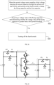
- FIG. 1 shows a circuit diagram of a three-level converting circuit provided according to the embodiment of the present invention
- the three-level converting circuit includes: a first voltage source V1; a first soft-start circuit 110; a first capacitor C1; a first switch S1, a second switch S2, a third switch S3 and a fourth switch S4 sequentially connected in series; a flying capacitor Cf; a second soft-start circuit 120; an inductor L; a second voltage source V2; and a second capacitor C2.
- the first voltage source V1 When the first voltage source V1 is used as the input voltage side, a high voltage is input, and the high voltage is at least a high voltage relative to the rated voltage of a switch (i.e., any of the first switch S1, the second switch S2, the third switch S3 and the fourth switch S4 with the same specifications; which applies equally to the following description), and at this time, the first voltage source V1 can output DC power.
- a switch i.e., any of the first switch S1, the second switch S2, the third switch S3 and the fourth switch S4 with the same specifications; which applies equally to the following description
- the first soft-start circuit 110 has a first terminal connected to a positive terminal of the first voltage source V1; the first soft-start circuit 110 can charge the first capacitor C1 and the flying capacitor Cf at the starting stage of the three-level converting circuit when the first voltage source V1 supplies a high voltage, thereby realizing soft-start, and preventing excessive current impact when the first voltage source V1 charges the first capacitor C1 and the flying capacitor Cf.
- the first soft-start circuit 110 includes a first relay RY1, a first resistor R1 and a second relay RY2, and the first relay RY1 is connected in series with the first resistor R1 and then connected in parallel with the second relay RY2.
- the series branch of the first relay RY1 and the first resistor R1 is turned on to realize soft-start.
- the branch of the second relay RY2 is turned on to realize the normal operation of the three-level converting circuit.
- the first resistor R1 is a soft-start resistor.
- the first relay RY1 and the second relay RY2 are normally-open relays.
- the first capacitor C1 is connected between a second terminal of the first soft-start circuit 110 and a negative terminal of the first voltage source V1, and the first capacitor C1 is used for filtering.
- the first switch S1, the second switch S2, the third switch S3 and the fourth switch S4 are sequentially connected in series. Specifically, an emitter of the first switch S1 is connected to a collector of the second switch S2, an emitter of the second switch S2 is connected to a collector of the third switch S3, and an emitter of the third switch S3 is connected to a collector of the fourth switch S4. Furthermore, a collector of the first switch S1 is connected to a second terminal of the first soft-start circuit 110, and an emitter of the fourth switch S4 is connected to a negative terminal of the first voltage source V1.
- the flying capacitor Cf is connected between the collector of the second switch S2 and the emitter of the third switch S3.
- the flying capacitor Cf is used to store energy and transfer it to a DC port (i.e., the first voltage source V1 port or the second voltage source V2 port, which applies equally to the following description).
- the introduction of the flying capacitor Cf can improve the common-mode characteristic of the circuit, and realize the frequency doubling effect of inductor current ripple or the like.
- the second soft-start circuit 120 has a first terminal connected to the emitter of the second switch transistor S2 and connected to the collector of the third switch transistor S3.
- the second soft-start circuit 120 can charge the second capacitor C2 and the flying capacitor Cf at the starting stage of the three-level converting circuit when the second voltage source V2 supplies a high voltage, thereby realizing soft-start, and preventing excessive current impact when the second voltage source V2 charges the second capacitor C2 and the flying capacitor Cf.
- the second soft-start circuit 120 includes a third relay RY3, a second resistor R2 and a fourth relay RY4, and the third relay RY3 is connected in series with the second resistor R2 and then connected in parallel with the fourth relay RY4.
- the series branch of the third relay RY3 and the second resistor R2 is turned on to realize soft-start.
- the branch of the fourth relay RY4 is turned on to realize the normal operation of the three-level converting circuit.
- the third relay RY3 and the fourth relay RY4 are normally-open relays.
- a positive terminal of the second voltage source V2 is connected to a second terminal of the second soft-start circuit 120.
- the second voltage source V2 When the second voltage source V2 is used as the input voltage side, a high voltage is input, and the high voltage is at least a high voltage relative to the rated voltage of the switch. At this time, the second voltage source V2 can output a DC power.
- the second capacitor C2 is connected between a first terminal of the second soft-start circuit 120 and a negative terminal of the second voltage source V2, and the second capacitor C2 is used for filtering.
- the inductor L is connected between the emitter of the second switch S2 and the first terminal of the second soft-start circuit 120, and the inductor L is used for energy storage.
- the three-level converting circuit provided according to the embodiment of the present invention shares the switch with the main circuit to provide a charging branch, and is used in cooperation with the relay in the soft-start circuit, so as to pre-charge the flying capacitor in the soft-start process. Meanwhile, the DC port can also prevent excessive current impact through the soft-start circuit, thereby saving the space and cost of the equipment or module.
- This embodiment of the present invention provides a starting method of a three-level converting circuit, and the starting method can be applied to the three-level converting circuit described in the first embodiment.
- FIG. 2 which shows a flowchart diagram of a starting method of the three-level converting circuit provided according to the embodiment of the present invention
- the starting method of the three-level converting circuit includes, but not limited to, the following steps:
- Step S11 when the first voltage source supplies a high voltage, charging the first capacitor through the first soft-start circuit, and turning on the first switch and the fourth switch to charge the flying capacitor.
- the step of charging the first capacitor through the first soft-start circuit includes: turning on the first relay and turning off the second relay, so that the first voltage source supplies power to the first capacitor through the first resistor.
- FIG. 3 is a diagram illustrating the working principle of the three-level converting circuit shown in FIG. 1 under the starting method provided according to the embodiment of the present invention.
- the direction of the dotted arrow in FIG. 3 indicates the flow direction of the operating current.
- the first switch S1 and the fourth switch S4 are firstly turned on, and then the first relay RY1 is turned on, so that the first capacitor C1 and the flying capacitor Cf are charged simultaneously. Due to the first resistor R1, the voltages of the first capacitor C1 and the flying capacitor Cf may rise slowly.
- Step S12 acquiring a voltage value of the flying capacitor, and determining whether the voltage value of the flying capacitor is greater than a first preset threshold; if so, proceeding to step S13.
- the flying capacitor when it is detected that the voltage of the flying capacitor reaches the first preset threshold, the flying capacitor has a certain voltage at this time, and the first switch has no risk of overvoltage. Then, the method may proceed to step S13 to turn off the first switch and the fourth switch.
- the first preset threshold may be set according to the selection of the switches and the specific connection of the circuit in practical application, and for example, it may be set to be half of the first voltage source.
- Step S13 turning off the first switch and the fourth switch.
- the first relay is kept in an ON state so that the first voltage source continues to charge the first capacitor through the first resistor, thereby realizing soft-start.
- FIG. 4 shows a flowchart diagram of a starting method of another three-level converting circuit provided according to the embodiment of the present invention, the method further includes the following steps:
- the second preset threshold is set to be a value larger than the first preset threshold, and specifically, it may be set according to actual needs.
- This embodiment of the present invention provides a starting method of a three-level converting circuit, and the starting method can be applied to the three-level converting circuit described in the first embodiment.
- FIG. 5 which shows a flowchart diagram of a starting method of a three-level converting circuit provided according to the embodiment of the present invention
- the starting method of the three-level converting circuit includes, but not limited to, the following steps: Step S21: when the first voltage source supplies a high voltage, charging the first capacitor through the first soft-start circuit, and turning on the first switch to charge the flying capacitor and the second capacitor.
- the step of charging the first capacitor through the first soft-start circuit includes: turning on the first relay and turning off the second relay, so that the first voltage source supplies power to the first capacitor through the first resistor.
- FIG. 6 is a diagram illustrating the working principle of the three-level converting circuit shown in FIG. 1 under the starting method provided according to the embodiment of the present invention.
- the direction of the dotted arrow in FIG. 6 indicates the flow direction of the operating current.
- the first voltage source V1 supplies a high voltage
- the first switch S1 is firstly turned on, and then the first relay RY1 is turned on, and the flying capacitor Cf and the second capacitor C2 form a series branch through the free-wheel diodes of the first switch S1 and the third switch S3.
- the first capacitor C1 and the flying capacitor Cf can also be charged simultaneously, and furthermore, the second capacitor C2 can be charged. Due to the first resistor R1, the voltages of the first capacitor C1 and the flying capacitor Cf may rise slowly.
- Step S22 acquiring a voltage value of the flying capacitor, and determining whether the voltage value of the flying capacitor is greater than a first preset threshold; if so, proceeding to the step S23.
- the flying capacitor when it is detected that the voltage of the flying capacitor reaches the first preset threshold, the flying capacitor has a certain voltage at this time, and the first switch has no risk of overvoltage. Then, the method may proceed to step S23 to turn off the first switch.
- the first preset threshold may be set according to the selection of the switches and the specific connection of the circuit in practical application, and for example, it may be set to be half of the first voltage source.
- Step S23 turning off the first switch.
- the first relay is kept in an ON state so that the first voltage source continues to charge the first capacitor through the first resistor, thereby realizing soft-start.
- FIG. 7 shows a flowchart diagram of a starting method of another three-level converting circuit provided according to the embodiment of the present invention, the method further includes the following steps:
- the second preset threshold is set to be a value larger than the first preset threshold, and specifically, it may be set according to actual needs.
- This embodiment of the present invention provides a starting method of a three-level converting circuit, and the starting method can be applied to the three-level converting circuit described in the first embodiment.
- the starting method of the three-level converting circuit includes, but not limited to, the following steps: Step S31: when the second voltage source supplies a high voltage, charging the second capacitor through the second soft-start circuit, and turning on the fourth switch to charge the flying capacitor and the first capacitor.
- the step of charging the second capacitor through the second soft-start circuit includes: turning on the third relay in the second soft-start circuit and turning off the fourth relay, so that the second voltage source supplies power to the second capacitor through the second resistor.
- FIG. 9 is a diagram illustrating the working principle of the three-level converting circuit shown in FIG. 1 under the starting method provided according to the embodiment of the present invention.
- the direction of the dotted arrow in FIG. 9 indicates the flow direction of the operating current.
- the fourth switch S4 when the second voltage source V2 supplies a high voltage, the fourth switch S4 is firstly turned on, and then the third relay RY3 is turned on, and the flying capacitor Cf, the first capacitor C1 and the second capacitor C2 form a series branch through the free-wheel diode of the first switch S1, the free-wheel diode of the second switch S2, and the fourth switch S4 so that the first capacitor C1, the second capacitor C2 and the flying capacitor Cf are charged simultaneously. Due to the second resistor R2, the voltages of the first capacitor C1, the second capacitor C2 and the flying capacitor Cf may rise slowly.
- Step S32 acquiring a voltage value of the flying capacitor, and determining whether the voltage value of the flying capacitor is greater than a third preset threshold; if so, proceeding to step S33.
- the flying capacitor when it is detected that the voltage of the flying capacitor reaches the third preset threshold, the flying capacitor has a certain voltage at this time, and the fourth switch has no risk of overvoltage. Then, the method may proceed to step S33 to turn off the fourth switch.
- the third preset threshold may be set according to the selection of the switches and the specific connection of the circuit in practical application, and for example, it may be set to be half of the second voltage source.
- Step S33 turning off the fourth switch.
- the third relay is kept in an ON state so that the second voltage source continues to charge the second capacitor through the second resistor, thereby realizing soft-start.
- FIG. 10 shows a flowchart diagram of a starting method of another three-level converting circuit provided according to the embodiment of the present invention, the method further includes steps of:
- the fourth preset threshold is set to be a value larger than the third preset threshold, and specifically, it may be set according to actual needs.
- FIG. 11 shows the hardware structure of an electronic device 10 capable of executing the starting method described in the second embodiment, the third embodiment or the fourth embodiment.
- the electronic device 10 includes: at least one processor 11; and a memory 12 communicatively connected to the at least one processor 11.
- One processor 11 is taken as an example in FIG. 11 .
- the processor 11 may be connected to the first switch S1, the second switch S2, the third switch S3, the fourth switch S4, the first soft-start circuit 110 and the second soft-start circuit 120 in the three-level converting circuit described in the first embodiment, and it may control the switch devices to be turned on by outputting a driving signal from the driving module.
- the process 11 may also be connected to the first relay RY1, the second relay RY2, the third relay RY3 and the fourth relay RY4.
- the memory 12 stores instructions that can be executed by the at least one processor 11, and the instructions are executed by the at least one processor 11 to enable the at least one processor 11 to execute the starting method described above in FIG. 2 to FIG. 10 .
- the processor 11 and the memory 12 may be connected by a bus or by other means, and the connection by a bus is taken as an example in FIG. 11 .
- the memory 12 may be used to store nonvolatile software programs, nonvolatile computer executable programs and modules, such as program instructions/modules corresponding to the starting methods in the embodiments of the present application.
- the processor 11 executes various functional applications and data processing of the electronic device 10, i.e., implement the starting method provided by the above embodiments of the method, by running the nonvolatile software programs, instructions and modules stored in the memory 12.
- the memory 12 may include a program storage area and a data storage area, wherein the program storage area may store operating systems and application programs required by at least one function; and the data storage area may store data created according to the use of the starting device or the like.
- the memory 12 may include a high-speed random access memory, and may also include a nonvolatile memory, such as at least one magnetic disk memory device, flash memory device, or other nonvolatile solid-state memory device.
- the memory 12 optionally includes memories remotely provided relative to the processor 11, and these remote memories may be connected to the starting device through a network. Examples of the above network include, but not limited to, the Internet, Intranet, local area networks, mobile communication networks and combinations thereof.
- the one or more modules are stored in the memory 12, and when executed by the one or more processors 11, the one or more modules execute the starting method in any of the embodiments of the methods described above, e.g., execute the steps of the methods of FIG. 2 to FIG. 10 described above.
- An embodiment of the present application further provides a nonvolatile computer readable storage medium, in which computer executable instructions are stored.
- the computer executable instructions are executed by one or more processors to execute the steps of the methods of FIG. 2 to FIG. 10 described above.
- An embodiment of the present application further provides a computer program product, which includes a computer program stored on a nonvolatile computer readable storage medium.
- the computer program includes program instructions which, when executed by a computer, enable the computer to execute the starting method in any of the embodiments of the methods described above, e.g., execute the steps of the methods of FIG. 2 to FIG. 10 described above.
- Embodiments of the present invention provide a three-level converting circuit, and a starting method and electronic device thereof.
- the circuit includes: a first voltage source; a first soft-start circuit; a first capacitor; a first switch, a second switch, a third switch and a fourth switch sequentially connected in series; a flying capacitor; a second soft-start circuit; a second voltage source and a second capacitor.
- the three-level converting circuit provided according to the embodiments of the present invention can pre-charge the flying capacitor, the first capacitor and the second capacitor when executing the starting method thereof, thereby preventing the over-voltage damage of the switches.
- each embodiment may be realized by means of software plus a general hardware platform, and of course, it may also be realized by hardware.
- the implementation of all or part of the processes in the embodiments of the methods described above may be completed by instructing related hardware through a computer program, and the program may be stored in a computer readable storage medium. When it is executed, the program may include the processes of the embodiments of the methods described above.
- the storage medium may be a magnetic disk, an optical disk, a Read-Only Memory (ROM) or a Random Access Memory (RAM) or the like.
Landscapes
- Engineering & Computer Science (AREA)
- Power Engineering (AREA)
- Direct Current Feeding And Distribution (AREA)
- Dc-Dc Converters (AREA)
Claims (7)
- Anlaufverfahren der dreistufigen Umwandlungsschaltung, wobei die dreistufige Umwandlungsschaltung eine erste Spannungsquelle (V1), eine erste Softanlaufschaltung (110), einen ersten Kondensator (C1), einen ersten Schalter (S1), einen zweiten Schalter (S2), einen dritten Schalter (S3), einen vierten Schalter (S4), einen fliegenden Kondensator (Cf), eine zweite Softanlaufschaltung (120), einen Induktor (L), eine zweite Spannungsquelle (V2) und einen zweiten Kondensator (C2) umfasst;wobei eine Plusklemme der ersten Spannungsquelle (V1) mit einer ersten Klemme der ersten Softanlaufschaltung (110) verbunden ist, der erste Kondensator (C1) zwischen einer zweiten Klemme der ersten Softanlaufschaltung (110) und einer Minusklemme der ersten Spannungsquelle (V1) verbunden ist, eine Plusklemme der zweiten Spannungsquelle (V2) mit einer zweiten Klemme der zweiten Softanlaufschaltung (120) verbunden ist, der zweite Kondensator (C2) zwischen der ersten Klemme der zweiten Softanlaufschaltung (120) und einer Minusklemme der zweiten Spannungsquelle (V2) verbunden ist;wobei ein Emitter des ersten Schalters (S1) mit einem Kollektor des zweiten Schalters (S2) verbunden ist, ein Emitter des zweiten Schalters (S2) mit einem Kollektor des dritten Schalters (S3) verbunden ist, ein Emitter des dritten Schalters (S3) mit einem Kollektor des vierten Schalters (S4) verbunden ist, ein Kollektor des ersten Schalters (S 1) mit der zweiten Klemme der ersten Softanlaufschaltung (110) verbunden ist, ein Emitter des vierten Schalters (S4) mit der Minusklemme der ersten Spannungsquelle (V1) verbunden ist, der fliegende Kondensator (Cf) zwischen einem Kollektor des zweiten Schalters (S2) und einem Emitter des dritten Schalters (S3) verbunden ist, der Induktor (L) zwischen einem Emitter des zweiten Schalters (S2) und einer ersten Klemme der zweiten Softanlaufschaltung (120) verbunden ist;wobei die zweite Softanlaufschaltung ein drittes Relais (RY3), einen zweiten Widerstand und ein viertes Relais (RY4) umfasst;wobei das dritte Relais (RY3) in Reihe mit dem zweiten Widerstand (R2) geschaltet ist und dann mit dem vierten Relais (RY4) parallel geschaltet ist, das dritte Relais (RY3) und das vierten Relais (RY4) normalerweise offene Relais sind;dadurch gekennzeichnet, dass, wenn die zweite Spannungsquelle (V2) eine Hochspannung liefert, das Anlaufverfahren Folgendes umfasst:Einschalten des dritten Relais (RY3) in der zweiten Softanlaufschaltung (120) und Ausschalten des vierten Relais (RY4), so dass die zweite Spannungsquelle (V2) den zweiten Kondensator (C2) über den zweiten Widerstand (R2) mit Strom versorgt,Einschalten des vierten Schalters (S4), um den fliegenden Kondensator (Cf) und den ersten Kondensator (C1) zu laden;wenn der vierte Schalter (S4) und das dritte Relais (RY3) beide eingeschaltet sind, der fliegende Kondensator (Cf), der erste Kondensator (C1) und der zweite Kondensator (C2) durch eine Freilaufdiode des ersten Schalters (S1), eine Freilaufdiode des zweiten Schalters (S2) und den vierten Schalter (S4) einen seriellen Zweig bilden, um den ersten Kondensator (C1), den zweiten Kondensator (C2) und den fliegenden Kondensator (Cf) gleichzeitig zu laden;Erheben eines Spannungswerts des fliegenden Kondensators (Cf) und Bestimmen, ob der Spannungswert des fliegenden Kondensators (Cf) größer als ein dritter voreingestellter Schwellenwert ist; als Reaktion darauf, dass der Spannungswert des fliegenden Kondensators (Cf) größer als ein dritter voreingestellter Schwellenwert ist, der vierte Schalter (S4) ausgeschaltet wird.
- Verfahren nach Anspruch 1, dadurch gekennzeichnet, dass die erste Softanlaufschaltung ein erstes Relais (RY1), einen ersten Widerstand (R1) und ein zweites Relais (RY2) umfasst;wobei das erste Relais (RY1) in Reihe mit dem ersten Widerstand (R1) und dann mit dem zweiten Relais (RY2) parallel geschaltet wird; das erste Relais (RY1) und das zweite Relais (RY2) normalerweise offene Relais sind;wobei, wenn die erste Spannungsquelle (V1) eine Hochspannung liefert, das Anlaufverfahren Folgendes umfasst:Einschalten des ersten Relais und Ausschalten des zweiten Relais (RY2), so dass die erste Spannungsquelle (V1) den ersten Kondensator (C1) durch den ersten Widerstand (R1) mit Strom versorgtEinschalten des ersten Schalters (S1) und des vierten Schalters (S4), um den fliegenden Kondensator (Cf) zu laden;Erheben eines Spannungswerts des fliegenden Kondensators (Cf) und Bestimmen, ob der Spannungswert des fliegenden Kondensators (Cf) größer als ein erster voreingestellter Schwellenwert ist;als Reaktion darauf, dass der Spannungswert des fliegenden Kondensators (Cf) größer als der erste voreingestellte Schwellenwert ist, der erste Schalter (S1) und der vierte Schalter (S4) ausgeschaltet werden.
- Verfahren nach Anspruch 2, dadurch gekennzeichnet, dass das Verfahren ferner Folgendes umfasst:Erheben eines Spannungswerts des ersten Kondensators (C1) und Bestimmen, ob der Spannungswert des ersten Kondensators (C1) größer als ein zweiter voreingestellter Schwellenwert ist;als Reaktion darauf, dass der Spannungswert des ersten Kondensators (C1) größer als der zweite voreingestellte Schwellenwert ist, Ausschalten des ersten Relais (RY1) und Einschalten des zweiten Relais (RY2).
- Verfahren nach Anspruch 1, dadurch gekennzeichnet, dass die erste Softanlaufschaltung ein erstes Relais (RY1), einen ersten Widerstand (R1) und ein zweites Relais (RY2) umfasst;wobei das erste Relais (RY1) in Reihe mit dem ersten Widerstand (R1) und dann mit dem zweiten Relais (RY2) parallel geschaltet wird; das erste Relais (RY1) und das zweite Relais (RY2) normalerweise offene Relais sind;wenn die erste Spannungsquelle (V1) eine Hochspannung liefert, das Anlaufverfahren Folgendes umfasst:Einschalten des ersten Relais (RY1) und Ausschalten des zweiten Relais (RY2), so dass die erste Spannungsquelle (V1) den ersten Kondensator (C1) über den ersten Widerstand (R1) mit Strom versorgt;Einschalten des ersten Schalters (S1), so dass der fliegende Kondensator (Cf) und der zweite Kondensator (C2) durch Freilaufdioden des ersten Schalters (S1) und des dritten Schalters (S3) einen Serienzweig bilden, um den fliegenden Kondensator (Cf) und den zweiten Kondensator (S2) aufzuladen;Erheben eines Spannungswerts des fliegenden Kondensators (Cf) und Bestimmen, ob der Spannungswert des fliegenden Kondensators (Cf) größer als ein erster voreingestellter Schwellenwert ist;als Reaktion darauf, dass der Spannungswert des fliegenden Kondensators (Cf) größer als der erste voreingestellte Schwellenwert ist, Ausschalten des ersten Schalters (S1).
- Verfahren nach Anspruch 4, dadurch gekennzeichnet, dass das Verfahren ferner Folgendes umfasst:Erheben eines Spannungswerts des ersten Kondensators (C1) und Bestimmen, ob der Spannungswert des ersten Kondensators (C1) größer als ein zweiter voreingestellter Schwellenwert ist;Als Reaktion darauf, dass der Spannungswert des ersten Kondensators (C1) größer als der zweite voreingestellte Schwellenwert ist, Ausschalten des ersten Relais (RY1) und Einschalten des zweiten Relais (RY2).
- Verfahren nach Anspruch 1, dadurch gekennzeichnet, dass das Verfahren ferner Folgendes umfasst:Erheben eines Spannungswerts des zweiten Kondensators (C2) und Bestimmen, ob der Spannungswert des zweiten Kondensators (C2) größer als ein vierter voreingestellter Schwellenwert ist;als Reaktion darauf, dass der Spannungswert des ersten Kondensators (C1) größer als der zweite voreingestellte Schwellenwert ist, Ausschalten des dritten Relais (RY3) und Einschalten des vierten Relais (RY4).
- Elektronische Vorrichtung (10), dadurch gekennzeichnet, dass sie Folgendes umfasst:mindestens einen Prozessor (11); undeinen Speicher (12), der kommunikativ mit dem mindestens einen Prozessor (11) verbunden ist; wobeider Speicher (12) Anweisungen speichert, die von mindestens einem Prozessor (11) ausgeführt werden können, und die Anweisungen, wenn sie von dem mindestens einen Prozessor (11) ausgeführt werden, es dem mindestens einem Prozessor (11) ermöglichen, das Verfahren nach einem der Ansprüche 1 bis 6 auszuführen.
Applications Claiming Priority (1)
| Application Number | Priority Date | Filing Date | Title |
|---|---|---|---|
| CN202210203225.1A CN114268220B (zh) | 2022-03-03 | 2022-03-03 | 一种三电平变换电路及其启动方法、电子设备 |
Publications (3)
| Publication Number | Publication Date |
|---|---|
| EP4239871A1 EP4239871A1 (de) | 2023-09-06 |
| EP4239871C0 EP4239871C0 (de) | 2024-11-06 |
| EP4239871B1 true EP4239871B1 (de) | 2024-11-06 |
Family
ID=80834011
Family Applications (1)
| Application Number | Title | Priority Date | Filing Date |
|---|---|---|---|
| EP22211514.9A Active EP4239871B1 (de) | 2022-03-03 | 2022-12-05 | Dreistufige wandlerschaltung sowie startverfahren und elektronische vorrichtung dafür |
Country Status (4)
| Country | Link |
|---|---|
| US (1) | US11791717B2 (de) |
| EP (1) | EP4239871B1 (de) |
| CN (1) | CN114268220B (de) |
| PL (1) | PL4239871T3 (de) |
Families Citing this family (4)
| Publication number | Priority date | Publication date | Assignee | Title |
|---|---|---|---|---|
| CN115102382B (zh) * | 2022-07-28 | 2026-04-14 | 科华数据股份有限公司 | 变压电路电容缓充方法及设备、变压系统 |
| CN115912884B (zh) * | 2022-10-26 | 2024-05-28 | 深圳迈格瑞能技术有限公司 | 一种软启动控制电路及方法 |
| CN117691849B (zh) * | 2023-11-02 | 2024-11-22 | 深圳市极测科技有限公司 | 充电方法、充电装置和存储介质 |
| CN119865036A (zh) * | 2025-01-15 | 2025-04-22 | 广东恒翼能科技股份有限公司 | 一种dc三电平飞跨电容预充电系统 |
Family Cites Families (12)
| Publication number | Priority date | Publication date | Assignee | Title |
|---|---|---|---|---|
| CN101982934B (zh) * | 2010-10-29 | 2013-07-03 | 华南理工大学 | 大功率开关电源的软启动装置及方法 |
| CN102916603A (zh) * | 2012-10-26 | 2013-02-06 | 哈尔滨东方报警设备开发有限公司 | 包含预充电电路的单相不对称多电平逆变器及其充电方法 |
| JP6100640B2 (ja) * | 2013-07-25 | 2017-03-22 | 株式会社豊田中央研究所 | 電源システム |
| CN104660025B (zh) * | 2013-11-20 | 2018-07-31 | 伊顿制造(格拉斯哥)有限合伙莫尔日分支机构 | 不间断电源的母线电压软启动方法 |
| CN110401344B (zh) * | 2018-04-25 | 2021-09-24 | 株洲中车时代电气股份有限公司 | 一种飞跨电容充电装置及飞跨电容三电平斩波电路 |
| CN208174548U (zh) * | 2018-04-27 | 2018-11-30 | 合肥博鳌电气科技有限公司 | 一种基于半桥三电平结构的双向llc直流变换器 |
| CN114450880B (zh) * | 2019-09-11 | 2026-02-24 | 华为数字能源技术有限公司 | 三电平功率变换器及控制方法 |
| CN111049383A (zh) * | 2019-12-20 | 2020-04-21 | 浙江日风电气股份有限公司 | 一种直挂高压电源的升压电路及软启动方法 |
| WO2021134492A1 (zh) * | 2019-12-31 | 2021-07-08 | 西门子股份公司 | 预充电电路、变流器以及预充电方法 |
| JP7503769B2 (ja) * | 2020-04-23 | 2024-06-21 | パナソニックIpマネジメント株式会社 | Dc/dc変換装置 |
| CN112039179B (zh) * | 2020-11-05 | 2021-04-20 | 武汉格罗夫氢能汽车有限公司 | 一种燃料电池氢能汽车用超级电容双向预充系统 |
| CN113285584B (zh) * | 2021-06-15 | 2025-06-13 | 上能电气股份有限公司 | 基于负极预充的预充电电路以及飞跨电容三电平变换器 |
-
2022
- 2022-03-03 CN CN202210203225.1A patent/CN114268220B/zh active Active
- 2022-11-24 US US17/993,915 patent/US11791717B2/en active Active
- 2022-12-05 PL PL22211514.9T patent/PL4239871T3/pl unknown
- 2022-12-05 EP EP22211514.9A patent/EP4239871B1/de active Active
Also Published As
| Publication number | Publication date |
|---|---|
| PL4239871T3 (pl) | 2025-02-17 |
| EP4239871C0 (de) | 2024-11-06 |
| CN114268220B (zh) | 2022-05-24 |
| US20230283171A1 (en) | 2023-09-07 |
| EP4239871A1 (de) | 2023-09-06 |
| US11791717B2 (en) | 2023-10-17 |
| CN114268220A (zh) | 2022-04-01 |
Similar Documents
| Publication | Publication Date | Title |
|---|---|---|
| EP4239871B1 (de) | Dreistufige wandlerschaltung sowie startverfahren und elektronische vorrichtung dafür | |
| CN110677060B (zh) | 功率变换系统及其中直流母线电容的预充电方法 | |
| CN112217407B (zh) | 一种级联式多端口变换器及三相中压输入系统 | |
| EP2945273B1 (de) | Modularer mehrstufenumrichter | |
| EP3242389B1 (de) | Stromversorgungsvorrichtung für submodulsteuergerät eines mmc-wandlers | |
| US9559541B2 (en) | Modular multilevel converter and charging circuit therefor | |
| CN112217408A (zh) | 一种级联式多端口变换器及三相中压输入系统 | |
| US9882502B2 (en) | Pre-charge control method | |
| EP3602764B1 (de) | Mehrphasiger umrichter | |
| JPWO2012127830A1 (ja) | 直列蓄電セルのバランス充電回路 | |
| EP3255771B1 (de) | Bidirektionaler gleichspannungswandler | |
| EP4016828B1 (de) | Gleichspannungswandlerschaltung | |
| US9787107B2 (en) | Apparatus and method for state of charge compensation for a battery system | |
| EP3944451A1 (de) | Fotovoltaischer wechselrichter, fotovoltaisches system und verfahren zur steuerung der entladung | |
| CN101090203A (zh) | 在线式不间断ups系统 | |
| CN112865232A (zh) | 主动式电池组均衡电路及控制方法 | |
| EP4393762A1 (de) | Fahrzeug und energieumwandlungsvorrichtung und entladungsverfahren dafür | |
| EP2811630A2 (de) | Stromwandler und Stromversorgungsverfahren dafür | |
| CN117411155A (zh) | 一种充电装置、充电桩及充电系统 | |
| CN104319798B (zh) | 一种双向dcdc变换器及光储系统 | |
| CN116937999A (zh) | 换流桥臂电路、换流装置和预充电控制方法 | |
| Pham et al. | A low cost, small ripple, and fast balancing circuit for Lithium-Ion battery strings | |
| KR102375782B1 (ko) | 가변적인 출력전압 범위를 가지는 이차전지 충방전 시스템 | |
| EP4246790A1 (de) | Wandlerschaltung, vorladesteuerungsverfahren für die wandlerschaltung und fotovoltaisches system | |
| WO2021246242A1 (ja) | Dc/dc変換装置 |
Legal Events
| Date | Code | Title | Description |
|---|---|---|---|
| PUAI | Public reference made under article 153(3) epc to a published international application that has entered the european phase |
Free format text: ORIGINAL CODE: 0009012 |
|
| STAA | Information on the status of an ep patent application or granted ep patent |
Free format text: STATUS: REQUEST FOR EXAMINATION WAS MADE |
|
| 17P | Request for examination filed |
Effective date: 20221230 |
|
| AK | Designated contracting states |
Kind code of ref document: A1 Designated state(s): AL AT BE BG CH CY CZ DE DK EE ES FI FR GB GR HR HU IE IS IT LI LT LU LV MC ME MK MT NL NO PL PT RO RS SE SI SK SM TR |
|
| GRAP | Despatch of communication of intention to grant a patent |
Free format text: ORIGINAL CODE: EPIDOSNIGR1 |
|
| STAA | Information on the status of an ep patent application or granted ep patent |
Free format text: STATUS: GRANT OF PATENT IS INTENDED |
|
| INTG | Intention to grant announced |
Effective date: 20240730 |
|
| GRAS | Grant fee paid |
Free format text: ORIGINAL CODE: EPIDOSNIGR3 |
|
| GRAA | (expected) grant |
Free format text: ORIGINAL CODE: 0009210 |
|
| STAA | Information on the status of an ep patent application or granted ep patent |
Free format text: STATUS: THE PATENT HAS BEEN GRANTED |
|
| AK | Designated contracting states |
Kind code of ref document: B1 Designated state(s): AL AT BE BG CH CY CZ DE DK EE ES FI FR GB GR HR HU IE IS IT LI LT LU LV MC ME MK MT NL NO PL PT RO RS SE SI SK SM TR |
|
| REG | Reference to a national code |
Ref country code: GB Ref legal event code: FG4D |
|
| REG | Reference to a national code |
Ref country code: CH Ref legal event code: EP |
|
| REG | Reference to a national code |
Ref country code: DE Ref legal event code: R096 Ref document number: 602022007479 Country of ref document: DE |
|
| REG | Reference to a national code |
Ref country code: IE Ref legal event code: FG4D |
|
| U01 | Request for unitary effect filed |
Effective date: 20241120 |
|
| U07 | Unitary effect registered |
Designated state(s): AT BE BG DE DK EE FI FR IT LT LU LV MT NL PT RO SE SI Effective date: 20241127 |
|
| U20 | Renewal fee for the european patent with unitary effect paid |
Year of fee payment: 3 Effective date: 20241226 |
|
| PG25 | Lapsed in a contracting state [announced via postgrant information from national office to epo] |
Ref country code: IS Free format text: LAPSE BECAUSE OF FAILURE TO SUBMIT A TRANSLATION OF THE DESCRIPTION OR TO PAY THE FEE WITHIN THE PRESCRIBED TIME-LIMIT Effective date: 20250306 Ref country code: HR Free format text: LAPSE BECAUSE OF FAILURE TO SUBMIT A TRANSLATION OF THE DESCRIPTION OR TO PAY THE FEE WITHIN THE PRESCRIBED TIME-LIMIT Effective date: 20241106 |
|
| PG25 | Lapsed in a contracting state [announced via postgrant information from national office to epo] |
Ref country code: ES Free format text: LAPSE BECAUSE OF FAILURE TO SUBMIT A TRANSLATION OF THE DESCRIPTION OR TO PAY THE FEE WITHIN THE PRESCRIBED TIME-LIMIT Effective date: 20241106 |
|
| PG25 | Lapsed in a contracting state [announced via postgrant information from national office to epo] |
Ref country code: NO Free format text: LAPSE BECAUSE OF FAILURE TO SUBMIT A TRANSLATION OF THE DESCRIPTION OR TO PAY THE FEE WITHIN THE PRESCRIBED TIME-LIMIT Effective date: 20250206 |
|
| PG25 | Lapsed in a contracting state [announced via postgrant information from national office to epo] |
Ref country code: GR Free format text: LAPSE BECAUSE OF FAILURE TO SUBMIT A TRANSLATION OF THE DESCRIPTION OR TO PAY THE FEE WITHIN THE PRESCRIBED TIME-LIMIT Effective date: 20250207 |
|
| PG25 | Lapsed in a contracting state [announced via postgrant information from national office to epo] |
Ref country code: RS Free format text: LAPSE BECAUSE OF FAILURE TO SUBMIT A TRANSLATION OF THE DESCRIPTION OR TO PAY THE FEE WITHIN THE PRESCRIBED TIME-LIMIT Effective date: 20250206 |
|
| PG25 | Lapsed in a contracting state [announced via postgrant information from national office to epo] |
Ref country code: SM Free format text: LAPSE BECAUSE OF FAILURE TO SUBMIT A TRANSLATION OF THE DESCRIPTION OR TO PAY THE FEE WITHIN THE PRESCRIBED TIME-LIMIT Effective date: 20241106 |
|
| PG25 | Lapsed in a contracting state [announced via postgrant information from national office to epo] |
Ref country code: SK Free format text: LAPSE BECAUSE OF FAILURE TO SUBMIT A TRANSLATION OF THE DESCRIPTION OR TO PAY THE FEE WITHIN THE PRESCRIBED TIME-LIMIT Effective date: 20241106 |
|
| PG25 | Lapsed in a contracting state [announced via postgrant information from national office to epo] |
Ref country code: CZ Free format text: LAPSE BECAUSE OF FAILURE TO SUBMIT A TRANSLATION OF THE DESCRIPTION OR TO PAY THE FEE WITHIN THE PRESCRIBED TIME-LIMIT Effective date: 20241106 |
|
| PLBE | No opposition filed within time limit |
Free format text: ORIGINAL CODE: 0009261 |
|
| STAA | Information on the status of an ep patent application or granted ep patent |
Free format text: STATUS: NO OPPOSITION FILED WITHIN TIME LIMIT |
|
| PG25 | Lapsed in a contracting state [announced via postgrant information from national office to epo] |
Ref country code: MC Free format text: LAPSE BECAUSE OF FAILURE TO SUBMIT A TRANSLATION OF THE DESCRIPTION OR TO PAY THE FEE WITHIN THE PRESCRIBED TIME-LIMIT Effective date: 20241106 |
|
| 26N | No opposition filed |
Effective date: 20250807 |
|
| PG25 | Lapsed in a contracting state [announced via postgrant information from national office to epo] |
Ref country code: IE Free format text: LAPSE BECAUSE OF NON-PAYMENT OF DUE FEES Effective date: 20241205 |
|
| U1N | Appointed representative for the unitary patent procedure changed after the registration of the unitary effect |
Representative=s name: SANTARELLI; FR |
|
| U20 | Renewal fee for the european patent with unitary effect paid |
Year of fee payment: 4 Effective date: 20251127 |
|
| PGFP | Annual fee paid to national office [announced via postgrant information from national office to epo] |
Ref country code: PL Payment date: 20251127 Year of fee payment: 4 |
|
| PG25 | Lapsed in a contracting state [announced via postgrant information from national office to epo] |
Ref country code: CY Free format text: LAPSE BECAUSE OF FAILURE TO SUBMIT A TRANSLATION OF THE DESCRIPTION OR TO PAY THE FEE WITHIN THE PRESCRIBED TIME-LIMIT; INVALID AB INITIO Effective date: 20221205 |