EP2945273B1 - Modularer mehrstufenumrichter - Google Patents
Modularer mehrstufenumrichter Download PDFInfo
- Publication number
- EP2945273B1 EP2945273B1 EP15165599.0A EP15165599A EP2945273B1 EP 2945273 B1 EP2945273 B1 EP 2945273B1 EP 15165599 A EP15165599 A EP 15165599A EP 2945273 B1 EP2945273 B1 EP 2945273B1
- Authority
- EP
- European Patent Office
- Prior art keywords
- sub
- modules
- module
- power
- address
- Prior art date
- Legal status (The legal status is an assumption and is not a legal conclusion. Google has not performed a legal analysis and makes no representation as to the accuracy of the status listed.)
- Active
Links
Images


Classifications
-
- H—ELECTRICITY
- H02—GENERATION; CONVERSION OR DISTRIBUTION OF ELECTRIC POWER
- H02M—APPARATUS FOR CONVERSION BETWEEN AC AND AC, BETWEEN AC AND DC, OR BETWEEN DC AND DC, AND FOR USE WITH MAINS OR SIMILAR POWER SUPPLY SYSTEMS; CONVERSION OF DC OR AC INPUT POWER INTO SURGE OUTPUT POWER; CONTROL OR REGULATION THEREOF
- H02M7/00—Conversion of AC power input into DC power output; Conversion of DC power input into AC power output
- H02M7/42—Conversion of DC power input into AC power output without possibility of reversal
- H02M7/44—Conversion of DC power input into AC power output without possibility of reversal by static converters
- H02M7/48—Conversion of DC power input into AC power output without possibility of reversal by static converters using discharge tubes with control electrode or semiconductor devices with control electrode
- H02M7/483—Converters with outputs that each can have more than two voltages levels
- H02M7/49—Combination of the output voltage waveforms of a plurality of converters
-
- H—ELECTRICITY
- H02—GENERATION; CONVERSION OR DISTRIBUTION OF ELECTRIC POWER
- H02M—APPARATUS FOR CONVERSION BETWEEN AC AND AC, BETWEEN AC AND DC, OR BETWEEN DC AND DC, AND FOR USE WITH MAINS OR SIMILAR POWER SUPPLY SYSTEMS; CONVERSION OF DC OR AC INPUT POWER INTO SURGE OUTPUT POWER; CONTROL OR REGULATION THEREOF
- H02M7/00—Conversion of AC power input into DC power output; Conversion of DC power input into AC power output
- H02M7/42—Conversion of DC power input into AC power output without possibility of reversal
- H02M7/44—Conversion of DC power input into AC power output without possibility of reversal by static converters
- H02M7/48—Conversion of DC power input into AC power output without possibility of reversal by static converters using discharge tubes with control electrode or semiconductor devices with control electrode
- H02M7/483—Converters with outputs that each can have more than two voltages levels
- H02M7/4835—Converters with outputs that each can have more than two voltages levels comprising two or more cells, each including a switchable capacitor, the capacitors having a nominal charge voltage which corresponds to a given fraction of the input voltage, and the capacitors being selectively connected in series to determine the instantaneous output voltage
-
- H—ELECTRICITY
- H02—GENERATION; CONVERSION OR DISTRIBUTION OF ELECTRIC POWER
- H02M—APPARATUS FOR CONVERSION BETWEEN AC AND AC, BETWEEN AC AND DC, OR BETWEEN DC AND DC, AND FOR USE WITH MAINS OR SIMILAR POWER SUPPLY SYSTEMS; CONVERSION OF DC OR AC INPUT POWER INTO SURGE OUTPUT POWER; CONTROL OR REGULATION THEREOF
- H02M5/00—Conversion of AC power input into AC power output, e.g. for change of voltage, for change of frequency, for change of number of phases
- H02M5/40—Conversion of AC power input into AC power output, e.g. for change of voltage, for change of frequency, for change of number of phases with intermediate conversion into DC
- H02M5/42—Conversion of AC power input into AC power output, e.g. for change of voltage, for change of frequency, for change of number of phases with intermediate conversion into DC by static converters
- H02M5/44—Conversion of AC power input into AC power output, e.g. for change of voltage, for change of frequency, for change of number of phases with intermediate conversion into DC by static converters using discharge tubes or semiconductor devices to convert the intermediate DC into AC
- H02M5/453—Conversion of AC power input into AC power output, e.g. for change of voltage, for change of frequency, for change of number of phases with intermediate conversion into DC by static converters using discharge tubes or semiconductor devices to convert the intermediate DC into AC using devices of a triode or transistor type requiring continuous application of a control signal
- H02M5/458—Conversion of AC power input into AC power output, e.g. for change of voltage, for change of frequency, for change of number of phases with intermediate conversion into DC by static converters using discharge tubes or semiconductor devices to convert the intermediate DC into AC using devices of a triode or transistor type requiring continuous application of a control signal using semiconductor devices only
-
- H—ELECTRICITY
- H02—GENERATION; CONVERSION OR DISTRIBUTION OF ELECTRIC POWER
- H02M—APPARATUS FOR CONVERSION BETWEEN AC AND AC, BETWEEN AC AND DC, OR BETWEEN DC AND DC, AND FOR USE WITH MAINS OR SIMILAR POWER SUPPLY SYSTEMS; CONVERSION OF DC OR AC INPUT POWER INTO SURGE OUTPUT POWER; CONTROL OR REGULATION THEREOF
- H02M7/00—Conversion of AC power input into DC power output; Conversion of DC power input into AC power output
- H02M7/02—Conversion of AC power input into DC power output without possibility of reversal
- H02M7/04—Conversion of AC power input into DC power output without possibility of reversal by static converters
- H02M7/12—Conversion of AC power input into DC power output without possibility of reversal by static converters using discharge tubes with control electrode or semiconductor devices with control electrode
- H02M7/21—Conversion of AC power input into DC power output without possibility of reversal by static converters using discharge tubes with control electrode or semiconductor devices with control electrode using devices of a triode or transistor type requiring continuous application of a control signal
- H02M7/217—Conversion of AC power input into DC power output without possibility of reversal by static converters using discharge tubes with control electrode or semiconductor devices with control electrode using devices of a triode or transistor type requiring continuous application of a control signal using semiconductor devices only
Definitions
- the present disclosure relates to a modular multi-level converter, and more particularly to, a modular multi-level converter capable of effectively controlling a plurality of sub-modules.
- High voltage direct current (HVDC) transmission refers to an electric power transmission method in which alternating current (AC) power generated from a power plant is converted into direct current (DC) power and transmitted by a transmission substation, after which the transmitted DC power is converted into AC power again at a receiving substation to supply the power.
- AC alternating current
- DC direct current
- HVDC systems are applied to undersea cable transmission, high-capacity long distance transmission, interconnections between AC systems, and the like. Also, HVDC systems make possible interconnections between different frequency system and asynchronous interconnections.
- a transmission substation converts AC power into DC power. That is, since the transmission of AC power by using an undersea cable or the like presents a very dangerous situation, the transmission substation converts AC power into DC power to transmit to the receiving substation.
- a modular multi-level converter is an apparatus which converts DC power into AC power by using a plurality of sub-modules, and operates such that each of the sub-modules are controlled to be in states of charge, discharge, or bypass.
- an MMC it is most important to control the plurality of sub-modules in the power converting operation, and the control operation of the plurality of sub-modules determines the form and quality of output AC power.
- Cascade-connected circuits are known e.g. from:
- an MMC capable of efficiently controlling the plurality of sub-modules of the MMC is required.
- Embodiments provide a modular multi-level converter (MMC) capable of efficiently controlling a plurality of sub-modules included in the MMC.
- MMC modular multi-level converter
- Embodiments also provide an MMC capable of efficiently determining the switching sequence of the plurality of sub-modules included in the MMC.
- Embodiments also provide an MMC capable of maintaining the balance of the switching frequency of the plurality of sub-modules included in the MMC.
- a modular multi-level converter includes: a plurality of sub-modules including switching elements; and a central control unit which assigns an address to each of the plurality of sub-modules for distinguishing each of the plurality of sub-modules, determines switching operation conditions of the plurality of sub-modules based on the assigned addresses, and outputs switching signals corresponding to the determined switching operation conditions, wherein the central control unit determines a switching sequence of the plurality of the sub-modules according to a sequence of the assigned addresses.
- MMC multi-level converter
- the central control unit may sequentially assign the addresses from the front according to an arranged sequence of the plurality of sub-modules.
- the switching operation conditions may include a charging operation condition, a discharging operation condition, and a bypassing operation condition
- the central control unit may allow the discharging operations to be performed sequentially from the sub-module having a lowest address, based on a target voltage and charged voltages of the plurality of sub-modules.
- a sum of the voltages charged in sub-modules performing the discharging operations may correspond to the target voltage, and the central control unit may confirm the charged voltages from the sub-module having the lowest address and determine a switching operation condition of each of the sub-modules to generate an output voltage corresponding to the target voltage.
- the central control unit may store information on the sub-module having the last address from among the sub-modules operating under the discharging operation condition.
- the central control unit may confirm a sub-module which has the last address and has performed a discharging operation at a previous point in time, and allow a discharging operation to be sequentially performed starting from a sub-module, which has the next address of the confirmed sub-module.
- These computer program instructions may also be stored in a computer-readable memory that can direct a computer or other programmable data processing apparatus to function in a particular manner, such that the instructions stored in the computer-readable memory produce an article of manufacture including instruction means which implement the function/act specified in the flowchart and/or block diagram block or blocks.
- the computer program instructions may also be loaded onto a computer or other programmable data processing apparatus to cause a series of operational steps to be performed on the computer or other programmable apparatus to produce a computer implemented process such that the instructions which are executed on the computer or other programmable apparatus provide steps for implementing the functions/acts specified in the flowchart and/or block diagram block or blocks.
- the respective block diagrams may illustrate parts of modules, segments or codes including at least one or more executable instructions for performing specific logic function(s).
- the functions of the blocks may be performed in different order in several modifications. For example, two successive blocks may be performed substantially at the same time, or may be performed in reverse order according to their functions.
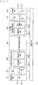
- Fig. 1 illustrates a high voltage direct current (HVDC) transmission system according to an embodiment.
- a HVDC system 100 includes a power generation part 101, a transmission side alternating current (AC) part 110, a transmission side power transformation part 103, a direct current (DC) power transmission part 140, a customer side power transformation part 105, a customer side AC part 170, a customer part 180, and a control unit 190.
- the transmission side power transformation part 103 includes a transmission side transformer part 120, and a transmission side AC-DC converter part 130.
- the customer side power transformation part 105 includes a customer side DC-AC converter part 150, and a customer side transformer part 160.
- the power generation part 101 generates three-phase AC power.
- the power generation part 101 may include a plurality of power generating plants.
- the transmission side AC part 110 transmits the three-phase AC power generated by the generation part 101 to a DC power transformation substation including the transmission side transformer part 120 and the transmission side AC-DC converter part 130.
- the transmission side transformer part 120 isolates the transmission side AC part 110 from the transmission side AC-DC converter part 130 and the DC power transmission part 140.
- the transmission side AC-DC converter part 130 converts the three-phase AC power corresponding to the output of the transmission side transformer part 120 into DC power.
- the DC power transmission part 140 transfers the transmission side DC power to the customer side.
- the customer side DC-AC converter part 150 converts the DC power transferred by the DC power transmission part 140 into three-phase AC power.
- the customer side transformer part 160 isolates the customer side AC part 170 from the customer side DC-AC converter part 150 and the DC power transmission part 140.
- the customer side AC part 170 provides three-phase AC power corresponding to the output of the customer side transformer part 160 to the customer part 180.
- the control unit 190 controls at least one of the power generation part 101, the transmission side AC part 110, the transmission side power transformation part 103, the DC power transmission part 140, the customer side power transformation part 105, the customer side AC part 170, the customer part 180, the control unit 190, the transmission side AC-DC converter part 130, and the customer side DC-AC converter part 150.
- the control unit 190 may control the turn-on and turn-off timings of a plurality of valves in the transmission side AC-DC converter part 130 and the customer side DC-AC converter part 150.
- the valves may correspond to a thyristor or an insulated gate bipolar transistor (IGBT).
- Fig. 2 illustrates a monopolar-type high voltage direct current (HVDC) transmission system.
- Fig. 2 illustrates a system which transmits DC power with a single pole.
- the single pole is described on the assumption that it is a positive pole, but is not necessarily limited thereto.
- the transmission side AC part 110 includes an AC power transmission line 111 and an AC filter 113.
- the AC power transmission line 111 transfers the three-phase AC power generated by the generation part 101 to the transmission side power transformation part 103.
- the AC filter 113 removes remaining frequency components other than the frequency component used by the power transformation part 103 from the transferred three-phase AC power.
- the transmission side transformer part 120 includes one or more transformers 121 for the positive pole.
- the transmission side AC-DC converter part 130 includes an AC-positive pole DC converter 131 which generates positive pole DC power, and the AC-positive pole DC converter 131 includes one or more three-phase valve bridges 131a respectively corresponding to the one or more transformers 121.
- the AC-positive pole DC converter 131 may generate positive pole DC power having six pulses by using the AC power.
- a primary coil and a secondary coil of one of the transformers 121 may have a Y-Y connection or a Y-delta ( ⁇ ) connection.
- the AC-positive pole DC converter 131 may generate positive pole DC power having 12 pulses by using the AC power.
- a primary coil and a secondary coil of one of the two transformers 121 may have a Y-Y connection
- a primary coil and a secondary coil of the other of the two transformers 121 may have a Y- ⁇ connection
- the AC-positive pole DC converter 131 may generate positive pole DC power having 18 pulses by using the AC power. The more the number of the pulses of the positive pole DC power becomes, the lower the price of the filter becomes.
- the DC power transmission part 140 includes a transmission side positive pole DC filter 141, a positive pole DC power transmission line 143, and a customer side positive pole DC filter 145.
- the transmission side positive pole DC filter 141 includes an inductor L1 and a capacitor C1 and performs DC filtering on the positive pole DC power output by the AC-positive pole DC converter 131.
- the positive pole DC power transmission line 143 has a single DC line for transmission of the positive pole DC power, and the earth may be used as a current feedback path.
- One or more switches may be disposed on the DC line.
- the customer side positive pole DC filter 145 includes an inductor L2 and a capacitor C2 and performs DC filtering on the positive pole DC power transferred through the positive pole DC power transmission line 143.
- the customer side DC-AC converter part 150 includes a positive pole DC-AC converter 151 and one or more three-phase valve bridges 151a.
- the customer side transformer part 160 includes, for the positive pole, one or more transformers 161 respectively corresponding to one or more three-phase valve bridges 151a.
- the positive pole DC-AC converter 151 may generate AC power having six pulses by using the positive pole DC power.
- a primary coil and a secondary coil of one of the transformers 161 may have a Y-Y connection or a Y-delta ( ⁇ ) connection.
- the positive pole DC-AC converter 151 may generate AC power having 12 pulses by using the positive pole DC power.
- a primary coil and a secondary coil of one of the two transformers 161 may have a Y-Y connection, and a primary coil and a secondary coil of the other of the two transformers 161 may also have a Y- ⁇ connection.
- the positive pole DC-AC converter 151 may generate AC power having 18 pulses by using the positive pole DC power. The more the number of the pulses of the AC power becomes, the lower the price of the filter becomes.
- the customer side AC part 170 includes an AC filter 171 and an AC power transmission line 173.
- the AC filter 171 removes frequency components other than the frequency component (for example, 60Hz) used by the customer part 180 from the AC power generated by the customer side power transformation part 105.
- the AC power transmission line 173 transfers the filtered AC power to the customer part 180.
- Fig. 3 illustrates a bipolar type HVDC transmission system according to an embodiment.
- Fig. 3 illustrates a system which transmits DC power with two poles.
- the two poles are described assuming a positive pole and a negative pole, but are not necessarily limited thereto.
- the transmission side AC part 110 includes an AC transmission line 111 and an AC filter 113.
- the AC power transmission line 111 transfers the three-phase AC power generated by the generation part 101, to the transmission side power transformation part 103.
- the AC filter 113 removes frequency components other than the frequency component used by the power transformation part 103 from the transferred three-phase AC power.
- the transmission side transformer part 120 includes one or more transformers 121 for the positive pole, and one or more transformers 122 for the negative pole.
- the transmission side AC-DC converter part 130 includes an AC-positive pole DC converter 131 which generates positive pole DC power and an AC-negative pole DC converter 132 which generates negative pole DC power.
- the AC-positive pole DC converter 131 includes one or more three-phase valve bridges 131a respectively corresponding to the one or more transformers 121 for the positive pole.
- the AC-negative pole DC converter 132 includes one or more three-phase valve bridges 132a respectively corresponding to the one or more transformers 122 for the negative pole.
- the AC-positive pole DC converter 131 may generate positive pole DC power having six pulses by using the AC power.
- a primary coil and a secondary coil of one of the transformers 121 may have a Y-Y connection or a Y-delta ( ⁇ ) connection.
- the AC-positive pole DC converter 131 may generate positive pole DC power having 12 pulses by using the AC power.
- a primary coil and a secondary coil of one of the two transformers 121 may have a Y-Y connection
- a primary coil and a secondary coil of the other of the two transformers 121 may have a Y- ⁇ connection.
- the AC-positive pole DC converter 131 may generate positive pole DC power having 18 pulses by using the AC power. The more the number of the pulses of the positive pole DC power becomes, the lower the price of the filter becomes.
- the AC-negative pole DC converter 132 may generate negative pole DC power having six pulses.
- a primary coil and a secondary coil of one of the transformers 122 may have a Y-Y connection or a Y-delta ( ⁇ ) connection.
- the AC-negative pole DC converter 132 may generate negative pole DC power having 12 pulses.
- a primary coil and a secondary coil of one of the two transformers 122 may have a Y-Y connection
- a primary coil and a secondary coil of the other of the two transformers 122 may have a Y- ⁇ connection.
- the AC-negative pole DC converter 132 may generate negative pole DC power having 18 pulses. The more the number of the pulses of the negative pole DC power becomes, the lower the price of the filter becomes.
- the DC power transmission part 140 includes a transmission side positive pole DC filter 141, a transmission side negative pole DC filter 142, a positive pole DC power transmission line 143, a negative pole DC power transmission line 144, a customer side positive pole DC filter 145, and a customer side negative pole DC filter 146.
- the transmission side positive pole DC filter 141 includes an inductor L1 and a capacitor C1 and performs DC filtering on the positive pole DC power output by the AC-positive pole DC converter 131.
- the transmission side negative pole DC filter 142 includes an inductor L3 and a capacitor C3 and performs DC filtering on the negative pole DC power output by the AC-negative pole DC converter 132.
- the positive pole DC power transmission line 143 has a single DC line for transmission of the positive pole DC power, and the earth may be used as a current feedback path.
- One or more switches may be disposed on the DC line.
- the negative pole DC power transmission line 144 has a single DC line for transmission of the negative pole DC power, and the earth may be used as a current feedback path.
- One or more switches may be disposed on the DC line.
- the customer side positive pole DC filter 145 includes an inductor L2 and a capacitor C2 and performs DC filtering on the positive pole DC power transferred through the positive pole DC power transmission line 143.
- the customer side negative pole DC filter 146 includes an inductor L4 and a capacitor C4 and performs DC filtering on the negative pole DC power transferred through the negative pole DC power transmission line 144.
- the customer side DC-AC converter part 150 includes a positive pole DC-AC converter 151 and a negative pole DC-AC converter 152.
- the positive pole DC-AC converter 151 includes one or more three-phase valve bridges 151a and the negative pole DC-AC converter 152 includes one or more three-phase valve bridges 152a.
- the customer side transformer part 160 includes, for the positive pole, one or more transformers 161 respectively corresponding to one or more three-phase valve bridges 151a, and for the negative pole, one or more transformers 162 respectively corresponding to one or more three-phase valve bridges 152a.
- the positive pole DC-AC converter 151 may generate AC power having six pulses by using the positive pole DC power.
- a primary coil and a secondary coil of one of the transformers 161 may have a Y-Y connection or a Y-delta ( ⁇ ) connection.
- the positive pole DC-AC converter 151 may generate AC power having 12 pulses by using the positive pole DC power.
- a primary coil and a secondary coil of one of the two transformers 161 may have a Y-Y connection
- a primary coil and a secondary coil of the other of the two transformers 161 may have a Y- ⁇ connection.
- the positive pole DC-AC converter 151 may generate AC power having 18 pulses by using the positive pole DC power. The more the number of the pulses of the AC power becomes, the lower the price of the filter becomes.
- the negative pole DC-AC converter 152 may generate AC power having six pulses by using the negative pole DC power.
- a primary coil and a secondary coil of one of the transformers 162 may have a Y-Y connection or a Y-delta ( ⁇ ) connection.
- the negative pole DC-AC converter 152 may generate AC power having 12 pulses by using the negative pole DC power.
- a primary coil and a secondary coil of one of the two transformers 162 may have a Y-Y connection
- a primary coil and a secondary coil of the other of the two transformers 162 may have a Y- ⁇ connection.
- the negative pole DC-AC converter 152 may generate AC power having 18 pulses by using the negative pole DC power. The more the number of the pulses of the AC power become, the lower the price of the filter becomes.
- the customer side AC part 170 includes an AC filter 171 and an AC power transmission line 173.
- the AC filter 171 removes frequency components other than the frequency component (for example, 60Hz) used by the customer part 180 from the AC power generated by the customer side power transformation part 105.
- the AC power transmission line 173 transfers the filtered AC power to the customer part 180.
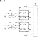
- Fig. 4 illustrates a connection between a transformer and a three-phase valve bridge according to an embodiment.
- Fig. 4 illustrates the connection between the two transformers 121 for the positive pole and the two three-phase valve bridges 131a for the positive pole. Since the connection between the two transformers 122 for the negative pole and the two three-phase valve bridges 132a for the negative pole, the connection between the two transformers 161 for the positive pole and the two three-phase valve bridges 151a for the positive pole, the connection between the two transformers 162 for the negative pole and the two three-phase valve bridges 152a for the negative pole, the connection between the one transformer 121 for the positive pole and the one three-phase valve bridge 131a for the positive pole, the connection between the one transformer 161 for the positive pole and the one three-phase valve bridge 151a for the positive pole, etc., could be easily derived from the embodiment of Fig. 4 , drawings and descriptions thereof will not be provided herein.
- the transformer 121 having the Y-Y connection is referred to as an upper transformer
- the transformer 121 having the Y- ⁇ connection is referred to as a lower transformer
- the three-phase valve bridge 131a connected to the upper transformer is referred to as upper three-phase valve bridge
- the three-phase valve bridge 131a connected to the lower transformer is referred to as lower three-phase valve bridge.
- the upper three-phase valve bridge and the lower three-phase valve bridge have two output terminals outputting DC power, i.e., a first output terminal OUT1 and a second output terminal OUT2.
- the upper three-phase valve bridge includes six valves D1 to D6, and the lower three-phase valve bridges include six valves D7 to D12.
- the valve D1 has a cathode connected to the first output terminal OUT1 and an anode connected to a first terminal of the secondary coil of the upper transformer.
- the valve D2 has a cathode connected to the anode of the valve D5 and an anode connected to the anode of the valve D6.
- the valve D3 has a cathode connected to the first output terminal OUT1 and an anode connected to a second terminal of the secondary coil of the upper transformer.
- the valve D4 has a cathode connected to the anode of the valve D1 and an anode connected to the anode of the valve D6.
- the valve D5 has a cathode connected to the first output terminal OUT1 and an anode connected to a third terminal of the secondary coil of the upper transformer.
- the valve D6 has a cathode connected to the anode of the valve D3.
- the valve D7 has a cathode connected to the anode of the valve D6 and an anode connected to a first terminal of the secondary coil of the lower transformer.
- the valve D8 has a cathode connected to the anode of the valve D11 and an anode connected to a second output terminal OUT2.
- the valve D9 has a cathode connected to the anode of the valve D6 and an anode connected to a second terminal of the secondary coil of the lower transformer.
- the valve D10 has a cathode connected to the anode of the valve D7 and an anode connected to the second output terminal OUT2.
- the valve D11 has a cathode connected to the anode of the valve D6 and an anode connected to a third terminal of the secondary coil of the lower transformer.
- the valve D12 has a cathode connected to the anode of the valve D9 and an anode connected to the second output terminal OUT2.
- the customer side DC-AC converter part 150 may be configured as a modular multi-level converter 200.
- the modular multi-level converter 200 may convert DC power into AC power by using a plurality of sub-modules 210.
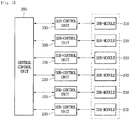
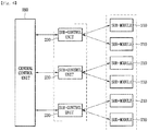
- Figs. 5 and 6 are block diagrams illustrating a modular multi-level converter 200.
- the modular multi-level converter 200 includes a central control unit 250, a plurality of sub-control units 230 and a plurality of sub-modules 210.
- the central control unit 250 controls the plurality of sub-control units 230, and the sub-control units 230 may respectively control the sub-modules 210 connected thereto.
- one sub-control unit 230 is connected to one sub-module 210, and accordingly, may control the switching operation of the one sub-module 210 connected thereto based on a control signal transferred through the central control unit 250.
- one sub-control unit 230 is connected to a plurality of sub-modules 210, and accordingly, may confirm each of the control signals for the plurality of sub-modules 210 connected thereto based on a plurality of control signals transferred through the central control unit 250; each of the plurality of sub-modules 210 may be controlled based on the confirmed control signal.
- the central control unit 250 determines the operation condition of the plurality of sub-modules 210, and generates a control signal to control the operation of the plurality of sub-modules 210 according to the determined operation condition.
- the operation condition may include a discharging operation, a charging operation, and a bypassing operation.
- the addresses which sequentially increase from the front according to the arranged sequence of the sub-modules, are assigned to the plurality of sub-modules 210, respectively.
- the sub-module 210 may perform any one of the discharging operation, the charging operation, and the bypassing operation after receiving DC power.
- the sub-module 210 includes a switching element having a diode, and accordingly, may perform any one of the discharging operation, the charging operation, and the bypassing operation of the sub-module 210 by a switching operation and the rectifying operation of the diode.
- Each of the sub-control unit 230 receives a switching signal for controlling the plurality of sub-modules 210 through the central control unit 250, and controls the switching operation of the sub-module 210 according to the received switching signal.
- the central control unit 250 may control the overall operations of the modular multi-level converter 200.
- the central control unit 250 may measure the current and voltage of the AC parts 110 and 170 and Dc power transmission part 140, which are interconnected thereto.
- the central control unit 250 may calculate an overall control value.
- the overall control value may be a target value for the voltage, current, frequency of the output AC power of the modular multi-level converter 200.
- the central control unit 250 may calculate an overall control value based on one or more of the current and the voltage of the AC parts 110 and 170 which are interconnected with the modular multi-level converter 200 and the current and the voltage of the DC power transmission part 140.
- the central control unit 250 may also control the operation of the modular multi-level converter 200 based on one or more from the reference active power, the reference reactive power, the reference current, the reference voltage received from an upper layer control unit (not shown) through a communications apparatus (not shown).
- the central control unit 250 may transmit and receive data to/from the sub-control unit 230.
- the central control unit 250 described herein assigns addresses according to the arranged sequence of the plurality of sub-modules 210, and determines the switching sequence of the plurality of sub-modules 210 by using the assigned addresses.
- all the sub-modules 210 do not operate under the same switching conditions, but a certain sub-module performs a charging operation or a bypassing operation according to the present required voltage, and the remaining sub-modules perform a discharging operation.
- the central control unit 250 should firstly determine the sub-module which will perform the discharging operation.
- the service life of the plurality of sub-modules 210 may be increased only if the plurality of sub-modules 210 perform the discharging operations within balanced frequencies with each other.
- the switching sequence of the plurality of sub-modules 210 is determined according to the sequence of the addresses which are sequentially assigned.
- the central control unit 250 allows the discharging operations to be performed from the address 1.
- the number of the sub-modules, in which the discharging operations are performed is determined on the basis of a charged voltage value and a target value of each of the plurality of sub-modules.
- the central control unit 250 determines the switching conditions such that the sum of the charged voltage values of the plurality of sub-modules reach the target value. In other words, if power corresponding to the target value may be output by discharging even when the sub-modules assigned with address 1 and 2 are discharged, the central control unit 250 allows only the sub-modules assigned with addresses 1 and 2 to perform the discharging operations.
- the central control unit 250 determines that a discharge operation is performed starting from a sub-module next to the sub-module having the latest address among the sub-modules previously performing discharging operations.
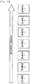
- Fig. 7 illustrates connections of the plurality of sub-modules 210 included in the modular multi-level converter 200.
- the plurality of sub-modules 210 may be serially connected, and the plurality of sub-modules 210 connected to a positive pole or negative pole of one phase may constitute one arm.
- the three-phase modular multi-level converter 200 may normally include six arms, and include a positive pole and a negative pole for each of the three-phases A, B, and C to form the six arms.
- the three-phase modular multi-level converter 200 may include: a first arm 221 including a plurality of sub-modules for a positive pole of phase A; a second arm 222 including a plurality of sub-modules for a negative pole of phase A; a third arm 223 including a plurality of sub-modules for a positive pole of phase B; a fourth arm 224 including a plurality of sub-modules for a negative pole of phase B; a fifth arm 225 including a plurality of sub-modules for a positive pole of phase C; and a sixth arm 226 including a plurality of sub-modules for a negative pole of phase C.
- the plurality of sub-modules 210 for one phase may constitute a leg.
- the three-phase modular multi-level converter 200 may include a phase A leg 227 including a plurality of sub-modules 210 for phase A; a phase B leg 228 including a plurality of sub-modules 210 for phase B; and a phase C leg 229 including a plurality of sub-modules 210 for phase C.
- the first to six arms 221 to 226 are respectively included in the phase A leg 227, the phase B leg 228, and phase C leg 229.
- phase A leg 227 the first arm 221, which is the positive pole arm of phase A, and the second arm 222, which is the negative pole arm of phase A, are included; and in the phase B leg 228, the third arm 223, which is the positive pole arm of phase B, and the fourth arm 224, which is the negative pole arm of phase B, are included. Also, in the phase C leg 229, the fifth arm 225, which is the positive pole arm of phase C, and the sixth arm 226, which is the negative pole arm of phase C, are included
- the plurality of sub-modules 210 may constitute a positive pole arm 227 and a negative pole arm 228 according to polarity.
- the plurality of sub-modules 210 included in the modular multi-level converter 200 may be classified, with respect to a neutral line n, into a plurality of sub-modules 210 corresponding to the positive pole and a plurality of sub-modules 210 corresponding to the negative pole.
- the modular multi-level converter 200 may include a positive arm 227 including the plurality of sub-modules 210 corresponding to the positive pole, and a negative arm 228 including the plurality of sub-modules 210 corresponding to the negative pole.
- the positive pole arm 227 may include the first arm 221, the third arm 223, and the fifth arm 225; and the negative pole arm 228 may include the second arm 222, the fourth arm 224, and the sixth arm 226.
- Fig. 8 is an exemplary view illustrating a configuration of the sub-module 210.
- the sub-module 210 includes two switches, two diodes, and a capacitor. Such a shape of the sub-module 210 is also referred to as a half-bridge shape or a half bridge inverter.
- the switch included in a switching part 217 may include a power semiconductor.
- the power semiconductor refers to a semiconductor element for a power apparatus, and may be optimized for the conversion or control of electric power. Also, the power semiconductor is referred to as a valve unit.
- the switch included in the switching part 217 may include a power semiconductor, for example, may include an insulated gate bipolar transistor (IGBT), a gate turn-off thyristor, an integrated gate commutated thyristor, etc.
- a power semiconductor for example, may include an insulated gate bipolar transistor (IGBT), a gate turn-off thyristor, an integrated gate commutated thyristor, etc.
- the storage part 219 includes the capacitor, and thus may charge or discharge energy.
- the sub-module 210 may be represented as an equivalent model based on the configuration and the operation of the sub-module 210.
- Fig. 9 illustrates an equivalent model of the sub-module 210, and referring to Fig. 9 , the sub-module 210 may be illustrated as an energy charge and discharge unit including a switch and a capacitor.
- the sub-module 210 is the same as an energy charge and discharge unit having an output voltage of Vsm.
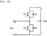
- the switch part 217 of the sub-module 210 of Figs. 10 to 13 includes a plurality of switches T1 and T2, and each of the switches is connected to each of diodes D1 and D2. Also, the storage part 219 of the sub-module 210 includes a capacitor.
- Figs. 10 and 11 illustrate formation of the capacitor voltage Vsm of the sub-module 210.
- Figs. 10 and 11 illustrate a state in which the switch T1 of the switching part 217 is turned on and the switch T2 is turned off. Accordingly, the sub-module 210 may form the capacitor voltage according to each of the switching operations.
- the current introduced into the sub-module 210 is transferred to the capacitor via the diode D1 and thus forms the capacitor voltage. Then, the formed capacitor voltage may charge energy into the capacitor.
- the sub-module 210 may perform discharging operation of discharging the charged energy.
- the stored energy of the capacitor which is energy charged into the sub-module 210, is discharged via the switch T1. Accordingly, the sub-module 210 may discharge the stored energy.
- Figs. 12 and 13 illustrate the formation of a zero voltage of the sub-module 210.
- Figs. 12 and 13 illustrate a state in which the switch T1 of the switching part 217 is turned off and the switch T2 is turned-on. Accordingly, current does not flow to the capacitor of the sub-module 210, and the sub-module 210 may form a zero voltage.
- the current introduced into the sub-module 210 is output through the switch T2 and the sub-module may form a zero voltage.
- the current introduced into the sub-module 210 is output through the diode D2 and the sub-module 210 may form a zero voltage.
- the sub-module 210 may form the zero voltage, and thus perform the bypassing operation in which the current does not flow into the sub-module 210 but bypasses the sub-module 210.
- Figs. 14 to 16 are views illustrating an operation of determining a switching sequence of a modular multi-level converter according to an embodiment.
- the central control unit 250 sequentially assigns addresses from the sub-module 1.
- address 1 may be assigned to the sub-module 1
- address 2 may be assigned to the sub-module 2
- address 3 may be assigned to the sub-module 3
- address 4 may be assigned to the sub-module 4
- address 5 may be assigned to the sub-module 5
- address 6 may be assigned to the sub-module 6
- address 7 may be assigned to the sub-module 7.
- the central control unit 250 sequentially determines the switching sequence from the address 1.
- the switching sequence is determined based on the charged voltage, which each of the sub-modules has, and a target voltage.
- the central control unit 250 determines the switching sequence of the sub-modules to meet the target voltage.
- the central control unit 250 allows, according to the address sequence, only the sub-module 1, the sub-module 2, and the sub-module 3 to perform the discharging operations, and allows the remaining sub-modules to perform the bypassing operation or charging operation.
- the central control unit 250 remembers the sub-module which has the latest address among the sub-modules performing the discharging operations.
- the switching sequence is determined from the address next to the address of the remembered sub-module.
- the central control unit 250 allows only the sub-module 4, and the sub-module 5 to perform the discharging operations, and allows the remaining sub-modules to perform the bypassing operation or charging operation. Also, as described above, the central control unit 250 remembers information regarding the sub-module 5 which is assigned with the latest address among the sub-modules performing the discharging operations, and applies the remembered information when determining the switching condition later.
- the switching sequence of the plurality of sub-modules is determined according to the assigned addresses, so that the time required to determine the operation condition of the sub-modules may be reduced.
- a plurality of sub-modules are switched according to the address sequence to maintain a balance of the switching frequencies of the plurality of sub-modules, so that a situation in which only a certain sub-module is continuously switched may be prevented in advance, and a situation in which the service life of the certain sub-module is reduced may also be prevented.
- Figs. 17 and 18 are flowcharts illustrating, step by step, a method of determining a switching sequence of a modular multi-level converter according to an embodiment.
- the central control unit 250 assigns addresses according to the arranged sequence of the sub-modules (operation S100). That is, the lowest address is assigned to the frontmost one of the sub-modules, and the highest address is assigned to the sub-module which is disposed at the last.
- the central control unit 250 confirms a target voltage and the charged voltages of the plurality of sub-modules (operation S110).
- the central control unit 250 sequentially determines a switching sequence from the sub-module having the lowest address based on the target voltage and the charged voltages (operation S120).
- the central control unit 250 remembers the information on the sub-module which is assigned with the last address among the sub-modules performing the discharging operations, and later, determines the switching conditions of the sub-modules using the remembered information.
- the central control unit 250 confirms the target voltage and the charged voltages of the sub-modules (operation S200).
- the central control unit 250 confirms the sub-module which has the last address among the sub-modules which performed discharging operations at the previous time (operation S210).
- the central control unit 250 determines a switching sequence to output the target voltage from the sub-module having the address next to the confirmed sub-module (operation S220).
- the output voltage corresponding to the target voltage is generated (operation S230) .
- the switching sequence of the plurality of sub-modules is determined according to the assigned addresses, so that the time required to determine the operation condition of the sub-modules may be reduced.
- a plurality of sub-modules are switched according to the address sequence to maintain a balance of the switching frequencies of the plurality of sub-modules, so that a situation in which only a certain sub-module is continuously switched may be prevented in advance, and a situation in which the service life of the certain sub-module is reduced may also be prevented.
Landscapes
- Engineering & Computer Science (AREA)
- Power Engineering (AREA)
- Inverter Devices (AREA)
- Charge And Discharge Circuits For Batteries Or The Like (AREA)
- Supply And Distribution Of Alternating Current (AREA)
- Rectifiers (AREA)
Claims (2)
- Modularer Mehrstufenwandler, umfassend:eine Vielzahl von Untermodulen (210), die Schaltelemente umfassen; undeine zentrale Steuereinheit (250), die so konfiguriert ist, dass sie jedem der Vielzahl von Untermodulen (210) von der Vorderseite gemäß einer Platzierungssequenz der Vielzahl von Untermodulen (210) sequenziell eine Adresse zuweist, um jedes der Vielzahl von Untermodulen zu unterscheiden, Schaltvorgangsbedingungen der Vielzahl von Untermodulen (210) auf Basis der zugewiesenen Adressen ermittelt und Schaltsignale entsprechend den ermittelten Schaltvorgangsbedingungen ausgibt,wobei die Schaltvorgangsbedingungen eine Ladevorgangsbedingung, eine Entladevorgangsbedingung und eine Umgehungsvorgangsbedingung beinhalten,dadurch gekennzeichnet, dassdie zentrale Steuereinheit (250) so konfiguriert ist, dass sie das Durchführen von Entladevorgängen sequenziell von dem Untermodul, das die niedrigste Adresse aufweist, auf Basis einer Zielspannung und geladenen Spannungen der Vielzahl von Untermodule erlaubt,wobei die niedrigste Adresse dem vordersten der Untermodule zugewiesen wird und eine höchste Adresse dem Untermodul zugewiesen wird, das als Letztes angeordnet ist,wobei, wenn die Untermodule, die unter der Entladevorgangsbedingung betrieben werden, ermittelt sind, die zentrale Steuereinheit (250) Informationen auf einem Untermodul speichert, dass die letzte Adresse unter den Untermodulen hat, die unter der Entladevorgangsbedingung betrieben werden,wobei die zentrale Steuereinheit (250) ein Untermodul bestätigt, das die letzte Adresse hat und einen Entladevorgang zu einem früheren Zeitpunkt durchgeführt hat, und das sequenzielle Durchführen eines Entladevorgangs beginnend mit einem Untermodul erlaubt, das die nächste Adresse nach der Adresse des bestätigten Untermoduls hat,wobei die Vielzahl von Untermodulen (210) eine Halbbrückenform haben.
- Modularer Mehrstufenwandler nach Anspruch 1,
wobei eine Summe der Spannungen, die in Untermodulen geladen sind, die die Entladevorgänge durchführen, der Zielspannung entspricht, und
wobei die zentrale Steuereinheit (250) die geladenen Spannungen von dem Untermodul bestätigt, das die niedrigste Adresse hat, und eine Schaltvorgangsbedingung von jedem der Untermodule ermittelt, um eine Ausgangsspannung zu erzeugen, die der Zielspannung entspricht.
Applications Claiming Priority (1)
| Application Number | Priority Date | Filing Date | Title |
|---|---|---|---|
| KR1020140057356A KR101666712B1 (ko) | 2014-05-13 | 2014-05-13 | 모듈형 멀티레벨 컨버터 |
Publications (2)
| Publication Number | Publication Date |
|---|---|
| EP2945273A1 EP2945273A1 (de) | 2015-11-18 |
| EP2945273B1 true EP2945273B1 (de) | 2018-12-26 |
Family
ID=53054870
Family Applications (1)
| Application Number | Title | Priority Date | Filing Date |
|---|---|---|---|
| EP15165599.0A Active EP2945273B1 (de) | 2014-05-13 | 2015-04-29 | Modularer mehrstufenumrichter |
Country Status (6)
| Country | Link |
|---|---|
| US (1) | US9680392B2 (de) |
| EP (1) | EP2945273B1 (de) |
| JP (1) | JP6023263B2 (de) |
| KR (1) | KR101666712B1 (de) |
| CN (1) | CN105099219B (de) |
| ES (1) | ES2711884T3 (de) |
Families Citing this family (29)
| Publication number | Priority date | Publication date | Assignee | Title |
|---|---|---|---|---|
| JP3164626B2 (ja) | 1992-01-27 | 2001-05-08 | 松下電器産業株式会社 | 二段圧縮式冷凍サイクル装置 |
| EP3005543B1 (de) * | 2013-07-15 | 2020-03-25 | Siemens Aktiengesellschaft | Modularer multilevel dc/dc wandler für hvdc anwendungen |
| EP2897268B1 (de) * | 2014-01-20 | 2022-01-05 | ABB Schweiz AG | Master/slave regelungssystem in ringtopologie für modulare mehrpunktumrichter |
| WO2015113642A1 (en) * | 2014-02-03 | 2015-08-06 | Abb Technology Ltd | A multi-level power converter and a method for controlling a multi-level power converter |
| US10732685B2 (en) * | 2015-02-27 | 2020-08-04 | Ge Energy Power Conversion Technology Limited | System and method for operating power converters |
| US9520801B1 (en) * | 2015-08-12 | 2016-12-13 | General Electric Company | Method and system for a gas tube switch-based voltage source high voltage direct current transmission system |
| US9748857B2 (en) * | 2015-08-12 | 2017-08-29 | General Electric Company | Method and system for a gas tube-based current source high voltage direct current transmission system |
| WO2017171182A1 (ko) * | 2016-03-30 | 2017-10-05 | 두산중공업 주식회사 | 풍력 발전 시스템의 컨버터 구동 장치 및 컨버터 제어 장치, 풍력 발전 시스템의 스위칭 소자 모듈 구동 장치 및 스위칭 소자 모듈 제어 장치 |
| KR101838181B1 (ko) * | 2016-04-14 | 2018-03-13 | 두산중공업 주식회사 | 풍력 발전 시스템의 스위칭 소자 모듈 구동 장치 및 방법 |
| KR101668431B1 (ko) * | 2016-05-02 | 2016-10-24 | 주식회사 효원파워텍 | 모듈형 멀티레벨 컨버터의 서브모듈 전압 추정 방법 및 장치 |
| KR101840117B1 (ko) | 2016-07-06 | 2018-03-19 | 명지대학교 산학협력단 | 송전 시스템에서 컨버터 선충전 방법 및 이를 위한 제어기 |
| KR102600766B1 (ko) * | 2016-09-22 | 2023-11-13 | 엘에스일렉트릭(주) | 모듈형 멀티레벨 컨버터 |
| KR101923690B1 (ko) * | 2016-11-11 | 2018-11-29 | 엘에스산전 주식회사 | 전력보상장치의 서브모듈성능시험을 위한 합성시험회로 및 그 시험방법 |
| CN108566101B (zh) | 2016-12-16 | 2020-09-22 | 台达电子企业管理(上海)有限公司 | 模块化电源系统 |
| KR102393893B1 (ko) * | 2017-04-17 | 2022-05-03 | 엘에스일렉트릭(주) | 전력보상장치의 서브모듈의 성능시험을 위한 시험 회로 |
| US11289996B2 (en) * | 2017-07-31 | 2022-03-29 | Siemens Energy Global GmbH & Co. KG | Converter assembly with an ability to disconnect a fault current and a method for disconnecting a fault current at a converter assembly of this type |
| CN108111030B (zh) * | 2017-12-07 | 2020-09-15 | 上海交通大学 | 混合型海上风场直流换流器 |
| KR102490765B1 (ko) * | 2018-05-28 | 2023-01-20 | 엔알 일렉트릭 컴퍼니 리미티드 | 보상기 및 그의 제어 방법 및 장치 |
| CN110971132B (zh) * | 2018-09-30 | 2023-10-20 | 西门子股份公司 | 模块化多电平换流器的控制系统、方法、装置和子模块 |
| EP3654517B1 (de) * | 2018-11-19 | 2021-06-02 | Maschinenfabrik Reinhausen GmbH | Betrieb eines modularen multilevel umrichters |
| PE20212032A1 (es) | 2019-03-29 | 2021-10-20 | Tae Tech Inc | Sistemas de energia basados en modulos que pueden presentar configuraciones en cascada e interconectadas y metodos relacionados con los mismos |
| EP3726718A1 (de) * | 2019-04-19 | 2020-10-21 | General Electric Technology GmbH | Verbesserungen an oder im zusammenhang mit hgü-umrichterstationen |
| CN110556852B (zh) * | 2019-09-29 | 2021-01-08 | 东北大学 | 基于soc动态均衡子模块检索的分布式储能系统及控制方法 |
| CN110943471A (zh) * | 2019-11-07 | 2020-03-31 | 长沙理工大学 | 基于系统能量最优分布的mmc故障控制策略 |
| CN111953002A (zh) * | 2020-08-17 | 2020-11-17 | 广东电网有限责任公司 | 一种换流阀快速耗能装置及方法 |
| CN113110119B (zh) * | 2020-11-26 | 2022-08-19 | 国网天津市电力公司 | 一种电子式全自动支路交换器 |
| KR102470345B1 (ko) * | 2020-12-08 | 2022-11-25 | 효성중공업 주식회사 | 모듈형 멀티 레벨 컨버터의 초기 충전 장치 및 방법 |
| US20240421722A1 (en) * | 2021-09-13 | 2024-12-19 | Hitachi Energy Ltd | Charging of a modular multilevel converter |
| DE102023128073B3 (de) | 2023-10-13 | 2025-01-16 | p&e power&energy GmbH | Verfahren, Computerprogramm und Vorrichtung zum Steuern mehrerer Einheiten mittels einer übergeordneten Steuerung |
Family Cites Families (19)
| Publication number | Priority date | Publication date | Assignee | Title |
|---|---|---|---|---|
| US3867643A (en) | 1974-01-14 | 1975-02-18 | Massachusetts Inst Technology | Electric power converter |
| US4062057A (en) * | 1977-04-15 | 1977-12-06 | The United States Of America As Represented By The Secretary Of The Navy | Regulated power supply having a series arrangement of inverters |
| JPH10276093A (ja) * | 1997-03-28 | 1998-10-13 | Sony Corp | D/a変換器 |
| US7024257B2 (en) | 2001-02-09 | 2006-04-04 | Motion Engineering, Inc. | System for motion control, method of using the system for motion control, and computer-readable instructions for use with the system for motion control |
| WO2006118026A1 (ja) * | 2005-04-27 | 2006-11-09 | Kabushiki Kaisha Yaskawa Denki | 電力変換装置と電力変換方法 |
| JP2006320103A (ja) | 2005-05-12 | 2006-11-24 | Fuji Electric Systems Co Ltd | 直列多重電力変換装置の制御装置 |
| US8631483B2 (en) * | 2005-06-14 | 2014-01-14 | Texas Instruments Incorporated | Packet processors and packet filter processes, circuits, devices, and systems |
| US9088178B2 (en) * | 2006-12-06 | 2015-07-21 | Solaredge Technologies Ltd | Distributed power harvesting systems using DC power sources |
| JP4825660B2 (ja) | 2006-12-26 | 2011-11-30 | 三菱電機株式会社 | 超電導コイル用電力変換装置 |
| WO2009030275A1 (en) * | 2007-09-05 | 2009-03-12 | Abb Technology Ag | Voltage source converter for high voltage direct current power transmission |
| WO2009086927A1 (en) * | 2008-01-08 | 2009-07-16 | Abb Technology Ag | A method for controlling a voltage source converter and a voltage converting apparatus |
| JP5449893B2 (ja) * | 2009-07-21 | 2014-03-19 | 株式会社日立製作所 | 電力変換装置 |
| EP2486645B1 (de) | 2009-10-06 | 2018-01-10 | ABB Research Ltd. | Veränderter aufbau eines spannungsgeführten umrichters |
| KR101088698B1 (ko) * | 2010-06-24 | 2011-12-01 | 동영전기 주식회사 | 병렬제어형 전원장치 |
| JP5592236B2 (ja) | 2010-11-01 | 2014-09-17 | 株式会社日立製作所 | 電力変換装置 |
| JP5734672B2 (ja) | 2011-01-12 | 2015-06-17 | 株式会社東芝 | 半導体電力変換装置 |
| JP5858217B2 (ja) | 2011-08-23 | 2016-02-10 | 富士電機株式会社 | 交流−交流変換回路 |
| US8982593B2 (en) | 2012-04-27 | 2015-03-17 | Rockwell Automation Technologies, Inc. | Cascaded H-Bridge (CHB) inverter level shift PWM with rotation |
| JP6012387B2 (ja) | 2012-10-12 | 2016-10-25 | 株式会社日立製作所 | 電力変換装置及び電力変換方法 |
-
2014
- 2014-05-13 KR KR1020140057356A patent/KR101666712B1/ko active Active
-
2015
- 2015-04-24 US US14/696,137 patent/US9680392B2/en active Active
- 2015-04-29 EP EP15165599.0A patent/EP2945273B1/de active Active
- 2015-04-29 ES ES15165599T patent/ES2711884T3/es active Active
- 2015-05-13 CN CN201510242693.XA patent/CN105099219B/zh active Active
- 2015-05-13 JP JP2015097945A patent/JP6023263B2/ja active Active
Non-Patent Citations (1)
| Title |
|---|
| None * |
Also Published As
| Publication number | Publication date |
|---|---|
| US9680392B2 (en) | 2017-06-13 |
| KR101666712B1 (ko) | 2016-10-14 |
| ES2711884T3 (es) | 2019-05-08 |
| KR20150130146A (ko) | 2015-11-23 |
| JP2015220991A (ja) | 2015-12-07 |
| CN105099219A (zh) | 2015-11-25 |
| US20150333654A1 (en) | 2015-11-19 |
| CN105099219B (zh) | 2017-10-27 |
| EP2945273A1 (de) | 2015-11-18 |
| JP6023263B2 (ja) | 2016-11-09 |
Similar Documents
| Publication | Publication Date | Title |
|---|---|---|
| EP2945273B1 (de) | Modularer mehrstufenumrichter | |
| US9083230B2 (en) | Multilevel voltage source converters and systems | |
| EP2945274B1 (de) | Modularer mehrstufenumrichter | |
| CN102714471B (zh) | 用于对储能器充电和放电的变流器和变流器的子模块 | |
| JP2010519890A (ja) | 三相で高電力の無停電電源 | |
| EP2887529A1 (de) | Phasenmodul eines modularen Mehrpunktumrichters mit Flat-Top PWM, Umrichter und hybride Umrichtertopologien | |
| EP3915826A1 (de) | Verfahren und system zum fahrzeug-zu-fahrzeug-laden von elektrofahrzeugen | |
| US10270250B2 (en) | Insulation design apparatus of high voltage direct current transmission system | |
| KR20170110322A (ko) | 변압기를 갖는 초고압 직류송전 시스템 | |
| KR101659252B1 (ko) | 모듈형 멀티레벨 컨버터 및 그의 제어 방법 | |
| CN110299860B (zh) | 用于中压逆变器的初始充电系统和用于控制该系统的方法 | |
| KR101678802B1 (ko) | 모듈형 멀티레벨 컨버터 및 그의 제어 방법 | |
| KR20150130863A (ko) | 모듈형 멀티레벨 컨버터 및 그의 제어 방법 | |
| KR20150130864A (ko) | 모듈형 멀티레벨 컨버터 및 그의 제어 방법 | |
| KR20160072499A (ko) | 모듈형 멀티 레벨 컨버터의 운전 방법 | |
| KR101622458B1 (ko) | Hvdc 시스템의 컨버터 장치 및 그의 제어 방법 | |
| CN106716816B (zh) | 转换器系统的拆分dc链路的充电 | |
| US20260100638A1 (en) | Active filter pre-charging for a converter with active filter cells | |
| KR101707735B1 (ko) | Hvdc 시스템의 컨버터 장치 및 그의 제어 방법 | |
| JPWO2015114823A1 (ja) | 電力変換装置および電力変換装置の制御方法 | |
| HK1174744B (en) | Converter and submodule of a converter for charging or discharging an energy store |
Legal Events
| Date | Code | Title | Description |
|---|---|---|---|
| PUAI | Public reference made under article 153(3) epc to a published international application that has entered the european phase |
Free format text: ORIGINAL CODE: 0009012 |
|
| AK | Designated contracting states |
Kind code of ref document: A1 Designated state(s): AL AT BE BG CH CY CZ DE DK EE ES FI FR GB GR HR HU IE IS IT LI LT LU LV MC MK MT NL NO PL PT RO RS SE SI SK SM TR |
|
| AX | Request for extension of the european patent |
Extension state: BA ME |
|
| 17P | Request for examination filed |
Effective date: 20160512 |
|
| RBV | Designated contracting states (corrected) |
Designated state(s): AL AT BE BG CH CY CZ DE DK EE ES FI FR GB GR HR HU IE IS IT LI LT LU LV MC MK MT NL NO PL PT RO RS SE SI SK SM TR |
|
| STAA | Information on the status of an ep patent application or granted ep patent |
Free format text: STATUS: EXAMINATION IS IN PROGRESS |
|
| 17Q | First examination report despatched |
Effective date: 20180216 |
|
| GRAP | Despatch of communication of intention to grant a patent |
Free format text: ORIGINAL CODE: EPIDOSNIGR1 |
|
| STAA | Information on the status of an ep patent application or granted ep patent |
Free format text: STATUS: GRANT OF PATENT IS INTENDED |
|
| INTG | Intention to grant announced |
Effective date: 20180716 |
|
| GRAS | Grant fee paid |
Free format text: ORIGINAL CODE: EPIDOSNIGR3 |
|
| GRAA | (expected) grant |
Free format text: ORIGINAL CODE: 0009210 |
|
| STAA | Information on the status of an ep patent application or granted ep patent |
Free format text: STATUS: THE PATENT HAS BEEN GRANTED |
|
| AK | Designated contracting states |
Kind code of ref document: B1 Designated state(s): AL AT BE BG CH CY CZ DE DK EE ES FI FR GB GR HR HU IE IS IT LI LT LU LV MC MK MT NL NO PL PT RO RS SE SI SK SM TR |
|
| REG | Reference to a national code |
Ref country code: GB Ref legal event code: FG4D |
|
| REG | Reference to a national code |
Ref country code: CH Ref legal event code: EP |
|
| REG | Reference to a national code |
Ref country code: AT Ref legal event code: REF Ref document number: 1082799 Country of ref document: AT Kind code of ref document: T Effective date: 20190115 |
|
| REG | Reference to a national code |
Ref country code: DE Ref legal event code: R096 Ref document number: 602015022123 Country of ref document: DE |
|
| REG | Reference to a national code |
Ref country code: IE Ref legal event code: FG4D |
|
| PG25 | Lapsed in a contracting state [announced via postgrant information from national office to epo] |
Ref country code: FI Free format text: LAPSE BECAUSE OF FAILURE TO SUBMIT A TRANSLATION OF THE DESCRIPTION OR TO PAY THE FEE WITHIN THE PRESCRIBED TIME-LIMIT Effective date: 20181226 Ref country code: NO Free format text: LAPSE BECAUSE OF FAILURE TO SUBMIT A TRANSLATION OF THE DESCRIPTION OR TO PAY THE FEE WITHIN THE PRESCRIBED TIME-LIMIT Effective date: 20190326 Ref country code: LV Free format text: LAPSE BECAUSE OF FAILURE TO SUBMIT A TRANSLATION OF THE DESCRIPTION OR TO PAY THE FEE WITHIN THE PRESCRIBED TIME-LIMIT Effective date: 20181226 Ref country code: LT Free format text: LAPSE BECAUSE OF FAILURE TO SUBMIT A TRANSLATION OF THE DESCRIPTION OR TO PAY THE FEE WITHIN THE PRESCRIBED TIME-LIMIT Effective date: 20181226 Ref country code: BG Free format text: LAPSE BECAUSE OF FAILURE TO SUBMIT A TRANSLATION OF THE DESCRIPTION OR TO PAY THE FEE WITHIN THE PRESCRIBED TIME-LIMIT Effective date: 20190326 Ref country code: HR Free format text: LAPSE BECAUSE OF FAILURE TO SUBMIT A TRANSLATION OF THE DESCRIPTION OR TO PAY THE FEE WITHIN THE PRESCRIBED TIME-LIMIT Effective date: 20181226 |
|
| REG | Reference to a national code |
Ref country code: NL Ref legal event code: MP Effective date: 20181226 |
|
| REG | Reference to a national code |
Ref country code: ES Ref legal event code: FG2A Ref document number: 2711884 Country of ref document: ES Kind code of ref document: T3 Effective date: 20190508 |
|
| REG | Reference to a national code |
Ref country code: LT Ref legal event code: MG4D |
|
| PG25 | Lapsed in a contracting state [announced via postgrant information from national office to epo] |
Ref country code: AL Free format text: LAPSE BECAUSE OF FAILURE TO SUBMIT A TRANSLATION OF THE DESCRIPTION OR TO PAY THE FEE WITHIN THE PRESCRIBED TIME-LIMIT Effective date: 20181226 Ref country code: GR Free format text: LAPSE BECAUSE OF FAILURE TO SUBMIT A TRANSLATION OF THE DESCRIPTION OR TO PAY THE FEE WITHIN THE PRESCRIBED TIME-LIMIT Effective date: 20190327 Ref country code: RS Free format text: LAPSE BECAUSE OF FAILURE TO SUBMIT A TRANSLATION OF THE DESCRIPTION OR TO PAY THE FEE WITHIN THE PRESCRIBED TIME-LIMIT Effective date: 20181226 Ref country code: SE Free format text: LAPSE BECAUSE OF FAILURE TO SUBMIT A TRANSLATION OF THE DESCRIPTION OR TO PAY THE FEE WITHIN THE PRESCRIBED TIME-LIMIT Effective date: 20181226 |
|
| REG | Reference to a national code |
Ref country code: AT Ref legal event code: MK05 Ref document number: 1082799 Country of ref document: AT Kind code of ref document: T Effective date: 20181226 |
|
| PG25 | Lapsed in a contracting state [announced via postgrant information from national office to epo] |
Ref country code: NL Free format text: LAPSE BECAUSE OF FAILURE TO SUBMIT A TRANSLATION OF THE DESCRIPTION OR TO PAY THE FEE WITHIN THE PRESCRIBED TIME-LIMIT Effective date: 20181226 |
|
| PG25 | Lapsed in a contracting state [announced via postgrant information from national office to epo] |
Ref country code: CZ Free format text: LAPSE BECAUSE OF FAILURE TO SUBMIT A TRANSLATION OF THE DESCRIPTION OR TO PAY THE FEE WITHIN THE PRESCRIBED TIME-LIMIT Effective date: 20181226 Ref country code: PL Free format text: LAPSE BECAUSE OF FAILURE TO SUBMIT A TRANSLATION OF THE DESCRIPTION OR TO PAY THE FEE WITHIN THE PRESCRIBED TIME-LIMIT Effective date: 20181226 Ref country code: PT Free format text: LAPSE BECAUSE OF FAILURE TO SUBMIT A TRANSLATION OF THE DESCRIPTION OR TO PAY THE FEE WITHIN THE PRESCRIBED TIME-LIMIT Effective date: 20190426 |
|
| PG25 | Lapsed in a contracting state [announced via postgrant information from national office to epo] |
Ref country code: SM Free format text: LAPSE BECAUSE OF FAILURE TO SUBMIT A TRANSLATION OF THE DESCRIPTION OR TO PAY THE FEE WITHIN THE PRESCRIBED TIME-LIMIT Effective date: 20181226 Ref country code: EE Free format text: LAPSE BECAUSE OF FAILURE TO SUBMIT A TRANSLATION OF THE DESCRIPTION OR TO PAY THE FEE WITHIN THE PRESCRIBED TIME-LIMIT Effective date: 20181226 Ref country code: RO Free format text: LAPSE BECAUSE OF FAILURE TO SUBMIT A TRANSLATION OF THE DESCRIPTION OR TO PAY THE FEE WITHIN THE PRESCRIBED TIME-LIMIT Effective date: 20181226 Ref country code: SK Free format text: LAPSE BECAUSE OF FAILURE TO SUBMIT A TRANSLATION OF THE DESCRIPTION OR TO PAY THE FEE WITHIN THE PRESCRIBED TIME-LIMIT Effective date: 20181226 Ref country code: IS Free format text: LAPSE BECAUSE OF FAILURE TO SUBMIT A TRANSLATION OF THE DESCRIPTION OR TO PAY THE FEE WITHIN THE PRESCRIBED TIME-LIMIT Effective date: 20190426 |
|
| REG | Reference to a national code |
Ref country code: DE Ref legal event code: R097 Ref document number: 602015022123 Country of ref document: DE |
|
| PG25 | Lapsed in a contracting state [announced via postgrant information from national office to epo] |
Ref country code: DK Free format text: LAPSE BECAUSE OF FAILURE TO SUBMIT A TRANSLATION OF THE DESCRIPTION OR TO PAY THE FEE WITHIN THE PRESCRIBED TIME-LIMIT Effective date: 20181226 Ref country code: AT Free format text: LAPSE BECAUSE OF FAILURE TO SUBMIT A TRANSLATION OF THE DESCRIPTION OR TO PAY THE FEE WITHIN THE PRESCRIBED TIME-LIMIT Effective date: 20181226 |
|
| PLBE | No opposition filed within time limit |
Free format text: ORIGINAL CODE: 0009261 |
|
| STAA | Information on the status of an ep patent application or granted ep patent |
Free format text: STATUS: NO OPPOSITION FILED WITHIN TIME LIMIT |
|
| REG | Reference to a national code |
Ref country code: CH Ref legal event code: PL |
|
| 26N | No opposition filed |
Effective date: 20190927 |
|
| REG | Reference to a national code |
Ref country code: BE Ref legal event code: MM Effective date: 20190430 |
|
| PG25 | Lapsed in a contracting state [announced via postgrant information from national office to epo] |
Ref country code: MC Free format text: LAPSE BECAUSE OF FAILURE TO SUBMIT A TRANSLATION OF THE DESCRIPTION OR TO PAY THE FEE WITHIN THE PRESCRIBED TIME-LIMIT Effective date: 20181226 Ref country code: LU Free format text: LAPSE BECAUSE OF NON-PAYMENT OF DUE FEES Effective date: 20190429 |
|
| PG25 | Lapsed in a contracting state [announced via postgrant information from national office to epo] |
Ref country code: LI Free format text: LAPSE BECAUSE OF NON-PAYMENT OF DUE FEES Effective date: 20190430 Ref country code: CH Free format text: LAPSE BECAUSE OF NON-PAYMENT OF DUE FEES Effective date: 20190430 |
|
| PG25 | Lapsed in a contracting state [announced via postgrant information from national office to epo] |
Ref country code: SI Free format text: LAPSE BECAUSE OF FAILURE TO SUBMIT A TRANSLATION OF THE DESCRIPTION OR TO PAY THE FEE WITHIN THE PRESCRIBED TIME-LIMIT Effective date: 20181226 Ref country code: BE Free format text: LAPSE BECAUSE OF NON-PAYMENT OF DUE FEES Effective date: 20190430 |
|
| PG25 | Lapsed in a contracting state [announced via postgrant information from national office to epo] |
Ref country code: TR Free format text: LAPSE BECAUSE OF FAILURE TO SUBMIT A TRANSLATION OF THE DESCRIPTION OR TO PAY THE FEE WITHIN THE PRESCRIBED TIME-LIMIT Effective date: 20181226 |
|
| PG25 | Lapsed in a contracting state [announced via postgrant information from national office to epo] |
Ref country code: IE Free format text: LAPSE BECAUSE OF NON-PAYMENT OF DUE FEES Effective date: 20190429 |
|
| PG25 | Lapsed in a contracting state [announced via postgrant information from national office to epo] |
Ref country code: CY Free format text: LAPSE BECAUSE OF FAILURE TO SUBMIT A TRANSLATION OF THE DESCRIPTION OR TO PAY THE FEE WITHIN THE PRESCRIBED TIME-LIMIT Effective date: 20181226 |
|
| PG25 | Lapsed in a contracting state [announced via postgrant information from national office to epo] |
Ref country code: HU Free format text: LAPSE BECAUSE OF FAILURE TO SUBMIT A TRANSLATION OF THE DESCRIPTION OR TO PAY THE FEE WITHIN THE PRESCRIBED TIME-LIMIT; INVALID AB INITIO Effective date: 20150429 Ref country code: MT Free format text: LAPSE BECAUSE OF FAILURE TO SUBMIT A TRANSLATION OF THE DESCRIPTION OR TO PAY THE FEE WITHIN THE PRESCRIBED TIME-LIMIT Effective date: 20181226 |
|
| PG25 | Lapsed in a contracting state [announced via postgrant information from national office to epo] |
Ref country code: MK Free format text: LAPSE BECAUSE OF FAILURE TO SUBMIT A TRANSLATION OF THE DESCRIPTION OR TO PAY THE FEE WITHIN THE PRESCRIBED TIME-LIMIT Effective date: 20181226 |
|
| P01 | Opt-out of the competence of the unified patent court (upc) registered |
Effective date: 20230625 |
|
| PGFP | Annual fee paid to national office [announced via postgrant information from national office to epo] |
Ref country code: DE Payment date: 20250305 Year of fee payment: 11 |
|
| PGFP | Annual fee paid to national office [announced via postgrant information from national office to epo] |
Ref country code: ES Payment date: 20250516 Year of fee payment: 11 |
|
| PGFP | Annual fee paid to national office [announced via postgrant information from national office to epo] |
Ref country code: GB Payment date: 20260309 Year of fee payment: 12 |
|
| PGFP | Annual fee paid to national office [announced via postgrant information from national office to epo] |
Ref country code: IT Payment date: 20260306 Year of fee payment: 12 |
|
| PGFP | Annual fee paid to national office [announced via postgrant information from national office to epo] |
Ref country code: FR Payment date: 20260309 Year of fee payment: 12 |