EP2811630A2 - Stromwandler und Stromversorgungsverfahren dafür - Google Patents
Stromwandler und Stromversorgungsverfahren dafür Download PDFInfo
- Publication number
- EP2811630A2 EP2811630A2 EP20140170987 EP14170987A EP2811630A2 EP 2811630 A2 EP2811630 A2 EP 2811630A2 EP 20140170987 EP20140170987 EP 20140170987 EP 14170987 A EP14170987 A EP 14170987A EP 2811630 A2 EP2811630 A2 EP 2811630A2
- Authority
- EP
- European Patent Office
- Prior art keywords
- terminal
- electrically connected
- energy storage
- storage element
- converting circuit
- Prior art date
- Legal status (The legal status is an assumption and is not a legal conclusion. Google has not performed a legal analysis and makes no representation as to the accuracy of the status listed.)
- Granted
Links
Images


Classifications
-
- H—ELECTRICITY
- H02—GENERATION; CONVERSION OR DISTRIBUTION OF ELECTRIC POWER
- H02M—APPARATUS FOR CONVERSION BETWEEN AC AND AC, BETWEEN AC AND DC, OR BETWEEN DC AND DC, AND FOR USE WITH MAINS OR SIMILAR POWER SUPPLY SYSTEMS; CONVERSION OF DC OR AC INPUT POWER INTO SURGE OUTPUT POWER; CONTROL OR REGULATION THEREOF
- H02M3/00—Conversion of DC power input into DC power output
- H02M3/02—Conversion of DC power input into DC power output without intermediate conversion into AC
- H02M3/04—Conversion of DC power input into DC power output without intermediate conversion into AC by static converters
- H02M3/10—Conversion of DC power input into DC power output without intermediate conversion into AC by static converters using discharge tubes with control electrode or semiconductor devices with control electrode
- H02M3/145—Conversion of DC power input into DC power output without intermediate conversion into AC by static converters using discharge tubes with control electrode or semiconductor devices with control electrode using devices of a triode or transistor type requiring continuous application of a control signal
- H02M3/155—Conversion of DC power input into DC power output without intermediate conversion into AC by static converters using discharge tubes with control electrode or semiconductor devices with control electrode using devices of a triode or transistor type requiring continuous application of a control signal using semiconductor devices only
-
- B—PERFORMING OPERATIONS; TRANSPORTING
- B60—VEHICLES IN GENERAL
- B60L—PROPULSION OF ELECTRICALLY-PROPELLED VEHICLES; SUPPLYING ELECTRIC POWER FOR AUXILIARY EQUIPMENT OF ELECTRICALLY-PROPELLED VEHICLES; ELECTRODYNAMIC BRAKE SYSTEMS FOR VEHICLES IN GENERAL; MAGNETIC SUSPENSION OR LEVITATION FOR VEHICLES; MONITORING OPERATING VARIABLES OF ELECTRICALLY-PROPELLED VEHICLES; ELECTRIC SAFETY DEVICES FOR ELECTRICALLY-PROPELLED VEHICLES
- B60L50/00—Electric propulsion with power supplied within the vehicle
- B60L50/40—Electric propulsion with power supplied within the vehicle using propulsion power supplied by capacitors
-
- B—PERFORMING OPERATIONS; TRANSPORTING
- B60—VEHICLES IN GENERAL
- B60L—PROPULSION OF ELECTRICALLY-PROPELLED VEHICLES; SUPPLYING ELECTRIC POWER FOR AUXILIARY EQUIPMENT OF ELECTRICALLY-PROPELLED VEHICLES; ELECTRODYNAMIC BRAKE SYSTEMS FOR VEHICLES IN GENERAL; MAGNETIC SUSPENSION OR LEVITATION FOR VEHICLES; MONITORING OPERATING VARIABLES OF ELECTRICALLY-PROPELLED VEHICLES; ELECTRIC SAFETY DEVICES FOR ELECTRICALLY-PROPELLED VEHICLES
- B60L53/00—Methods of charging batteries, specially adapted for electric vehicles; Charging stations or on-board charging equipment therefor; Exchange of energy storage elements in electric vehicles
- B60L53/10—Methods of charging batteries, specially adapted for electric vehicles; Charging stations or on-board charging equipment therefor; Exchange of energy storage elements in electric vehicles characterised by the energy transfer between the charging station and the vehicle
- B60L53/11—DC charging controlled by the charging station, e.g. mode 4
-
- B—PERFORMING OPERATIONS; TRANSPORTING
- B60—VEHICLES IN GENERAL
- B60L—PROPULSION OF ELECTRICALLY-PROPELLED VEHICLES; SUPPLYING ELECTRIC POWER FOR AUXILIARY EQUIPMENT OF ELECTRICALLY-PROPELLED VEHICLES; ELECTRODYNAMIC BRAKE SYSTEMS FOR VEHICLES IN GENERAL; MAGNETIC SUSPENSION OR LEVITATION FOR VEHICLES; MONITORING OPERATING VARIABLES OF ELECTRICALLY-PROPELLED VEHICLES; ELECTRIC SAFETY DEVICES FOR ELECTRICALLY-PROPELLED VEHICLES
- B60L58/00—Methods or circuit arrangements for monitoring or controlling batteries or fuel cells, specially adapted for electric vehicles
- B60L58/10—Methods or circuit arrangements for monitoring or controlling batteries or fuel cells, specially adapted for electric vehicles for monitoring or controlling batteries
- B60L58/18—Methods or circuit arrangements for monitoring or controlling batteries or fuel cells, specially adapted for electric vehicles for monitoring or controlling batteries of two or more battery modules
- B60L58/20—Methods or circuit arrangements for monitoring or controlling batteries or fuel cells, specially adapted for electric vehicles for monitoring or controlling batteries of two or more battery modules having different nominal voltages
-
- H—ELECTRICITY
- H02—GENERATION; CONVERSION OR DISTRIBUTION OF ELECTRIC POWER
- H02J—ELECTRIC POWER NETWORKS; CIRCUIT ARRANGEMENTS OR SYSTEMS FOR SUPPLYING OR DISTRIBUTING ELECTRIC POWER; SYSTEMS FOR STORING ELECTRIC ENERGY
- H02J7/00—Circuit arrangements for charging or discharging batteries or for supplying loads from batteries
- H02J7/50—Circuit arrangements for charging or discharging batteries or for supplying loads from batteries acting upon multiple batteries simultaneously or sequentially
- H02J7/575—Parallel/serial switching of connection of batteries to charge or load circuit
-
- H—ELECTRICITY
- H02—GENERATION; CONVERSION OR DISTRIBUTION OF ELECTRIC POWER
- H02M—APPARATUS FOR CONVERSION BETWEEN AC AND AC, BETWEEN AC AND DC, OR BETWEEN DC AND DC, AND FOR USE WITH MAINS OR SIMILAR POWER SUPPLY SYSTEMS; CONVERSION OF DC OR AC INPUT POWER INTO SURGE OUTPUT POWER; CONTROL OR REGULATION THEREOF
- H02M3/00—Conversion of DC power input into DC power output
-
- B—PERFORMING OPERATIONS; TRANSPORTING
- B60—VEHICLES IN GENERAL
- B60L—PROPULSION OF ELECTRICALLY-PROPELLED VEHICLES; SUPPLYING ELECTRIC POWER FOR AUXILIARY EQUIPMENT OF ELECTRICALLY-PROPELLED VEHICLES; ELECTRODYNAMIC BRAKE SYSTEMS FOR VEHICLES IN GENERAL; MAGNETIC SUSPENSION OR LEVITATION FOR VEHICLES; MONITORING OPERATING VARIABLES OF ELECTRICALLY-PROPELLED VEHICLES; ELECTRIC SAFETY DEVICES FOR ELECTRICALLY-PROPELLED VEHICLES
- B60L2210/00—Converter types
- B60L2210/10—DC to DC converters
- B60L2210/12—Buck converters
-
- B—PERFORMING OPERATIONS; TRANSPORTING
- B60—VEHICLES IN GENERAL
- B60L—PROPULSION OF ELECTRICALLY-PROPELLED VEHICLES; SUPPLYING ELECTRIC POWER FOR AUXILIARY EQUIPMENT OF ELECTRICALLY-PROPELLED VEHICLES; ELECTRODYNAMIC BRAKE SYSTEMS FOR VEHICLES IN GENERAL; MAGNETIC SUSPENSION OR LEVITATION FOR VEHICLES; MONITORING OPERATING VARIABLES OF ELECTRICALLY-PROPELLED VEHICLES; ELECTRIC SAFETY DEVICES FOR ELECTRICALLY-PROPELLED VEHICLES
- B60L2210/00—Converter types
- B60L2210/10—DC to DC converters
- B60L2210/14—Boost converters
-
- H—ELECTRICITY
- H02—GENERATION; CONVERSION OR DISTRIBUTION OF ELECTRIC POWER
- H02J—ELECTRIC POWER NETWORKS; CIRCUIT ARRANGEMENTS OR SYSTEMS FOR SUPPLYING OR DISTRIBUTING ELECTRIC POWER; SYSTEMS FOR STORING ELECTRIC ENERGY
- H02J2207/00—Details of circuit arrangements for charging or discharging batteries or supplying loads from batteries
- H02J2207/20—Charging or discharging characterised by the power electronics converter
-
- H—ELECTRICITY
- H02—GENERATION; CONVERSION OR DISTRIBUTION OF ELECTRIC POWER
- H02M—APPARATUS FOR CONVERSION BETWEEN AC AND AC, BETWEEN AC AND DC, OR BETWEEN DC AND DC, AND FOR USE WITH MAINS OR SIMILAR POWER SUPPLY SYSTEMS; CONVERSION OF DC OR AC INPUT POWER INTO SURGE OUTPUT POWER; CONTROL OR REGULATION THEREOF
- H02M1/00—Details of apparatus for conversion
- H02M1/0083—Converters characterised by their input or output configuration
- H02M1/0093—Converters characterised by their input or output configuration wherein the output is created by adding a regulated voltage to or subtracting it from an unregulated input
-
- Y—GENERAL TAGGING OF NEW TECHNOLOGICAL DEVELOPMENTS; GENERAL TAGGING OF CROSS-SECTIONAL TECHNOLOGIES SPANNING OVER SEVERAL SECTIONS OF THE IPC; TECHNICAL SUBJECTS COVERED BY FORMER USPC CROSS-REFERENCE ART COLLECTIONS [XRACs] AND DIGESTS
- Y02—TECHNOLOGIES OR APPLICATIONS FOR MITIGATION OR ADAPTATION AGAINST CLIMATE CHANGE
- Y02T—CLIMATE CHANGE MITIGATION TECHNOLOGIES RELATED TO TRANSPORTATION
- Y02T10/00—Road transport of goods or passengers
- Y02T10/60—Other road transportation technologies with climate change mitigation effect
- Y02T10/70—Energy storage systems for electromobility, e.g. batteries
-
- Y—GENERAL TAGGING OF NEW TECHNOLOGICAL DEVELOPMENTS; GENERAL TAGGING OF CROSS-SECTIONAL TECHNOLOGIES SPANNING OVER SEVERAL SECTIONS OF THE IPC; TECHNICAL SUBJECTS COVERED BY FORMER USPC CROSS-REFERENCE ART COLLECTIONS [XRACs] AND DIGESTS
- Y02—TECHNOLOGIES OR APPLICATIONS FOR MITIGATION OR ADAPTATION AGAINST CLIMATE CHANGE
- Y02T—CLIMATE CHANGE MITIGATION TECHNOLOGIES RELATED TO TRANSPORTATION
- Y02T10/00—Road transport of goods or passengers
- Y02T10/60—Other road transportation technologies with climate change mitigation effect
- Y02T10/7072—Electromobility specific charging systems or methods for batteries, ultracapacitors, supercapacitors or double-layer capacitors
-
- Y—GENERAL TAGGING OF NEW TECHNOLOGICAL DEVELOPMENTS; GENERAL TAGGING OF CROSS-SECTIONAL TECHNOLOGIES SPANNING OVER SEVERAL SECTIONS OF THE IPC; TECHNICAL SUBJECTS COVERED BY FORMER USPC CROSS-REFERENCE ART COLLECTIONS [XRACs] AND DIGESTS
- Y02—TECHNOLOGIES OR APPLICATIONS FOR MITIGATION OR ADAPTATION AGAINST CLIMATE CHANGE
- Y02T—CLIMATE CHANGE MITIGATION TECHNOLOGIES RELATED TO TRANSPORTATION
- Y02T10/00—Road transport of goods or passengers
- Y02T10/60—Other road transportation technologies with climate change mitigation effect
- Y02T10/72—Electric energy management in electromobility
-
- Y—GENERAL TAGGING OF NEW TECHNOLOGICAL DEVELOPMENTS; GENERAL TAGGING OF CROSS-SECTIONAL TECHNOLOGIES SPANNING OVER SEVERAL SECTIONS OF THE IPC; TECHNICAL SUBJECTS COVERED BY FORMER USPC CROSS-REFERENCE ART COLLECTIONS [XRACs] AND DIGESTS
- Y02—TECHNOLOGIES OR APPLICATIONS FOR MITIGATION OR ADAPTATION AGAINST CLIMATE CHANGE
- Y02T—CLIMATE CHANGE MITIGATION TECHNOLOGIES RELATED TO TRANSPORTATION
- Y02T90/00—Enabling technologies or technologies with a potential or indirect contribution to GHG emissions mitigation
- Y02T90/10—Technologies relating to charging of electric vehicles
- Y02T90/12—Electric charging stations
-
- Y—GENERAL TAGGING OF NEW TECHNOLOGICAL DEVELOPMENTS; GENERAL TAGGING OF CROSS-SECTIONAL TECHNOLOGIES SPANNING OVER SEVERAL SECTIONS OF THE IPC; TECHNICAL SUBJECTS COVERED BY FORMER USPC CROSS-REFERENCE ART COLLECTIONS [XRACs] AND DIGESTS
- Y02—TECHNOLOGIES OR APPLICATIONS FOR MITIGATION OR ADAPTATION AGAINST CLIMATE CHANGE
- Y02T—CLIMATE CHANGE MITIGATION TECHNOLOGIES RELATED TO TRANSPORTATION
- Y02T90/00—Enabling technologies or technologies with a potential or indirect contribution to GHG emissions mitigation
- Y02T90/10—Technologies relating to charging of electric vehicles
- Y02T90/14—Plug-in electric vehicles
Definitions
- the embodiment of the present invention relates generally to a converter and a corresponding power supplying method, and more particularly, to a power converter and a method for providing a power supply by the power converter.
- Electric vehicles are drawing more and more interests in recent years as they are more ecologically friendly compared with traditional gasoline powered vehicles.
- electric buses are booming in the development of urban public transportation.
- One economical way is to charge the electric bus batteries when the bus stops at a station, with the intermittent charging mode featured by high charging power during a short period of time.
- the above intermittent charging solution requires power converters with large capacity and size to convert the input charging power into the load power of the electric bus batteries.
- the traditional power converters are used for controlling the charging and discharging of energy storage devices, they usually perform the full-power conversion.
- the power converters' cost and size will increase drastically.
- the present disclosure provides a novel direct current to direct current (DC/DC) charging technique.
- the DC/DC charging technique employs partial power transforming technique to transform partial power of the entire power which is transmitted to a load.
- Such DC/DC charging technique can decrease capacity of power converters, decrease rated values of devices, decrease size, production cost, and consumption of the system, and enhance charging efficiency of the system.
- the present disclosure provides a power converter and a method for providing a power supply by the power converter, which address the problems faced in the prior art.
- One aspect of the embodiment of the present invention provides a power converter that comprises a DC/DC converting circuit and a first energy storage element.
- the DC/DC converting circuit comprises a first output terminal and a second output terminal
- the first energy storage element comprises a first terminal and a second terminal.
- the first output terminal of the DC/DC converting circuit is electrically connected to one terminal of the external load
- the first terminal of the first energy storage element is electrically connected to the second output terminal of the DC/DC converting circuit
- the second terminal of the first energy storage element is electrically connected to the other terminal of the external load.
- the DC/DC converting circuit is configured to provide a variable electric power
- the power converter provides the power supply for the external load according to the DC/DC converting circuit and the first energy storage element, and the variable electric power is less than the power required by the external load.
- a power converter which comprises a DC/DC converting circuit, a first energy storage element and switch.
- the DC/DC converting circuit comprises a first output terminal and a second output terminal
- the first energy storage element comprises a first terminal and a second terminal
- the switch comprises a first connecting terminal, a second connecting terminal and a third connecting terminal.
- the first output terminal of the DC/DC converting circuit is electrically connected to one terminal of the external load
- the first terminal of the first energy storage element is electrically connected to the second output terminal of the DC/DC converting circuit
- the first connecting terminal of the switch is electrically connected to the second output terminal of the DC/DC converting circuit
- the second connecting terminal of the switch is electrically connected to the second terminal of the first energy storage element
- the third connecting terminal of the switch is electrically connected to the other terminal of the external load.
- the DC/DC converting circuit is configured to provide a variable electric power
- the power converter provides a two-stage continuous power supply to the external load by the switching operation of the switch.
- Another aspect of the present invention is directed to a method for providing a power supply by a power converter, the power converter comprising a DC/DC converting circuit and a first energy storage element serially connected to the output terminal of the DC/DC converting circuit.
- the method comprises:
- Couple or “connect” are referring to the physical or electrical contacts between two or more elements with each other, either directly or indirectly, or the mutual operation or interaction between two or more elements.
- the present invention provides a power converter which is schematically shown in Figure 1A .
- the power converter comprises a first energy storage element 110 and a DC/DC converting circuit 120.
- the DC/DC converting circuit 120 comprises a first output terminal OUT1 and a second output terminal OUT2, and the first energy storage element 110 comprises a first terminal 112 and a second terminal 114.
- the first output terminal OUT1 of the DC/DC converting circuit 120 is electrically connected to one terminal of the external load 600, the first terminal 112 of the first energy storage element 110 is electrically connected to the second output terminal OUT2 of the DC/DC converting circuit 120, and the second terminal 114 of the first energy storage element 110 is electrically connected to the other terminal of the external load 600.
- the DC/DC converting circuit 120 is configured to provide a variable electric power.
- the power converter provides the power supply for the external load 600 according to the DC/DC converting circuit 120 and the first energy storage element 110.
- the variable electric power of the DC/DC converting circuit 120 is less than the power required by the external load 600.
- the power converter can use the first energy storage element 110 and the DC/DC converting circuit 120 to provide the power supply for the external load 600. Consequently, the variable electric power provided by the DC/DC converting circuit 120 is not necessarily equal to the power required by the external load 600; in fact, the variable electric power provided by the DC/DC converting circuit 120 is less than the power required by the external load 600. Accordingly, the power level of the DC/DC converting circuit 120 provided by embodiments of the present invention can be lowered, thereby decreasing the size and cost of the DC/DC converting circuit 120.
- the DC/DC converting circuit 120 further comprises a first input terminal IN1 and a second input terminal IN2.
- the first terminal 112 of the first energy storage element 110 is electrically connected to the first input terminal IN1 of the DC/DC converting circuit 120
- the second terminal 114 of the first energy storage element 110 is electrically connected to the second input terminal IN2 of the DC/DC converting circuit 120.
- the power converter further comprises a second energy storage element 150 which, in turn, comprises a first terminal 152 and a second terminal 154.
- the first terminal 152 of the second energy storage element 150 is electrically connected to the first input terminal IN1 of the DC/DC converting circuit 120
- the second terminal 154 is electrically connected to the second input terminal IN2 of the DC/DC converting circuit 120.
- the second energy storage element 150 can be used as the input source of the DC/DC converting circuit 120; additionally, the second energy storage element 150 and the first energy storage element 110 are electrically isolated.
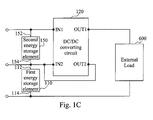
- FIG. 1 C schematically illustrates a power converter according to yet another embodiment of the present invention.
- the second terminal 154 of the second energy storage element 150 is electrically connected to the first terminal 112 of the first energy storage element 110.
- the second energy storage element 150 and the first energy storage element 110 are electrically connected; that is, these two energy storage elements are electrically non-isolated.
- the voltage across the second energy storage element 150 is greater than the voltage across the first energy storage element 110.
- the first energy storage element 110 may be a rechargeable battery or a super capacitor.
- the second energy storage element 150 may be a rechargeable battery or a super capacitor; however, the present invention is not limited thereto, and the skilled in the art may choose suitable elements for implementing the present disclosure.
- embodiments of the present invention further provide a circuit structure which is illustrated in Figure 2A .
- the power converter comprises a DC/DC converting circuit 120, a first energy storage element 110 and a switch 130.
- the DC/DC converting circuit 120 comprises a first output terminal OUT1 and a second output terminal OUT2
- the first energy storage element 110 comprises a first terminal 112 and a second terminal 114
- the switch 130 comprises a first connecting terminal 132, a second connecting terminal 134 and a third connecting terminal 136.
- the first output terminal OUT1 of the DC/DC converting circuit 120 is electrically connected to one terminal of the external load 600
- the first terminal 112 of the first energy storage element 110 is electrically connected to the second output terminal OUT2 of the DC/DC converting circuit 120
- the first connecting terminal 132 of the switch 130 is electrically connected to the second output terminal OUT2 of the DC/DC converting circuit 120
- the second connecting terminal 134 of the switch 130 is electrically connected to the second terminal 114 of the first energy storage element 110
- the third connecting terminal 136 of the switch 130 is electrically connected to the other terminal of the external load 600.
- the DC/DC converting circuit 120 is configured to provide a variable electric power, and the power converter provides a two-stage continuous power supply to the external load 600 by the switching operation of the switch 130. In this way, since the power converter provides a two-stage continuous power supply to the external load 600, the external load 600 can tolerate the supply voltage provided by the first energy storage element 110, and after that, the first energy storage element 110 and the DC/DC converting circuit 120 are used jointly to provide power supply for the external load 600; consequently, the problem of out-of-control current on the external load 600 can be avoided.
- the above-mentioned provision of a two-stage continuous power supply by the switching operation of the switch 130 is exemplified below.
- the power converter When the third connecting terminal 136 and the first connecting terminal 132 of the switch 130 are electrically connected, the power converter provides the power supply for the external load 600 by use of the variable electric power; and when the third connecting terminal 136 and the second connecting terminal 134 of the switch 130 are electrically connected, the power converter provides the power supply for the external load 600 according to the DC/DC converting circuit and the first energy storage element.
- embodiments of the present invention further comprise a controller 140 in the circuit structure illustrated in Figure 2A .
- controller 140 Such an implementation is detailed below.
- the power converter further comprises a controller 140 which, in turn, comprises a detection terminal 142 and a control terminal 144.
- the detection terminal 142 is configured to detect the voltage across the external load 600.
- the control terminal 144 is electrically connected to the switch 130.
- a predetermined voltage for example, a default voltage
- the control terminal 144 outputs a control signal to the switch 130, thereby allowing the second connecting terminal 134 and the third connecting terminal 136 of the switch 130 to be electrically connected
- the control terminal 144 outputs another control signal to the switch 130, thereby allowing the first connecting terminal 132 and the third connecting terminal 136 of the switch 130 to be electrically connected.
- the first terminal 112 of the first energy storage element 110 is electrically connected to the first input terminal IN1 of the DC/DC converting circuit 120, and the second terminal 114 of the first energy storage element 110 is electrically connected to the second input terminal IN2 of the DC/DC converting circuit 120.
- the power converter of Figure 2B further comprises a second energy storage element 150 which, in turn, comprises a first terminal 152 and a second terminal 154.
- the first terminal 152 is electrically connected to the first input terminal IN1 of the DC/DC converting circuit 120
- the second terminal 154 is electrically connected to the second input terminal IN2 of the DC/DC converting circuit 120.
- the second energy storage element 150 can be used as the input electric source for the DC/DC converting circuit 120; additionally, the second energy storage element 150 and the first energy storage element 110 are electrically isolated.
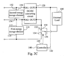
- FIG. 2C schematically illustrates a power converter according to yet another embodiment of the present invention.
- the second terminal 154 of the second energy storage element 150 is electrically connected to the first terminal 112 of the first energy storage element 110.
- the second energy storage element 150 and the first energy storage element 110 are electrically connected; that is, these two energy storage elements are electrically non-isolated.
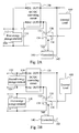
- FIG. 2D shows the circuit of a power converter of the DC/DC converting circuit 120 of Figure 2B .
- the DC/DC converting circuit 120 may be a buck circuit which comprises a power switch S, a first diode D1, an inductor L, a capacitor C and a second diode D2.
- the power switch S has one terminal electrically connected to the first terminal 152 of the second energy storage element 150, the anode of the first diode D1 is electrically connected to the second terminal 154 of the second energy storage element 150, the cathode of the first diode D1 is electrically connected to the other terminal of the power switch S, one terminal of the inductor L is electrically connected to the cathode of the first diode D1, one terminal of the capacitor C is electrically connected to the other terminal of the inductor L, the other terminal of the capacitor C is electrically connected to the second terminal 154 of the second energy storage element 150, the anode of the second diode D2 is electrically connected to the other terminal of the inductor L, and the cathode of the second diode D2 is electrically connected to external load 600.
- the voltage across the second energy storage element 150 is greater than the voltage across the first energy storage element 110.
- the first energy storage element 110 may be a rechargeable battery or a super capacitor.
- the second energy storage element 120 may be a rechargeable battery or a super capacitor; however, the present invention is not limited thereto, and the skilled in the art may choose suitable elements for implementing the present disclosure.
- Figure 3 is a line graph illustrating the change in the voltage across an external load connected to a power converter according to another embodiment of the present invention.
- the controller 140 when the controller 140 detects that the voltage across the external load 600 is equal to or greater than the supply voltage of the first energy storage element 110 (for example, when the voltage across the load is 420V), the controller 140 outputs a control signal to the switch 130, and the switch 130, when receiving the control signal, switches from the first input terminal 132 to the second input terminal 134, thereby allowing the second terminal 114 of the first energy storage element 110 and the other terminal of the external load 600 to be electrically connected, and hence, the first energy storage element 110 together with the DC/DC converting circuit 120 provide the power supply for the external load 600.
- the first energy storage element 110 together with the DC/DC converting circuit 120 only provide the power supply for the external load 600 after it is determined that the external load 600 can tolerate the supply voltage provided by the first energy storage element 110; consequently, the problem of the out-of-control current on the external load 600 can be avoided.
- the power converter of the present invention adopts a staged strategy while supplying electricity to the external load.
- the DC/DC converting circuit 120 alone is used to provide power supply for the external load 600, thereby allowing load the voltage across the external to increase from the voltage range of 0V to 420V.
- the DC/DC converting circuit 120 and the first energy storage element 110 are serially connected so that they supply electricity to the external load 600 jointly, thereby allowing the voltage across the external load to continuously rise from 420V to 800V.
- the electric power outputted by the DC/DC converting circuit 120 is not necessarily equal to the electric power required by the external load 600.
- the electric power from the DC/DC converting circuit 120 is used as a portion of the electric power required by the external load 600; consequently, it is possible to decrease the power level of the DC/DC converting circuit 120 and reduce the design cost thereof.
- the present invention further provides a method for providing a power supply by a power converter.
- the power converter comprises a DC/DC converting circuit and a first energy storage element serially connected to the output terminal of the DC/DC converting circuit.
- Figure 1A an example of a power converter to which the method for providing the power supply by the power converter is applied.
- Said method for providing the power supply by the power converter comprises the following steps: providing a variable electric power through the DC/DC converting circuit; providing a switch, of which the first connecting terminal and the third connecting terminal is electrically connected, thereby allowing the DC/DC converting circuit solelyto provide the power supply to the external load; detecting the voltage across the external load; and when the voltage across the external load is equal to or greater than a predetermined voltage (for example, a default voltage), the third connecting terminal of the switch is switched to electrically connect with the second connecting terminal, thereby allowing the DC/DC converting circuit together with the first energy storage element to provide the power supply for the external load.
- a predetermined voltage for example, a default voltage
- the method for providing the power supply by the power converter can charge the external load 600 by serially connecting the first energy storage element 110 and the output terminal of the DC/DC converting circuit 120 at the same time. Accordingly, the variable electric power provided by the DC/DC converting circuit 120 is not necessarily equal to the power required by the external load 600; in fact, the variable electric power provided by the DC/DC converting circuit 120 is less than the power required by the external load 600. Therefore, the method for providing the power supply by the power converter according to embodiments of the present invention may decrease the power level of the DC/DC converting circuit 120, and decrease the cost and size of the DC/DC converting circuit 120. Moreover, the power level of the DC/DC converting circuit 120 may be lowered.
- a predetermined voltage for example, a default voltage
- said process steps are intended to ensure that it is only when the external load 600 can tolerate the supply voltage provided by the first energy storage element 110 that the first energy storage element 110 and the DC/DC converting circuit 120 will be serially connected to thereby provide power supply for the external load 600 jointly; consequently, the problem of the current on the external load 600 getting out of control may be avoided.
- the first energy storage element 110 can be a rechargeable battery or a super capacitor; however, the present invention is not limited thereto, and persons having ordinary skill in the art may choose suitable elements for implementing the present disclosure.
- the method for providing the power supply by the power converter further comprises the following step(s): using the controller to detect the voltage across the external load 600, wherein when the controller 140 detects that the voltage across the external load 600 is equal to or greater than a predetermined voltage (for example, a default voltage), the controller 140 outputs a control signal to the switch 130, and when switch 130 receives the control signal, it switches the third connecting terminal 136 to be electrically connected to the second connecting terminal 134.
- a predetermined voltage for example, a default voltage
- the first energy storage element 110 and the output portion of the DC/DC converting circuit 120 are serially connected, and the first energy storage element 110 together with the DC/DC converting circuit 120 provide the power supply to the external load 600.
- the controller 140 to detect the voltage across the external load 600 and to control the switch 130 depending on the result of this detection, it is possible to more precisely prevent the current on the external load 600 from getting out of control.
- the above-described detection method using the controller 140 to detect the voltage across the external load 600 is provided for illustration purposes, and in other embodiments, it is possible to detect other electrical parameters or signals, and indirectly detect the voltage across the load using said other electrical parameters or signals, and these embodiments also fall within the principles and spirit of the present invention.
- the method for providing the power supply by the power converter can be performed with software, hardware, and/or firmware.
- the implementer may opt for a mainly hardware and/or firmware implementation; alternatively, if flexibility is paramount, the implementer may opt for a mainly software implementation; or, yet again alternatively, the implementer may opt for some combination of hardware, software, and/or firmware.
- optical aspects of implementations will typically employ optically oriented hardware, software, and or firmware.
- the embodiment of the present invention provides a power converter and a method for providing a power supply by the power converter, so as to address the problems faced in the prior art related to the significant size and cost of the power converter when the power required by a load is large.
Landscapes
- Engineering & Computer Science (AREA)
- Power Engineering (AREA)
- Transportation (AREA)
- Mechanical Engineering (AREA)
- Life Sciences & Earth Sciences (AREA)
- Sustainable Development (AREA)
- Sustainable Energy (AREA)
- Dc-Dc Converters (AREA)
- Inverter Devices (AREA)
Applications Claiming Priority (1)
| Application Number | Priority Date | Filing Date | Title |
|---|---|---|---|
| CN201310218924.4A CN104218795B (zh) | 2013-06-04 | 2013-06-04 | 功率变换器及其供电方法 |
Publications (3)
| Publication Number | Publication Date |
|---|---|
| EP2811630A2 true EP2811630A2 (de) | 2014-12-10 |
| EP2811630A3 EP2811630A3 (de) | 2015-09-23 |
| EP2811630B1 EP2811630B1 (de) | 2022-04-20 |
Family
ID=50841692
Family Applications (1)
| Application Number | Title | Priority Date | Filing Date |
|---|---|---|---|
| EP14170987.3A Active EP2811630B1 (de) | 2013-06-04 | 2014-06-03 | Stromwandler und Stromversorgungsverfahren dafür |
Country Status (4)
| Country | Link |
|---|---|
| US (1) | US9627965B2 (de) |
| EP (1) | EP2811630B1 (de) |
| CN (1) | CN104218795B (de) |
| TW (1) | TWI485543B (de) |
Families Citing this family (7)
| Publication number | Priority date | Publication date | Assignee | Title |
|---|---|---|---|---|
| US20160241026A1 (en) * | 2015-02-15 | 2016-08-18 | Skyworks Solutions, Inc. | Reconfigurable power supply cell for efficient boost and buck-boost applications |
| DE102016200769B4 (de) * | 2016-01-21 | 2024-08-22 | Bayerische Motoren Werke Aktiengesellschaft | Verbesserte Stromquellenanordnung mit mehreren Stromquellen |
| DE102016122383A1 (de) * | 2016-11-21 | 2018-06-14 | Rutronik Elektronische Bauelemente Gmbh | Hybrides Energiespeichersystem |
| US11616441B2 (en) | 2018-09-21 | 2023-03-28 | Universidad Técnica Federico Santa María | Transformerless partial power converter (PPC) for the DC-DC stage of rapid-charging stations for electric vehicles (EV) |
| JP7465432B2 (ja) * | 2020-07-10 | 2024-04-11 | 株式会社オートネットワーク技術研究所 | 変換装置 |
| KR20230083555A (ko) * | 2021-12-03 | 2023-06-12 | 주식회사 엘지에너지솔루션 | Dc-dc 변환을 수행하는 전력 변환 장치 및 이를 포함하는 에너지 저장 시스템 |
| WO2024229170A1 (en) * | 2023-05-02 | 2024-11-07 | Our Next Energy, Inc. | Battery packs with partial-power processing dc-dc converters |
Family Cites Families (17)
| Publication number | Priority date | Publication date | Assignee | Title |
|---|---|---|---|---|
| US4479083B1 (en) * | 1982-09-30 | 1998-09-01 | Vanner Weldon Inc | DC power system having battery voltage equalizer circuit |
| US6101108A (en) * | 1997-06-06 | 2000-08-08 | Technical Witts, Inc. | Regulated input current, regulated output voltage power converter |
| JP3776348B2 (ja) * | 2001-12-10 | 2006-05-17 | 本田技研工業株式会社 | 車両用電源装置 |
| JP4468708B2 (ja) * | 2004-01-16 | 2010-05-26 | 三菱電機株式会社 | 電源装置 |
| CN100355194C (zh) * | 2004-03-08 | 2007-12-12 | 耿宪温 | 一种开关电源变换器的拓扑结构 |
| US7173344B2 (en) * | 2004-04-19 | 2007-02-06 | Tai-Her Yang | Series & parallel combined dual power drive system |
| EP2006974B1 (de) * | 2006-03-15 | 2016-06-01 | NEC Corporation | Ladevorrichtung und lade-/entladevorrichtung |
| JP4893368B2 (ja) * | 2007-02-28 | 2012-03-07 | パナソニック株式会社 | 電源装置 |
| US8450977B2 (en) * | 2007-12-20 | 2013-05-28 | O2Micro, Inc. | Power management systems with charge pumps |
| CN201789415U (zh) * | 2009-11-17 | 2011-04-06 | 中兴通讯股份有限公司 | 一种用于脉冲型负载的供电装置 |
| TW201135392A (en) * | 2010-04-15 | 2011-10-16 | Advanced Power Electronics Corp | Buck converter |
| TWI407668B (zh) * | 2010-07-09 | 2013-09-01 | Leadtrend Tech Corp | 電源供應器以及抑制電源供應器之輸出電壓波動的方法 |
| CA2746304A1 (fr) * | 2011-07-15 | 2013-01-15 | Hydro-Quebec | Systeme de recharge rapide multi-niveaux avec batteries de puissance imbriquees |
| TW201308856A (zh) * | 2011-08-04 | 2013-02-16 | Shamrock Micro Devices Corp | 開關式電源供應器以及於一輸出電源端提供一輸出電壓之控制方法 |
| EP2573899A1 (de) * | 2011-09-22 | 2013-03-27 | Siemens Aktiengesellschaft | Energieversorgungseinheit mit seriellem Hochsetzsteller |
| CN102545709B (zh) * | 2012-01-19 | 2015-03-11 | 无锡联动太阳能科技有限公司 | 一种适用于太阳能发电装置的能量优化装置 |
| CN202818129U (zh) * | 2012-08-28 | 2013-03-20 | 卢咸进 | 一种dsp控制的可调式大功率分布式直流电源 |
-
2013
- 2013-06-04 CN CN201310218924.4A patent/CN104218795B/zh active Active
- 2013-06-27 TW TW102122893A patent/TWI485543B/zh active
-
2014
- 2014-06-03 EP EP14170987.3A patent/EP2811630B1/de active Active
- 2014-06-03 US US14/295,090 patent/US9627965B2/en active Active
Non-Patent Citations (1)
| Title |
|---|
| None |
Also Published As
| Publication number | Publication date |
|---|---|
| US9627965B2 (en) | 2017-04-18 |
| US20140354058A1 (en) | 2014-12-04 |
| EP2811630B1 (de) | 2022-04-20 |
| EP2811630A3 (de) | 2015-09-23 |
| TW201447531A (zh) | 2014-12-16 |
| CN104218795B (zh) | 2017-09-22 |
| CN104218795A (zh) | 2014-12-17 |
| TWI485543B (zh) | 2015-05-21 |
Similar Documents
| Publication | Publication Date | Title |
|---|---|---|
| US9627965B2 (en) | Power converter and power supplying method thereof | |
| CN102064592B (zh) | 一种大功率电池装置 | |
| EP3506457B1 (de) | Ladesystem mit niedrigem standby-energieverbrauch und verfahren zur steuerung eines solchen systems | |
| CN105915156B (zh) | 带有功率优化器的光伏发电系统 | |
| KR101865246B1 (ko) | 전기자동차용 충방전 장치 | |
| US10056847B2 (en) | Hybrid power conversion system and method of determining efficiency using the same | |
| CN110149044A (zh) | 两级式变换器及其启动方法、llc变换器和应用系统 | |
| CN101789690B (zh) | 一种ups前级升压装置 | |
| WO2013129231A1 (ja) | 電源装置 | |
| CN103378736A (zh) | 供电设备及其操作方法和包括供电设备的太阳能发电系统 | |
| US20140268962A1 (en) | Hybrid dc/ac inverter | |
| CN215120607U (zh) | 一种直流充电桩功率拓扑及直流充电桩 | |
| CN116388350B (zh) | 充电控制方法、储能设备和可读存储介质 | |
| JP2009207328A (ja) | 電源装置 | |
| JP2014117086A (ja) | 系統連系システム | |
| US20140078801A1 (en) | Advanced dc voltage adjustment using switched capacitors | |
| CN111746318A (zh) | 应用于电动车的电池模组的充电电路 | |
| JP5997225B2 (ja) | 太陽光インバータ | |
| US11152872B2 (en) | DC to AC converter and control method thereof | |
| EP2810817B1 (de) | Stromversorgungssystem und Verfahren zur Umwandlung von Strom davon | |
| CN113794364A (zh) | 供电系统及其控制方法 | |
| CN211296551U (zh) | 兼容交直流输出控制电路及车载设备 | |
| CN212708993U (zh) | 应用于电动车的电池模组的充电电路 | |
| JP5849517B2 (ja) | 電源システム | |
| TWI861718B (zh) | 諧振轉換器及諧振轉換電路系統 |
Legal Events
| Date | Code | Title | Description |
|---|---|---|---|
| PUAI | Public reference made under article 153(3) epc to a published international application that has entered the european phase |
Free format text: ORIGINAL CODE: 0009012 |
|
| 17P | Request for examination filed |
Effective date: 20140603 |
|
| AK | Designated contracting states |
Kind code of ref document: A2 Designated state(s): AL AT BE BG CH CY CZ DE DK EE ES FI FR GB GR HR HU IE IS IT LI LT LU LV MC MK MT NL NO PL PT RO RS SE SI SK SM TR |
|
| AX | Request for extension of the european patent |
Extension state: BA ME |
|
| PUAL | Search report despatched |
Free format text: ORIGINAL CODE: 0009013 |
|
| AK | Designated contracting states |
Kind code of ref document: A3 Designated state(s): AL AT BE BG CH CY CZ DE DK EE ES FI FR GB GR HR HU IE IS IT LI LT LU LV MC MK MT NL NO PL PT RO RS SE SI SK SM TR |
|
| AX | Request for extension of the european patent |
Extension state: BA ME |
|
| RIC1 | Information provided on ipc code assigned before grant |
Ipc: H02M 1/00 20070101AFI20150814BHEP |
|
| RBV | Designated contracting states (corrected) |
Designated state(s): AL AT BE BG CH CY CZ DE DK EE ES FI FR GB GR HR HU IE IS IT LI LT LU LV MC MK MT NL NO PL PT RO RS SE SI SK SM TR |
|
| STAA | Information on the status of an ep patent application or granted ep patent |
Free format text: STATUS: EXAMINATION IS IN PROGRESS |
|
| 17Q | First examination report despatched |
Effective date: 20210325 |
|
| GRAP | Despatch of communication of intention to grant a patent |
Free format text: ORIGINAL CODE: EPIDOSNIGR1 |
|
| STAA | Information on the status of an ep patent application or granted ep patent |
Free format text: STATUS: GRANT OF PATENT IS INTENDED |
|
| INTG | Intention to grant announced |
Effective date: 20220201 |
|
| GRAS | Grant fee paid |
Free format text: ORIGINAL CODE: EPIDOSNIGR3 |
|
| GRAA | (expected) grant |
Free format text: ORIGINAL CODE: 0009210 |
|
| STAA | Information on the status of an ep patent application or granted ep patent |
Free format text: STATUS: THE PATENT HAS BEEN GRANTED |
|
| AK | Designated contracting states |
Kind code of ref document: B1 Designated state(s): AL AT BE BG CH CY CZ DE DK EE ES FI FR GB GR HR HU IE IS IT LI LT LU LV MC MK MT NL NO PL PT RO RS SE SI SK SM TR |
|
| REG | Reference to a national code |
Ref country code: GB Ref legal event code: FG4D |
|
| REG | Reference to a national code |
Ref country code: CH Ref legal event code: EP |
|
| REG | Reference to a national code |
Ref country code: DE Ref legal event code: R096 Ref document number: 602014083305 Country of ref document: DE |
|
| REG | Reference to a national code |
Ref country code: IE Ref legal event code: FG4D |
|
| REG | Reference to a national code |
Ref country code: AT Ref legal event code: REF Ref document number: 1485979 Country of ref document: AT Kind code of ref document: T Effective date: 20220515 |
|
| REG | Reference to a national code |
Ref country code: NL Ref legal event code: FP |
|
| REG | Reference to a national code |
Ref country code: LT Ref legal event code: MG9D |
|
| REG | Reference to a national code |
Ref country code: AT Ref legal event code: MK05 Ref document number: 1485979 Country of ref document: AT Kind code of ref document: T Effective date: 20220420 |
|
| PG25 | Lapsed in a contracting state [announced via postgrant information from national office to epo] |
Ref country code: SE Free format text: LAPSE BECAUSE OF FAILURE TO SUBMIT A TRANSLATION OF THE DESCRIPTION OR TO PAY THE FEE WITHIN THE PRESCRIBED TIME-LIMIT Effective date: 20220420 Ref country code: PT Free format text: LAPSE BECAUSE OF FAILURE TO SUBMIT A TRANSLATION OF THE DESCRIPTION OR TO PAY THE FEE WITHIN THE PRESCRIBED TIME-LIMIT Effective date: 20220822 Ref country code: NO Free format text: LAPSE BECAUSE OF FAILURE TO SUBMIT A TRANSLATION OF THE DESCRIPTION OR TO PAY THE FEE WITHIN THE PRESCRIBED TIME-LIMIT Effective date: 20220720 Ref country code: LT Free format text: LAPSE BECAUSE OF FAILURE TO SUBMIT A TRANSLATION OF THE DESCRIPTION OR TO PAY THE FEE WITHIN THE PRESCRIBED TIME-LIMIT Effective date: 20220420 Ref country code: HR Free format text: LAPSE BECAUSE OF FAILURE TO SUBMIT A TRANSLATION OF THE DESCRIPTION OR TO PAY THE FEE WITHIN THE PRESCRIBED TIME-LIMIT Effective date: 20220420 Ref country code: GR Free format text: LAPSE BECAUSE OF FAILURE TO SUBMIT A TRANSLATION OF THE DESCRIPTION OR TO PAY THE FEE WITHIN THE PRESCRIBED TIME-LIMIT Effective date: 20220721 Ref country code: FI Free format text: LAPSE BECAUSE OF FAILURE TO SUBMIT A TRANSLATION OF THE DESCRIPTION OR TO PAY THE FEE WITHIN THE PRESCRIBED TIME-LIMIT Effective date: 20220420 Ref country code: ES Free format text: LAPSE BECAUSE OF FAILURE TO SUBMIT A TRANSLATION OF THE DESCRIPTION OR TO PAY THE FEE WITHIN THE PRESCRIBED TIME-LIMIT Effective date: 20220420 Ref country code: BG Free format text: LAPSE BECAUSE OF FAILURE TO SUBMIT A TRANSLATION OF THE DESCRIPTION OR TO PAY THE FEE WITHIN THE PRESCRIBED TIME-LIMIT Effective date: 20220720 Ref country code: AT Free format text: LAPSE BECAUSE OF FAILURE TO SUBMIT A TRANSLATION OF THE DESCRIPTION OR TO PAY THE FEE WITHIN THE PRESCRIBED TIME-LIMIT Effective date: 20220420 |
|
| PG25 | Lapsed in a contracting state [announced via postgrant information from national office to epo] |
Ref country code: RS Free format text: LAPSE BECAUSE OF FAILURE TO SUBMIT A TRANSLATION OF THE DESCRIPTION OR TO PAY THE FEE WITHIN THE PRESCRIBED TIME-LIMIT Effective date: 20220420 Ref country code: PL Free format text: LAPSE BECAUSE OF FAILURE TO SUBMIT A TRANSLATION OF THE DESCRIPTION OR TO PAY THE FEE WITHIN THE PRESCRIBED TIME-LIMIT Effective date: 20220420 Ref country code: LV Free format text: LAPSE BECAUSE OF FAILURE TO SUBMIT A TRANSLATION OF THE DESCRIPTION OR TO PAY THE FEE WITHIN THE PRESCRIBED TIME-LIMIT Effective date: 20220420 Ref country code: IS Free format text: LAPSE BECAUSE OF FAILURE TO SUBMIT A TRANSLATION OF THE DESCRIPTION OR TO PAY THE FEE WITHIN THE PRESCRIBED TIME-LIMIT Effective date: 20220820 |
|
| REG | Reference to a national code |
Ref country code: DE Ref legal event code: R097 Ref document number: 602014083305 Country of ref document: DE |
|
| PG25 | Lapsed in a contracting state [announced via postgrant information from national office to epo] |
Ref country code: SM Free format text: LAPSE BECAUSE OF FAILURE TO SUBMIT A TRANSLATION OF THE DESCRIPTION OR TO PAY THE FEE WITHIN THE PRESCRIBED TIME-LIMIT Effective date: 20220420 Ref country code: SK Free format text: LAPSE BECAUSE OF FAILURE TO SUBMIT A TRANSLATION OF THE DESCRIPTION OR TO PAY THE FEE WITHIN THE PRESCRIBED TIME-LIMIT Effective date: 20220420 Ref country code: RO Free format text: LAPSE BECAUSE OF FAILURE TO SUBMIT A TRANSLATION OF THE DESCRIPTION OR TO PAY THE FEE WITHIN THE PRESCRIBED TIME-LIMIT Effective date: 20220420 Ref country code: MC Free format text: LAPSE BECAUSE OF FAILURE TO SUBMIT A TRANSLATION OF THE DESCRIPTION OR TO PAY THE FEE WITHIN THE PRESCRIBED TIME-LIMIT Effective date: 20220420 Ref country code: EE Free format text: LAPSE BECAUSE OF FAILURE TO SUBMIT A TRANSLATION OF THE DESCRIPTION OR TO PAY THE FEE WITHIN THE PRESCRIBED TIME-LIMIT Effective date: 20220420 Ref country code: DK Free format text: LAPSE BECAUSE OF FAILURE TO SUBMIT A TRANSLATION OF THE DESCRIPTION OR TO PAY THE FEE WITHIN THE PRESCRIBED TIME-LIMIT Effective date: 20220420 Ref country code: CZ Free format text: LAPSE BECAUSE OF FAILURE TO SUBMIT A TRANSLATION OF THE DESCRIPTION OR TO PAY THE FEE WITHIN THE PRESCRIBED TIME-LIMIT Effective date: 20220420 |
|
| REG | Reference to a national code |
Ref country code: CH Ref legal event code: PL |
|
| REG | Reference to a national code |
Ref country code: BE Ref legal event code: MM Effective date: 20220630 |
|
| PLBE | No opposition filed within time limit |
Free format text: ORIGINAL CODE: 0009261 |
|
| STAA | Information on the status of an ep patent application or granted ep patent |
Free format text: STATUS: NO OPPOSITION FILED WITHIN TIME LIMIT |
|
| 26N | No opposition filed |
Effective date: 20230123 |
|
| PG25 | Lapsed in a contracting state [announced via postgrant information from national office to epo] |
Ref country code: AL Free format text: LAPSE BECAUSE OF FAILURE TO SUBMIT A TRANSLATION OF THE DESCRIPTION OR TO PAY THE FEE WITHIN THE PRESCRIBED TIME-LIMIT Effective date: 20220420 |
|
| PG25 | Lapsed in a contracting state [announced via postgrant information from national office to epo] |
Ref country code: LU Free format text: LAPSE BECAUSE OF NON-PAYMENT OF DUE FEES Effective date: 20220603 Ref country code: LI Free format text: LAPSE BECAUSE OF NON-PAYMENT OF DUE FEES Effective date: 20220630 Ref country code: IE Free format text: LAPSE BECAUSE OF NON-PAYMENT OF DUE FEES Effective date: 20220603 Ref country code: FR Free format text: LAPSE BECAUSE OF NON-PAYMENT OF DUE FEES Effective date: 20220620 Ref country code: CH Free format text: LAPSE BECAUSE OF NON-PAYMENT OF DUE FEES Effective date: 20220630 |
|
| PG25 | Lapsed in a contracting state [announced via postgrant information from national office to epo] |
Ref country code: SI Free format text: LAPSE BECAUSE OF FAILURE TO SUBMIT A TRANSLATION OF THE DESCRIPTION OR TO PAY THE FEE WITHIN THE PRESCRIBED TIME-LIMIT Effective date: 20220420 Ref country code: BE Free format text: LAPSE BECAUSE OF NON-PAYMENT OF DUE FEES Effective date: 20220630 |
|
| PG25 | Lapsed in a contracting state [announced via postgrant information from national office to epo] |
Ref country code: IT Free format text: LAPSE BECAUSE OF FAILURE TO SUBMIT A TRANSLATION OF THE DESCRIPTION OR TO PAY THE FEE WITHIN THE PRESCRIBED TIME-LIMIT Effective date: 20220420 |
|
| PG25 | Lapsed in a contracting state [announced via postgrant information from national office to epo] |
Ref country code: HU Free format text: LAPSE BECAUSE OF FAILURE TO SUBMIT A TRANSLATION OF THE DESCRIPTION OR TO PAY THE FEE WITHIN THE PRESCRIBED TIME-LIMIT; INVALID AB INITIO Effective date: 20140603 |
|
| PG25 | Lapsed in a contracting state [announced via postgrant information from national office to epo] |
Ref country code: MK Free format text: LAPSE BECAUSE OF FAILURE TO SUBMIT A TRANSLATION OF THE DESCRIPTION OR TO PAY THE FEE WITHIN THE PRESCRIBED TIME-LIMIT Effective date: 20220420 Ref country code: CY Free format text: LAPSE BECAUSE OF FAILURE TO SUBMIT A TRANSLATION OF THE DESCRIPTION OR TO PAY THE FEE WITHIN THE PRESCRIBED TIME-LIMIT Effective date: 20220420 |
|
| PG25 | Lapsed in a contracting state [announced via postgrant information from national office to epo] |
Ref country code: TR Free format text: LAPSE BECAUSE OF FAILURE TO SUBMIT A TRANSLATION OF THE DESCRIPTION OR TO PAY THE FEE WITHIN THE PRESCRIBED TIME-LIMIT Effective date: 20220420 |
|
| PG25 | Lapsed in a contracting state [announced via postgrant information from national office to epo] |
Ref country code: MT Free format text: LAPSE BECAUSE OF FAILURE TO SUBMIT A TRANSLATION OF THE DESCRIPTION OR TO PAY THE FEE WITHIN THE PRESCRIBED TIME-LIMIT Effective date: 20220420 |
|
| PG25 | Lapsed in a contracting state [announced via postgrant information from national office to epo] |
Ref country code: BG Free format text: LAPSE BECAUSE OF FAILURE TO SUBMIT A TRANSLATION OF THE DESCRIPTION OR TO PAY THE FEE WITHIN THE PRESCRIBED TIME-LIMIT Effective date: 20220420 |
|
| PG25 | Lapsed in a contracting state [announced via postgrant information from national office to epo] |
Ref country code: BG Free format text: LAPSE BECAUSE OF FAILURE TO SUBMIT A TRANSLATION OF THE DESCRIPTION OR TO PAY THE FEE WITHIN THE PRESCRIBED TIME-LIMIT Effective date: 20220420 |
|
| PGFP | Annual fee paid to national office [announced via postgrant information from national office to epo] |
Ref country code: NL Payment date: 20250409 Year of fee payment: 12 |
|
| PGFP | Annual fee paid to national office [announced via postgrant information from national office to epo] |
Ref country code: DE Payment date: 20250402 Year of fee payment: 12 |
|
| PGFP | Annual fee paid to national office [announced via postgrant information from national office to epo] |
Ref country code: GB Payment date: 20250401 Year of fee payment: 12 |