EP4239418A1 - Wasserfahrzeug, kurssteuerungsverfahren, kurssteuerungsvorrichtung und programm - Google Patents
Wasserfahrzeug, kurssteuerungsverfahren, kurssteuerungsvorrichtung und programm Download PDFInfo
- Publication number
- EP4239418A1 EP4239418A1 EP21900632.7A EP21900632A EP4239418A1 EP 4239418 A1 EP4239418 A1 EP 4239418A1 EP 21900632 A EP21900632 A EP 21900632A EP 4239418 A1 EP4239418 A1 EP 4239418A1
- Authority
- EP
- European Patent Office
- Prior art keywords
- heading
- gain
- pid control
- target
- unit
- Prior art date
- Legal status (The legal status is an assumption and is not a legal conclusion. Google has not performed a legal analysis and makes no representation as to the accuracy of the status listed.)
- Withdrawn
Links
Images


Classifications
-
- B—PERFORMING OPERATIONS; TRANSPORTING
- B63—SHIPS OR OTHER WATERBORNE VESSELS; RELATED EQUIPMENT
- B63H—MARINE PROPULSION OR STEERING
- B63H25/00—Steering; Slowing-down otherwise than by use of propulsive elements; Dynamic anchoring, i.e. positioning vessels by means of main or auxiliary propulsive elements
- B63H25/02—Initiating means for steering, for slowing down, otherwise than by use of propulsive elements, or for dynamic anchoring
- B63H25/04—Initiating means for steering, for slowing down, otherwise than by use of propulsive elements, or for dynamic anchoring automatic, e.g. reacting to compass
-
- B—PERFORMING OPERATIONS; TRANSPORTING
- B63—SHIPS OR OTHER WATERBORNE VESSELS; RELATED EQUIPMENT
- B63H—MARINE PROPULSION OR STEERING
- B63H25/00—Steering; Slowing-down otherwise than by use of propulsive elements; Dynamic anchoring, i.e. positioning vessels by means of main or auxiliary propulsive elements
- B63H25/06—Steering by rudders
- B63H25/38—Rudders
-
- G—PHYSICS
- G05—CONTROLLING; REGULATING
- G05D—SYSTEMS FOR CONTROLLING OR REGULATING NON-ELECTRIC VARIABLES
- G05D1/00—Control of position, course, altitude or attitude of land, water, air or space vehicles, e.g. using automatic pilots
- G05D1/02—Control of position or course in two dimensions
- G05D1/0206—Control of position or course in two dimensions specially adapted to water vehicles
-
- G—PHYSICS
- G05—CONTROLLING; REGULATING
- G05D—SYSTEMS FOR CONTROLLING OR REGULATING NON-ELECTRIC VARIABLES
- G05D1/00—Control of position, course, altitude or attitude of land, water, air or space vehicles, e.g. using automatic pilots
- G05D1/40—Control within particular dimensions
- G05D1/43—Control of position or course in two dimensions
-
- G—PHYSICS
- G05—CONTROLLING; REGULATING
- G05D—SYSTEMS FOR CONTROLLING OR REGULATING NON-ELECTRIC VARIABLES
- G05D1/00—Control of position, course, altitude or attitude of land, water, air or space vehicles, e.g. using automatic pilots
- G05D1/60—Intended control result
- G05D1/646—Following a predefined trajectory, e.g. a line marked on the floor or a flight path
-
- B—PERFORMING OPERATIONS; TRANSPORTING
- B63—SHIPS OR OTHER WATERBORNE VESSELS; RELATED EQUIPMENT
- B63B—SHIPS OR OTHER WATERBORNE VESSELS; EQUIPMENT FOR SHIPPING
- B63B79/00—Monitoring properties or operating parameters of vessels in operation
- B63B79/40—Monitoring properties or operating parameters of vessels in operation for controlling the operation of vessels, e.g. monitoring their speed, routing or maintenance schedules
-
- B—PERFORMING OPERATIONS; TRANSPORTING
- B63—SHIPS OR OTHER WATERBORNE VESSELS; RELATED EQUIPMENT
- B63H—MARINE PROPULSION OR STEERING
- B63H25/00—Steering; Slowing-down otherwise than by use of propulsive elements; Dynamic anchoring, i.e. positioning vessels by means of main or auxiliary propulsive elements
- B63H25/02—Initiating means for steering, for slowing down, otherwise than by use of propulsive elements, or for dynamic anchoring
- B63H25/04—Initiating means for steering, for slowing down, otherwise than by use of propulsive elements, or for dynamic anchoring automatic, e.g. reacting to compass
- B63H2025/045—Initiating means for steering, for slowing down, otherwise than by use of propulsive elements, or for dynamic anchoring automatic, e.g. reacting to compass making use of satellite radio beacon positioning systems, e.g. the Global Positioning System [GPS]
-
- G—PHYSICS
- G05—CONTROLLING; REGULATING
- G05D—SYSTEMS FOR CONTROLLING OR REGULATING NON-ELECTRIC VARIABLES
- G05D2105/00—Specific applications of the controlled vehicles
- G05D2105/20—Specific applications of the controlled vehicles for transportation
- G05D2105/22—Specific applications of the controlled vehicles for transportation of humans
- G05D2105/24—Specific applications of the controlled vehicles for transportation of humans personal mobility devices
-
- G—PHYSICS
- G05—CONTROLLING; REGULATING
- G05D—SYSTEMS FOR CONTROLLING OR REGULATING NON-ELECTRIC VARIABLES
- G05D2107/00—Specific environments of the controlled vehicles
- G05D2107/25—Aquatic environments
-
- G—PHYSICS
- G05—CONTROLLING; REGULATING
- G05D—SYSTEMS FOR CONTROLLING OR REGULATING NON-ELECTRIC VARIABLES
- G05D2109/00—Types of controlled vehicles
- G05D2109/30—Water vehicles
- G05D2109/34—Water vehicles operating on the water surface
Definitions
- the present invention relates to a marine vessel, a heading control method, a heading control device, and a program.
- Patent Document 1 describes a proportional action, a proportional gain, an integral action, an integral gain, a derivative action, and a derivative gain.
- Patent Document 1 states that, when an output (an actual heading of a marine vessel) changes suddenly due to a change in a surrounding environment resulting from a sudden change in weather or the like, a derivative action of changing an input value (a rudder angle instruction value) in proportion to a derivative of a deviation between a target heading and the actual heading (that is, making a derivative gain greater than zero) is performed.
- Patent Document 2 describes an automatic steering device of a marine vessel that can switch between manual steering and automatic steering. In the technique described in Patent Document 2, control is performed such that the automatic steering device does not always operate.
- Patent Document 3 describes a heading holding means for generating a rudder command signal when a heading error signal (a deviation between a target heading and an actual heading) is equal to or less than a predetermined threshold value, and a heading changing means for generating a rudder command signal when the heading error signal exceeds the predetermined threshold value.
- Patent Document 3 describes an automatic steering device, a proportional gain control circuit, an integration circuit, and a differential circuit.
- the heading error signal is differentiated, and the differentiated signal is combined with a proportional signal to prevent overshoot.
- the derivative gain when it was necessary to apply the brake that restrains the movement of the ship, the derivative gain was set to a value greater than zero, and when there was no need to apply the brake that restrains the movement of the ship, the derivative gain was basically set to zero.
- Patent Document 1 states that the derivative gain is made larger than zero (more specifically, the derivative gain is increased from zero) in a case in which the actual heading suddenly changes.
- the present inventors and the like have found through their intensive research that, not in the case in which the actual heading changes suddenly, but in a case in which the deviation between the target heading and the actual heading is equal to or greater than a predetermined threshold value (specifically, in a case in which a state in which a target heading angle is greater than an actual heading angle by a predetermined threshold value or more and a state in which the actual heading angle is greater than the target heading angle by a predetermined threshold value or more are alternately repeated), the deviation between the target heading and the actual heading can be inhibited below the predetermined threshold value by adding a derivative gain addition correction quantity to the current value of a derivative gain.
- a predetermined threshold value specifically, in a case in which a state in which a target heading angle is greater than an actual heading angle by a predetermined threshold value or more and a state in which the actual heading angle is greater than the target heading angle by a predetermined threshold value or more are alternately repeated
- Patent Document 2 describes a technique for preventing the automatic steering device from always operating.
- Patent Document 2 does not describe PID control. For that reason, with the technique described in Patent Document 2, the deviation between the target heading and the actual heading cannot be appropriately controlled through PID control.
- Patent Document 3 describes a technique in which the signal obtained by differentiating the heading error signal (the deviation between the target heading and the actual heading) is used to prevent overshoot of the deviation.
- Patent Document 3 does not describe whether to add the derivative gain addition correction quantity to the current value of the derivative gain or subtract the derivative gain reduction correction quantity from the current value of the derivative gain in order to prevent overshoot of the deviation. For that reason, with the technique described in Patent Document 3, the deviation between the target heading and the actual heading cannot be appropriately controlled through PID control.
- the derivative gain was basically set to zero when there was no need to apply the brake that restrained the movement of the ship.
- the present inventors and the like have found that, in the case in which the deviation between the target heading and the actual heading is equal to or greater than a predetermined threshold value (that is, when it is necessary to move the ship in order to reduce the deviation between the target heading and the actual heading, that is, when there is no need to apply the brake that restrains the movement of the ship), the deviation between the target heading and the actual heading can be inhibited below the predetermined threshold value by adding the derivative gain addition correction quantity to the current value of the derivative gain.
- a predetermined threshold value that is, when it is necessary to move the ship in order to reduce the deviation between the target heading and the actual heading, that is, when there is no need to apply the brake that restrains the movement of the ship
- the derivative gain addition correction quantity is not added to the current value of the derivative gain in the case in which the deviation between the target heading and the actual heading is equal to or greater than the predetermined threshold value (that is, when there is no need to apply the brake that restrains the movement of the ship), the deviation between the target heading and the actual heading cannot be appropriately controlled through PID control.
- an instruction value such as a steering angle instruction value calculated through PID control may change significantly due to influence of disturbances or the like received by a marine vessel.
- the present inventors and the like have found through their intensive research that, by subtracting a derivative gain reduction correction quantity from the current value of the derivative gain in the case in which an evaluation value of a change quantity in the instruction value is equal to or greater than a predetermined threshold value (that is, when the change quantity in the instruction value needs to be inhibited), the change quantity in the instruction value can be inhibited.
- the change quantity in the instruction value cannot be appropriately controlled through the PID control.
- an object of the present invention is to provide a marine vessel, a heading control method, a heading control device, and a program in which a deviation between a target heading and an actual heading can be appropriately controlled through PID control.
- another object of the present invention is to provide a marine vessel, a heading control method, a heading control device, and a program in which a change quantity in an instruction value can be appropriately controlled through PID control.
- One aspect of the present invention is a marine vessel including: an actuator having a rudder; a heading detection unit configured to detect an actual heading, which is an actual azimuth of a bow of the marine vessel; and a heading control device including a target heading acquisition unit, a heading deviation calculation unit, a PID control unit, and a gain setting unit, wherein the heading deviation calculation unit calculates a heading deviation, which is the difference between a target heading acquired by the target heading acquisition unit and the actual heading detected by the heading detection unit, the PID control unit calculates an instruction value for the actuator through PID control from the heading deviation calculated by the heading deviation calculation unit, the gain setting unit sets, out of a proportional gain, an integral gain, and a derivative gain used in the PID control, at least the derivative gain, and in a case in which the heading deviation calculated by the heading deviation calculation unit is equal to or greater than a first threshold value, the gain setting unit adds a derivative gain addition correction quantity to the current value of the derivative gain.
- One aspect of the present invention is a marine vessel including: an actuator having a rudder; a heading detection unit configured to detect an actual heading, which is an actual azimuth of a bow of the marine vessel; and a heading control device including a target heading acquisition unit, a heading deviation calculation unit, a PID control unit, and a gain setting unit, wherein the heading deviation calculation unit calculates a heading deviation, which is the difference between a target heading acquired by the target heading acquisition unit and the actual heading detected by the heading detection unit, the PID control unit calculates an instruction value for the actuator through PID control from the heading deviation calculated by the heading deviation calculation unit, the gain setting unit sets, out of a proportional gain, an integral gain, and a derivative gain used for the PID control, at least the derivative gain, and in a case in which an evaluation value of a change quantity in the instruction value calculated by the PID control unit is equal to or greater than a second threshold value, the gain setting unit subtracts a derivative gain reduction correction quantity from the current value of the derivative gain.
- One aspect of the present invention is a heading control method for a marine vessel including an actuator having a rudder, including: a heading detection step of detecting an actual heading, which is an actual azimuth of a bow of the marine vessel; a target heading acquisition step of acquiring a target heading; a heading deviation calculation step of calculating a heading deviation, which is the difference between the target heading acquired in the target heading acquisition step and the actual heading detected in the heading detection step; a PID control step of calculating an instruction value for the actuator through PID control from the heading deviation calculated in the heading deviation calculation step; and a gain setting step of setting, out of a proportional gain, an integral gain, and a derivative gain used in the PID control step, at least the derivative gain, wherein, in a case in which the heading deviation calculated in the heading deviation calculation step is equal to or greater than a first threshold value, a derivative gain addition correction quantity is added to the current value of the derivative gain in the gain setting step.
- One aspect of the present invention is a heading control method for a marine vessel including an actuator having a rudder, including: a heading detection step of detecting an actual heading, which is an actual azimuth of a bow of the marine vessel; a target heading acquisition step of acquiring a target heading; a heading deviation calculation step of calculating a heading deviation, which is the difference between the target heading acquired in the target heading acquisition step and the actual heading detected in the heading detection step; a PID control step of calculating an instruction value for the actuator through PID control from the heading deviation calculated in the heading deviation calculation step; and a gain setting step of setting, out of a proportional gain, an integral gain, and a derivative gain used in the PID control step, at least the derivative gain, wherein, in a case in which an evaluation value of a change quantity in the instruction value calculated in the PID control step is equal to or greater than a second threshold value, a derivative gain reduction correction quantity is subtracted from the current value of the derivative gain in the gain setting step.
- One aspect of the present invention is a heading control device for a marine vessel including an actuator having a rudder, including: a target heading acquisition unit; a heading deviation calculation unit configured to calculate a heading deviation, which is the difference between a target heading acquired by the target heading acquisition unit and an actual heading; a PID control unit configured to calculate an instruction value for the actuator through PID control from the heading deviation calculated by the heading deviation calculation unit; and a gain setting unit configured to set, out of a proportional gain, an integral gain, and a derivative gain used for the PID control, at least the derivative gain, wherein, in a case in which the heading deviation calculated by the heading deviation calculation unit is equal to or greater than a first threshold value, the gain setting unit adds a derivative gain addition correction quantity to the current value of the derivative gain.
- One aspect of the present invention is a heading control device for a marine vessel including an actuator having a rudder, including: a target heading acquisition unit; a heading deviation calculation unit configured to calculate a heading deviation, which is the difference between a target heading acquired by the target heading acquisition unit and an actual heading; a PID control unit configured to calculate an instruction value for the actuator through PID control from the heading deviation calculated by the heading deviation calculation unit; and a gain setting unit configured to set, out of a proportional gain, an integral gain, and a derivative gain used for the PID control, at least the derivative gain, wherein, in a case in which an evaluation value of a change quantity in the instruction value calculated by the PID control unit is equal to or greater than a second threshold value, the gain setting unit subtracts a derivative gain reduction correction quantity from the current value of the derivative gain.
- One aspect of the present invention is a non-transitory storage medium storing a program for causing a computer mounted in a marine vessel including an actuator having a rudder to execute: a heading detection step of detecting an actual heading, which is an actual azimuth of a bow of the marine vessel; a target heading acquisition step of acquiring a target heading; a heading deviation calculation step of calculating a heading deviation, which is the difference between the target heading acquired in the target heading acquisition step and the actual heading detected in the heading detection step; a PID control step of calculating an instruction value for the actuator through PID control from the heading deviation calculated in the heading deviation calculation step; and a gain setting step of setting, out of a proportional gain, an integral gain, and a derivative gain used in the PID control step, at least the derivative gain, wherein, in a case in which the heading deviation calculated in the heading deviation calculation step is equal to or greater than a first threshold value, a derivative gain addition correction quantity is added to the current value of the derivative gain in the gain setting step.
- One aspect of the present invention is a non-transitory storage medium storing a program for causing a computer mounted in a marine vessel including an actuator having a rudder to execute: a heading detection step of detecting an actual heading, which is an actual azimuth of a bow of the marine vessel; a target heading acquisition step of acquiring a target heading; a heading deviation calculation step of calculating a heading deviation, which is the difference between the target heading acquired in the target heading acquisition step and the actual heading detected in the heading detection step; a PID control step of calculating an instruction value for the actuator through PID control from the heading deviation calculated in the heading deviation calculation step; and a gain setting step of setting, out of a proportional gain, an integral gain, and a derivative gain used in the PID control step, at least the derivative gain, wherein, in a case in which the evaluation value of a change quantity in the instruction value calculated in the PID control step is equal to or greater than a second threshold value, a derivative gain reduction correction quantity is subtracted from the current value of the
- the marine vessel the heading control method, the heading control device, and the program in which the deviation between the target heading and the actual heading can be appropriately controlled through the PID control.
- FIG. 1 is a diagram schematically showing an example of a marine vessel 1 of the first embodiment.
- FIG. 2 is a diagram showing an example of a flow of data or the like in the marine vessel 1 of the first embodiment.
- the marine vessel 1 of the first embodiment is a marine vessel such as a water motorcycle (a personal watercraft (PWC)) described in FIG. 1 of Japanese Patent No. 5196649 , for example.
- the marine vessel 1 includes an operation unit 11, an actuator 12, a heading detection unit 13, and a heading control device 14.
- the operation unit 11 includes, for example, a steering unit 11A, a throttle operation unit 11B, and a target heading setting unit 11C.
- the steering unit 11A receives an input operation of a vessel operator who operates a rudder 12A, which will be described later.
- the throttle operation unit 11B receives an input operation of the vessel operator who operates a thrust generation unit 12B, which will be described later.
- the target heading setting unit 11C sets a target heading, which is an azimuth of a target of a bow 1A of the marine vessel 1 (see FIG. 2 ).
- the target heading setting unit 11C sets the target heading of the marine vessel 1 in response to an input operation of the vessel operator (for example, an operation of turning on a switch (not shown) or the like).
- the actuator 12 includes the rudder 12A and the thrust generation unit 12B.
- the rudder 12A has a function of generating a turning moment in the marine vessel 1.
- the thrust generation unit 12B has a function of generating a propulsive force of the marine vessel 1.
- the heading detection unit 13 detects an actual heading, which is an actual azimuth of the bow 1A of the marine vessel 1.
- the heading detection unit 13 includes, for example, an azimuth sensor.
- the azimuth sensor calculates the actual heading of the marine vessel 1 by utilizing geomagnetism, for example.
- the azimuth sensor may be a device (gyrocompass) that always indicates north by adding a north pointing device and a damping device to a gyroscope rotating at high speed.
- the azimuth sensor may be a Global Positioning System (GPS) compass that includes a plurality of GPS antennas and calculates a heading from relative positional relationships between the plurality of GPS antennas.
- GPS Global Positioning System
- the heading control device 14 includes a target heading acquisition unit 14A, an actual heading acquisition unit 14B, a heading deviation calculation unit 14C, a PID control unit 14D, and a gain setting unit 14E.
- the target heading acquisition unit 14A acquires, as the target heading, the actual heading detected by the heading detection unit 13 at the timing when the target heading setting unit 11C sets the target heading of the marine vessel 1 in response to the input operation of the vessel operator.
- the target heading acquisition unit 14A may acquire, as the target heading, a heading angle or the like numerically input by the vessel operator, for example.
- the actual heading acquisition unit 14B acquires, for example, the actual heading at the current time detected by the heading detection unit 13 as the actual heading used for control performed by the heading control device 14.
- the heading deviation calculation unit 14C calculates a heading deviation, which is the difference between the target heading acquired by the target heading acquisition unit 14A and the actual heading detected by the heading detection unit 13 (specifically, the actual heading acquired by the actual heading acquisition unit 14B).
- the gain setting unit 14E sets the proportional gain Kp, the integral gain Ki, and the derivative gain Kd used for the PID control on the basis of the heading deviation calculated by the heading deviation calculation unit 14C and the instruction value STR calculated by the PID control unit 14D.
- the gain setting unit 14E may only set the derivative gain Kd, and the proportional gain Kp and the integral gain Ki may be set, for example, by the vessel operator, or may be set to fixed values.
- the gain setting unit 14E includes a change quantity calculation unit 14E1 and an evaluation value calculation unit 14E2.
- the PID control unit 14D calculates the instruction value STR at a predetermined time interval.
- the change quantity calculation unit 14E1 calculates, for example, a change quantity
- the evaluation value calculation unit 14E2 calculates an evaluation value E t of the change quantity
- the evaluation value E t of the change quantity of the instruction value STR represented by the above formula is a value corresponding to a value obtained by accumulating the change quantity
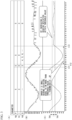
- FIG. 3 is a diagram showing a part of research results of the present inventors and the like.
- FIG. 3 is a diagram showing examples of a time waveform of the heading deviation calculated by the heading deviation calculation unit 14C of the heading control device 14 of the marine vessel 1 according to the first embodiment, a time waveform of the instruction value STR calculated by the PID control unit 14D, and the like.
- FIG. 3(A) shows the proportional gain Kp, the integral gain Ki, and the derivative gain Kd during the period indicated by the horizontal axis in FIG. 3 by "P,” “I,” and “D.”
- FIG. 3(B) shows the time waveform of the instruction value STR calculated by the PID control unit 14D.
- FIG. 3(C) shows the time waveform of the heading deviation calculated by the heading deviation calculation unit 14C.
- control by the heading control device 14 of the marine vessel 1 of the first embodiment is performed, and before the time 111, control similar to automatic steering by the above-described known automatic steering device is performed.
- the heading deviation (see FIG. 3(C) ) becomes larger than a threshold value TH1 (see FIG. 3(C) ) due to disturbances by waves, wind, tides, and the like, constant changes in strength of waves, wind, tides, and the like, etc.
- a state in which a target heading angle is larger than the actual heading angle by the threshold value TH1 or more for example, a state in which the actual heading is directed more leftward than the target heading
- a state in which the actual heading angle is larger than the target heading angle by the threshold value TH1 or more for example, a state in which the actual heading is directed more rightward than the target heading
- a product of the proportional gain Kp and the heading deviation is calculated as the instruction value, and thus the time waveform of the instruction value (see FIG. 3(B) ) also repeatedly increases and decreases in the same way as the time waveform of the heading deviation (see FIG. 3(C) ).
- control by the heading control device 14 of the marine vessel 1 of the first embodiment is performed.
- the heading deviation calculated by the heading deviation calculation unit 14C is less than the threshold value TH1, and thus the gain setting unit 14E maintains a value of the derivative gain Kd at "3" (see FIG. 3(A) ) without adding a derivative gain addition correction quantity (for example, "0.01") to the current value of the derivative gain Kd.
- a derivative gain addition correction quantity for example, "0.01"
- the heading deviation calculation unit 14C tends to transition from a state in which the target heading angle is greater than the actual heading angle by the threshold value TH1 or more (for example, a state in which the actual heading is directed more leftward than the target heading) to a state in which the actual heading angle is greater than the target heading angle by the threshold value TH1 or more (for example, a state in which the actual heading is directed rightward from the target heading).
- the heading deviation calculated by the heading deviation calculation unit 14C becomes equal to or greater than the threshold value TH1.
- the actual heading angle is in a state in which it is greater than the target heading angle by the threshold value TH1 or more (for example, a state in which the actual heading is directed more rightward than the target heading).
- the gain setting unit 14E performs a process of adding the derivative gain addition correction quantity to the current value of the derivative gain Kd at a predetermined time interval, for example.
- the value of the derivative gain Kd increases from "3" to "8.”
- the heading deviation calculated by the heading deviation calculation unit 14C can be made less than the threshold value TH1.
- the gain setting unit 14E maintains the value of the derivative gain Kd at "8" without adding the derivative gain addition correction quantity to the current value of the derivative gain Kd (see FIG. 3(A) ).
- the present inventors and the like have been able to confirm through their research that, as shown in FIG. 3 , the heading deviation (see FIG. 3(C) ) can be appropriately controlled by performing control by the heading control device 14 of the marine vessel 1 of the first embodiment.
- the present inventors and the like have found that, in the case in which the heading deviation (see FIG. 3(C) ) is equal to or greater than the threshold value TH1, the heading deviation can be inhibited below the threshold value TH1 by adding the derivative gain addition correction quantity to the current value of the derivative gain Kd (see FIG. 3(A) ).
- FIG. 4 is a diagram showing another part of the research results of the present inventors.
- FIG. 4 is a diagram showing other examples of the time waveform of the heading deviation calculated by the heading deviation calculation unit 14C of the heading control device 14 of the marine vessel 1 of the first embodiment, the time waveform of the instruction value STR calculated by the PID control unit 14D, and the like.
- FIG. 4(A) shows the proportional gain Kp, the integral gain Ki, and the derivative gain Kd during the period indicated by the horizontal axis in FIG. 4 by "P,” “I,” and “D.”
- FIG. 4(B) shows the time waveform of the instruction value STR calculated by the PID control unit 14D.
- FIG. 4(C) shows the time waveform of the heading deviation calculated by the heading deviation calculation unit 14C.
- the present inventors and the like have confirmed through their intensive research that the instruction value STR (see FIG. 4(B) ) calculated by the PID control unit 14D may change significantly due to influence of disturbances received by the marine vessel 1, as during the period from the time t21 to a time t22.
- the present inventors and the like have found through their intensive research that, by executing the process of subtracting the derivative gain reduction correction quantity (for example, "0.1") from the current value of the derivative gain Kd (see FIG. 4(A) ) as during the period from the time t21 to the time t22, it is possible to inhibit a large change in the instruction value STR (see FIG. 4(B) ) calculated by the PID control unit 14D.
- the derivative gain reduction correction quantity for example, "0.1"
- the gain setting unit 14E performs a process of subtracting the derivative gain reduction correction quantity from the current value of the derivative gain Kd.
- the evaluation value E t of the change quantity in the instruction value STR (see FIG. 4(B) ) calculated by the PID control unit 14D is equal to or greater than the threshold value TH2. For that reason, until the evaluation value E t of the change quantity in the instruction value STR (see FIG. 4(B) ) calculated by the PID control unit 14D becomes less than the threshold value TH2 (state at time t22), the gain setting unit 14E repeatedly performs the process of subtracting the derivative gain reduction correction quantity from the current value of the derivative gain Kd (see FIG. 4(A) ), thereby reducing the derivative gain Kd from the value greater than "16" to "8.”
- the present inventors and the like have confirmed through their research that, as shown in FIG. 4 , by performing the control by the heading control device 14 of the marine vessel 1 of the first embodiment, it is possible to inhibit a large change in the instruction value STR (see FIG. 4(B) ).
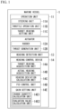
- FIG. 5 is a flowchart showing an example of processing executed in the marine vessel 1 of the first embodiment.
- the target heading setting unit 11C sets the target heading of the marine vessel 1 in step S11.
- step S12 the heading detection unit 13 detects the actual heading of the marine vessel 1 at the timing when the target heading is set in step S11.
- step S13 the target heading acquisition unit 14A acquires the actual heading detected in step S12 as the target heading of the marine vessel 1.
- step S14 the heading detection unit 13 detects the actual heading of the marine vessel 1.
- step S15 the actual heading acquisition unit 14B acquires the actual heading of the marine vessel 1 detected in step S14 as the actual heading of the marine vessel 1 used for the control by the heading control device 14.
- step S16 the heading deviation calculation unit 14C calculates the heading deviation, which is the difference between the target heading acquired in step S13 and the actual heading detected in step S14 (specifically, the actual heading acquired in step S15).
- step S17 the PID control unit 14D executes the PID control. Specifically, the PID control unit 14D calculates the instruction value STR for the actuator 12 from the heading deviation calculated in step S16.
- step S18 the gain setting unit 14E sets the proportional gain Kp, the integral gain Ki, and the derivative gain Kd used for the PID control on the basis of the heading deviation calculated in step S16 and the instruction value STR calculated in step S17.
- FIG. 6 is a flow chart showing an example of the processing executed in step S18 shown in FIG. 5 .
- step S18A the gain setting unit 14E determines whether or not the heading deviation calculated in step S16 is equal to or greater than the threshold value TH1. If the heading deviation is greater than or equal to the threshold value TH1, the process proceeds to step S18B, and if the heading deviation is less than the threshold value TH1, the process proceeds to step S18C.
- step S18B the gain setting unit 14E adds the derivative gain increase correction quantity to the current value of the derivative gain Kd, and the process proceeds to step S18C.
- step S18C the evaluation value calculation unit 14E2 calculates the evaluation value E t of the change quantity in the instruction value STR calculated in step S17. Also, in step S18C, the gain setting unit 14E determines whether or not the evaluation value E t of the change quantity of the instruction value STR is equal to or greater than the threshold value TH2. If the evaluation value E t of the change quantity in the instruction value STR is equal to or greater than the threshold value TH2, the process proceeds to step S18D, and if the evaluation value E t of the change quantity in the instruction value STR is less than the threshold value TH2, the process proceeds to step S18E.
- step S18D the gain setting unit 14E subtracts the derivative gain reduction correction quantity from the current value of the derivative gain Kd, and the process proceeds to step S18E.
- step S18E the gain setting unit 14E determines whether or not to end the routine shown in FIG. 6 . If NO, the process returns to step S18A, and if YES, the routine shown in FIG. 6 ends.
- the marine vessel 1 of the second embodiment is configured in the same manner as the marine vessel 1 of the first embodiment described above, except for the points described later. Accordingly, according to the marine vessel 1 of the second embodiment, the same effects as those of the marine vessel 1 of the first embodiment described above can be provided except for the points described later.
- the marine vessel 1 of the first embodiment is a marine vessel such as a PWC.
- the marine vessel 1 of the second embodiment is a marine vessel other than PWC.
- the marine vessel 1 of the second embodiment is a small marine vessel such as the small marine vessel described in Japanese Patent No. 3118475 , for example.
- the marine vessel 1 of the second embodiment is, for example, a marine vessel equipped with an outboard motor, such as a marine vessel equipped with an outboard motor described in Japanese Patent No. 6198192 , or Japanese Unexamined Patent Application, First Publication No. 2007-22284 , or the like.
- the marine vessel of the second embodiment is a marine vessel equipped with an inboard or outboard motor or an inboard engine.
- the marine vessel of the second embodiment is a large marine vessel equipped with a side thruster.
- each unit provided in the marine vessel 1 may be realized by recording a program for realizing these functions on a computer-readable recording medium and causing a computer system to read and execute the program recorded on this recording medium.
- computer system includes an OS and hardware such as peripheral devices.
- the term "computer-readable recording medium” indicates a storage unit including a portable medium such as a flexible disk, a magneto-optical disk, ROM, and CD-ROM, and a hard disk built into a computer system.
- the term “computer-readable recording medium” may also include a medium that dynamically retains a program for a short period of time such as a communication line for transmitting the program via a network such as the Internet or a communication line such as a telephone line, and in that case, a medium that holds the program for a certain period of time such as a volatile memory inside the computer system serving as a server and client.
- the program may be one for realizing some of the above-described functions, or may be one capable of realizing the above-described functions in combination with programs already recorded in the computer system.
Landscapes
- Engineering & Computer Science (AREA)
- Chemical & Material Sciences (AREA)
- Combustion & Propulsion (AREA)
- Mechanical Engineering (AREA)
- Ocean & Marine Engineering (AREA)
- Radar, Positioning & Navigation (AREA)
- Aviation & Aerospace Engineering (AREA)
- Remote Sensing (AREA)
- Physics & Mathematics (AREA)
- General Physics & Mathematics (AREA)
- Automation & Control Theory (AREA)
- Feedback Control In General (AREA)
- Control Of Position, Course, Altitude, Or Attitude Of Moving Bodies (AREA)
Applications Claiming Priority (2)
| Application Number | Priority Date | Filing Date | Title |
|---|---|---|---|
| JP2020200968A JP7531377B2 (ja) | 2020-12-03 | 2020-12-03 | 船舶、船首方位制御方法、船首方位制御装置およびプログラム |
| PCT/JP2021/044086 WO2022118881A1 (ja) | 2020-12-03 | 2021-12-01 | 船舶、船首方位制御方法、船首方位制御装置およびプログラム |
Publications (2)
| Publication Number | Publication Date |
|---|---|
| EP4239418A1 true EP4239418A1 (de) | 2023-09-06 |
| EP4239418A4 EP4239418A4 (de) | 2024-08-07 |
Family
ID=81853302
Family Applications (1)
| Application Number | Title | Priority Date | Filing Date |
|---|---|---|---|
| EP21900632.7A Withdrawn EP4239418A4 (de) | 2020-12-03 | 2021-12-01 | Wasserfahrzeug, kurssteuerungsverfahren, kurssteuerungsvorrichtung und programm |
Country Status (4)
| Country | Link |
|---|---|
| US (1) | US20230303233A1 (de) |
| EP (1) | EP4239418A4 (de) |
| JP (1) | JP7531377B2 (de) |
| WO (1) | WO2022118881A1 (de) |
Families Citing this family (2)
| Publication number | Priority date | Publication date | Assignee | Title |
|---|---|---|---|---|
| CN114859882A (zh) * | 2022-01-17 | 2022-08-05 | 上海欧迅睿智能科技有限公司 | 一种多推进器水面航行器的航向控制方法 |
| CN120972506B (zh) * | 2025-10-23 | 2025-12-26 | 济南大学 | 一种基于改进型pid控制的船舶航向保持优化方法 |
Family Cites Families (17)
| Publication number | Priority date | Publication date | Assignee | Title |
|---|---|---|---|---|
| US4074648A (en) | 1976-10-18 | 1978-02-21 | Sperry Rand Corporation | Adaptive autopilot for marine vessels |
| JP3118475B2 (ja) | 1991-09-13 | 2000-12-18 | 日本発条株式会社 | 駐艇装置 |
| JP3683890B2 (ja) * | 2003-03-31 | 2005-08-17 | 財団法人ファジィシステム研究所 | 船舶等の制御装置及び方法 |
| CN100494898C (zh) * | 2004-12-30 | 2009-06-03 | 中国科学院自动化研究所 | 一种航迹自动舵控制系统及其方法 |
| JP4781026B2 (ja) | 2005-07-15 | 2011-09-28 | ユニカス工業株式会社 | 2または3基掛けの船外機の操舵機構 |
| JP2008230484A (ja) | 2007-03-22 | 2008-10-02 | Yokogawa Denshikiki Co Ltd | 自動操舵装置および自動操舵方法 |
| JP5196649B2 (ja) | 2008-07-02 | 2013-05-15 | 日本発條株式会社 | 水上オートバイのステアリングハンドル装置 |
| JP5400506B2 (ja) | 2009-07-07 | 2014-01-29 | マロール株式会社 | 船舶の自動操舵装置および自動操舵プログラム |
| JP2011189884A (ja) | 2010-03-16 | 2011-09-29 | Furuno Electric Co Ltd | 自動操舵装置、自動操舵方法及び自動操舵プログラム |
| JP6198192B2 (ja) | 2014-03-04 | 2017-09-20 | 日本発條株式会社 | 操作レバーおよびリモートコントロール装置 |
| JP6632803B2 (ja) * | 2015-02-06 | 2020-01-22 | 古野電気株式会社 | 船体制御装置、船体制御方法 |
| US10671073B2 (en) | 2017-02-15 | 2020-06-02 | Brunswick Corporation | Station keeping system and method |
| WO2019213435A1 (en) | 2018-05-02 | 2019-11-07 | Autonomous Marine Systems, Inc. | Autonomous sailing vessel |
| CN109787673B (zh) * | 2019-01-25 | 2020-08-28 | 上海大学 | 一种无人艇用半潜式海洋动力定位通信中继系统 |
| JP2020200968A (ja) | 2019-06-06 | 2020-12-17 | シャープ株式会社 | 電気機器 |
| CN111367178B (zh) | 2019-12-26 | 2023-01-20 | 北京海兰信数据科技股份有限公司 | 一种船舶自动舵的自适应控制装置及方法 |
| CN111413981B (zh) * | 2020-04-07 | 2023-02-21 | 上海海事大学 | 一种船舶自动舵复合神经网络pid控制方法 |
-
2020
- 2020-12-03 JP JP2020200968A patent/JP7531377B2/ja active Active
-
2021
- 2021-12-01 EP EP21900632.7A patent/EP4239418A4/de not_active Withdrawn
- 2021-12-01 WO PCT/JP2021/044086 patent/WO2022118881A1/ja not_active Ceased
-
2023
- 2023-05-30 US US18/325,482 patent/US20230303233A1/en not_active Abandoned
Also Published As
| Publication number | Publication date |
|---|---|
| US20230303233A1 (en) | 2023-09-28 |
| JP7531377B2 (ja) | 2024-08-09 |
| EP4239418A4 (de) | 2024-08-07 |
| JP2022088863A (ja) | 2022-06-15 |
| WO2022118881A1 (ja) | 2022-06-09 |
Similar Documents
| Publication | Publication Date | Title |
|---|---|---|
| US20230303233A1 (en) | Marine vessel, heading control method, heading control device, and program | |
| US10000270B2 (en) | Moving body control device, moving body control method, and moving body control program | |
| CN112334852A (zh) | 用于航海船舶自主进坞的方法、设备和装置 | |
| JP5442071B2 (ja) | 操船制御装置、自動操船制御システム、操船制御方法、及びプログラム | |
| US20120130570A1 (en) | System and method for a marine vessel autopilot | |
| JP2014004911A (ja) | 非線形の自己回帰モデルによる船舶の航路保持方法 | |
| Cruz et al. | Auto-heading controller for an autonomous sailboat | |
| Kim et al. | A numerical and experimental study on the obstacle collision avoidance system using a 2D LiDAR sensor for an autonomous surface vehicle | |
| Holvik | Basics of dynamic positioning | |
| US11947021B2 (en) | Method for determining the position and orientation of a vehicle | |
| JP4706032B2 (ja) | 自動船位保持制御方法及び自動船位保持制御装置 | |
| EP3798111A1 (de) | Schiffsgeschwindigkeitsregelvorrichtung, schiffsgeschwindigkeitsregelverfahren und schiffsgeschwindigkeitsregelprogramm | |
| EP4417937A1 (de) | Informationsverarbeitungsvorrichtung, steuerungsverfahren, programm und speichermedium | |
| EP3423910B1 (de) | Schiffsdriftsteuerungssystem | |
| KR101380462B1 (ko) | 선박운항정보 추정 기반 타선인식 지원 시스템 및 방법 | |
| EP4410663A1 (de) | Schiff, schiffssteuerungsvorrichtung, schiffssteuerungsverfahren und programm | |
| Okazaki et al. | A Study on Ship Berthing Support System | |
| US20230211859A1 (en) | Automatic ship handling system, ship control device, ship control method, and program | |
| JP2009132257A (ja) | 操船制御方法、プログラム及び装置、並びに自動操船制御システム | |
| KR100465105B1 (ko) | 선박의 편류각을 고려한 자동항로 추적장치 및 그추적방법 | |
| JP5566426B2 (ja) | 操船制御装置、自動操船制御システム、操船制御方法、及びプログラム | |
| Kupraty et al. | Global and local planning of ship route using MATLAB and Simulink | |
| KR20210096566A (ko) | 키 제어 장치 및 선박 | |
| JP2018131028A (ja) | 位置保持方法および移動体 | |
| KR20210084962A (ko) | 복수의 pid 제어를 이용한 선박의 자동 조타 방법 |
Legal Events
| Date | Code | Title | Description |
|---|---|---|---|
| STAA | Information on the status of an ep patent application or granted ep patent |
Free format text: STATUS: THE INTERNATIONAL PUBLICATION HAS BEEN MADE |
|
| PUAI | Public reference made under article 153(3) epc to a published international application that has entered the european phase |
Free format text: ORIGINAL CODE: 0009012 |
|
| STAA | Information on the status of an ep patent application or granted ep patent |
Free format text: STATUS: REQUEST FOR EXAMINATION WAS MADE |
|
| 17P | Request for examination filed |
Effective date: 20230531 |
|
| AK | Designated contracting states |
Kind code of ref document: A1 Designated state(s): AL AT BE BG CH CY CZ DE DK EE ES FI FR GB GR HR HU IE IS IT LI LT LU LV MC MK MT NL NO PL PT RO RS SE SI SK SM TR |
|
| DAV | Request for validation of the european patent (deleted) | ||
| DAX | Request for extension of the european patent (deleted) | ||
| REG | Reference to a national code |
Ref country code: DE Ref legal event code: R079 Free format text: PREVIOUS MAIN CLASS: G05B0011360000 Ipc: G05D0001646000 |
|
| RIC1 | Information provided on ipc code assigned before grant |
Ipc: G05D 109/30 20240101ALN20240415BHEP Ipc: G05D 107/00 20240101ALN20240415BHEP Ipc: G05D 105/22 20240101ALN20240415BHEP Ipc: G05D 1/43 20240101ALI20240415BHEP Ipc: B63H 25/30 20060101ALI20240415BHEP Ipc: B63H 25/04 20060101ALI20240415BHEP Ipc: B63B 79/40 20200101ALI20240415BHEP Ipc: G05B 13/02 20060101ALI20240415BHEP Ipc: G05B 11/36 20060101ALI20240415BHEP Ipc: G05D 1/646 20240101AFI20240415BHEP |
|
| A4 | Supplementary search report drawn up and despatched |
Effective date: 20240710 |
|
| RIC1 | Information provided on ipc code assigned before grant |
Ipc: G05D 109/30 20240101ALN20240704BHEP Ipc: G05D 107/00 20240101ALN20240704BHEP Ipc: G05D 105/22 20240101ALN20240704BHEP Ipc: G05D 1/43 20240101ALI20240704BHEP Ipc: B63H 25/30 20060101ALI20240704BHEP Ipc: B63H 25/04 20060101ALI20240704BHEP Ipc: B63B 79/40 20200101ALI20240704BHEP Ipc: G05B 13/02 20060101ALI20240704BHEP Ipc: G05B 11/36 20060101ALI20240704BHEP Ipc: G05D 1/646 20240101AFI20240704BHEP |
|
| STAA | Information on the status of an ep patent application or granted ep patent |
Free format text: STATUS: THE APPLICATION IS DEEMED TO BE WITHDRAWN |
|
| 18D | Application deemed to be withdrawn |
Effective date: 20250131 |