EP4239210B1 - Reverse-input-blocking clutch - Google Patents
Reverse-input-blocking clutch Download PDFInfo
- Publication number
- EP4239210B1 EP4239210B1 EP22892626.7A EP22892626A EP4239210B1 EP 4239210 B1 EP4239210 B1 EP 4239210B1 EP 22892626 A EP22892626 A EP 22892626A EP 4239210 B1 EP4239210 B1 EP 4239210B1
- Authority
- EP
- European Patent Office
- Prior art keywords
- input
- output
- side engaging
- pair
- engaging portion
- Prior art date
- Legal status (The legal status is an assumption and is not a legal conclusion. Google has not performed a legal analysis and makes no representation as to the accuracy of the status listed.)
- Active
Links
Images


Classifications
-
- F—MECHANICAL ENGINEERING; LIGHTING; HEATING; WEAPONS; BLASTING
- F16—ENGINEERING ELEMENTS AND UNITS; GENERAL MEASURES FOR PRODUCING AND MAINTAINING EFFECTIVE FUNCTIONING OF MACHINES OR INSTALLATIONS; THERMAL INSULATION IN GENERAL
- F16D—COUPLINGS FOR TRANSMITTING ROTATION; CLUTCHES; BRAKES
- F16D41/00—Freewheels or freewheel clutches
- F16D41/06—Freewheels or freewheel clutches with intermediate wedging coupling members between an inner and an outer surface
- F16D41/08—Freewheels or freewheel clutches with intermediate wedging coupling members between an inner and an outer surface with provision for altering the freewheeling action
- F16D41/082—Freewheels or freewheel clutches with intermediate wedging coupling members between an inner and an outer surface with provision for altering the freewheeling action the intermediate coupling members wedging by movement other than pivoting or rolling
-
- F—MECHANICAL ENGINEERING; LIGHTING; HEATING; WEAPONS; BLASTING
- F16—ENGINEERING ELEMENTS AND UNITS; GENERAL MEASURES FOR PRODUCING AND MAINTAINING EFFECTIVE FUNCTIONING OF MACHINES OR INSTALLATIONS; THERMAL INSULATION IN GENERAL
- F16D—COUPLINGS FOR TRANSMITTING ROTATION; CLUTCHES; BRAKES
- F16D3/00—Yielding couplings, i.e. with means permitting movement between the connected parts during the drive
- F16D3/50—Yielding couplings, i.e. with means permitting movement between the connected parts during the drive with the coupling parts connected by one or more intermediate members
-
- F—MECHANICAL ENGINEERING; LIGHTING; HEATING; WEAPONS; BLASTING
- F16—ENGINEERING ELEMENTS AND UNITS; GENERAL MEASURES FOR PRODUCING AND MAINTAINING EFFECTIVE FUNCTIONING OF MACHINES OR INSTALLATIONS; THERMAL INSULATION IN GENERAL
- F16D—COUPLINGS FOR TRANSMITTING ROTATION; CLUTCHES; BRAKES
- F16D41/00—Freewheels or freewheel clutches
- F16D41/06—Freewheels or freewheel clutches with intermediate wedging coupling members between an inner and an outer surface
- F16D41/08—Freewheels or freewheel clutches with intermediate wedging coupling members between an inner and an outer surface with provision for altering the freewheeling action
- F16D41/10—Freewheels or freewheel clutches with intermediate wedging coupling members between an inner and an outer surface with provision for altering the freewheeling action with self-actuated reversing
-
- F—MECHANICAL ENGINEERING; LIGHTING; HEATING; WEAPONS; BLASTING
- F16—ENGINEERING ELEMENTS AND UNITS; GENERAL MEASURES FOR PRODUCING AND MAINTAINING EFFECTIVE FUNCTIONING OF MACHINES OR INSTALLATIONS; THERMAL INSULATION IN GENERAL
- F16D—COUPLINGS FOR TRANSMITTING ROTATION; CLUTCHES; BRAKES
- F16D43/00—Automatic clutches
- F16D43/02—Automatic clutches actuated entirely mechanically
- F16D43/04—Automatic clutches actuated entirely mechanically controlled by angular speed
- F16D43/14—Automatic clutches actuated entirely mechanically controlled by angular speed with centrifugal masses actuating the clutching members directly in a direction which has at least a radial component; with centrifugal masses themselves being the clutching members
- F16D43/18—Automatic clutches actuated entirely mechanically controlled by angular speed with centrifugal masses actuating the clutching members directly in a direction which has at least a radial component; with centrifugal masses themselves being the clutching members with friction clutching members
-
- F—MECHANICAL ENGINEERING; LIGHTING; HEATING; WEAPONS; BLASTING
- F16—ENGINEERING ELEMENTS AND UNITS; GENERAL MEASURES FOR PRODUCING AND MAINTAINING EFFECTIVE FUNCTIONING OF MACHINES OR INSTALLATIONS; THERMAL INSULATION IN GENERAL
- F16D—COUPLINGS FOR TRANSMITTING ROTATION; CLUTCHES; BRAKES
- F16D43/00—Automatic clutches
- F16D43/02—Automatic clutches actuated entirely mechanically
- F16D43/20—Automatic clutches actuated entirely mechanically controlled by torque, e.g. overload-release clutches, slip-clutches with means by which torque varies the clutching pressure
- F16D43/21—Automatic clutches actuated entirely mechanically controlled by torque, e.g. overload-release clutches, slip-clutches with means by which torque varies the clutching pressure with friction members
- F16D43/211—Automatic clutches actuated entirely mechanically controlled by torque, e.g. overload-release clutches, slip-clutches with means by which torque varies the clutching pressure with friction members with radially applied torque-limiting friction surfaces
-
- F—MECHANICAL ENGINEERING; LIGHTING; HEATING; WEAPONS; BLASTING
- F16—ENGINEERING ELEMENTS AND UNITS; GENERAL MEASURES FOR PRODUCING AND MAINTAINING EFFECTIVE FUNCTIONING OF MACHINES OR INSTALLATIONS; THERMAL INSULATION IN GENERAL
- F16D—COUPLINGS FOR TRANSMITTING ROTATION; CLUTCHES; BRAKES
- F16D51/00—Brakes with outwardly-movable braking members co-operating with the inner surface of a drum or the like
- F16D51/10—Brakes with outwardly-movable braking members co-operating with the inner surface of a drum or the like shaped as exclusively radially-movable brake-shoes
- F16D51/12—Brakes with outwardly-movable braking members co-operating with the inner surface of a drum or the like shaped as exclusively radially-movable brake-shoes mechanically actuated
-
- F—MECHANICAL ENGINEERING; LIGHTING; HEATING; WEAPONS; BLASTING
- F16—ENGINEERING ELEMENTS AND UNITS; GENERAL MEASURES FOR PRODUCING AND MAINTAINING EFFECTIVE FUNCTIONING OF MACHINES OR INSTALLATIONS; THERMAL INSULATION IN GENERAL
- F16D—COUPLINGS FOR TRANSMITTING ROTATION; CLUTCHES; BRAKES
- F16D59/00—Self-acting brakes, e.g. coming into operation at a predetermined speed
-
- F—MECHANICAL ENGINEERING; LIGHTING; HEATING; WEAPONS; BLASTING
- F16—ENGINEERING ELEMENTS AND UNITS; GENERAL MEASURES FOR PRODUCING AND MAINTAINING EFFECTIVE FUNCTIONING OF MACHINES OR INSTALLATIONS; THERMAL INSULATION IN GENERAL
- F16D—COUPLINGS FOR TRANSMITTING ROTATION; CLUTCHES; BRAKES
- F16D67/00—Combinations of couplings and brakes; Combinations of clutches and brakes
-
- F—MECHANICAL ENGINEERING; LIGHTING; HEATING; WEAPONS; BLASTING
- F16—ENGINEERING ELEMENTS AND UNITS; GENERAL MEASURES FOR PRODUCING AND MAINTAINING EFFECTIVE FUNCTIONING OF MACHINES OR INSTALLATIONS; THERMAL INSULATION IN GENERAL
- F16D—COUPLINGS FOR TRANSMITTING ROTATION; CLUTCHES; BRAKES
- F16D3/00—Yielding couplings, i.e. with means permitting movement between the connected parts during the drive
- F16D3/02—Yielding couplings, i.e. with means permitting movement between the connected parts during the drive adapted to specific functions
- F16D3/04—Yielding couplings, i.e. with means permitting movement between the connected parts during the drive adapted to specific functions specially adapted to allow radial displacement, e.g. Oldham couplings
Definitions
- the present invention relates to a reverse input blocking clutch which transmits a rotational torque input from an input member to an output member and completely blocks a rotational torque reversely input to the output member so that the rotational torque is not transmitted to the input member or only part of the rotational torque is transmitted to the input member while the rest is blocked.
- a reverse input blocking clutch includes an input member that is connected to a drive source input mechanism or the like and an output member that is connected to a decelerating mechanism or the like and has a function of transmitting a rotational torque input from the input member to the output member and completely blocking a rotational torque reversely input to the output member such that the rotational torque is not transmitted to the input member or only a part of the rotational torque is transmitted to the input member while the rest is blocked.
- the reverse input blocking clutch is roughly classified into a locking type and a free type depending on the difference in a mechanism that blocks a rotational torque reversely input to the output member.
- the lock type reverse input blocking clutch includes a mechanism that prevents the rotation of the output member when a rotational torque is reversely input to the output member.
- the free type reverse input blocking clutch includes a mechanism that revolves the output member when a rotational torque is input to the output member. The use of any one of the lock type reverse input blocking clutch and the free type reverse input blocking clutch is appropriately determined depending on the application of the device incorporating the reverse input blocking clutch.
- the pamphlet of WO 2021/054481 describes the lock type reverse input blocking clutch.
- the reverse input blocking clutch described in the pamphlet of WO 2021/054481 includes an input member having a pair of input side engaging portions, an output member having an output side engaging portion, a pressed member having a pressed surface, and an engagement element having an engagement element body and a link member.
- the engagement element body includes an output side engaged portion which engages with the output side engaging portion and a swing support portion which is located on the side closer to the pressed surface than the input side engaging portion.
- the link member includes a first end portion which is connected to the swing support portion in a swingable manner and a second end portion which is connected to the input side engaging portion in a swingable manner.
- the engagement element is configured to be displaced in a direction moving away from the pressed surface so that the output side engaged portion engages with the output side engaging portion to transmit the rotational torque input to the input member to the output member in such a manner that the input side engaging portion pulls the swing support portion through the link member when the rotational torque is input to the input member and is configured to press the pressing surface against the pressed surface so that the pressing surface frictionally engages with the pressed surface based on that the output side engaging portion engages with the output side engaged portion when the rotational torque is reversely input to the output member.
- the state (locked or semi-locked state) in which the pressing surface is pressed against the pressed surface can be smoothly switched to the state (unlocked or semi-unlocked state) in which the pressing surface is separated from the pressed surface when the rotational torque is input to the input member.
- the present invention has been made in view of the above-described circumstances and an object thereof is to realize a structure of a reverse input blocking clutch capable of smoothly switching a state (locked or semi-locked state) in which a pressing surface is pressed against a pressed surface to a state (unlocked or semi-unlocked state) in which the pressing surface is separated from the pressed surface when a rotational torque is input to the input member and reducing manufacturing cost.
- a reverse input blocking clutch includes a pressed member, an input member, an output member, and an engagement element.
- the pressed member includes a pressed surface provided on an inner peripheral surface.
- the input member includes at least one input side engaging portion disposed on a radial inside of the pressed surface and is disposed coaxially with the pressed surface.
- the output member includes an output side engaging portion disposed on the radial inside in relation to the input side engaging portion on the radial inside of the pressed surface and is disposed coaxially with the pressed surface.
- the engagement element includes a pair of pressing surfaces each facing the pressed surface and circumferentially separated from each other, an input side engaged portion engageable with the input side engaging portion, and an output side engaged portion engageable with the output side engaging portion and is disposed to be movable in a first direction as a far and near direction with respect to the pressed surface.
- Each pressing surface is formed by a partially cylindrical convex curved surface having a curvature radius smaller than the curvature radius of the pressed surface.
- the engagement element is configured to be displaced in a direction moving away from the pressed surface in the first direction based on that the input side engaging portion engages with the input side engaged portion when the rotational torque is input to the input member and is configured to transmit a rotational torque input to the input member to the output member based on that the output side engaged portion engages with the output side engaging portion and the engagement element is configured to press the pressing surface against the pressed surface so that the pressing surface frictionally engages with the pressed surface based on that the output side engaging portion engages with the output side engaged portion when a rotational torque is reversely input to the output member.
- a distance between a rotation center of the input member and a contact portion between the input side engaging portion and the input side engaged portion in a second direction orthogonal to both the first direction and the rotation center of the input member is shorter than the distance between a rotation center of the output member and a contact portion between the output side engaging portion and the output side engaged portion in the second direction.
- the contact portion between the output side engaging portion and the output side engaged portion is located on the side closer to the rotation center of the output member in the first direction in relation to a virtual line connecting a contact portion between one pressing surface of the pair of pressing surfaces and the pressed surface and the rotation center of the output member.
- the reverse input blocking clutch can include a pair of the engagement elements and the input member can include a pair of the input side engaging portions.
- the reverse input blocking clutch of an aspect of the present invention it is possible to smoothly switch a state (locked or semi-locked state) in which a pressing surface is pressed against a pressed surface to a state (unlocked or semi-unlocked state) in which the pressing surface is separated from the pressed surface when a rotational torque is input to an input member and to reduce a manufacturing cost.
- an axial direction, a radial direction, and a circumferential direction refer to an axial direction, a radial direction, and a circumferential direction of a reverse input blocking clutch 1 unless otherwise specified.
- the axial direction, the radial direction, and the circumferential direction of the reverse input blocking clutch 1 coincide with an axial direction, a radial direction, and a circumferential direction of an input member 3 and an axial direction, a radial direction, and a circumferential direction of an output member 4.
- One axial side refers to the side of the input member 3 (the right side of FIG. 2 ) and the other axial side refers to the side of the output member 4 (the left side of FIG. 2 ).
- the reverse input blocking clutch 1 of this example includes a pressed member 2, the input member 3, the output member 4, and a pair of engagement elements 5.
- the reverse input blocking clutch 1 has a reverse input blocking function of transmitting a rotational torque input to the input member 3 to the output member 4 and completely blocking a rotational torque reversely input to the output member 4 such that the rotational torque is not transmitted to the input member 3 or only part of the rotational torque is transmitted to the input member 3 while the rest is blocked.
- a case in which the rotation direction of the input member 3 is the counterclockwise direction and the rotation direction of the output member 4 is the clockwise direction will be mainly described, but the present invention is not limited thereto. That is, the reverse input blocking clutch 1 of this example can block (lock) and unlock the reverse input rotational torque regardless of the rotation direction (torque input direction).
- the pressed member 2 has a cylindrical shape and is fixed to, for example, the other member (not shown) such as a housing or is integrally provided with the other member to restrict its rotation.
- the pressed member 2 includes a pressed surface 6 which is a cylindrical concave surface on the inner peripheral surface.
- the input member 3 is connected to an input side mechanism such as an electric motor and a rotational torque is input thereto.
- the input member 3 includes a substrate portion 7, an input shaft portion 8, and a pair of input side engaging portions 9.
- the substrate portion 7 has a substantially circular end surface shape when viewed from the axial direction.
- the input shaft portion 8 protrudes from the center portion of one axial side surface of the substrate portion 7 toward one axial side.
- the input shaft portion 8 includes an input side connection portion 10a provided at one axial portion to transmit a torque to the output portion of the input side mechanism.
- the input side connection portion 10a has a double sided shape including a pair of flat surfaces parallel to each other on the outer peripheral surface.
- the input side connection portion 10a can have any shape if the input side connection portion can be connected to the output portion of the input side mechanism to transmit a torque.
- the pair of input side engaging portions 9 has a substantially fan-shaped or substantially trapezoidal end surface shapes when viewed from the axial direction and protrudes from two positions on the other axial side of the substrate portion 7 on the opposite radial side to the other axial side.
- the pair of input side engaging portions 9 is separated from each other in the radial direction of the input member 3. Therefore, each of the input side engaging portions 9 is disposed on a portion on the other axial side of the substrate portion 7 that is radially outwardly deviated from the rotation center O.
- Each input side engaging portion 9 has a symmetrical shape with respect to the circumferential direction.
- radial inner side surfaces 9a of the input side engaging portions 9 are formed by flat surfaces parallel to each other and radial outer side surfaces 9b of the input side engaging portions 9 have the same cylindrical contour shape as the outer peripheral surface of the substrate portion 7.
- a pair of circumferential side surfaces 9c of the input side engaging portions 9 is formed by flat surfaces which are inclined in a direction moving away from each other as it goes outward in the radial direction.
- the output member 4 is connected to an output side mechanism such a deceleration mechanism and outputs a rotational torque.
- the output member 4 is disposed coaxially with the input member 3.
- the output member 4 includes an output shaft portion 11 and an output side engaging portion 12.
- the output shaft portion 11 includes a flange portion 18 provided at one axial portion to protrude outward in the radial direction and includes an output side connection portion 10b provided at the other axial portion to transmit a torque to the input portion of the output side mechanism.
- the output side connection portion 10b has a double sided shape including a pair of flat surfaces parallel to each other on the outer peripheral surface.
- the output side connection portion 10b can have any shape if the output side connection portion can be connected to the input portion of the output side mechanism to transmit a torque.
- the output side engaging portion 12 has a cam function. That is, the distance from the rotation center O of the output member 4 to the outer peripheral surface of the output side engaging portion 12 is not constant in the circumferential direction.
- the output side engaging portion 12 has a substantially rectangular or substantially elliptical end surface shape when viewed from the axial direction and protrudes from the center portion of one axial end surface of the output shaft portion 11 toward one axial side. That is, the outer peripheral surface of the output side engaging portion 12 is formed by a pair of flat surfaces 12a parallel to each other and a pair of convex curved surfaces 12b each having a partially cylindrical surface shape.
- the distance from the rotation center O of the output member 4 to the outer peripheral surface of the output side engaging portion 12 is not constant in the circumferential direction.
- the pair of convex curved surfaces 12b is formed by partial cylindrical surfaces centered on the rotation center O of the output member 4.
- the output side engaging portion 12 is symmetrical with respect to a virtual plane passing through the rotation center O of the output member 4 and orthogonal to the pair of flat surfaces 12a and is symmetrical with respect to a virtual plane passing through the rotation center O of the output member 4 and parallel to the pair of flat surfaces 12a.
- Such an output side engaging portion 12 is disposed between the pair of input side engaging portions 9.
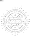
- the pair of engagement elements 5 has a substantially semicircular end surface shape when viewed from the axial direction and has a symmetrical shape with respect to the width direction (a direction parallel to a flat surface portion 15 and a direction indicated by an arrow B in FIG. 3 ).
- the pair of engagement elements 5 includes a pair of pressing surfaces 13 provided on the radial outer side surface so that each of them to faces the pressed surface 6 and they are separated from each other in the circumferential direction.
- Each pressing surface 13 is formed by a partially cylindrical convex curved surface having a curvature radius smaller than the curvature radius of the pressed surface 6.
- the portions circumferentially deviated from the pair of pressing surfaces 13 in the radial outer side surfaces of the pair of engagement elements 5 exist on the radial inside in relation to the virtual circle centered on the center axis O of the input member 3 and contacting the pair of pressing surfaces 13 when viewed from the axial direction. That is, the portions circumferentially deviated from the pair of pressing surfaces 13 in the radial outer side surfaces of the pair of engagement elements 5 do not contact the pressed surface 6 while the pair of pressing surfaces 13 contacts the pressed surface 6.
- each pressing surface 13 have surface properties with a larger friction coefficient with respect to the pressed surface 6 than other portions of the engagement element 5.
- Each pressing surface 13 can be integrally formed with the other portion of the engagement element 5 and can be formed on the surface of the friction material fixed to the other portion of the engagement element 5 by sticking, bonding, or the like.
- the pair of engagement elements 5 includes an output side engaged portion 14 which is provided at the center portion of the radial inner side surface in the width direction to engage with the output side engaging portion 12.
- the flat surface portion 15 is provided on the radial inner side surfaces of the pair of engagement elements 5 and a pair of convex portions 16 protruding toward the radial inside is provided at two positions of the flat surface portion 15 in the width direction.
- the output side engaged portion 14 is formed by a portion existing between the pair of convex portions 16 in the width direction in the flat surface portion 15.
- the width-direction dimension (the gap between the pair of convex portions 16) of the output side engaged portion 14 is set to be larger than the width-direction dimension of the flat surface 12a of the output side engaging portion 12.
- the radial direction with respect to the engagement element 5 refers to a direction perpendicular to the flat surface portion 15 indicated by the arrow A in FIG. 3 and the width direction with respect to the engagement element 5 refers to a direction parallel to the flat surface portion 15 indicated by the arrow B in FIG. 3 .
- the radial direction with respect to the engagement element 5 corresponds to a first direction which is a far and near direction with respect to the pressed surface 6 of the pair of pressing surfaces 13 of the engagement element 5 and the width direction with respect to the engagement element 5 corresponds to a second direction orthogonal to both the first direction and the rotation center O of the input member 3.
- the pair of engagement elements 5 includes an input side engaged portion 17 which is provided at the radial intermediate portion of the widthwise center portion to engage with the input side engaging portion 9.
- the input side engaged portion 17 is formed by a through hole which has a substantially arcuate opening shape when viewed from the axial direction and penetrates the radial intermediate portion at the widthwise center position of the engagement element 5 in the axial direction.
- the input side engaged portion 17 has a size that allows the input side engaging portion 9 to be loosely inserted.
- a gap exists in each of the width direction and the radial direction of the engagement element 5 between the input side engaging portion 9 and the inner surface of the input side engaged portion 17 while the input side engaging portion 9 is inserted into the input side engaged portion 17.
- the input side engaging portion 9 can be displaced in the rotation direction of the input member 3 with respect to the input side engaged portion 17 (the engagement element 5) and the input side engaged portion 17 can be displaced in the radial direction of the engagement element 5 with respect to the input side engaging portion 9.
- the input side engaged portion 17 includes a flat surface 17a which is provided on the radial inner side surface (the surface facing the outside in the radial direction) to be parallel to the flat surface portion 15.
- the input side engaged portion can also be formed by a bottomed hole that opens only to one axial side of the engagement element.
- the input side engaged portion can be formed by a notch opening to the radial outer side surface of the engagement element.
- the pair of engagement elements 5 is disposed on the radial inside of the pressed member 2 to be movable in the radial direction (first direction) of the pair of engagement elements 5 while the pair of pressing surfaces 13 of the engagement elements 5 faces the opposite sides in the radial direction and the radial inner side surfaces (flat surface portions 15) of the engagement elements 5 face each other.
- the pair of input side engaging portions 9 of the input member 3 disposed on one axial side is axially inserted into the input side engaged portions 17 of the pair of engagement elements 5 and the output side engaging portion 12 of the output member 4 disposed on the other axial side is axially inserted between the pair of output side engaged portions 14. That is, the pair of engagement elements 5 is disposed to sandwich the output side engaging portion 12 from the radial outside by their output side engaged portions 14.
- the inner diameter dimension of the pressed member 2 and the radial dimension of the engagement element 5 are regulated so that a gap exists in at least one of the portion between the pressed surface 6 and the pair of pressing surfaces 13 and the portion between the tip surfaces of the convex portions 16 while the pair of engagement elements 5 is disposed on the radial inside of the pressed member 2.
- FIGS. 4 and 5 exaggerately show the radial gap of the input member 3, the output member 4, and the pair of engagement elements 5.
- the input side engaging portion 9 rotates inside the input side engaged portion 17 in the rotation direction of the input member 3 (in the example of FIG. 4 , the counterclockwise direction) as shown in FIG. 4 . Then, the radial inner side surface 9a of the input side engaging portion 9 presses the flat surface 17a of the input side engaged portion 17 toward the radial inside so that each of the pair of engagement elements 5 moves in a direction moving away from the pressed surface 6. That is, each of the pair of engagement elements 5 is moved toward the radial inside which is a direction moving close to each other (the engagement element 5 located at the upper side of FIG. 4 is moved downward and the engagement element 5 located at the lower side of FIG.
- the radial inner side surfaces of the pair of engagement elements 5 move in a direction moving close to each other and the pair of output side engaged portions 14 sandwich the output side engaging portion 12 of the output member 4 from both radial sides. That is, the output side engaging portion 12 and the pair of output side engaged portions 14 are engaged (contacted) without rattling while the output member 4 is rotated so that the flat surface 12a of the output side engaging portion 12 is parallel to the flat surface portion 15 of the engagement element 5.
- the rotational torque input to the input member 3 is transmitted to the output member 4 through the pair of engagement elements 5 and is output from the output member 4.
- the reverse input blocking clutch 1 of this example moves each of the pair of engagement elements 5 in a direction moving away from the pressed surface 6 regardless of the rotation direction of the input member 3 when the rotational torque is input to the input member 3. Then, the rotational torque input to the input member 3 is transmitted to the output member 4 through the pair of engagement elements 5.
- the rotational torque reversely input to the output member 4 is completely blocked and is not transmitted to the input member 3 or only part of the rotational torque reversely input to the output member 4 is transmitted to the input member 3 while the rest is blocked.
- the pair of engagement elements 5 is stretched between the output side engaging portion 12 and the pressed member 2 to lock the output member 4 such that the pair of pressing surfaces 13 does not slide (relatively rotate) with respect to the pressed surface 6.
- the pair of engagement elements 5 is stretched between the output side engaging portion 12 and the pressed member 2 to semi-lock the output member 4 such that the pair of pressing surfaces 13 slides with respect to the pressed surface 6.
- the size of the gap between each component is adjusted so that the above operations are possible.
- a gap exists between the radial inner side surface 9a of the input side engaging portion 9 and the inner surface of the input side engaged portion 17 so that the pair of pressing surfaces 13 is further pressed toward the pressed surface 6 based on that the corner portion of the output side engaging portion 12 presses the output side engaged portion 14.
- each portion of the pressed member 2, the input member 3, the output member 4, and the pair of engagement elements 5 are regulated to satisfy the following relationship.
- a first distance D 1 which is a distance of a contact portion P in between the input side engaging portion 9 and the input side engaged portion 17 and the rotation center O of the input member 3 in the second direction is set to be shorter than a second distance D 2 of a contact portion P out between the output side engaging portion 12 and the output side engaged portion 14 and the rotation center O of the output member 4 (D 1 ⁇ D 2 ).
- a contact portion C 1 between the output side engaging portion 12 and the output side engaged portion 14 is located on the side close to the rotation center O of the output member 4 (the lower side of FIG. 5 ) in the first direction in relation to a virtual line L connecting the rotation center O of the output member 4 and a contact portion C 2 between the pressed surface 6 and the pressing surface 13 of one of the pair of pressing surfaces 13 (the pressing surface on the side closer to the contact portion C 1 than the rotation center O of the output member 4 in the second direction).
- the axial dimension can be shortened and the number of parts can be reduced.
- the reverse input blocking clutch 1 of this example converts the rotation of each of the input member 3 and the output member 4 into the radial movement of the engagement element 5. Then, the engagement element 5 is engaged with the output member 4 located on the radial inside of the engagement element 5 or the engagement element 5 is pressed against the pressed member 2 located on the radial outside of the engagement element 5 such that the rotation of the input member 3 and the output member 4 is converted into the radial movement of the engagement element 5 in this way.
- the reverse input blocking clutch 1 of this example can switch the unlocked or semi-unlocked state of the output member 4 that allows the transmission of the rotational torque from the input member 3 to the output member 4 and the locked or semi-locked state of the output member 4 that prevents or suppresses the rotation of the output member 4 based on the radial movement of the engagement element 5 controlled by the rotation of each of the input member 3 and the output member 4, the axial dimension of the reverse input blocking clutch 1 as a whole can be shortened.
- the engagement element 5 has both a function of transmitting the rotational torque input to the input member 3 to the output member 4 and a function of locking or semi-locking the output member 4. Therefore, the number of parts of the reverse input blocking clutch 1 can be reduced and the operation can be stabilized compared to a case in which the rotational torque transmitting function and the locking or semi-locking function are respectively provided in different members. For example, when the rotational torque transmitting function and the locking or semi-locking function are provided in different members, there is a possibility that the unlocking or semi-unlocking timing and the rotational torque transmission start timing do not match.
- the movement direction of the engagement element 5 can be controlled by regulating the magnitude relationship of both forces. Therefore, it is possible to stably and reliably perform the switching operation of the locked or semi-locked state and the unlocked or semi-unlocked state of the output member 4.
- the first distance D 1 is shorter than the second distance D 2 and the contact portion C 1 is located on the side closer to the rotation center O of the output member 4 in the first direction than the virtual line L in the locked or semi-locked state. Therefore, the locked or semi-locked state can be smoothly switched to the unlocked or semi-unlocked state. This reason will be described with reference to FIGS. 6A to 6C .
- the engagement element 5 tends to rotate around the contact portion C 1 in the clockwise direction when the rotational torque is input to the input member 3 in the counterclockwise direction as shown in FIG. 6A .
- the locus r 1 and the locus r 2 are indicated by the dashed lines in FIG. 6A , none of the pair of pressing surfaces 13 is pressed against the pressed surface 6.
- the reverse input blocking clutch 1 of this example a structure capable of smoothly switching the locked or semi-locked state to the unlocked or semi-unlocked state can be realized without configuring the engagement element to include the engagement element body and the link member as in the reverse input blocking clutch described in the pamphlet of WO 2021/054481 . Therefore, the number of parts can be reduced and the manufacturing cost can be reduced. Additionally, in FIGS. 6A to 6C , the contact portion P in and the contact portion C 2 are located at the same height in the first direction, but it is possible to obtain the same effects as those described above even when the positions of the contact portion P in and the contact portion C 2 in the first direction are different.
- FIG. 7 is a schematic view illustrating the effect of the reverse input blocking clutch according to an example of the embodiment.
- FIG. 7 shows an example of a case in which the input member 3 rotates in a direction opposite to the example shown in FIGS. 6A to 6C (that is, the clockwise direction).
- the occurrence of the biting is suppressed and the unlocking performance can be improved as in the above-described embodiment in which the contact portion P in is located on the left side in relation to the rotation center O of the output member 4. That is, when the first distance D 1 is shorter than the second distance D 2 (D 1 ⁇ D 2 ) and the contact portion C 1 is located on the side closer to the rotation center O of the output member 4 in the first direction than the virtual line L, the engagement element 5 tends to rotate around the contact portion C 1 in the counterclockwise direction when the rotational torque is input to the input member 3 in the clockwise direction as shown in FIG. 7 .
- the locus r 1 and the locus r 2 are indicated by the dashed lines in FIG.
- the number of the engagement elements can be one or three or more.
- the elastic member can be composed of, for example, a torsion coil spring, a leaf spring, or the like.
- the convex portion (the convex portion 16 shown in FIG. 1 and FIGS. 3 to 5 of this example) provided in the engagement element is inserted into the end portion of the torsion coil spring to hold the torsion coil spring.
- the materials of the input member, the output member, the pressed member, and the engagement element are not particularly limited.
- these materials in addition to metals such as iron alloys, copper alloys, and aluminum alloys, synthetic resins mixed with reinforcing fibers may be used as necessary.
- the input member, the output member, the pressed member, and the engagement element may be made of the same material or different materials.
- a lubricant can also be interposed in the portions in which the input member, the output member, the pressed member, and the engagement element contact each other. Therefore, for example, at least one of the input member, the output member, the pressed member, and the engagement element may be made of oil-impregnated metal.
Landscapes
- Engineering & Computer Science (AREA)
- General Engineering & Computer Science (AREA)
- Mechanical Engineering (AREA)
- Braking Arrangements (AREA)
Applications Claiming Priority (3)
| Application Number | Priority Date | Filing Date | Title |
|---|---|---|---|
| JP2021185429 | 2021-11-15 | ||
| JP2021211833 | 2021-12-27 | ||
| PCT/JP2022/040425 WO2023085127A1 (ja) | 2021-11-15 | 2022-10-28 | 逆入力遮断クラッチ |
Publications (3)
| Publication Number | Publication Date |
|---|---|
| EP4239210A1 EP4239210A1 (en) | 2023-09-06 |
| EP4239210A4 EP4239210A4 (en) | 2024-01-17 |
| EP4239210B1 true EP4239210B1 (en) | 2024-11-13 |
Family
ID=86335793
Family Applications (2)
| Application Number | Title | Priority Date | Filing Date |
|---|---|---|---|
| EP22892626.7A Active EP4239210B1 (en) | 2021-11-15 | 2022-10-28 | Reverse-input-blocking clutch |
| EP22892893.3A Active EP4276325B1 (en) | 2021-11-15 | 2022-11-11 | Reverse input cut-off clutch |
Family Applications After (1)
| Application Number | Title | Priority Date | Filing Date |
|---|---|---|---|
| EP22892893.3A Active EP4276325B1 (en) | 2021-11-15 | 2022-11-11 | Reverse input cut-off clutch |
Country Status (6)
| Country | Link |
|---|---|
| US (2) | US11982325B2 (https=) |
| EP (2) | EP4239210B1 (https=) |
| JP (2) | JP7327712B1 (https=) |
| KR (1) | KR102547463B1 (https=) |
| CN (1) | CN116529500B (https=) |
| WO (2) | WO2023085127A1 (https=) |
Families Citing this family (3)
| Publication number | Priority date | Publication date | Assignee | Title |
|---|---|---|---|---|
| WO2025013365A1 (ja) * | 2023-07-13 | 2025-01-16 | 日本精工株式会社 | 逆入力遮断クラッチ及び逆入力遮断システム |
| JP7563663B1 (ja) * | 2023-07-13 | 2024-10-08 | 日本精工株式会社 | 逆入力遮断クラッチ及び逆入力遮断システム |
| WO2025211190A1 (ja) * | 2024-04-04 | 2025-10-09 | 日本精工株式会社 | 電気自動車 |
Family Cites Families (15)
| Publication number | Priority date | Publication date | Assignee | Title |
|---|---|---|---|---|
| US3051282A (en) * | 1959-12-15 | 1962-08-28 | Whitney E Greene | Self-locking rotary transmission |
| US3335831A (en) * | 1965-10-23 | 1967-08-15 | Formsprag Co | Bi-directional no-back drive device |
| JP2008164103A (ja) * | 2006-12-28 | 2008-07-17 | Ntn Corp | 逆入力遮断クラッチ |
| JP5297993B2 (ja) * | 2009-06-23 | 2013-09-25 | アスモ株式会社 | クラッチ及びモータ |
| JP5941286B2 (ja) * | 2012-01-17 | 2016-06-29 | 株式会社ミツバ | 逆転防止機構 |
| JP2017020612A (ja) * | 2015-07-14 | 2017-01-26 | Ntn株式会社 | 逆入力遮断クラッチ |
| JP2017061973A (ja) * | 2015-09-24 | 2017-03-30 | Ntn株式会社 | 逆入力防止クラッチ |
| CN110998119A (zh) * | 2017-08-01 | 2020-04-10 | 日本精工株式会社 | 逆向输入断开离合器、电动配气正时调整装置、可变压缩比装置及电动助力转向装置 |
| CN112189100B (zh) | 2018-05-07 | 2022-09-13 | 日本精工株式会社 | 逆向输入断开离合器以及促动器 |
| JP2021036158A (ja) * | 2019-08-30 | 2021-03-04 | 日本精工株式会社 | 逆入力遮断クラッチ及び駆動装置 |
| JP7017190B2 (ja) | 2019-09-20 | 2022-02-08 | 日本精工株式会社 | 逆入力遮断クラッチ |
| EP4008922B1 (en) | 2019-09-20 | 2023-09-06 | NSK Ltd. | Reverse input cutoff clutch |
| US11300166B2 (en) | 2019-09-20 | 2022-04-12 | Nsk Ltd. | Reverse input blocking clutch |
| WO2021152980A1 (ja) * | 2020-01-29 | 2021-08-05 | 日本精工株式会社 | 逆入力遮断クラッチ |
| JP7060169B2 (ja) | 2020-02-27 | 2022-04-26 | 日本精工株式会社 | 逆入力遮断クラッチ |
-
2022
- 2022-10-28 KR KR1020237011974A patent/KR102547463B1/ko active Active
- 2022-10-28 US US18/039,565 patent/US11982325B2/en active Active
- 2022-10-28 WO PCT/JP2022/040425 patent/WO2023085127A1/ja not_active Ceased
- 2022-10-28 JP JP2023523223A patent/JP7327712B1/ja active Active
- 2022-10-28 CN CN202280007147.6A patent/CN116529500B/zh active Active
- 2022-10-28 EP EP22892626.7A patent/EP4239210B1/en active Active
- 2022-11-11 WO PCT/JP2022/042069 patent/WO2023085395A1/ja not_active Ceased
- 2022-11-11 JP JP2023527264A patent/JP7375986B2/ja active Active
- 2022-11-11 US US18/275,724 patent/US11920644B2/en active Active
- 2022-11-11 EP EP22892893.3A patent/EP4276325B1/en active Active
Also Published As
| Publication number | Publication date |
|---|---|
| CN116529500A (zh) | 2023-08-01 |
| CN116529500B (zh) | 2025-08-22 |
| US11920644B2 (en) | 2024-03-05 |
| JPWO2023085127A1 (https=) | 2023-05-19 |
| JP7375986B2 (ja) | 2023-11-08 |
| US11982325B2 (en) | 2024-05-14 |
| US20230392653A1 (en) | 2023-12-07 |
| US20240035528A1 (en) | 2024-02-01 |
| WO2023085127A1 (ja) | 2023-05-19 |
| WO2023085395A1 (ja) | 2023-05-19 |
| EP4276325B1 (en) | 2025-01-15 |
| JPWO2023085395A1 (https=) | 2023-05-19 |
| EP4239210A4 (en) | 2024-01-17 |
| KR20230071777A (ko) | 2023-05-23 |
| EP4276325A1 (en) | 2023-11-15 |
| JP7327712B1 (ja) | 2023-08-16 |
| EP4239210A1 (en) | 2023-09-06 |
| KR102547463B1 (ko) | 2023-06-23 |
| EP4276325A4 (en) | 2024-03-13 |
Similar Documents
| Publication | Publication Date | Title |
|---|---|---|
| EP4239210B1 (en) | Reverse-input-blocking clutch | |
| EP2264328B1 (en) | Clutch unit | |
| EP3981997B1 (en) | Reverse input cutoff clutch | |
| EP3748186B1 (en) | Clutch unit | |
| US20260110343A1 (en) | Reverse-input blocking clutch | |
| WO2021172558A1 (ja) | 逆入力遮断クラッチ | |
| JP2019138410A (ja) | 逆入力遮断クラッチ | |
| JP7396548B1 (ja) | 逆入力遮断クラッチ | |
| JP7095402B2 (ja) | 逆入力ブレーキ機構および電動式ブレーキ装置 | |
| JP7188177B2 (ja) | 逆入力遮断クラッチ | |
| CN116710670A (zh) | 反向输入断开离合器 | |
| JP7375989B1 (ja) | 逆入力遮断クラッチ | |
| JP2023018310A (ja) | 逆入力遮断クラッチ及びこれを備えるクラッチユニット | |
| JP7643648B1 (ja) | 逆入力遮断クラッチおよびその組立方法 | |
| WO2024247372A1 (ja) | 逆入力遮断クラッチ | |
| JP7375991B1 (ja) | 逆入力遮断クラッチおよびその組立方法 | |
| JP3717099B2 (ja) | ツインクラッチ | |
| WO2023233801A1 (ja) | 逆入力遮断クラッチ | |
| JP2023022882A (ja) | 逆入力遮断クラッチ | |
| JP2025125461A (ja) | 逆入力遮断クラッチ | |
| JP2023175529A (ja) | 逆入力遮断クラッチ |
Legal Events
| Date | Code | Title | Description |
|---|---|---|---|
| STAA | Information on the status of an ep patent application or granted ep patent |
Free format text: STATUS: THE INTERNATIONAL PUBLICATION HAS BEEN MADE |
|
| PUAI | Public reference made under article 153(3) epc to a published international application that has entered the european phase |
Free format text: ORIGINAL CODE: 0009012 |
|
| STAA | Information on the status of an ep patent application or granted ep patent |
Free format text: STATUS: REQUEST FOR EXAMINATION WAS MADE |
|
| 17P | Request for examination filed |
Effective date: 20230531 |
|
| AK | Designated contracting states |
Kind code of ref document: A1 Designated state(s): AL AT BE BG CH CY CZ DE DK EE ES FI FR GB GR HR HU IE IS IT LI LT LU LV MC ME MK MT NL NO PL PT RO RS SE SI SK SM TR |
|
| A4 | Supplementary search report drawn up and despatched |
Effective date: 20231219 |
|
| RIC1 | Information provided on ipc code assigned before grant |
Ipc: F16D 63/00 20060101ALI20231213BHEP Ipc: F16D 41/08 20060101AFI20231213BHEP |
|
| GRAP | Despatch of communication of intention to grant a patent |
Free format text: ORIGINAL CODE: EPIDOSNIGR1 |
|
| STAA | Information on the status of an ep patent application or granted ep patent |
Free format text: STATUS: GRANT OF PATENT IS INTENDED |
|
| DAV | Request for validation of the european patent (deleted) | ||
| DAX | Request for extension of the european patent (deleted) | ||
| INTG | Intention to grant announced |
Effective date: 20240731 |
|
| GRAS | Grant fee paid |
Free format text: ORIGINAL CODE: EPIDOSNIGR3 |
|
| GRAA | (expected) grant |
Free format text: ORIGINAL CODE: 0009210 |
|
| STAA | Information on the status of an ep patent application or granted ep patent |
Free format text: STATUS: THE PATENT HAS BEEN GRANTED |
|
| AK | Designated contracting states |
Kind code of ref document: B1 Designated state(s): AL AT BE BG CH CY CZ DE DK EE ES FI FR GB GR HR HU IE IS IT LI LT LU LV MC ME MK MT NL NO PL PT RO RS SE SI SK SM TR |
|
| REG | Reference to a national code |
Ref country code: GB Ref legal event code: FG4D |
|
| REG | Reference to a national code |
Ref country code: CH Ref legal event code: EP |
|
| REG | Reference to a national code |
Ref country code: IE Ref legal event code: FG4D |
|
| REG | Reference to a national code |
Ref country code: DE Ref legal event code: R096 Ref document number: 602022007769 Country of ref document: DE |
|
| REG | Reference to a national code |
Ref country code: LT Ref legal event code: MG9D |
|
| REG | Reference to a national code |
Ref country code: NL Ref legal event code: MP Effective date: 20241113 |
|
| PG25 | Lapsed in a contracting state [announced via postgrant information from national office to epo] |
Ref country code: HR Free format text: LAPSE BECAUSE OF FAILURE TO SUBMIT A TRANSLATION OF THE DESCRIPTION OR TO PAY THE FEE WITHIN THE PRESCRIBED TIME-LIMIT Effective date: 20241113 Ref country code: PT Free format text: LAPSE BECAUSE OF FAILURE TO SUBMIT A TRANSLATION OF THE DESCRIPTION OR TO PAY THE FEE WITHIN THE PRESCRIBED TIME-LIMIT Effective date: 20250313 Ref country code: IS Free format text: LAPSE BECAUSE OF FAILURE TO SUBMIT A TRANSLATION OF THE DESCRIPTION OR TO PAY THE FEE WITHIN THE PRESCRIBED TIME-LIMIT Effective date: 20250313 |
|
| PG25 | Lapsed in a contracting state [announced via postgrant information from national office to epo] |
Ref country code: NL Free format text: LAPSE BECAUSE OF FAILURE TO SUBMIT A TRANSLATION OF THE DESCRIPTION OR TO PAY THE FEE WITHIN THE PRESCRIBED TIME-LIMIT Effective date: 20241113 Ref country code: FI Free format text: LAPSE BECAUSE OF FAILURE TO SUBMIT A TRANSLATION OF THE DESCRIPTION OR TO PAY THE FEE WITHIN THE PRESCRIBED TIME-LIMIT Effective date: 20241113 |
|
| REG | Reference to a national code |
Ref country code: AT Ref legal event code: MK05 Ref document number: 1741886 Country of ref document: AT Kind code of ref document: T Effective date: 20241113 |
|
| PG25 | Lapsed in a contracting state [announced via postgrant information from national office to epo] |
Ref country code: BG Free format text: LAPSE BECAUSE OF FAILURE TO SUBMIT A TRANSLATION OF THE DESCRIPTION OR TO PAY THE FEE WITHIN THE PRESCRIBED TIME-LIMIT Effective date: 20241113 |
|
| PG25 | Lapsed in a contracting state [announced via postgrant information from national office to epo] |
Ref country code: ES Free format text: LAPSE BECAUSE OF FAILURE TO SUBMIT A TRANSLATION OF THE DESCRIPTION OR TO PAY THE FEE WITHIN THE PRESCRIBED TIME-LIMIT Effective date: 20241113 |
|
| PG25 | Lapsed in a contracting state [announced via postgrant information from national office to epo] |
Ref country code: NO Free format text: LAPSE BECAUSE OF FAILURE TO SUBMIT A TRANSLATION OF THE DESCRIPTION OR TO PAY THE FEE WITHIN THE PRESCRIBED TIME-LIMIT Effective date: 20250213 |
|
| PG25 | Lapsed in a contracting state [announced via postgrant information from national office to epo] |
Ref country code: GR Free format text: LAPSE BECAUSE OF FAILURE TO SUBMIT A TRANSLATION OF THE DESCRIPTION OR TO PAY THE FEE WITHIN THE PRESCRIBED TIME-LIMIT Effective date: 20250214 Ref country code: AT Free format text: LAPSE BECAUSE OF FAILURE TO SUBMIT A TRANSLATION OF THE DESCRIPTION OR TO PAY THE FEE WITHIN THE PRESCRIBED TIME-LIMIT Effective date: 20241113 Ref country code: LV Free format text: LAPSE BECAUSE OF FAILURE TO SUBMIT A TRANSLATION OF THE DESCRIPTION OR TO PAY THE FEE WITHIN THE PRESCRIBED TIME-LIMIT Effective date: 20241113 |
|
| PG25 | Lapsed in a contracting state [announced via postgrant information from national office to epo] |
Ref country code: PL Free format text: LAPSE BECAUSE OF FAILURE TO SUBMIT A TRANSLATION OF THE DESCRIPTION OR TO PAY THE FEE WITHIN THE PRESCRIBED TIME-LIMIT Effective date: 20241113 |
|
| PG25 | Lapsed in a contracting state [announced via postgrant information from national office to epo] |
Ref country code: RS Free format text: LAPSE BECAUSE OF FAILURE TO SUBMIT A TRANSLATION OF THE DESCRIPTION OR TO PAY THE FEE WITHIN THE PRESCRIBED TIME-LIMIT Effective date: 20250213 |
|
| PG25 | Lapsed in a contracting state [announced via postgrant information from national office to epo] |
Ref country code: SM Free format text: LAPSE BECAUSE OF FAILURE TO SUBMIT A TRANSLATION OF THE DESCRIPTION OR TO PAY THE FEE WITHIN THE PRESCRIBED TIME-LIMIT Effective date: 20241113 |
|
| PG25 | Lapsed in a contracting state [announced via postgrant information from national office to epo] |
Ref country code: DK Free format text: LAPSE BECAUSE OF FAILURE TO SUBMIT A TRANSLATION OF THE DESCRIPTION OR TO PAY THE FEE WITHIN THE PRESCRIBED TIME-LIMIT Effective date: 20241113 |
|
| PG25 | Lapsed in a contracting state [announced via postgrant information from national office to epo] |
Ref country code: EE Free format text: LAPSE BECAUSE OF FAILURE TO SUBMIT A TRANSLATION OF THE DESCRIPTION OR TO PAY THE FEE WITHIN THE PRESCRIBED TIME-LIMIT Effective date: 20241113 |
|
| PG25 | Lapsed in a contracting state [announced via postgrant information from national office to epo] |
Ref country code: RO Free format text: LAPSE BECAUSE OF FAILURE TO SUBMIT A TRANSLATION OF THE DESCRIPTION OR TO PAY THE FEE WITHIN THE PRESCRIBED TIME-LIMIT Effective date: 20241113 |
|
| PG25 | Lapsed in a contracting state [announced via postgrant information from national office to epo] |
Ref country code: SK Free format text: LAPSE BECAUSE OF FAILURE TO SUBMIT A TRANSLATION OF THE DESCRIPTION OR TO PAY THE FEE WITHIN THE PRESCRIBED TIME-LIMIT Effective date: 20241113 |
|
| PG25 | Lapsed in a contracting state [announced via postgrant information from national office to epo] |
Ref country code: CZ Free format text: LAPSE BECAUSE OF FAILURE TO SUBMIT A TRANSLATION OF THE DESCRIPTION OR TO PAY THE FEE WITHIN THE PRESCRIBED TIME-LIMIT Effective date: 20241113 |
|
| PG25 | Lapsed in a contracting state [announced via postgrant information from national office to epo] |
Ref country code: IT Free format text: LAPSE BECAUSE OF FAILURE TO SUBMIT A TRANSLATION OF THE DESCRIPTION OR TO PAY THE FEE WITHIN THE PRESCRIBED TIME-LIMIT Effective date: 20241113 |
|
| REG | Reference to a national code |
Ref country code: DE Ref legal event code: R097 Ref document number: 602022007769 Country of ref document: DE |
|
| PG25 | Lapsed in a contracting state [announced via postgrant information from national office to epo] |
Ref country code: SE Free format text: LAPSE BECAUSE OF FAILURE TO SUBMIT A TRANSLATION OF THE DESCRIPTION OR TO PAY THE FEE WITHIN THE PRESCRIBED TIME-LIMIT Effective date: 20241113 |
|
| PLBE | No opposition filed within time limit |
Free format text: ORIGINAL CODE: 0009261 |
|
| STAA | Information on the status of an ep patent application or granted ep patent |
Free format text: STATUS: NO OPPOSITION FILED WITHIN TIME LIMIT |
|
| 26N | No opposition filed |
Effective date: 20250814 |
|
| PGFP | Annual fee paid to national office [announced via postgrant information from national office to epo] |
Ref country code: DE Payment date: 20250902 Year of fee payment: 4 |