EP4238946A1 - Farbiger glasfaserkerndraht, glasfaserband, einadriges fasermontagekabel, bandkabel und verfahren zur herstellung davon - Google Patents
Farbiger glasfaserkerndraht, glasfaserband, einadriges fasermontagekabel, bandkabel und verfahren zur herstellung davon Download PDFInfo
- Publication number
- EP4238946A1 EP4238946A1 EP21886207.6A EP21886207A EP4238946A1 EP 4238946 A1 EP4238946 A1 EP 4238946A1 EP 21886207 A EP21886207 A EP 21886207A EP 4238946 A1 EP4238946 A1 EP 4238946A1
- Authority
- EP
- European Patent Office
- Prior art keywords
- optical fiber
- modulus
- young
- primary layer
- colored
- Prior art date
- Legal status (The legal status is an assumption and is not a legal conclusion. Google has not performed a legal analysis and makes no representation as to the accuracy of the status listed.)
- Withdrawn
Links
Images



Classifications
-
- C—CHEMISTRY; METALLURGY
- C03—GLASS; MINERAL OR SLAG WOOL
- C03C—CHEMICAL COMPOSITION OF GLASSES, GLAZES OR VITREOUS ENAMELS; SURFACE TREATMENT OF GLASS; SURFACE TREATMENT OF FIBRES OR FILAMENTS MADE FROM GLASS, MINERALS OR SLAGS; JOINING GLASS TO GLASS OR OTHER MATERIALS
- C03C25/00—Surface treatment of fibres or filaments made from glass, minerals or slags
- C03C25/62—Surface treatment of fibres or filaments made from glass, minerals or slags by application of electric or wave energy; by particle radiation or ion implantation
- C03C25/6206—Electromagnetic waves
- C03C25/6226—Ultraviolet
-
- G—PHYSICS
- G02—OPTICS
- G02B—OPTICAL ELEMENTS, SYSTEMS OR APPARATUS
- G02B6/00—Light guides; Structural details of arrangements comprising light guides and other optical elements, e.g. couplings
- G02B6/44—Mechanical structures for providing tensile strength and external protection for fibres, e.g. optical transmission cables
- G02B6/4401—Optical cables
- G02B6/4403—Optical cables with ribbon structure
-
- C—CHEMISTRY; METALLURGY
- C03—GLASS; MINERAL OR SLAG WOOL
- C03C—CHEMICAL COMPOSITION OF GLASSES, GLAZES OR VITREOUS ENAMELS; SURFACE TREATMENT OF GLASS; SURFACE TREATMENT OF FIBRES OR FILAMENTS MADE FROM GLASS, MINERALS OR SLAGS; JOINING GLASS TO GLASS OR OTHER MATERIALS
- C03C25/00—Surface treatment of fibres or filaments made from glass, minerals or slags
- C03C25/10—Coating
- C03C25/104—Coating to obtain optical fibres
- C03C25/105—Organic claddings
-
- C—CHEMISTRY; METALLURGY
- C03—GLASS; MINERAL OR SLAG WOOL
- C03C—CHEMICAL COMPOSITION OF GLASSES, GLAZES OR VITREOUS ENAMELS; SURFACE TREATMENT OF GLASS; SURFACE TREATMENT OF FIBRES OR FILAMENTS MADE FROM GLASS, MINERALS OR SLAGS; JOINING GLASS TO GLASS OR OTHER MATERIALS
- C03C25/00—Surface treatment of fibres or filaments made from glass, minerals or slags
- C03C25/10—Coating
- C03C25/104—Coating to obtain optical fibres
- C03C25/1065—Multiple coatings
-
- C—CHEMISTRY; METALLURGY
- C03—GLASS; MINERAL OR SLAG WOOL
- C03C—CHEMICAL COMPOSITION OF GLASSES, GLAZES OR VITREOUS ENAMELS; SURFACE TREATMENT OF GLASS; SURFACE TREATMENT OF FIBRES OR FILAMENTS MADE FROM GLASS, MINERALS OR SLAGS; JOINING GLASS TO GLASS OR OTHER MATERIALS
- C03C25/00—Surface treatment of fibres or filaments made from glass, minerals or slags
- C03C25/10—Coating
- C03C25/465—Coatings containing composite materials
- C03C25/475—Coatings containing composite materials containing colouring agents
-
- G—PHYSICS
- G02—OPTICS
- G02B—OPTICAL ELEMENTS, SYSTEMS OR APPARATUS
- G02B6/00—Light guides; Structural details of arrangements comprising light guides and other optical elements, e.g. couplings
- G02B6/02—Optical fibres with cladding with or without a coating
- G02B6/02395—Glass optical fibre with a protective coating, e.g. two layer polymer coating deposited directly on a silica cladding surface during fibre manufacture
-
- G—PHYSICS
- G02—OPTICS
- G02B—OPTICAL ELEMENTS, SYSTEMS OR APPARATUS
- G02B6/00—Light guides; Structural details of arrangements comprising light guides and other optical elements, e.g. couplings
- G02B6/44—Mechanical structures for providing tensile strength and external protection for fibres, e.g. optical transmission cables
- G02B6/4479—Manufacturing methods of optical cables
- G02B6/4482—Code or colour marking
-
- C—CHEMISTRY; METALLURGY
- C03—GLASS; MINERAL OR SLAG WOOL
- C03C—CHEMICAL COMPOSITION OF GLASSES, GLAZES OR VITREOUS ENAMELS; SURFACE TREATMENT OF GLASS; SURFACE TREATMENT OF FIBRES OR FILAMENTS MADE FROM GLASS, MINERALS OR SLAGS; JOINING GLASS TO GLASS OR OTHER MATERIALS
- C03C2218/00—Methods for coating glass
- C03C2218/30—Aspects of methods for coating glass not covered above
- C03C2218/32—After-treatment
Definitions
- the present invention relates to a colored optical fiber, an optical fiber ribbon, an assembly cable of single fibers, a ribbon cable and a method for manufacturing the same.
- a technique in which a primary layer covering a bare optical fiber, a secondary layer covering the primary layer, and a colored layer covering the secondary layer are set to a desired Young's modulus respectively by an ultraviolet curing resin (Patent Literature 1, 2) is known.
- the Young's modulus of the primary layer is set to be small, and the primary layer absorbs an external force applied to the bare optical fiber, thereby suppressing a transmission loss of light due to small deformation of the bare optical fiber (microbend loss).
- the Young's modulus of the secondary layer is set to be larger than the Young's modulus of the primary layer, and the secondary layer protects the bare optical fiber and the primary layer from external force.
- Patent Literature 3, 4 uses an ultraviolet curing resin having a low saturated Young's modulus as the primary layer, and the primary layer is ultraviolet-cured until the Young's modulus approaches the saturated Young's modulus.
- an ultraviolet curing resin having small saturated Young's modulus has high viscosity, and therefore, it is difficult to handle the ultraviolet curing resin. Further, in a drawing step, the ultraviolet curing resin is exposed to high temperature, so that a reaction of curing is suppressed and the Young's modulus becomes too small.
- the present invention intends to effectively suppress microbend loss while avoiding problems associated with the ultraviolet curing resin having small saturated Young's modulus.
- a colored optical fiber including a bare optical fiber, a primary layer formed of an ultraviolet curing resin covering the bare optical fiber, and a secondary layer formed of an ultraviolet curing resin covering the primary layer.
- a Young's modulus of the primary layer is smaller than 70% with respect to a saturated Young's modulus of the primary layer.
- the saturated Young's modulus of the primary layer is larger than or equal to 0.84 MPa.
- a method for manufacturing a colored optical fiber including a step of drawing a bare optical fiber from an optical fiber base material, a step of forming a primary layer by applying an ultraviolet curing resin around the bare optical fiber, and a step of forming a secondary layer by applying an ultraviolet curing resin around the primary layer and irradiating the ultraviolet curing resin with ultraviolet light.
- a Young's modulus of the primary layer is smaller than 70% with respect to a saturated Young's modulus of the primary layer, and the saturated Young's modulus of the primary layer is larger than or equal to 0.84 MPa.
- FIG. 1 is a cross-sectional view of a colored optical fiber 1 according to a first embodiment.
- the colored optical fiber 1 includes a bare optical fiber 2, a primary layer 3 covering the outer periphery of the bare optical fiber 2, a secondary layer 4 covering the outer periphery of the primary layer 3, and a colored layer 5 covering the outer periphery of the secondary layer 4.
- the bare optical fiber 2 is covered with three covering layers of a primary layer 3, a secondary layer 4, and a colored layer 5.
- the bare optical fiber 2 is formed of quartz glass or the like, for example, and transmits light.
- the primary layer 3, the secondary layer 4, and the colored layer 5 are formed by curing an ultraviolet curing resin by irradiation with ultraviolet light.
- the ultraviolet curing resin is not particularly limited as long as it can be polymerized by irradiation with ultraviolet light.
- the ultraviolet curing resin may be a resin that can be polymerized by photoradical polymerization or the like, for example.
- the ultraviolet curing resin may be an ultraviolet curing resin having a polymerizable unsaturated group such as an ethylenic unsaturated group polymerized and cured by ultraviolet light such as urethane (meth)acrylates such as polyether-based urethane (meth)acrylates and polyester-based urethane (meth)acrylates, epoxy (meth)acrylates, polyester (meth)acrylates, or the like, for example, and it is preferable that the resin have at least two polymerizable unsaturated groups.
- urethane (meth)acrylates such as polyether-based urethane (meth)acrylates and polyester-based urethane (meth)acrylates
- epoxy (meth)acrylates polyester (meth)acrylates, or the like, for example, and it is preferable that the resin have at least two polymerizable unsaturated groups.
- a polymerizable unsaturated group in the ultraviolet curing resin may be, for example, a group having an unsaturated double bond such as a vinyl group, an allyl group, an acryloyl group, a methacryloyl group, or the like, a group having an unsaturated triple bond such as a propargyl group, or the like.
- the acryloyl group and the methacryloyl group are preferable out of the groups described above in terms of polymerizability.
- the ultraviolet curing resin may be a monomer, an oligomer, or a polymer that initiates polymerization by ultraviolet irradiation to be cured and preferably is an oligomer. Note that the oligomer is a polymer having a degree of polymerization of 2 to 100.
- the term "(meth)acrylates" means one or both of acrylates and methacrylates.
- Polyether-based urethane (meth)acrylate is a compound having a polyether segment, (meth)acrylate, and a urethane bond as with a product in a reaction of polyol having a polyether framework with an organic polyisocyanate compound and hydroxyalkyl (meth)acrylate.
- polyester-based urethane (meth)acrylate is a compound having a polyester segment, (meth)acrylate, and a urethane bond as with a product in a reaction of polyol having a polyester framework with an organic polyisocyanate compound and hydroxyalkyl (meth)acrylate.
- the ultraviolet curing resin may include, for example, a diluent monomer, a photosensitizer, a chain transfer agent, and various additives in addition to an oligomer and a photopolymerization initiator.
- a diluent monomer monofunctional (meth)acrylate, or polyfunctional (meth)acrylate is used.
- the diluent monomer here means a monomer used for diluting an ultraviolet curing resin.
- the primary layer 3 is a soft layer having a Young's modulus larger than or equal to 0.1 MPa and smaller than or equal to 5 MPa, and has a function of buffering an external force applied to the bare optical fiber 2.
- the primary layer 3 preferably has Young's modulus smaller than 70% with respect to the saturated Young's modulus, and the saturated Young's modulus of the primary layer 3 is preferably larger than or equal to 0.84 MPa.
- the secondary layer 4 is preferably a hard layer having Young's modulus of larger than or equal to 500 MPa, and has a function of protecting the bare optical fiber 2 and the primary layer 3 from external force.
- the colored layer 5 is colored to identify the colored optical fiber 1.
- the colored optical fiber 1 is not limited to the configuration illustrated in FIG. 1 .
- the bare optical fiber 2 may be covered with four or more layers.
- an optical fiber without the colored layer 5 may be used.
- the secondary layer 4 may be colored.
- the diameter of the bare optical fiber 2 may be larger than or equal to 80 ⁇ m and smaller than or equal to 150 ⁇ m, preferably larger than or equal to 124 ⁇ m and smaller than or equal to 126 ⁇ m.
- the thickness of the primary layer 3 may be larger than or equal to 5 ⁇ m and smaller than or equal to 60 ⁇ m.
- the thickness of the secondary layer 4 may be larger than or equal to 5 um and smaller than or equal to 60 ⁇ m.
- the thickness of the colored layer 5 may be about several micrometers.
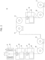
- FIG. 2 is a schematic diagram of a manufacturing apparatus 10 used in a method for manufacturing the colored optical fiber 1 according to the first embodiment.
- the manufacturing apparatus 10 includes a heating apparatus 20, a primary layer covering apparatus 30, a secondary layer covering apparatus 40, a colored layer covering apparatus 50, guide rollers 60, 61 and 62, a bobbin 70 and a winding apparatus 71.
- the manufacturing apparatus 10 is an apparatus for manufacturing the colored optical fiber 1 from the optical fiber base material 6.
- the optical fiber base material 6 is made of quartz glass, for example, and is manufactured by a known method such as a VAD method, an OVD method, or an MCVD method.
- the heating apparatus 20 includes a heater 21.
- the heater 21 may be any heat source such as a tape heater, a ribbon heater, a rubber heater, an oven heater, a ceramic heater, a halogen heater, or the like.
- the end of the optical fiber base material 6 is heated and melted by using the heater 21 arranged around the optical fiber base material 6, and a bare optical fiber 2 is drawn by drawing.
- the primary layer covering apparatus 30 includes a resin application apparatus 31 and an ultraviolet irradiation apparatus 32.
- the resin application apparatus 31 holds a covering material of the primary layer 3 (also referred to as a primary layer material).
- the primary layer material is applied to the bare optical fiber 2 drawn from the optical fiber base material 6 by the resin application apparatus 31.
- the ultraviolet irradiation apparatus 32 is provided under the resin application apparatus 31.
- the ultraviolet irradiation apparatus 32 includes any ultraviolet light source such as a metal halide lamp, a mercury lamp, or an UV-LED.
- the primary layer material is applied to the bare optical fiber 2 by the resin application apparatus 31 and the bare optical fiber 2 enters the ultraviolet irradiation apparatus 32, and the primary layer material is irradiated with ultraviolet light. As a result, the primary layer material containing the ultraviolet curing resin as a main component is cured to form the primary layer 3.
- the secondary layer covering apparatus 40 includes a resin application apparatus 41 and an ultraviolet irradiation apparatus 42.
- the resin application apparatus 41 holds a covering material of the secondary layer 4 (also referred to as a secondary layer material).
- the secondary layer material is applied to the primary layer 3 by the resin application apparatus 41.
- the ultraviolet irradiation apparatus 42 is provided under the resin application apparatus 41.
- the ultraviolet irradiation apparatus 42 may have a configuration similar to that of the ultraviolet irradiation apparatus 32.
- the bare optical fiber 2 enters the ultraviolet irradiation apparatus 42, and the secondary layer material is irradiated with ultraviolet light.
- the secondary layer material containing the ultraviolet curing resin as a main component is cured to form the secondary layer 4.
- the bare optical fiber 2 is guided by the guide roller 60 provided under the secondary layer covering apparatus 40, and wound around the bobbin 70.
- the bare optical fiber 2 covered with the primary layer 3 and the secondary layer 4 is wound around the bobbin once, and then the colored layer 5 is formed.
- the resin application apparatus 31 may be configured to hold the primary layer material and the secondary layer material separately. In this case, the resin application apparatus 31 applies the primary layer material to the bare optical fiber 2, and subsequently applies the secondary layer material to the primary layer material.
- the ultraviolet irradiation apparatus 32 irradiates the primary layer material and the secondary layer material applied to the bare optical fiber 2 with ultraviolet light to form the primary layer 3 and the secondary layer 4. In this case, the manufacturing apparatus 10 does not necessarily need to include the secondary layer covering apparatus 40.
- the bare optical fiber 2 wound around the bobbin 70 is guided by the guide roller 61 and enters the colored layer covering apparatus 50.
- the colored layer covering apparatus 50 includes a resin application apparatus 51 and an ultraviolet irradiation apparatus 52.
- the resin application apparatus 51 holds a covering material of the colored layer 5 (also referred to as a coloring layer material).
- the bare optical fiber 2 covered with the primary layer 3 and the secondary layer 4 is covered with the colored layer material by the resin application apparatus 51.
- the ultraviolet irradiation apparatus 52 is provided under the resin application apparatus 51.
- the ultraviolet irradiation apparatus 52 may be configured similarly to the ultraviolet irradiation apparatus 32 and 42.
- the bare optical fiber 2 covered with the colored layer material on the outer periphery of the secondary layer 4 enters the ultraviolet irradiation apparatus 52, and the bare optical fiber 2 is irradiated with ultraviolet light.
- the colored layer material containing the ultraviolet curing resin as a main component is cured to form the colored layer 5.
- the primary layer 3, the secondary layer 4, and the colored layer 5 are covered with the bare optical fiber 2 to form a colored optical fiber 1.
- the colored optical fiber 1 is guided by the guide roller 62 provided under the colored layer covering apparatus 50 and wound by the winding apparatus 71.
- FIG. 3 is a flowchart of a method for manufacturing the colored optical fiber 1 according to the first embodiment.
- a user installs the optical fiber base material 6 in the manufacturing apparatus 10 (step S101).
- the heater 21 provided in the heating apparatus 20 heats the optical fiber base material 6 and starts drawing the bare optical fiber 2 (step S102).
- the primary layer covering apparatus 30 forms the primary layer 3 by applying a primary layer material containing an ultraviolet curing resin around the drawn bare optical fiber 2, and irradiating the primary layer material with ultraviolet light to form the primary layer 3 (step S103).
- the secondary layer covering apparatus 40 forms the secondary layer 4 by applying a secondary layer material containing an ultraviolet curing resin around the primary layer 3, and irradiating the secondary layer material with ultraviolet light (step S104).
- the colored layer covering apparatus 50 forms the colored layer 5 by applying a colored layer material containing an ultraviolet curing resin around the secondary layer 4, and irradiating the colored layer material with ultraviolet light (step S105).
- a colored optical fiber 1 is obtained.
- step S103 it is not always necessary to irradiate ultraviolet light.
- the primary layer 3 can be cured by irradiation with ultraviolet light in the step of forming the secondary layer 4 (step S104) .
- the ultraviolet light irradiation is performed in the step of forming the primary layer 3 (step S103), the step of forming the secondary layer 4 (step S104), and the step of forming the colored layer 5 (step S105) . Accordingly, after the primary layer 3 is formed, the primary layer 3 is irradiated with ultraviolet light even in the forming of the secondary layer 4 and the colored layer 5, and the primary layer 3 can be cured. More specifically, ultraviolet light transmitted through the secondary layer 4 and the colored layer 5 is absorbed by the primary layer 3, and curing of the primary layer 3 can proceed further. If the ultraviolet curing resin is too cured, the Young's modulus of the primary layer 3 becomes large, and it may be difficult for the primary layer 3 to sufficiently buffer the external force applied to the bare optical fiber 2. This may result in microbend loss.
- the primary layer 3 is cured by polymerization of the ultraviolet curing resin contained in the primary layer material.
- the low molecular weight component contained in the primary layer material is partly volatilized, for example, under high temperature conditions after the drawing step (step S102). By irradiating the primary layer material with ultraviolet light while the primary layer material is at high temperature, polymerization and volatilization of the primary layer material proceed simultaneously.
- the polymerization and volatilization of the primary layer material proceed simultaneously, thereby suppressing the polymerization of the primary layer material. That is, by irradiating the primary layer material with ultraviolet light under the condition that the primary layer material is at a high temperature, progress of curing of the primary layer 3 can be suppressed, and the Young's modulus of the primary layer 3 can be kept small.
- the composition of the primary layer material is changed by volatilization of the primary layer material, and curing of the primary layer 3 is suppressed.
- the composition of the primary layer 3 is changed so as to suppress progress of curing. That is, curing of the primary layer 3 can be suppressed even when the colored optical fiber 1 is irradiated with additional ultraviolet light.
- the method for increasing the temperature of the primary layer material includes, for example, shortening the period from the end of the drawing step (step S102) to the start of the step of covering the primary layer 3 (step S103).
- the primary layer material since the primary layer material is applied around the bare optical fiber 2 at a relatively high temperature, the primary layer material can be irradiated with ultraviolet light in a state where the primary layer material is at a high temperature.
- the method for suppressing the progress of curing of the primary layer 3 is not limited to a method for increasing the temperature of the primary layer material.
- Other methods include, for example, a method for adjusting the amount of additives contained in the primary layer material, and a method for adjusting the amount of ultraviolet light to be irradiated. By arbitrarily selecting or combining these methods, the method can be appropriately set so that the primary layer 3 having the required Young's modulus can be obtained.
- the ultraviolet curing resin used for the primary layer material desirably has a saturated Young's modulus larger than or equal to 0.84 MPa.
- the viscosity of the ultraviolet curing resin having a large saturated Young's modulus is lower than the viscosity of the ultraviolet curing resin having a small saturated Young's modulus. Therefore, for example, the primary layer material can be uniformly applied to the outer periphery of the bare optical fiber 2, and the primary layer can be easily formed.
- An optical fiber ribbon, an apparatus for manufacturing an optical fiber ribbon, and a manufacturing method thereof according to a second embodiment of the present invention will be described.
- Components similar to those of the colored optical fiber 1, the manufacturing apparatus 10 and the manufacturing method for the colored optical fiber 1 according to the first embodiment are denoted by the same reference numerals, and description thereof will be omitted or simplified.
- an optical fiber ribbon composed of the colored optical fiber 1 according to the first embodiment will be described.
- An example of the application of the colored optical fiber according to the first embodiment is not limited to the form of an optical fiber ribbon, and may be, for example, a form of an assembly cable of single fibers in which the colored optical fiber is accommodated by a sheath.
- FIG. 4 is a cross-sectional view of an optical fiber ribbon 100 according to a second embodiment.
- the optical fiber ribbon 100 is formed by bundling a plurality of colored optical fibers 1 in a band shape via an adhesive layer 101.
- the adhesive layer 101 is formed by irradiating a covering material containing an ultraviolet curing resin with ultraviolet light to be cured.
- the ultraviolet curing resin forming the adhesive layer 101 is made of a resin similar to the ultraviolet curing resin forming the primary layer 3, the secondary layer 4, and the colored layer 5.
- the colored optical fiber 1 can be bundled in high density by taking the form of an optical fiber ribbon 100.
- the optical fiber ribbon 100 is not limited to the configuration illustrated in FIG. 4 . Further, the optical fiber ribbon 100 may take the form of a ribbon cable accommodated by a sheath, and the colored optical 1 may take an intermittent adhesive structure in which the colored optical fiber 1 is intermittently bonded in the longitudinal direction.
- FIG. 5 is a schematic diagram of a ribbon forming apparatus 80 used in a method for manufacturing the optical fiber ribbon 100 according to the second embodiment.
- the ribbon forming apparatus 80 holds a covering material of the adhesive layer 101 (also referred to as an adhesive layer material).
- the ribbon forming apparatus 80 is provided with an ultraviolet light source similar to the ultraviolet light sources provided in the ultraviolet irradiation apparatuses 32, 42, and 52.
- a plurality of prepared colored optical fibers 1 enter the ribbon forming apparatus 80, and the adhesive layer material is applied thereto.
- the colored optical fiber 1 applied to the adhesive layer material is bundled together with a plurality of other colored optical fibers 1 applied to the adhesive layer material.
- the bundled plurality of colored optical fibers 1 are irradiated with ultraviolet light by an ultraviolet light source provided in the ribbon forming apparatus 80.
- the adhesive layer material containing the ultraviolet curing resin as a main component is cured to form the adhesive layer 101.
- a plurality of colored optical fibers 1 arranged in parallel are connected via the adhesive layer 101. In this way, the optical fiber ribbon 100 is formed from the colored optical fiber 1.
- FIG. 6 is a flowchart of the method for manufacturing the optical fiber ribbon 100 according to the second embodiment. Steps S101 to S105 are similar to those in the first embodiment.
- a ribbon forming step of the colored optical fiber 1 is performed. That is, after the colored layer 5 is formed in step S105, the ribbon forming apparatus 80 applies an ultraviolet curing resin to a plurality of prepared colored optical fibers 1, and irradiates the ultraviolet curing resin with ultraviolet light to connect the plurality of colored optical fibers 1 (step S106). Thus, the optical fiber ribbon 100 is manufactured.
- the colored optical fiber 1 is irradiated with ultraviolet light. Further, the colored optical fiber 1 can suppress curing of the primary layer 3 even when additional ultraviolet irradiation is performed after manufacturing. Therefore, even in the ribbon forming step of the colored optical fiber, curing of the primary layer 3 due to irradiation with ultraviolet light can be suppressed. Therefore, it is possible to obtain the optical fiber ribbon 100 in which an increase in microbend loss in the ribbon forming step is suppressed.
- Table 1 illustrates Young's modulus of the primary layer and evaluations of the microbend loss in Examples and Comparative Examples of the colored optical fiber or the optical fiber ribbon. That is, Table 1 illustrates saturated Young's modulus (MPa), Young's modulus (MPa), Young's modulus/saturated Young's modulus (%), Young's modulus after additional ultraviolet irradiation (MPa), Young's modulus after additional ultraviolet irradiation/saturated Young's modulus (%), the amount of change in Young's modulus /saturated Young's modulus (%), and evaluations of the microbend loss of the primary layer 3 in Examples 1 to 9 and Comparative Examples 1 and 2.
- the “saturated Young's modulus” in Table 1 is the Young's modulus when an ultraviolet curing resin forming the primary layer 3 is formed and irradiated with ultraviolet light at room temperature using a mercury lamp, UV-LED, or the like to be completely cured.
- the "Young's modulus” in Table 1 is ISM (In Situ Modulus) of the primary layer 3 of the colored optical fiber 1. In the present specification, ISM is defined as measured by the following method.
- the primary layer 3 and the secondary layer 4 of the intermediate portion of the optical fiber serving as a sample are peeled off by a length of several millimeters, and then a load F is applied to one end of the optical fiber on which the covering layer is formed.
- a displacement ⁇ of the primary layer 3 at the boundary between the portion where the covering layer is peeled off and the portion where the covering layer is formed is read by a microscope.
- the load F is 10, 20, 30, 50, and 70 gf (that is, 98, 196, 294, 490, and 686 mN sequentially)
- a graph of the displacement ⁇ with respect to the load F is created.
- the unit of P-ISM is [MPa].
- F/ ⁇ is an inclination indicated by a graph of the displacement ( ⁇ ) [ ⁇ m] with respect to the load (F) [gf]
- 1 is a sample length (for example, 10 mm)
- DP/DG is a ratio between the outer diameter (DP) [um] of the primary layer 3 and the outer diameter (DG) [ ⁇ m] of the cladding portion of the optical fiber. Therefore, in the case of calculating P-ISM from F, ⁇ , and 1 used, it is necessary to perform predetermined unit conversion.
- the outer diameter of the primary layer 3 and the outer diameter of the cladding portion can be measured by observing the cross section of the optical fiber cut by the fiber cutter with a microscope.
- the "Young's modulus after additional ultraviolet irradiation” in Table 1 is the ISM of the primary layer 3 when the manufactured colored optical fiber 1 was additionally irradiated with ultraviolet light at 1000 mW/cm2 and 500 mJ/cm2 using D bulb.
- “change amount of Young's modulus/saturated Young's modulus” represents a ratio between a change amount of Young's modulus before and after the additional irradiation with ultraviolet light and the saturated Young's modulus.
- the “change amount of Young's modulus” is a value of a change amount from the "Young's modulus” to the "Young's modulus after additional ultraviolet irradiation”.
- Evaluation 1 indicates whether or not the microbend loss in the colored optical fiber 1 before additional irradiation with ultraviolet light meets the standard (smaller than or equal to 0.15 dB/km).
- Evaluation 2 represents whether or not the microbend loss in the colored optical fiber 1 after additional irradiation with ultraviolet light meets the standard (smaller than or equal to 0.15 dB/km).
- the Evaluations 1 and 2 are defined to be good (OK), and when the microbend loss does not meet the standard, the evaluations 1 and 2 are defined to be poor (NG).
- the transmission loss of the optical fiber in the state B does not include the microbend loss, and is considered to be a transmission loss inherent to the optical fiber itself.
- This measuring method is similar to the fixed diameter drum method defined in JIS C6823:2010. This measuring method is also referred to as a sandpaper method. Further, in this measuring method, since the transmission loss is measured at a wavelength of 1550 nm, the following microbend loss is also a value at a wavelength of 1550 nm.
- the effective core cross-sectional area (effective core cross-sectional area) is an index indicating the easiness of microbend loss of the optical fiber.
- the effective core cross-sectional area is a value at a wavelength of 1550 nm
- MFD is a mode field diameter (um)
- k is a constant.
- the effective core cross-sectional area represents an area of a portion through which light having a predetermined intensity passes in a cross-section orthogonal to the axis of the bare optical fiber 2.
- the colored optical fiber 1 according to the embodiment of the present invention includes a primary layer 3 capable of effectively buffering an external force applied to the colored optical fiber 1. Therefore, by sufficiently buffering the external force applied to the colored optical fiber 1 by the primary layer 3, the external force applied to the bare optical fiber 2 can be sufficiently reduced. Thus, even when the effective core cross-sectional area of the bare optical fiber 2 is large, the microbend loss of the optical fiber can be effectively suppressed.
- the colored optical fiber 1 of Examples 1 to 9 and Comparative Examples 1 and 2 preferably have an effective core cross-sectional area larger than or equal to 100 ⁇ m 2 and smaller than or equal to 160 ⁇ m 2 , for example, larger than or equal to 120 ⁇ m 2 and smaller than or equal to 160 ⁇ m 2 .
- an effective core cross-sectional area larger than or equal to 100 ⁇ m 2 and smaller than or equal to 160 ⁇ m 2 , for example, larger than or equal to 120 ⁇ m 2 and smaller than or equal to 160 ⁇ m 2 .
- Examples 1 and 2 a primary layer material having a saturated Young's modulus of 0.84 MPa was used.
- the primary layer material was ultraviolet-cured until Young's modulus of Examples 1 and 2 became 0.58 MPa and 0.54 MPa, respectively, and the ratio of the Young's modulus to the saturated Young's modulus was 68.7% and 63.9%.
- Young's modulus after the additional ultraviolet irradiation was 0.59 MPa and 0.54 MPa, and the ratio of the Young's modulus after additional ultraviolet irradiation to the saturated Young's modulus was 69.9% and 64.0%.
- the ratio of a change amount of Young's modulus to the saturated Young's modulus was 1.2% and 0.0%, and in any case, the ratio was smaller than or equal to 16%.
- the microbend loss before and after the additional irradiation with ultraviolet light was smaller than or equal to 0.15 dB/km, and the Evaluations 1 and 2 were good (OK).
- Examples 3, 4, and 5 a primary layer material having a saturated Young's modulus of 1.30 MPa was used.
- the primary layer material was ultraviolet-cured until Young's modulus of Examples 3, 4, and 5 became 0.39 MPa, 0.30 MPa, and 0.70 MPa, respectively, and the ratio of the Young's modulus to the saturated Young's modulus was 30.3%, 23.1%, and 53.8%.
- Young's modulus after the additional ultraviolet irradiation was 0.43 MPa, 0.33 MPa and 0.90 MPa, and the ratio of the Young's modulus after additional ultraviolet irradiation to the saturated Young's modulus was 32.7%, 25.4% and 69.2%.
- the ratio of a change amount of Young's modulus to the saturated Young's modulus was 3.1%, 2.3%, and 15.4%, and in any case, the ratio was smaller than or equal to 16%.
- the microbend loss before and after the additional irradiation with ultraviolet light was smaller than or equal to 0.15 dB/km, and the Evaluations 1 and 2 were good (OK).
- Examples 6 and 7 a primary layer material having a saturated Young's modulus of 1.74 MPa was used.
- the primary layer material was ultraviolet-cured until Young's modulus of Examples 6 and 7 became 1.11 MPa and 0.82 MPa, respectively, and the ratio of the Young's modulus to the saturated Young's modulus was 63.6% and 47.0%.
- Young's modulus after additional ultraviolet irradiation was 1.12 MPa and 0.89 MPa, and the ratio of the Young's modulus after additional ultraviolet irradiation to the saturated Young's modulus was 64.1% and 50.9%.
- the ratio of a change amount of Young's modulus to the saturated Young's modulus was 0.6% and 4.0%.
- the microbend loss before and after the additional irradiation with ultraviolet light was smaller than or equal to 0.15 dB/km, and the Evaluations 1 and 2 were good (OK).
- Examples 8 and 9 a primary layer material having a saturated Young's modulus of 2.60 MPa was used.
- the primary layer material was ultraviolet-cured until Young's modulus of Examples 8 and 9 became 0.90 MPa and 0.71 MPa, respectively, and the ratio of the Young's modulus to the saturated Young's modulus was 34.5% and 27.4%.
- Young's modulus after additional ultraviolet irradiation was 1.04 MPa and 1.00 MPa, and the ratio of the Young's modulus after additional ultraviolet irradiation to the saturated Young's modulus was 40.0% and 38.3%.
- the ratio of a change amount of Young's modulus to the saturated Young's modulus was 5.4% and 11.2%.
- the microbend loss before and after the additional irradiation with ultraviolet light was smaller than or equal to 0.15 dB/km, and the Evaluations 1 and 2 were good (OK).
- Comparative Example 1 a primary layer material having a saturated Young's modulus of 1.30 MPa was used, and the primary layer material was cured until Young's modulus became 0.19 MPa.
- the ratio of a change amount of Young's modulus to the saturated Young's modulus was 14.4%, which is smaller than 70%, whereas the ratio of Young's modulus after the additional ultraviolet irradiation to the saturated Young's modulus was 97.7%, which is larger than 70%.
- the ratio of a change amount of Young's modulus before and after the additional ultraviolet irradiation to the saturated Young's modulus was 83.1%.
- the microbend loss was 0.15 dB/km and Evaluation 1 was good (OK), whereas the microbend loss after the additional irradiation with ultraviolet light was larger than 0.15 dB/km and Evaluation 2 was poor (NG) .
- Comparative Example 2 a primary layer material having a saturated Young's modulus of 1.30 MPa was used, and the primary layer material was cured until Young's modulus became 0.95 MPa.
- the ratio of a change amount of Young's modulus to the saturated Young's modulus was 73.3%, larger than 70%.
- the ratio of the Young's modulus after additional ultraviolet irradiation to the saturated Young's modulus was 99.1%, larger than 70%.
- the ratio of a change amount of Young's modulus before and after the additional ultraviolet irradiation to the saturated Young's modulus was 26.2%.
- the microbend loss before and after the additional irradiation with ultraviolet light is larger than 0.15 dB/km, and the Evaluations 1 and 2 were both poor (NG).
- FIG. 7 is a diagram illustrating a relationship between the ratio (%) of Young's modulus to saturated Young's modulus and the ratio (%) of Young's modulus after additional ultraviolet irradiation to saturated Young's modulus and microbend loss (dB/km) in Examples 1 to 9 and Comparative Examples 1 and 2 in Table 1.
- the ratio of the Young's modulus to the saturated Young's modulus is preferably smaller than 70%.
- the saturated Young's modulus of the primary layer 3 preferably has a relatively large saturated Young's modulus larger than or equal to 0.84 MPa. Since the ultraviolet curing resin having a large saturated Young's modulus has a relatively low viscosity, handling is easy. For this reason, it is possible to obtain a manufacturing advantage, for example, that the uniform primary layer 3 can be easily formed.
- the primary layer 3 is exposed to a high temperature in the drawing step, a curing reaction due to additional ultraviolet irradiation can be suppressed.
- the ultraviolet curing resin having a large saturated Young's modulus even when the primary layer 3 is exposed to a high temperature in the drawing step, it is possible to prevent the Young's modulus from becoming too small.
- the ratio of the Young's modulus after the additional ultraviolet irradiation to the saturated Young's modulus is preferably smaller than 70%, and the ratio of the change amount of the Young's modulus before and after the additional ultraviolet irradiation to the saturated Young's modulus is preferably smaller than or equal to 16%.
- the present invention is not limited to the embodiments described above, and various modifications are possible.
- an example in which a configuration of a part of any embodiment is added to another embodiment or an example in which a configuration of a part of another embodiment is substituted is also an embodiment of the present invention.
- a known technique or a known technique in the technical field can be appropriately applied to a specific description or a portion not illustrated in the embodiments.
Landscapes
- Chemical & Material Sciences (AREA)
- Life Sciences & Earth Sciences (AREA)
- Physics & Mathematics (AREA)
- Engineering & Computer Science (AREA)
- Materials Engineering (AREA)
- General Chemical & Material Sciences (AREA)
- General Life Sciences & Earth Sciences (AREA)
- Chemical Kinetics & Catalysis (AREA)
- Geochemistry & Mineralogy (AREA)
- Organic Chemistry (AREA)
- Optics & Photonics (AREA)
- General Physics & Mathematics (AREA)
- Electromagnetism (AREA)
- Composite Materials (AREA)
- Manufacturing & Machinery (AREA)
- Optical Fibers, Optical Fiber Cores, And Optical Fiber Bundles (AREA)
- Surface Treatment Of Glass Fibres Or Filaments (AREA)
Applications Claiming Priority (2)
| Application Number | Priority Date | Filing Date | Title |
|---|---|---|---|
| JP2020181724 | 2020-10-29 | ||
| PCT/JP2021/039503 WO2022092089A1 (ja) | 2020-10-29 | 2021-10-26 | 光ファイバ着色心線、光ファイバリボン、単心ファイバの集合体ケーブル、リボンケーブルおよびこれらの製造方法 |
Publications (2)
| Publication Number | Publication Date |
|---|---|
| EP4238946A1 true EP4238946A1 (de) | 2023-09-06 |
| EP4238946A4 EP4238946A4 (de) | 2024-08-07 |
Family
ID=81383944
Family Applications (1)
| Application Number | Title | Priority Date | Filing Date |
|---|---|---|---|
| EP21886207.6A Withdrawn EP4238946A4 (de) | 2020-10-29 | 2021-10-26 | Farbiger glasfaserkerndraht, glasfaserband, einadriges fasermontagekabel, bandkabel und verfahren zur herstellung davon |
Country Status (4)
| Country | Link |
|---|---|
| US (1) | US20230257301A1 (de) |
| EP (1) | EP4238946A4 (de) |
| JP (1) | JP7688041B2 (de) |
| WO (1) | WO2022092089A1 (de) |
Families Citing this family (1)
| Publication number | Priority date | Publication date | Assignee | Title |
|---|---|---|---|---|
| JP7727598B2 (ja) * | 2022-08-05 | 2025-08-21 | 古河電気工業株式会社 | 光ファイバ着色心線及びその製造方法 |
Family Cites Families (12)
| Publication number | Priority date | Publication date | Assignee | Title |
|---|---|---|---|---|
| JPH0723239B2 (ja) * | 1986-03-03 | 1995-03-15 | 日本電信電話株式会社 | 紫外線硬化樹脂被覆光フアイバの高速被覆方法 |
| JP2547773B2 (ja) * | 1987-06-16 | 1996-10-23 | 住友電気工業株式会社 | 光フアイバの製造方法 |
| JPH0387706A (ja) * | 1989-06-26 | 1991-04-12 | Sumitomo Electric Ind Ltd | 光ファイバ心線 |
| JPH0442838A (ja) * | 1990-06-05 | 1992-02-13 | Sumitomo Electric Ind Ltd | 光硬化型樹脂被覆光ファイバの製造方法 |
| JPH0769686A (ja) * | 1993-08-31 | 1995-03-14 | Dainippon Ink & Chem Inc | 光ファイバ被覆用紫外線硬化型樹脂組成物 |
| US5977202A (en) * | 1997-09-22 | 1999-11-02 | Dsm N.V. | Radiation-curable compositions having fast cure speed and good adhesion to glass |
| JP2005162522A (ja) | 2003-12-01 | 2005-06-23 | Sumitomo Electric Ind Ltd | 被覆線条体の製造方法、及び被覆線条体製造装置 |
| US8600206B2 (en) * | 2008-11-07 | 2013-12-03 | Draka Comteq, B.V. | Reduced-diameter optical fiber |
| JP5790942B2 (ja) * | 2012-06-22 | 2015-10-07 | 住友電気工業株式会社 | 光ファイバ素線 |
| EP3521883A4 (de) | 2016-09-30 | 2020-05-13 | Fujikura Ltd. | Farbiger glasfaserkern, glasfaserkabel und verfahren zur herstellung eines farbigen glasfaserkerns |
| CA3038637C (en) | 2016-09-30 | 2021-05-04 | Fujikura Ltd. | Optical fiber ribbon, optical fiber cable, and method of manufacturing optical fiber ribbon |
| JP6901518B2 (ja) | 2019-04-25 | 2021-07-14 | 日本電子株式会社 | 荷電粒子線装置および荷電粒子線装置の光学系の制御方法 |
-
2021
- 2021-10-26 EP EP21886207.6A patent/EP4238946A4/de not_active Withdrawn
- 2021-10-26 WO PCT/JP2021/039503 patent/WO2022092089A1/ja not_active Ceased
- 2021-10-26 JP JP2022559162A patent/JP7688041B2/ja active Active
-
2023
- 2023-04-24 US US18/305,485 patent/US20230257301A1/en active Pending
Also Published As
| Publication number | Publication date |
|---|---|
| WO2022092089A1 (ja) | 2022-05-05 |
| JPWO2022092089A1 (de) | 2022-05-05 |
| US20230257301A1 (en) | 2023-08-17 |
| EP4238946A4 (de) | 2024-08-07 |
| JP7688041B2 (ja) | 2025-06-03 |
Similar Documents
| Publication | Publication Date | Title |
|---|---|---|
| JP6490805B2 (ja) | 光ファイバテープ心線及び光ファイバケーブル | |
| JP7384827B2 (ja) | 小径の低減衰光ファイバ | |
| KR100889698B1 (ko) | 피복 광섬유, 이를 사용하는 광섬유 테이프 심선 및광섬유 유니트 | |
| JP4049154B2 (ja) | 光ファイバテープ心線 | |
| JP6927222B2 (ja) | 光ファイバ及び光ファイバの製造方法 | |
| EP3162775B1 (de) | Verfahren zur herstellung optischer fasern und vorrichtung zur herstellung optischer fasern | |
| KR20000070290A (ko) | 피복된 광섬유 및 이의 제조방법 | |
| EP2048529B1 (de) | Optische faser | |
| US20230257301A1 (en) | Colored optical fiber, optical fiber ribbon, assembly cable of single fibers, ribbon cable and method for manufacturing the same | |
| JP7536670B2 (ja) | 光ファイバ心線の製造方法 | |
| EP4306494A1 (de) | Farbiger glasfaserkerndraht, glasfaserband, einadriges faseranordnungskabel, glasfaserbandkabel und verfahren zur herstellung davon | |
| JP2950264B2 (ja) | 光ファイバテープ心線の製造方法 | |
| JP6046021B2 (ja) | オーバーコート心線及び当該オーバーコート心線を備えた光ファイバケーブル | |
| CN117642367A (zh) | 光纤的制造方法以及光纤 | |
| WO2002075419A1 (fr) | Coeur rubane de fibre optique de type fendu | |
| US20240116808A1 (en) | Colored optical fiber, optical fiber ribbon, optical fiber ribbon cable and method for manufacturing the same | |
| JPWO2020054753A1 (ja) | 光ファイバ心線及び光ファイバケーブル | |
| JP2025182952A (ja) | 光ファイバ素線の製造装置および光ファイバ素線の製造方法 | |
| JP7508437B2 (ja) | 光ファイバ着色心線及び光ファイバ着色心線の製造方法 | |
| JP7640440B2 (ja) | 光ファイバリボン及び光ファイバリボンの製造方法 | |
| JP7704693B2 (ja) | 光ファイバリボン及び光ファイバリボンの製造方法 | |
| US12617708B2 (en) | Method for manufacturing optical fiber | |
| JP2025030778A (ja) | 光ファイバ心線および光ファイバ心線の製造方法 | |
| JP2025030756A (ja) | 光ファイバ心線および光ファイバ心線の製造方法 | |
| JP2025086185A (ja) | 光ファイバリボンおよび光ファイバリボンの製造方法 |
Legal Events
| Date | Code | Title | Description |
|---|---|---|---|
| STAA | Information on the status of an ep patent application or granted ep patent |
Free format text: STATUS: THE INTERNATIONAL PUBLICATION HAS BEEN MADE |
|
| PUAI | Public reference made under article 153(3) epc to a published international application that has entered the european phase |
Free format text: ORIGINAL CODE: 0009012 |
|
| STAA | Information on the status of an ep patent application or granted ep patent |
Free format text: STATUS: REQUEST FOR EXAMINATION WAS MADE |
|
| 17P | Request for examination filed |
Effective date: 20230421 |
|
| AK | Designated contracting states |
Kind code of ref document: A1 Designated state(s): AL AT BE BG CH CY CZ DE DK EE ES FI FR GB GR HR HU IE IS IT LI LT LU LV MC MK MT NL NO PL PT RO RS SE SI SK SM TR |
|
| DAV | Request for validation of the european patent (deleted) | ||
| DAX | Request for extension of the european patent (deleted) | ||
| A4 | Supplementary search report drawn up and despatched |
Effective date: 20240710 |
|
| RIC1 | Information provided on ipc code assigned before grant |
Ipc: G02B 6/44 20060101ALI20240704BHEP Ipc: G02B 6/02 20060101ALI20240704BHEP Ipc: C03C 25/6226 20180101ALI20240704BHEP Ipc: C03C 25/50 20060101ALI20240704BHEP Ipc: C03C 25/285 20180101ALI20240704BHEP Ipc: C03C 25/1065 20180101AFI20240704BHEP |
|
| STAA | Information on the status of an ep patent application or granted ep patent |
Free format text: STATUS: EXAMINATION IS IN PROGRESS |
|
| 17Q | First examination report despatched |
Effective date: 20251124 |
|
| STAA | Information on the status of an ep patent application or granted ep patent |
Free format text: STATUS: THE APPLICATION HAS BEEN WITHDRAWN |
|
| 18W | Application withdrawn |
Effective date: 20260316 |