EP4234829A2 - Wandanordnung - Google Patents
Wandanordnung Download PDFInfo
- Publication number
- EP4234829A2 EP4234829A2 EP23180296.8A EP23180296A EP4234829A2 EP 4234829 A2 EP4234829 A2 EP 4234829A2 EP 23180296 A EP23180296 A EP 23180296A EP 4234829 A2 EP4234829 A2 EP 4234829A2
- Authority
- EP
- European Patent Office
- Prior art keywords
- support
- blocks
- recesses
- block
- protrusions
- Prior art date
- Legal status (The legal status is an assumption and is not a legal conclusion. Google has not performed a legal analysis and makes no representation as to the accuracy of the status listed.)
- Granted
Links
Images


Classifications
-
- E—FIXED CONSTRUCTIONS
- E04—BUILDING
- E04B—GENERAL BUILDING CONSTRUCTIONS; WALLS, e.g. PARTITIONS; ROOFS; FLOORS; CEILINGS; INSULATION OR OTHER PROTECTION OF BUILDINGS
- E04B2/00—Walls, e.g. partitions, for buildings; Wall construction with regard to insulation; Connections specially adapted to walls
- E04B2/02—Walls, e.g. partitions, for buildings; Wall construction with regard to insulation; Connections specially adapted to walls built-up from layers of building elements
- E04B2/14—Walls having cavities in, but not between, the elements, i.e. each cavity being enclosed by at least four sides forming part of one single element
- E04B2/16—Walls having cavities in, but not between, the elements, i.e. each cavity being enclosed by at least four sides forming part of one single element using elements having specially-designed means for stabilising the position
-
- E—FIXED CONSTRUCTIONS
- E04—BUILDING
- E04B—GENERAL BUILDING CONSTRUCTIONS; WALLS, e.g. PARTITIONS; ROOFS; FLOORS; CEILINGS; INSULATION OR OTHER PROTECTION OF BUILDINGS
- E04B2/00—Walls, e.g. partitions, for buildings; Wall construction with regard to insulation; Connections specially adapted to walls
- E04B2/02—Walls, e.g. partitions, for buildings; Wall construction with regard to insulation; Connections specially adapted to walls built-up from layers of building elements
- E04B2/04—Walls having neither cavities between, nor in, the solid elements
- E04B2/06—Walls having neither cavities between, nor in, the solid elements using elements having specially-designed means for stabilising the position
- E04B2/08—Walls having neither cavities between, nor in, the solid elements using elements having specially-designed means for stabilising the position by interlocking of projections or inserts with indentations, e.g. of tongues, grooves, dovetails
-
- E—FIXED CONSTRUCTIONS
- E04—BUILDING
- E04B—GENERAL BUILDING CONSTRUCTIONS; WALLS, e.g. PARTITIONS; ROOFS; FLOORS; CEILINGS; INSULATION OR OTHER PROTECTION OF BUILDINGS
- E04B2/00—Walls, e.g. partitions, for buildings; Wall construction with regard to insulation; Connections specially adapted to walls
- E04B2/02—Walls, e.g. partitions, for buildings; Wall construction with regard to insulation; Connections specially adapted to walls built-up from layers of building elements
- E04B2002/0202—Details of connections
- E04B2002/0243—Separate connectors or inserts, e.g. pegs, pins or keys
- E04B2002/0245—Pegs or pins
-
- E—FIXED CONSTRUCTIONS
- E04—BUILDING
- E04B—GENERAL BUILDING CONSTRUCTIONS; WALLS, e.g. PARTITIONS; ROOFS; FLOORS; CEILINGS; INSULATION OR OTHER PROTECTION OF BUILDINGS
- E04B2/00—Walls, e.g. partitions, for buildings; Wall construction with regard to insulation; Connections specially adapted to walls
- E04B2/02—Walls, e.g. partitions, for buildings; Wall construction with regard to insulation; Connections specially adapted to walls built-up from layers of building elements
- E04B2002/0256—Special features of building elements
- E04B2002/028—Spacers between building elements
- E04B2002/0282—Separate spacers
-
- E—FIXED CONSTRUCTIONS
- E04—BUILDING
- E04B—GENERAL BUILDING CONSTRUCTIONS; WALLS, e.g. PARTITIONS; ROOFS; FLOORS; CEILINGS; INSULATION OR OTHER PROTECTION OF BUILDINGS
- E04B2/00—Walls, e.g. partitions, for buildings; Wall construction with regard to insulation; Connections specially adapted to walls
- E04B2/02—Walls, e.g. partitions, for buildings; Wall construction with regard to insulation; Connections specially adapted to walls built-up from layers of building elements
- E04B2002/0256—Special features of building elements
- E04B2002/028—Spacers between building elements
- E04B2002/0284—Spacers between building elements forming a unity with the building elements
Definitions
- the present disclosure relates to construction techniques, in particular methods and devices for building at least part of a wall and constructions comprising such wall or wall part. More in particular, the present disclosure relates to building walls, in particular dry walls.
- Construction of walls from construction blocks using bricks and mortar and the like is generally known. Dry wall constructions are also known.
- a wall and an assembly for building at least part of the wall are provided.
- the wall and the assembly comprises building blocks and support blocks.
- Each building block comprises opposite first and second faces, both comprising a plurality of recesses arranged spaced from each other.
- Each support block comprises a body and a plurality of protrusions extending from opposite top and bottom sides of the body.
- Each recess of the plurality of recesses comprises a recess support structure and each protrusion of the plurality of protrusion comprises a protrusion support structure.
- the recesses and protrusions are arranged in a matching pattern.
- the building blocks and support blocks support each other, so that the wall may reach a desired height, and they interengage and interlock each other, defining relative positions within a layer fortifying the layer and therewith fortifying the wall as a whole.
- tolerances are defined by the interplay of (the recesses can protrusions of, respectively,) the building blocks and support blocks, rather than just the outside shape, structure and/or texture of the building blocks and/or support blocks as a whole.
- Each support block may have a length, a width, and a height, in, respectively, a length direction L, a width direction W, and a height direction H, and the protrusions may be spaced at least in the length direction L of the support block.
- the recesses are accordingly distributed in the faces.
- the pattern in which the recesses and protrusions are arranged may be limited to specific pairs of a building block and a support block or larger groups of blocks.
- One or more blocks (building block or support block, respectively) may at least partly overlap plural adjacent blocks (support block or building block, respectively), e.g. by staggered arrangement and/or by one block having a length and/or width different from a length and/or width of an adjacent block with which it is operably coupled by cooperation of their respective protrusion and recesses.
- a positioning and/or interlocking effect in the length and/or width direction may be achieved in a wall portion constructed with the assembly.
- each building block comprises a plurality of recesses arranged spaced from each other in at least one of the width and height directions
- the assembly comprises matching support blocks.
- the recess support structures are formed with respect to one reference.
- the reference preferably is or identifies a plane, more preferably a midplane of the building block.
- At least some of the recesses may be formed in the building block by cutting.
- Cutting techniques e.g. one or more of hacking, sawing, milling, drilling, grinding, polishing, etching, etc. have proven to allow reliable manufacturing for forming recesses in building material, which itself may have a rough outer shape.
- Milling and/or sawing can generally be performed at great speed also on site in a construction site.
- the building block and the reference are preferably positioned and oriented with respect to each other in the same predetermined position and orientation in at least one relative direction, more preferably being in the same relative position and orientation, so that the reference relates to positions and orientations with respect to the building block in a predetermined and reliable manner.
- the support structures are formed as mated structures; e.g. at least flat or conical surfaces.
- each recess support structure is a support surface and defines a recess support plane.
- each protrusion support structure is a support surface and defines a protrusion support plane.
- all support structures of the plurality of recesses of a building block in at least one of the first and second faces define a common first plane and/or second plane, respectively.
- the first plane and second plane are parallel. In an embodiment, the first plane and second plane may coincide.
- all protrusion support structures of the plurality of protrusions of a support block protruding in one direction from the body define a common first support plane, more preferably all protrusion support structures of the plurality of protrusions of a support block protruding in the opposite direction from the body define a common second support plane.
- the first and second support planes are parallel.
- At least the building blocks are separate from each other and preferably, in each vertical pair the respective blocks do not support each other apart from at the support structures, e.g. support surfaces, preventing interference with the accurate positioning governed by the support structures.
- the support structures of a recess may be formed by the bottom of the recess.
- first and second recesses By forming the first and second recesses to the same reference, accurate control over the position and/or orientation of the respective support surfaces is facilitated.
- the relative positions and/or orientations of the recesses can be defined to a high precision at a relatively low cost.
- the support blocks may be made to accuracy by the same techniques as the building blocks or other techniques providing uniformity, wherein the uniformity may be masked by the building blocks. Cost benefits due to the speed and ease of manufacturing the building blocks, support blocks and the assembly as a whole are considered to outweigh possible elevated costs for manufacturing the building blocks and support blocks over traditional materials like (mortar and) bricks without further processing thereof.
- the recesses in at least one of the first face and the second face extend parallel to each other. In an embodiment, the recesses in at least one of the first face and the second face extend perpendicular to the first and/or second face, respectively. Each recess may extend along an axis, the axis may extend perpendicular to the first and/or second face.
- the protrusions on at least one of the first and second sides extend parallel to each other. In an embodiment, the protrusions in at least one of the first side and the second side extend perpendicular to the first and/or second side, respectively. Each protrusion may extend along an axis, the axis may extend perpendicular to the first and/or second side.
- At least some recesses in at least one of the first face and at least some recesses in the second face extend coaxial to each other.
- At least some protrusions on the first side and at least some protrusions the second side extend coaxial to each other.
- construction forces and/or stresses may be transmitted linearly, which may fortify a wall relative to curved or meandering distributions of relatively elevated forces and/or stresses.
- At least some of the recesses have a shape, in a cross section generally parallel to the first face and/or second face, that is at least one of circular, annular and cylindrical.
- the protrusions have a shape, in a cross section generally parallel to the first side and/or second side that is at least one of circular, annular and cylindrical.
- At least some of the recesses have a tapering or conical shape, in a direction generally perpendicular to the first face and/or second face.
- the protrusions have a tapering or conical shape, in a direction generally perpendicular to the first face and/or second face.
- Such embodiments each may one or more of facilitate construction of a wall, providing guidance for assembling a wall, and assisting distribution of construction forces and/or stresses.
- the recesses preferably all recesses, have an elongated slot shape in the respective face, having a relatively large size (i.e. being relatively long) in a longitudinal direction and a relatively small size (i.e. being relatively short) in a transverse direction perpendicular to the longitudinal direction.
- the longitudinal and transverse directions preferably each extend generally parallel to a respective pair of opposite faces, and/or parallel to reference planes of the building block.
- the longitudinal direction may extend generally parallel to a side face of the building block in length direction, e.g. a front face and/or a rear face, and the transverse direction may extend generally parallel to a side face of the building block in width direction, e.g. an end face.
- the elongated recesses preferably all, have their longitudinal directions parallel to each other and preferably then being in one line.
- at least some of the recesses, preferably all have their transverse directions parallel to each other and more preferably then in one line.
- Elongated recesses enable adjustment in the direction of elongation of the position of the building block relative to (the protrusions of) a support block, when coupled.
- the size of the elongated recesses determines the available amount of adjustment and therewith the restriction of the relative movement of the respective blocks in the mutually perpendicular directions generally parallel to layers of coupled blocks. This enables meeting construction tolerances while accommodating building block tolerances.
- the shape and size in one direction, preferably the longitudinal direction, of an elongated recess may be significantly larger (i.e. being 2-5 times longer) than a size in corresponding direction of a protrusion of a support block.
- the shape and size in another direction, preferably the transverse direction, of an elongated recess may be approximately equal to a size in corresponding direction of a protrusion of a support block.
- relative adjustment in one direction may be enabled and/or may be larger whereas adjustment in another direction may be prevented and/or may be more limited.
- adjustment may be limited essentially in one direction only and over a restricted length, determined by the size and position of the recesses in combination with the size and position of the protrusions accommodated therein.
- Such adjustment options may facilitate accepting manufacturing tolerances of building blocks and/or support blocks in one or two directions.
- the elongated recesses preferably extend into the building block in one direction and are enclosed in five directions (i.e. only opening to one face of the building block) so that stacked building blocks appear essentially intact and the recesses do not open to a side face.
- elongated recesses may be cut by milling techniques. Milling an elongated recess to a predetermined depth may be more easy and accurate than drilling a recess with constant diameter (cylindrical hole), in particular with respect to one or more of:
- the latter may be desired for providing a flat support surface, which may be preferred to provide a constant support height when adjusting a relative position or the building block and support block.
- the body of one or more of the support blocks may comprise one or more openings. This can save material and weight.
- the body and at least some of the protrusions of one or more of the support blocks may be formed unitary.
- Adjacent support blocks may be connected together within one support block layer.
- support blocks may comprise connectors for mating with an associated connector on another support block.
- the connectors are symmetric and/or all support blocks are provided with identical connectors or connector pairs e.g. comprising one connector on one side and a mated counterconnector on an opposite side.
- One or more of the support blocks may comprise one or more holes for accommodating a protrusion of an adjacent support block.
- adjacent support blocks may be connected by concatenation.
- the assembly may comprise one or more support links for interconnecting adjacent support blocks, e.g. by comprising one or more holes for accommodating a protrusion of an adjacent support block, being generally similar to a support block however not comprising support protrusions.
- the connectors and/or the holes and protrusions may preferably be sized matchingly, e.g. protrusions and holes fitting each other accurately.
- a support block layer may be assembled from a series of connected support blocks and/or from a series of support blocks and associated links.
- Each combination of connectors in particular a pair of protrusion and hole, may have a predetermined play.
- the play may be limited down to predetermined tolerances as defined by manufacturing tolerances of the support blocks and/or links; since these may be moulded the manufacturing tolerances may be very tight.
- the play may be of predetermined size as a desired proportion to manufacturing tolerances and/or design tolerances of building blocks and/or a wall. Note that since the building blocks and support blocks rest on each other at the respective support structures, a body of a support block and/or a link may be kept free from supporting contact of building blocks, thus interfering little or not at all with a spacing in stacking direction of adjacent building block layers.
- Support blocks and links may be manufactured to tighter tolerances than building blocks; e.g. and in particular when the building blocks comprise bricks, concrete stones and/or natural materials like hewn stone blocks, whereas the support blocks may be moulded and/or milled polymers, metals, etc.
- Connectors and/or links may facilitate accommodating spacings between support blocks without affecting a spacing of protrusions otherwise.
- links lacking protrusions comprise comparably less material than support blocks, and may serve as adjustment blocks for adjustment of spacing between support blocks and therewith for the spacing between the protrusions.
- the support blocks are sized to fit and to correspond to a particular number of building blocks, in particular two or three building blocks, and links are provided to space adjacent support blocks to accommodate tolerance stacking of building blocks different from and mismatching tolerances of support blocks. Since, as said, support blocks and links may be made to tight tolerances, size-variations of and/or misfit building blocks may be accommodated within a specifically designed wall portion (or even: a building).
- manufacturing of bricks, and just as well of some other types of building blocks may result in batches of bricks (or other building blocks) that are several millimetres or even centimetres per single block off of designed sizes, whereas wall portions may have to fit specific sizes and/or specific numbers and/or layouts of building blocks; traditionally such building block tolerances had to be accommodated by skilled masons adjusting spacings with sizing layers of mortar.
- masonry skills are scarce.
- the presently provided assembly enables to establish an average size of a batch of building blocks and, using an accordingly designed predetermined arrangement of support blocks and/or links, adjusting the entire wall portion (and hence possibly a building) to a predetermined size, pattern and/or number of building blocks, e.g.
- a desired relationship e.g. a ratio
- spacing thereof e.g. in accordance with a relationship (e.g. a ratio) between a length and a width of a building block; with or without an intermediate space such as for a vertical between adjacent building blocks.
- An embodiment comprises building a wall using the assembly adjacent another wall and connecting the respective walls together with anchors.
- the anchors may be attached to the support blocks.
- Anchors may increase stability of the walls with respect to each other and/or assist in aligning the walls relative to each other.
- accessory objects e.g. water conduits and/or electrical cords, may be supported by the anchors.
- Anchors may be fixed by clamping, friction fit, screwing into a support block and/or building block.
- An anchor may be used to align a wall relative to another object, e.g. another wall.
- the building blocks and the support blocks may be of different materials, e.g. bricks or concrete and, respectively, a polymer material. This may reduce costs and/or it may help mimicking traditional brick and mortar building style. Also, different materials may facilitate attaching objects to the wall using different techniques.
- Various polymer materials have proven to be sufficiently strong for construction of multiple-storey buildings like houses in which the building blocks are traditional bricks, when the latter are provided with grooves in accordance with the disclosure.
- the building blocks may be formed by shaping a malleable material and allowing and/or forcing the shaped material to harden, e.g. by one or more processes of drying, curing and baking, and by forming the recesses of the building blocks in the hardened material.
- other building blocks may be made by cutting, e.g. sawing or hewing, the building block from a larger object e.g. natural stone blocks cut from a rock.
- the support blocks may be formed at least partly by moulding and/or extrusion processes, e.g. forming the support blocks by extrusion of a polymer material, e.g. a polyolefin like a polyethylene (PE) and/or a polypropylene (PP), which may be of (ultra) high molecular weight and/or be reinforced with (glass) fibres, wires, rods and/or other fortification additives.
- PE polyethylene
- PP polypropylene
- Polyolefins, in particular PE and PP varieties are proven for use in building construction work, e.g. for housing, being heat resistant, fire-safe and readily workable with woodworking tools, and having thermal expansion characteristics similar to those of concrete and/or bricks.
- Metals may also be used as construction material, in particular for support blocks.
- Several metals and alloys can be suitably extruded or moulded, and may readily be formed for construction of buildings, most notably aluminium and aluminium alloys.
- Building blocks, and in particular, support blocks may be made of different materials.
- a suitable concrete material can be processed to a desired shape in a robust form. When the material is wetted it may attach and fix itself to surrounding materials, in particular stone-like materials like concrete and brick, with little to no shape change. However, the adherence is strong and permanent. Hosing a (partly) finished wall may therefore fortify the wall.
- the support blocks at least partly being received in the building blocks facilitates making that the former are less exposed to weather and/or other external influences. Also, it facilitates making the support blocks smaller than the building blocks, in particular in directions perpendicular to the directions of the wall. This facilitates use of a possibly more susceptible or delicate material than that of the building blocks.
- the wall support blocks are receded behind a wall surface defined by side surfaces of building blocks, forming recesses, and wherein the method further comprises filling at least part of the recesses with a filler material.
- a filler material may serve for structural integration and/or fortification of the wall e.g. by covering the support blocks, but also or alternatively for decoration and/or adaptation to a masonry style.
- the filler material may be a malleable material that can harden when inserted into the recess.
- a filler material may formed and/or comprise one or more preformed objects, e.g. ornamental elements like coloured plates or strips and/or protective elements covering a portion of an adjacent support block.
- a building block may be formed at least partially to accommodate such object, e.g. having a widened groove, and/or the filler material may be attached to a support block.
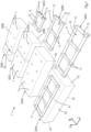
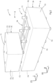
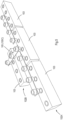
- Fig. 1 shows (parts of) an assembly 1 for constructing at least part of a wall 2, as indicated in Fig. 2 , from building blocks 3 and support blocks 5.
- the building blocks 3 and support blocks 5 are stacked in a vertical direction Z as alternating layers B, S, which themselves extend generally in horizontal directions X and Y.
- the wall 2 may have a length direction L and a width direction W in horizontal directions and a vertical height direction H.
- Each building block 3 comprises opposite pairs of faces F1 and F2; F3 and F4; and F5 and F6, respectively. Faces of at least one pair of opposite faces F1, F2; F3, F4; F5, F6; comprises a plurality of recesses 7 arranged spaced from each other in the respective face. As shown, the recesses may be blind holes defined by surrounding wall portions.
- the building blocks 3 may have various sizes as generally indicated with reference symbols 3A-3D in Fig. 1 .
- Each support block 5 comprises a body 9, and a plurality of protrusions 11 on opposite top and bottom sides of the body 9.
- the protrusions 11 are formed as substantially coaxial solid cylindrical rod portions of circular cross section, but other relative positions and shapes may be provided.
- the body 9 preferably is generally plane as shown here and may comprise one or more openings 10, providing the body 9 with a frame-like shape.
- the support blocks 5 may have various sizes as generally indicated with reference symbols 5A-5C in Fig. 1 . Note that the body 9 and some or all of the protrusions may be made of different materials like relatively soft polymeric material for the body 9 and one or more relatively hard materials for the protrusion 11, like glass- and/or metal-reinforced polymers.
- Each recess 7 of the plurality of recesses 7 comprises a recess support structure 8 inside the recess, e.g. a flat portion on an end face terminating the blind hole 7 (not visible in Figs. 1-2 ).
- Each protrusion 11 of the plurality of protrusion comprises a protrusion support structure, e.g. a flat end face 13 of the protrusion 11.
- the building blocks 3 and/or support bocks 5 may have various sizes as shown and generally indicated with reference symbols 3A-3D and, respectively, 5A-5D in Fig. 1 .
- the recesses 7 and protrusions 11 are arranged in a matching pattern, here a generally rectangular pattern, in particular square pattern.
- different patterns including triangular, hexagonal or other regular or irregular patterns may be provided.
- the recesses 7 and protrusions 11 are further formed such that the protrusions 11 are receivable in the recesses 7 to be accommodated and cooperate with each other to form the alternating layers of building blocks and support blocks stacked on top of each other such that the protrusions in one layer are accommodated in the recesses of the adjacent layer, and such that relative movement of the respective blocks in the W and L directions (X and Y directions) is restricted or prevented.
- the respective support structures 8, 13 engage each other and position and support the respective higher block 3 / 5, on the respective lower block 5 / 3 in each layer pair.
- the recesses 7 and protrusions 11 may be mated in the sense that the protrusions closely fit into the recesses with very little play in horizontal direction (XY), reducing tolerances in width and/or length directions of the wall.
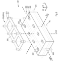
- Figs. 3 and 4 show another embodiment; an assembly 101 for constructing at least part of a wall 102, as indicated in Fig. 4 .
- the support blocks 105 are provided with protrusions 111 formed as hollow circular cylinders extending from a body 109; the annular top surfaces 113 of the protrusions form the protrusion support structures.
- the protrusions 111 are arranged in a single line pattern rather than in a distribution pattern in two directions W, L as before ( Figs. 1-2 ).
- the support blocks 105 may be used in combination with the building blocks 3, in particular two support blocks 105 being arranged adjacent each other (not shown), to fit and operably engage the recesses 7 of the building blocks 3 for stacking a wall.
- the building blocks 103 may be provided with annular recesses 107 comprising recess support structures 108, here optionally formed by bottom portions of the annular recess, see Fig. 4 .
- annular recesses may reduce the amount of material to be cut or otherwise removed from the building block relative to forming, like in Figs. 1-2 , a completely empty hole of equal extent (e.g. here: outer diameter) in the face.
- an annular structure may be formed, in particular: may be cut, more easily than a straight or angular recess, e.g. by hollow-core drilling.
- the size of the recess 107 and/or distribution of recesses 2, 102 in the face (F1, F2, etc) in a width direction W of the wall 2 or 102 may affect or even determine a lateral stability of the wall 2, 102.
- a remaining core 117 in an annular recess may convey an impression of strength and may actually provide strength to the wall as a hole by engaging and laterally supporting the cylindrical wall portion of a cylindrical support protrusion 111.
- a support block may at least partly be arranged so that at least some of its protrusions on one side are operably received in, and cooperate with, plural adjacent building blocks.
- the building blocks and support blocks interengage and interlock each other, defining relative positions and strength of the wall may be increased.
- constructing a wall by appropriately assembling the respective building blocks and support blocks is facilitated.
- a support block may be formed larger than a building block in at least one direction, e.g. being longer (L-direction) .
- any possible spaces 19, 119 between adjacent building blocks in a layer may be filled by additional material, which may take the form of a plate-like body and may have protrusions matching recesses in the associated faces F3, F4. Such body may be connectable with one or more support blocks 5, 105.
- additional material which may take the form of a plate-like body and may have protrusions matching recesses in the associated faces F3, F4.
- Such body may be connectable with one or more support blocks 5, 105.
- any interconnection, in particular fixation between adjacent layers of the same type (B-B, S-S) or of different type (B-S, S-B) may further strengthen the wall 2, 102.
- tolerances in spacing of building blocks 103 may be reduced. Attachment or fixation may be performed by any suitable means, like screws, bolts and nuts or threaded holes, etc.
- support blocks 5, 105 may be provided with locks like (series of) V-shaped recesses and/or serrations and/or other clamping mechanisms.
- ratchet-and-pawl-based binding strips a.k.a. "tie-wraps"
- the latter may be looped and/or may be integrated at least partly into the support blocks.
- a support block 105 may e.g. be arranged sideways perpendicular (in W-direction) to a length direction (L) of a building block 103 from one wall 102A to extend to an adjacent wall 102B and function as a wall anchor connecting both walls 102A, 120B, see Fig. 5 . This may obviate providing additional anchors and/or us of other materials.
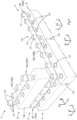
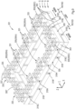
- Figs. 6-9 show a further embodiment; an assembly 301 comprising building blocks 303 and support blocks 305 (305A-305C) for constructing at least part of a wall 302, as indicated in Figs. 8-9 .
- the building blocks 303 are provided with recesses 307 having an elongated shape.
- the elongated recesses 307 have a relatively large size in a longitudinal direction 1 parallel to the length direction L of the building block 303, and a relatively small size in a transverse direction w parallel to the width direction W of the building block 303.
- the recesses 307 are cut into the building block 303 relative to references per direction L, W, H, determined as midplanes ML, MW, MH of the building block, e.g. determined with respect to an average of, respectively, the length, the width and the thickness of the building block.
- the midplanes ML, MW, MH cross in a centre lines CLW, CLH, CWH which in turn cross in a centre point C (not indicated) which may form a primary reference of the block 303.
- a reference point, line and/or plane may also be determined differently, e.g. relative to a particular feature of a building block, e.g. a marked, coated, sculpted or otherwise particularly treated side.
- each recess 307 of the plurality of recesses 307 comprises a recess support structure 308 inside the recess 307, e.g. a flat portion of a bottom 308 of the recess 307.
- Each protrusion 311 of the plurality of protrusions 311 comprises a protrusion support structure, e.g. a flat end face 313 of the protrusion 311.
- the protrusions 311 may be hollow as shown, e.g. to save material.
- the support blocks 305 may be similar or identical to the embodiment of Figs. 1-2 .
- the support blocks 305 may have various sizes as shown generally indicated with reference symbols 305A-305C in Fig. 6-9 .
- support blocks may be provided wherein the protrusions have a non-circular cross sectional shape, e.g. square, oblong rounded and/or otherwise elongated, the shape corresponding to the longitudinal direction of the elongated recesses. This may further fortify a wall built from the assembly.
- one or more of the protrusions may have profiled shape, e.g. ribbed shape, in cross section.
- protrusions could be formed as substantially X-shaped, Y-shaped, T-shaped, or star-shaped rods protruding from the body of the support block, as seen in top view.
- a wall may comprise a combination of building blocks according to plural embodiments, e.g. in particular according to Figs. 1-2 and Figs. 6-9 .
- the elongated recesses 307 of building blocks 303 may cooperate with the protrusions 311 of supporting blocks 305 connecting two adjacent building blocks 303. This may enable that, when assembled, the building blocks 302 may be arranged at different separations, providing a space 319 between facing faces (here: end faces F3, F4) of the building blocks 303 between a wide space 319 (top image); a small space 319B or even no space if and when the building blocks 302 can contact each other (centre image); or an intermediate width space 319C (bottom image).
- the maximum and minimum spaces may be determined by the relative sizes and positions of the recesses 307 and protrusions 311.
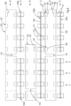
- Figs. 8 and 9 show that a support block 305 may at least partly be arranged so that at least some of its protrusions 311 on one side are operably received in, and cooperate with, plural adjacent building blocks 303.
- a support block 305B formed larger than a building block 303 in at least one direction e.g. being longer (L-direction), and/or see in Fig 9 : support block 305*.
- Fig. 8 further indicates that in a space 319 between two adjacent building blocks 319 a body 325 may be arranged, filling the space 319 at least partially in width and height directions (W, H).
- the bodies 325 are provided as open frame-like elements with optional hooks 327 for attachment to the bodies 309 of support blocks 305 and fixation of adjacent support block layers S-S.
- one or more of the bodies 325 may have a different shape and/or size (e.g. in the W and/or L direction), and/or may have a different construction such as being solid.
- One or more building blocks may be provided with grooves in side faces for accommodating at least part of such bodies 325 (not shown). This may, e.g., facilitate longitudinal adjustment of adjacent building blocks.
- Fig. 8 further shows use of a more traditionally shaped anchor 329 for attachment of the wall 302 to an adjacent wall (not shown), e.g. comprising a hook to engage (the body 309 of) a support portion 305; such anchor 329 may fit in a space 319 between adjacent building blocks 303.
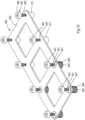
- Fig. 9 shows an exemplary generally rectangular wall construction with two long wall portions in X-direction and two short wall portions in Y -direction.
- the different building block layers B, B of the short wall portions will have the same size in Y -direction if the widths of the interstitial spaces 319D, 319E are sized correctly, and will only look pleasing if the widths are approximately equal; such equality may also improve strength of the wall portion.
- This also applies mutatis mutandis for (the spaces 319F, 319G, 319H of) the long wall portions in X-direction.
- the assembly 301 of building blocks 303 and support blocks 305 enables adjusting the relative positions of building blocks and therewith accommodate tolerances in them.
- Vertical spaces 320 are determined by interaction of the support structures (307, 308; 311, 313) of the building blocks 303 and support blocks 305.
- Fig. 9 further shows different embodiments of optional links 331 (331A, 331B) which may be comprised in the assembly 301.As may be seen from Fig. 9 , in order to determine the sizes of the walls 302 in the construction accurately, within a support block layer S adjacent support blocks 305 are connected together with support links 331 in length direction and support links 333 defining corner portions.
- the support links 331, 333 may have bodies 335 of the same or similar material and/or construction as the support blocks 305.
- the shown support links 331, 333 comprise holes 337 fitting a protrusion 311 of an adjacent support block 305.
- the sizes of support links 331, 333 in respective width directions match the sizes of (the protrusions of) the support blocks for proper interconnection.
- the sizes of support links 331 in respective length directions determine a separation of (protrusions 311 of) linked support blocks 305 and thus determine a length of a wall portion; the building blocks 303 coupled with the respective assembly of support blocks 305 and links 331, 331 may be arranged to provide a desired spacing, e.g. all spaces 319 being substantially equally wide. Note that in a joint of plural wall portions, such as in a corner, the separation and spacing (spaces 319) between building blocks may differ, which may be accommodated by appropriate selection of support link sizes when using substantially identical support blocks for each of the respective wall portions. Also, support links may accommodate a transition between one type of support block and another type.
- Differently sized support blocks and/or support links in particular with respect to the separation of protrusions may be colour coded for easy recognition. It is noted that the spaces 319, 320 may be at least partly filled with a mortar, a clay, a polymer, and/or another filler material, thus covering and obscuring support blocks 5, 105, 305, vertical bodies 325 and/or links 331, 333.
- the assembly may further comprise support blocks (not shown) having protrusions on only one side of the support block body, e.g. for forming a substantially flat base layer or top layer of support portions.
- a wall portion may be accurately sized by arranging a series of interconnected support portions (possibly using support links) on a base surface with the protrusions upward according to a predetermined size and/or pattern as support block layer S and a template for stacking thereon a first layer B of building blocks; positions of the building blocks being determined by the initial layer of support blocks.
- such one-sided support blocks may be used at openings in the wall e.g.
- relative positions of different layers may be arranged and/or checked by comparing relative positions of (e.g. alignment of) protrusions of support blocks rather than by comparing relative positions of building blocks; this obviates having to account for tolerances in and/or erratic shapes of building blocks.
- End space (19, 119, 319D, 319G) filler bodies may be provided with hooks engaging the bodies 9, 109 of support members 5, 105 of adjacent layers S, e.g. at or in openings of support members (e.g. openings 10, 110).
- the assembly may further comprise adjustment support blocks wherein one or more of the protrusions, preferably all protrusions, are size-adjustable, e.g. comprising complementary threaded portions.
- Fig. 10 shows a support block 405 wherein protrusions 411 on one side of the body 409 are provided as threaded objects, here bolts 441, fit into threaded holes 443.
- the support block 405 has no protrusions on that side so that the support block 405 may form a substantially flat base layer or top layer as described above.
- the bolt 441 provides the support structure of the thus-formed protrusion 411, in particular the top surface of the head 445.
- an external control portion e.g. a head 445 of the bolt 441 may be provided, e.g. one or more flat surfaces such as a hexagonal head enabling adjustment from aside relative to another object, e.g. a levelling rule.
- an adjustment support block may comprise a body having one or more threaded portions 447 through which a complementary threaded element 449 is fit to provide a protrusion providing a support structure 450 on one side of the body, wherein the element 449 itself is provided with an additional threaded portion for connecting an accordingly complementary threaded further element as a protrusion providing a support structure to the opposite side of the body; in Fig. 10 the additional threaded portion is formed as an internal threaded portion 451 and the further element as a matching bolt 441.
- adjustable protrusions may be provided with external threads onto which e.g. threaded nuts and/or threaded caps could be fit.
- Other adjustment portions could also be provided as protrusions.
- Size-adjustable protrusions allow establishing and/or correcting deviations from a default size, e.g. ascertaining a horizontal orientation of a building block layer B stacked on the adjustment support block and/or accommodating differently sized building blocks.
- (protrusions of) an at least partly single-sided support block for forming a substantially flat base layer may be adjustable to accommodate for a non-horizontal and/or uneven base surface.
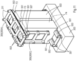
- Fig. 11 shows an embodiment wherein building blocks 503 are arranged standing, i.e. on a relatively short side, compared to other embodiments shown.
- Such standing orientation is particularly suited for ornamental portions of masonry and/or portions having a particular structural significance e.g. as typically found below and/or above windows, doors, etc.
- larger wall portions e.g. panels of multiple rows of building blocks or entire walls, may thus be realised.
- adjacent standing building blocks may be connected and/or aligned using any suitable support blocks as disclosed herein.
- adjustment support blocks e.g. 405 in Fig. 10
- the building blocks 503 in Fig. 11 are provided with optional additional recesses 551 formed in side faces F3, F4 in addition to the recesses 7, 107, 307 discussed above.
- additional recesses may be formed to match protrusions in adjacent support blocks, e.g. similar to and according to described details, options etc. of any one of the recesses discussed in this disclosure.
- the additional recesses 551 are formed as grooves, preferably formed into the building block 503 by cutting and/or with respect to one reference, e.g. a midplane ML (cf. Fig. 6 ).
- a position of the building block 503 may be free in the longitudinal direction of the groove relative to the positions of protrusions on the support blocks 505 if the latter are not without protrusions on the side of their body facing the standing building blocks 503.
- Spaces between protrusions of the support blocks may be at least partly filled up, e.g. forming ribs, and/or one or more caps 553 bridging spaces between adjacent protrusions may be provided, such fillings and/or caps 553 and the recesses (grooves 551) having matching sizes so that the latter can accommodate the former. This may increase freedom of positioning of the standing building blocks and/or increase support reliability for the standing blocks.
- the fillings and/or caps 553 and grooves 551 preferably provide matching support structures engaging each other and position and support the respective higher block (e.g. 503, 303) on the respective lower block (e.g. 303, 503) and relative movement of the respective blocks (e.g. 303, 503) in two mutually perpendicular directions generally parallel to the layers being restricted.
- support blocks may assist in determining a desired spacing of the standing building blocks and ensuring meeting tolerances, as discussed herein.
- Fig. 12 shows a method of manufacturing a building block, by example showing a building block according to Figs. 1-2 .
- the shown method is a method of post-processing.
- a building block a plurality of recesses is cut, here by drilling or milling all recesses together by a drilling apparatus 200 comprising plural opposite sets of drills 221.
- the building block is positioned and fixed.
- the building block may be clamped by clamping plates 223.
- the drill bits may be shaped to provide the recesses formed by them with a particular shape, e.g. having a varying diameter or being hollow for making annular recesses.
- all drills 221 are of the same type and/or shape, at least pairwise for opposite drills 221.
- the building block and/or the sets of drills 221 may be controllably moved with respect to each other for milling elongated recesses into the building block (cf. Figs. 6-9 ) rather than drilling cylindrical holes (cf. Figs. 1-2 ) and/or annular recesses (cf. Figs. 3-5 ) although annular recesses and/or other shapes could also be made by controlled relative movement of the building block and/or the sets of drills 221.
- At least some of the drills 221 may individually or collectively be checked and/or controlled regularly for position and/or wear so as to ensure proper forming of the recesses.
- Such position is determined for each drill and recess of/for opposite faces relative to a single common reference, irrespective of external properties of the building block regarding size, shape and/or surface structure.
- recesses in opposite sides are defined relative to one common reference instead of from both opposite sides independently. This prevents that (lack of) tolerances in the shape, size and/or structure of the building blocks extend into (lack of) the tolerances of the wall as a whole.
- stacking tolerances may be tightly controlled although the building blocks may have comparably rough and/or erratic shapes, structures, textures etc.
- the drills 221 may be similarly used for cutting grooves 551 in building blocks 503 shown in Fig. 11 .
- the apparatus 200 may comprise additional cutters for cutting grooves 551, and/or other cutters may be provided for such purpose.
- a support portion may comprise a pointed tip, e.g. a rib or a cone-shape which may be a truncated cone, and the recess may comprise a V-shaped structure like a conical bottom recess or a V-groove-shaped bottom. The latter may be in particular interesting for the embodiments largely according to Figs. 6-9 .
Landscapes
- Engineering & Computer Science (AREA)
- Architecture (AREA)
- Physics & Mathematics (AREA)
- Electromagnetism (AREA)
- Civil Engineering (AREA)
- Structural Engineering (AREA)
- Finishing Walls (AREA)
- Building Environments (AREA)
- Buildings Adapted To Withstand Abnormal External Influences (AREA)
Priority Applications (2)
| Application Number | Priority Date | Filing Date | Title |
|---|---|---|---|
| HRP20250175TT HRP20250175T1 (hr) | 2018-07-20 | 2019-07-22 | Zidni sklop |
| EP24222152.1A EP4509671A3 (de) | 2018-07-20 | 2019-07-22 | Wandaufbau |
Applications Claiming Priority (4)
| Application Number | Priority Date | Filing Date | Title |
|---|---|---|---|
| NL2021372A NL2021372B1 (en) | 2018-07-20 | 2018-07-20 | Wall assembly |
| NL2023037 | 2019-04-30 | ||
| PCT/NL2019/050504 WO2020017975A1 (en) | 2018-07-20 | 2019-07-22 | Wall assembly |
| EP19756009.7A EP3824149B1 (de) | 2018-07-20 | 2019-07-22 | Wandanordnung |
Related Parent Applications (1)
| Application Number | Title | Priority Date | Filing Date |
|---|---|---|---|
| EP19756009.7A Division EP3824149B1 (de) | 2018-07-20 | 2019-07-22 | Wandanordnung |
Related Child Applications (1)
| Application Number | Title | Priority Date | Filing Date |
|---|---|---|---|
| EP24222152.1A Division EP4509671A3 (de) | 2018-07-20 | 2019-07-22 | Wandaufbau |
Publications (3)
| Publication Number | Publication Date |
|---|---|
| EP4234829A2 true EP4234829A2 (de) | 2023-08-30 |
| EP4234829A3 EP4234829A3 (de) | 2023-10-11 |
| EP4234829B1 EP4234829B1 (de) | 2024-12-25 |
Family
ID=67667897
Family Applications (3)
| Application Number | Title | Priority Date | Filing Date |
|---|---|---|---|
| EP24222152.1A Pending EP4509671A3 (de) | 2018-07-20 | 2019-07-22 | Wandaufbau |
| EP19756009.7A Active EP3824149B1 (de) | 2018-07-20 | 2019-07-22 | Wandanordnung |
| EP23180296.8A Active EP4234829B1 (de) | 2018-07-20 | 2019-07-22 | Wandanordnung |
Family Applications Before (2)
| Application Number | Title | Priority Date | Filing Date |
|---|---|---|---|
| EP24222152.1A Pending EP4509671A3 (de) | 2018-07-20 | 2019-07-22 | Wandaufbau |
| EP19756009.7A Active EP3824149B1 (de) | 2018-07-20 | 2019-07-22 | Wandanordnung |
Country Status (9)
| Country | Link |
|---|---|
| US (2) | US12163329B2 (de) |
| EP (3) | EP4509671A3 (de) |
| DK (2) | DK3824149T3 (de) |
| ES (2) | ES3015002T3 (de) |
| HR (2) | HRP20231080T1 (de) |
| HU (2) | HUE064125T2 (de) |
| PL (2) | PL3824149T3 (de) |
| PT (2) | PT4234829T (de) |
| WO (1) | WO2020017975A1 (de) |
Citations (4)
| Publication number | Priority date | Publication date | Assignee | Title |
|---|---|---|---|---|
| US3390502A (en) | 1966-07-15 | 1968-07-02 | William E. Carroll | Brick and wall construction |
| DE8807645U1 (de) | 1988-05-11 | 1988-08-11 | Kasamentbau GmbH + Co KG, 2105 Seevetal | Wandbauelement |
| NL1015570C1 (nl) | 2000-06-29 | 2002-01-02 | Josephus Joannes N Lichtenberg | Methode voor het stapelen van een wand opgebouwd uit losse elementen, zoals baksteen. |
| NL1032906C2 (nl) | 2006-11-20 | 2008-05-21 | Crh Kleiwaren Beheer B V | Bouwelement. |
Family Cites Families (98)
| Publication number | Priority date | Publication date | Assignee | Title |
|---|---|---|---|---|
| US555693A (en) * | 1896-03-03 | Hubeetus geraerdts and willem geraerdts | ||
| US1355572A (en) * | 1918-06-03 | 1920-10-12 | Ross Herbert Ernest | Concrete building and concrete building construction |
| US1447827A (en) * | 1920-03-13 | 1923-03-06 | Paul D Warner | Wall construction |
| US1427372A (en) * | 1921-10-18 | 1922-08-29 | Geraerdts William | Fireproof wall |
| US1521430A (en) * | 1923-03-28 | 1924-12-30 | Scott E Campbell | Reenforced cement tile structure |
| US1665442A (en) * | 1925-06-20 | 1928-04-10 | Campbell Leon Jay | Building block |
| US2107144A (en) * | 1933-12-12 | 1938-02-01 | American Cyanamid & Chem Corp | Doweled slab |
| US2212184A (en) * | 1938-12-07 | 1940-08-20 | Angle W Powell | Building unit |
| US2303091A (en) * | 1939-09-11 | 1942-11-24 | Libbey Owens Ford Glass Co | Wall construction |
| US2684588A (en) * | 1950-11-22 | 1954-07-27 | Alan L Robertson | Plastic-filled masonry wall |
| US2683968A (en) * | 1952-10-28 | 1954-07-20 | Budd William | Sea wall |
| US2971295A (en) * | 1955-03-21 | 1961-02-14 | Phillips Petroleum Co | Prestressed concrete units and structures |
| US3076286A (en) * | 1955-07-15 | 1963-02-05 | Stephen J Czecholinski | Building blocks |
| US3295286A (en) * | 1961-05-31 | 1967-01-03 | Owens Illinois Inc | Cementitious slab with bolt means |
| US3296758A (en) * | 1963-06-28 | 1967-01-10 | Kirkkejner O Knudsen | Superimposed building blocks with vertically spaced flat bars interfitted therewith connected by threaded stud members |
| FR1387024A (fr) * | 1963-07-09 | 1965-01-29 | Maçonneries de briques creuses écornées agrafées | |
| US3374589A (en) * | 1965-10-12 | 1968-03-26 | Fred Neal Jr. | Course spacer and mortar barrier |
| FR1476209A (fr) * | 1966-04-15 | 1967-04-07 | Perfectionnements apportés aux structures verticales pour constructions | |
| US3429092A (en) * | 1966-05-26 | 1969-02-25 | Dyna Structures | Structural frames and methods and means therefor |
| US3430404A (en) * | 1967-03-20 | 1969-03-04 | George B Muse | Apertured wall construction |
| US3537687A (en) * | 1967-09-25 | 1970-11-03 | Philip Adelman | Garden fence and wall |
| GB1188624A (en) * | 1967-09-26 | 1970-04-22 | Rupert George Steed | Improvements in or relating to Wall Construction |
| US3478482A (en) * | 1967-10-24 | 1969-11-18 | Richard L Weir | Building block construction |
| US3511000A (en) * | 1968-08-08 | 1970-05-12 | Henry P C Keuls | Interlocking hollow building blocks |
| FR2055983A5 (de) * | 1969-08-14 | 1971-05-14 | Vidal Henri | |
| US3759003A (en) * | 1971-12-23 | 1973-09-18 | J Wilson | Pinned joint |
| GB2065740A (en) * | 1979-12-07 | 1981-07-01 | Fletcher Timber Ltd | Modular building system and components therefor |
| GB1559636A (en) * | 1976-07-05 | 1980-01-23 | Baupres Ag | Building block |
| US4107894A (en) * | 1976-10-29 | 1978-08-22 | Mullins Wayne L | Interlocking cementitious building blocks |
| DE2651182A1 (de) * | 1976-11-10 | 1978-05-18 | Geb Jordan Kriemhild Schlomann | Mauerverbund mit formschluessigen verbindungen |
| US4067165A (en) * | 1976-11-19 | 1978-01-10 | Hiebert, Inc. | Panel system |
| CA1083846A (en) * | 1977-12-01 | 1980-08-19 | Cecil Kanigan | Block or brick laying guide reinforcing module |
| FR2552472B2 (fr) * | 1983-02-08 | 1985-11-08 | Ott Renaud | Systeme constructif utilisant des coffrages perdus notamment isolants et armes |
| CH659101A5 (de) * | 1982-12-01 | 1986-12-31 | Anton Erb | Schubduebel. |
| DE3310370C2 (de) * | 1983-01-17 | 1985-02-28 | Poschinger-Camphausen, Florian von, 8110 Murnau | Winkelig, vorzugsweise rechtwinkelig, miteinander verbundene Wandungen o.dgl. übereinstimmender Breite |
| GB2169932A (en) * | 1985-01-17 | 1986-07-23 | Martin Rigby | Spacing bricks |
| GB8712171D0 (en) * | 1987-05-22 | 1987-06-24 | Marler Haley Expostems Ltd | Display frame |
| GB2215749A (en) * | 1988-03-11 | 1989-09-27 | John Heelan | Apertured building blocks with locating pegs |
| US4975008A (en) * | 1989-03-31 | 1990-12-04 | Illinois Tool Works, Inc. | Fastener assembly with sealing grommet |
| US5240343A (en) * | 1989-12-12 | 1993-08-31 | Snap Edge Corporation | Holding device for paving blocks |
| KR920004733Y1 (ko) * | 1990-06-09 | 1992-07-18 | 김성호 | 장식대용 조립식 블럭 |
| CA2045953C (en) * | 1991-06-28 | 1995-12-19 | Angelo Risi | Connector for use in combination with blocks for wall structures or the like |
| IT1257727B (it) * | 1992-11-03 | 1996-02-13 | Struttura di mattonella, particolarmente per l'edilizia | |
| US5694997A (en) * | 1993-05-05 | 1997-12-09 | Styger; John Errol | Gravity exhibition stand |
| US5560167A (en) * | 1994-05-25 | 1996-10-01 | Miceli; Robert | Laminated masonry block system |
| DE29503220U1 (de) * | 1995-02-25 | 1995-06-01 | Zecherle, Hubert, Dipl.-Ing. (FH), 82205 Gilching | Mittel zur mörtelfreien Verbindung von Mauersteinen (Mauer-Stick- Mauer-3-Stick, Stickband/Leiste) |
| DE59500348D1 (de) * | 1995-04-13 | 1997-08-07 | Dotin B V | Bauelement |
| US5881515A (en) * | 1995-10-23 | 1999-03-16 | George; Mark D. | Concatenated structures of modular members |
| US5729948A (en) * | 1996-08-29 | 1998-03-24 | Levy; Tzadok | Apparatus and method for rigidly joining construction elements to one another |
| CA2220743C (en) * | 1997-11-19 | 2000-10-24 | David W. Fielding | Drywall construction method and means therefor |
| US6000186A (en) | 1996-12-05 | 1999-12-14 | Fielding; David W. | Drywall construction and means therefor |
| US5890332A (en) * | 1997-01-17 | 1999-04-06 | Skidmore; Lester J. | Reconstituted wood block modular building system |
| US5829217A (en) * | 1997-01-21 | 1998-11-03 | Colen; William J. | Wall construction and spacer for use therewith |
| US5934037A (en) * | 1997-12-22 | 1999-08-10 | Bundra; Octavian | Building block |
| US6266934B1 (en) * | 1999-04-09 | 2001-07-31 | Blh, Inc | Supports for log structures |
| CA2284194A1 (en) * | 1999-09-14 | 2001-03-14 | Bud T.J. Johnson | Mortarless bolt-down building blocks |
| DE10033481A1 (de) * | 2000-07-10 | 2002-01-24 | Weinert Thomas | Zwangsgeführter Stein mit Rundkanal Vertikal |
| GB0026290D0 (en) * | 2000-10-27 | 2000-12-13 | Herbison Francis D | Spacer element |
| US6585028B2 (en) * | 2001-06-29 | 2003-07-01 | Richard Verdicchio | Modular wall system |
| US6571525B2 (en) * | 2001-08-01 | 2003-06-03 | J. David Coleman | Construction block |
| GB0216455D0 (en) * | 2002-07-16 | 2002-08-21 | Patchell Brendan | Building system |
| US7117647B2 (en) * | 2003-02-26 | 2006-10-10 | Pointblank Design Inc. | System for constructing log structures |
| CN100335726C (zh) * | 2003-03-06 | 2007-09-05 | 独立行政法人科学技术振兴机构 | 建筑物的墙体结构 |
| US6991397B2 (en) * | 2003-11-07 | 2006-01-31 | Modular Systems, Inc. | Dowel fastener and joints including same |
| WO2005100712A2 (en) * | 2004-04-13 | 2005-10-27 | Shaw Reece F | Article of manufacture for building structures made from precast concrete units and process for making structural system |
| US7815391B2 (en) * | 2004-07-23 | 2010-10-19 | Kauppila Richard W | Structural member joints |
| CA2496066C (en) * | 2005-02-04 | 2012-05-29 | Jean-Robert Tremblay | Method and implements for erecting walls including a plurality of wall components |
| US20060185300A1 (en) * | 2005-02-07 | 2006-08-24 | Jean-Robert Tremblay | Method and implements for erecting walls including a plurality of wall components |
| CA2596472A1 (en) * | 2005-02-10 | 2006-08-17 | Westblock Systems, Inc. | Masonry block wall system |
| DE102005039767B4 (de) * | 2005-08-23 | 2012-06-21 | Airbus Operations Gmbh | Schalldämmelement für Verkehrsmittel, insbesondere für Luftfahrzeuge |
| SE528812C2 (sv) * | 2005-08-30 | 2007-02-20 | Staffan Schager | Byggnadselement av trä |
| US7503730B2 (en) * | 2006-02-01 | 2009-03-17 | Mortarless Technologies, Llc | Modular block wall system |
| US9206597B2 (en) * | 2006-02-13 | 2015-12-08 | 3B Construction Solutions, Inc. | Unitized post tension block system for masonry structures |
| JP4903860B2 (ja) * | 2006-05-15 | 2012-03-28 | 盧貞吟 | 組立て式仕切り構造 |
| ATE479481T1 (de) * | 2007-02-01 | 2010-09-15 | Robosynthesis Ltd | Baukasten |
| FR2912163A1 (fr) * | 2007-02-02 | 2008-08-08 | Laurent Antoine Velardo | Bloc alveole permettant la construction de tout type de mur en maconnerie traditionnel |
| US7975444B2 (en) * | 2007-11-29 | 2011-07-12 | Barsplice Products, Inc. | Coupler system for adjacent precast concrete members and method of connecting |
| WO2010100534A2 (en) * | 2009-03-04 | 2010-09-10 | Nico Rogai | Stackable joint module for buildings |
| US8082710B2 (en) * | 2009-08-21 | 2011-12-27 | Ballistics Technology International Ltd. | Removable attachment system for buildings |
| US8176697B1 (en) * | 2009-09-01 | 2012-05-15 | Bolander Ii Larry J | Building block |
| WO2012012455A2 (en) * | 2010-07-19 | 2012-01-26 | Kramer Richard H | Prefabricated building and kit |
| EP2569065B1 (de) * | 2011-01-31 | 2016-11-16 | Value Chain Network (Hong Kong) Limited | Gebäudeblöcke und befestigungselemente für gebäudeblöcke |
| US8898990B2 (en) * | 2011-05-27 | 2014-12-02 | Coobs Canada Ltd. | Modular building blocks with interlocking reinforcement rods |
| WO2012162834A1 (en) * | 2011-05-31 | 2012-12-06 | Maeers Richard | Construction blocks |
| US20140106108A1 (en) * | 2011-06-10 | 2014-04-17 | Tsz Chung Lin | Building blocks |
| ES2415982B1 (es) * | 2011-12-26 | 2014-05-27 | Joaquin Angel Ros Aroca | Cerramiento ligero ensamblado, de alto aislamiento térmico y ácustico, realizado con bloques de hormigón con áridos de vidrio triturado reciclado. |
| BE1020597A3 (nl) * | 2012-03-30 | 2014-01-07 | Vandenbempt Patent | Snelbouwsteen, evenals kunststof inzetstuk voor het vervaardigen van zulke snelbouwsteen. |
| ITTO20121042A1 (it) * | 2012-12-04 | 2014-06-05 | Flavio Lanese | Modulo riutilizzabile per la realizzazione di almeno una porzione di una parete smontabile di una costruzione |
| WO2015132422A1 (es) * | 2014-03-06 | 2015-09-11 | Industrias Audiolis, S.L. | Placa constructiva, sistema constructivo antisísmico y metodo de construccion |
| GB2528090A (en) * | 2014-07-09 | 2016-01-13 | Brian Robert Alfred Wybrow | Building system |
| WO2016054187A1 (en) * | 2014-09-30 | 2016-04-07 | Miller Philip Glen | Self-bracing, two-way moment frame precast system for industrial support structure and method of utilizing same |
| DE102014115808A1 (de) * | 2014-10-30 | 2016-05-04 | Arthur Neuske | Quaderförmiges Bauelement |
| US10106980B2 (en) * | 2016-04-16 | 2018-10-23 | Lazaro A. Martinez | Block interlocking module and system to build architectural structures |
| EP3445924B1 (de) | 2016-04-18 | 2023-12-20 | B&D Opmeer B.V. | Verfahren zur errichtung eines gebaüdes mit trockenen mauern |
| US10202755B2 (en) * | 2016-10-06 | 2019-02-12 | Technologie 2000 Inc. | Construction block anchoring system |
| US10273683B2 (en) * | 2016-10-17 | 2019-04-30 | Vaughn Fryfogle | Blocks and molds for building landscape walls and methods of making the blocks |
| CA2970210A1 (en) * | 2017-06-09 | 2018-12-09 | Inscape Corporation | Connector for lightweight office partition |
| US10617969B2 (en) * | 2017-07-25 | 2020-04-14 | BJ Trading LLC | Toy building blocks set and cooperating screws |
-
2019
- 2019-07-22 US US17/261,779 patent/US12163329B2/en active Active
- 2019-07-22 HR HRP20231080TT patent/HRP20231080T1/hr unknown
- 2019-07-22 EP EP24222152.1A patent/EP4509671A3/de active Pending
- 2019-07-22 HR HRP20250175TT patent/HRP20250175T1/hr unknown
- 2019-07-22 EP EP19756009.7A patent/EP3824149B1/de active Active
- 2019-07-22 ES ES23180296T patent/ES3015002T3/es active Active
- 2019-07-22 PT PT231802968T patent/PT4234829T/pt unknown
- 2019-07-22 HU HUE19756009A patent/HUE064125T2/hu unknown
- 2019-07-22 EP EP23180296.8A patent/EP4234829B1/de active Active
- 2019-07-22 PT PT197560097T patent/PT3824149T/pt unknown
- 2019-07-22 PL PL19756009.7T patent/PL3824149T3/pl unknown
- 2019-07-22 PL PL23180296.8T patent/PL4234829T3/pl unknown
- 2019-07-22 DK DK19756009.7T patent/DK3824149T3/da active
- 2019-07-22 HU HUE23180296A patent/HUE070420T2/hu unknown
- 2019-07-22 WO PCT/NL2019/050504 patent/WO2020017975A1/en not_active Ceased
- 2019-07-22 ES ES19756009T patent/ES2955401T3/es active Active
- 2019-07-22 DK DK23180296.8T patent/DK4234829T3/da active
-
2024
- 2024-11-25 US US18/958,494 patent/US20250084636A1/en active Pending
Patent Citations (4)
| Publication number | Priority date | Publication date | Assignee | Title |
|---|---|---|---|---|
| US3390502A (en) | 1966-07-15 | 1968-07-02 | William E. Carroll | Brick and wall construction |
| DE8807645U1 (de) | 1988-05-11 | 1988-08-11 | Kasamentbau GmbH + Co KG, 2105 Seevetal | Wandbauelement |
| NL1015570C1 (nl) | 2000-06-29 | 2002-01-02 | Josephus Joannes N Lichtenberg | Methode voor het stapelen van een wand opgebouwd uit losse elementen, zoals baksteen. |
| NL1032906C2 (nl) | 2006-11-20 | 2008-05-21 | Crh Kleiwaren Beheer B V | Bouwelement. |
Also Published As
| Publication number | Publication date |
|---|---|
| EP4234829B1 (de) | 2024-12-25 |
| DK3824149T3 (da) | 2023-09-18 |
| HUE070420T2 (hu) | 2025-06-28 |
| US20250084636A1 (en) | 2025-03-13 |
| HRP20231080T1 (hr) | 2024-01-05 |
| EP4509671A3 (de) | 2025-04-09 |
| US20210293018A1 (en) | 2021-09-23 |
| DK4234829T3 (da) | 2025-03-03 |
| US12163329B2 (en) | 2024-12-10 |
| EP4234829A3 (de) | 2023-10-11 |
| PL3824149T3 (pl) | 2024-02-19 |
| WO2020017975A1 (en) | 2020-01-23 |
| ES3015002T3 (en) | 2025-04-28 |
| EP4509671A2 (de) | 2025-02-19 |
| EP3824149A1 (de) | 2021-05-26 |
| PT4234829T (pt) | 2025-03-13 |
| PL4234829T3 (pl) | 2025-05-26 |
| EP3824149B1 (de) | 2023-06-21 |
| HRP20250175T1 (hr) | 2025-04-11 |
| ES2955401T3 (es) | 2023-11-30 |
| HUE064125T2 (hu) | 2024-02-28 |
| PT3824149T (pt) | 2023-09-14 |
Similar Documents
| Publication | Publication Date | Title |
|---|---|---|
| US6488448B1 (en) | Block module | |
| US10760281B2 (en) | Veneer connectors, wall blocks, veneer panels for wall blocks, and walls | |
| US4514949A (en) | Interlocking system for building walls | |
| US6962028B2 (en) | Interlocking masonry articles and methods thereof | |
| KR920002872B1 (ko) | 유리블럭패널과그구성방법및이에사용되는연결구 | |
| EP3347529B1 (de) | Bausystem mit kernstützklötze und dekorativen attikablöcken | |
| US8171693B2 (en) | Interlocking masonry blocks | |
| EP3445924B1 (de) | Verfahren zur errichtung eines gebaüdes mit trockenen mauern | |
| EP4234829B1 (de) | Wandanordnung | |
| CN210086885U (zh) | 一种镂空墙体加固结构 | |
| KR101779878B1 (ko) | 조립식 벽돌 건식 시공구조 및 시공방법 | |
| NL2024707B1 (en) | Wall assembly | |
| NL2021372B1 (en) | Wall assembly | |
| CA2516866A1 (en) | Shim having through openings | |
| CN220954032U (zh) | 一种空心砖墙体结构 | |
| CN113775133B (zh) | 一种酒店设计用墙面铺装结构 | |
| CN119373257B (zh) | 一种装饰砌筑墙体及其施工方法 | |
| CN219080683U (zh) | 适于串挂安装的陶土砖 | |
| KR200389562Y1 (ko) | 모르타르레스 중공 콘크리트 블록 | |
| CA2313062C (en) | Modular segmented retaining wall | |
| CA2488586A1 (en) | Brick kit | |
| KR20000016300U (ko) | 건축용 조립식 블록 | |
| WO2005108703A1 (en) | Construction module of tiles | |
| MX2014008596A (es) | Sistema de construccion mediante bloques ensambles. |
Legal Events
| Date | Code | Title | Description |
|---|---|---|---|
| REG | Reference to a national code |
Ref country code: HR Ref legal event code: TUEP Ref document number: P20250175T Country of ref document: HR |
|
| PUAI | Public reference made under article 153(3) epc to a published international application that has entered the european phase |
Free format text: ORIGINAL CODE: 0009012 |
|
| STAA | Information on the status of an ep patent application or granted ep patent |
Free format text: STATUS: THE APPLICATION HAS BEEN PUBLISHED |
|
| AC | Divisional application: reference to earlier application |
Ref document number: 3824149 Country of ref document: EP Kind code of ref document: P |
|
| AK | Designated contracting states |
Kind code of ref document: A2 Designated state(s): AL AT BE BG CH CY CZ DE DK EE ES FI FR GB GR HR HU IE IS IT LI LT LU LV MC MK MT NL NO PL PT RO RS SE SI SK SM TR |
|
| PUAL | Search report despatched |
Free format text: ORIGINAL CODE: 0009013 |
|
| AK | Designated contracting states |
Kind code of ref document: A3 Designated state(s): AL AT BE BG CH CY CZ DE DK EE ES FI FR GB GR HR HU IE IS IT LI LT LU LV MC MK MT NL NO PL PT RO RS SE SI SK SM TR |
|
| RIC1 | Information provided on ipc code assigned before grant |
Ipc: E04B 2/02 20060101ALI20230905BHEP Ipc: E04B 2/08 20060101AFI20230905BHEP |
|
| STAA | Information on the status of an ep patent application or granted ep patent |
Free format text: STATUS: REQUEST FOR EXAMINATION WAS MADE |
|
| 17P | Request for examination filed |
Effective date: 20240411 |
|
| RBV | Designated contracting states (corrected) |
Designated state(s): AL AT BE BG CH CY CZ DE DK EE ES FI FR GB GR HR HU IE IS IT LI LT LU LV MC MK MT NL NO PL PT RO RS SE SI SK SM TR |
|
| GRAP | Despatch of communication of intention to grant a patent |
Free format text: ORIGINAL CODE: EPIDOSNIGR1 |
|
| STAA | Information on the status of an ep patent application or granted ep patent |
Free format text: STATUS: GRANT OF PATENT IS INTENDED |
|
| INTG | Intention to grant announced |
Effective date: 20240719 |
|
| GRAS | Grant fee paid |
Free format text: ORIGINAL CODE: EPIDOSNIGR3 |
|
| GRAA | (expected) grant |
Free format text: ORIGINAL CODE: 0009210 |
|
| STAA | Information on the status of an ep patent application or granted ep patent |
Free format text: STATUS: THE PATENT HAS BEEN GRANTED |
|
| AC | Divisional application: reference to earlier application |
Ref document number: 3824149 Country of ref document: EP Kind code of ref document: P |
|
| AK | Designated contracting states |
Kind code of ref document: B1 Designated state(s): AL AT BE BG CH CY CZ DE DK EE ES FI FR GB GR HR HU IE IS IT LI LT LU LV MC MK MT NL NO PL PT RO RS SE SI SK SM TR |
|
| REG | Reference to a national code |
Ref country code: GB Ref legal event code: FG4D |
|
| REG | Reference to a national code |
Ref country code: CH Ref legal event code: EP |
|
| REG | Reference to a national code |
Ref country code: DE Ref legal event code: R096 Ref document number: 602019064136 Country of ref document: DE |
|
| REG | Reference to a national code |
Ref country code: IE Ref legal event code: FG4D |
|
| REG | Reference to a national code |
Ref country code: SE Ref legal event code: TRGR |
|
| REG | Reference to a national code |
Ref country code: DK Ref legal event code: T3 Effective date: 20250224 |
|
| REG | Reference to a national code |
Ref country code: PT Ref legal event code: SC4A Ref document number: 4234829 Country of ref document: PT Date of ref document: 20250313 Kind code of ref document: T Free format text: AVAILABILITY OF NATIONAL TRANSLATION Effective date: 20250307 |
|
| REG | Reference to a national code |
Ref country code: NL Ref legal event code: FP |
|
| REG | Reference to a national code |
Ref country code: LT Ref legal event code: MG9D |
|
| REG | Reference to a national code |
Ref country code: HR Ref legal event code: T1PR Ref document number: P20250175 Country of ref document: HR |
|
| PG25 | Lapsed in a contracting state [announced via postgrant information from national office to epo] |
Ref country code: FI Free format text: LAPSE BECAUSE OF FAILURE TO SUBMIT A TRANSLATION OF THE DESCRIPTION OR TO PAY THE FEE WITHIN THE PRESCRIBED TIME-LIMIT Effective date: 20241225 |
|
| PG25 | Lapsed in a contracting state [announced via postgrant information from national office to epo] |
Ref country code: BG Free format text: LAPSE BECAUSE OF FAILURE TO SUBMIT A TRANSLATION OF THE DESCRIPTION OR TO PAY THE FEE WITHIN THE PRESCRIBED TIME-LIMIT Effective date: 20241225 |
|
| PG25 | Lapsed in a contracting state [announced via postgrant information from national office to epo] |
Ref country code: NO Free format text: LAPSE BECAUSE OF FAILURE TO SUBMIT A TRANSLATION OF THE DESCRIPTION OR TO PAY THE FEE WITHIN THE PRESCRIBED TIME-LIMIT Effective date: 20250325 |
|
| PG25 | Lapsed in a contracting state [announced via postgrant information from national office to epo] |
Ref country code: LV Free format text: LAPSE BECAUSE OF FAILURE TO SUBMIT A TRANSLATION OF THE DESCRIPTION OR TO PAY THE FEE WITHIN THE PRESCRIBED TIME-LIMIT Effective date: 20241225 Ref country code: GR Free format text: LAPSE BECAUSE OF FAILURE TO SUBMIT A TRANSLATION OF THE DESCRIPTION OR TO PAY THE FEE WITHIN THE PRESCRIBED TIME-LIMIT Effective date: 20250326 |
|
| PG25 | Lapsed in a contracting state [announced via postgrant information from national office to epo] |
Ref country code: RS Free format text: LAPSE BECAUSE OF FAILURE TO SUBMIT A TRANSLATION OF THE DESCRIPTION OR TO PAY THE FEE WITHIN THE PRESCRIBED TIME-LIMIT Effective date: 20250325 |
|
| REG | Reference to a national code |
Ref country code: HU Ref legal event code: AG4A Ref document number: E070420 Country of ref document: HU |
|
| PG25 | Lapsed in a contracting state [announced via postgrant information from national office to epo] |
Ref country code: SM Free format text: LAPSE BECAUSE OF FAILURE TO SUBMIT A TRANSLATION OF THE DESCRIPTION OR TO PAY THE FEE WITHIN THE PRESCRIBED TIME-LIMIT Effective date: 20241225 |
|
| PG25 | Lapsed in a contracting state [announced via postgrant information from national office to epo] |
Ref country code: IS Free format text: LAPSE BECAUSE OF FAILURE TO SUBMIT A TRANSLATION OF THE DESCRIPTION OR TO PAY THE FEE WITHIN THE PRESCRIBED TIME-LIMIT Effective date: 20250425 |
|
| PG25 | Lapsed in a contracting state [announced via postgrant information from national office to epo] |
Ref country code: EE Free format text: LAPSE BECAUSE OF FAILURE TO SUBMIT A TRANSLATION OF THE DESCRIPTION OR TO PAY THE FEE WITHIN THE PRESCRIBED TIME-LIMIT Effective date: 20241225 |
|
| PG25 | Lapsed in a contracting state [announced via postgrant information from national office to epo] |
Ref country code: RO Free format text: LAPSE BECAUSE OF FAILURE TO SUBMIT A TRANSLATION OF THE DESCRIPTION OR TO PAY THE FEE WITHIN THE PRESCRIBED TIME-LIMIT Effective date: 20241225 |
|
| PG25 | Lapsed in a contracting state [announced via postgrant information from national office to epo] |
Ref country code: SK Free format text: LAPSE BECAUSE OF FAILURE TO SUBMIT A TRANSLATION OF THE DESCRIPTION OR TO PAY THE FEE WITHIN THE PRESCRIBED TIME-LIMIT Effective date: 20241225 |
|
| PG25 | Lapsed in a contracting state [announced via postgrant information from national office to epo] |
Ref country code: CZ Free format text: LAPSE BECAUSE OF FAILURE TO SUBMIT A TRANSLATION OF THE DESCRIPTION OR TO PAY THE FEE WITHIN THE PRESCRIBED TIME-LIMIT Effective date: 20241225 |
|
| PG25 | Lapsed in a contracting state [announced via postgrant information from national office to epo] |
Ref country code: IT Free format text: LAPSE BECAUSE OF FAILURE TO SUBMIT A TRANSLATION OF THE DESCRIPTION OR TO PAY THE FEE WITHIN THE PRESCRIBED TIME-LIMIT Effective date: 20241225 |
|
| PGFP | Annual fee paid to national office [announced via postgrant information from national office to epo] |
Ref country code: HU Payment date: 20250704 Year of fee payment: 7 |
|
| REG | Reference to a national code |
Ref country code: HR Ref legal event code: ODRP Ref document number: P20250175 Country of ref document: HR Payment date: 20250718 Year of fee payment: 7 |
|
| PGFP | Annual fee paid to national office [announced via postgrant information from national office to epo] |
Ref country code: NL Payment date: 20250726 Year of fee payment: 7 Ref country code: LU Payment date: 20250728 Year of fee payment: 7 |
|
| REG | Reference to a national code |
Ref country code: DE Ref legal event code: R097 Ref document number: 602019064136 Country of ref document: DE |
|
| PGFP | Annual fee paid to national office [announced via postgrant information from national office to epo] |
Ref country code: PT Payment date: 20250702 Year of fee payment: 7 Ref country code: ES Payment date: 20250801 Year of fee payment: 7 |
|
| PGFP | Annual fee paid to national office [announced via postgrant information from national office to epo] |
Ref country code: DK Payment date: 20250725 Year of fee payment: 7 Ref country code: DE Payment date: 20250729 Year of fee payment: 7 |
|
| PGFP | Annual fee paid to national office [announced via postgrant information from national office to epo] |
Ref country code: TR Payment date: 20250711 Year of fee payment: 7 Ref country code: PL Payment date: 20250703 Year of fee payment: 7 |
|
| PGFP | Annual fee paid to national office [announced via postgrant information from national office to epo] |
Ref country code: BE Payment date: 20250728 Year of fee payment: 7 Ref country code: GB Payment date: 20250728 Year of fee payment: 7 |
|
| PGFP | Annual fee paid to national office [announced via postgrant information from national office to epo] |
Ref country code: HR Payment date: 20250718 Year of fee payment: 7 |
|
| PGFP | Annual fee paid to national office [announced via postgrant information from national office to epo] |
Ref country code: FR Payment date: 20250725 Year of fee payment: 7 Ref country code: AT Payment date: 20250702 Year of fee payment: 7 |
|
| PGFP | Annual fee paid to national office [announced via postgrant information from national office to epo] |
Ref country code: CH Payment date: 20250801 Year of fee payment: 7 Ref country code: SE Payment date: 20250727 Year of fee payment: 7 |
|
| PGFP | Annual fee paid to national office [announced via postgrant information from national office to epo] |
Ref country code: IE Payment date: 20250728 Year of fee payment: 7 |
|
| PLBE | No opposition filed within time limit |
Free format text: ORIGINAL CODE: 0009261 |
|
| STAA | Information on the status of an ep patent application or granted ep patent |
Free format text: STATUS: NO OPPOSITION FILED WITHIN TIME LIMIT |
|
| 26N | No opposition filed |
Effective date: 20250926 |