EP4234499A1 - Ternärer vorläufer und herstellungsverfahren dafür, ternäres positivelektrodenmaterial und elektrische vorrichtung - Google Patents
Ternärer vorläufer und herstellungsverfahren dafür, ternäres positivelektrodenmaterial und elektrische vorrichtung Download PDFInfo
- Publication number
- EP4234499A1 EP4234499A1 EP22868735.6A EP22868735A EP4234499A1 EP 4234499 A1 EP4234499 A1 EP 4234499A1 EP 22868735 A EP22868735 A EP 22868735A EP 4234499 A1 EP4234499 A1 EP 4234499A1
- Authority
- EP
- European Patent Office
- Prior art keywords
- ternary precursor
- ternary
- positive electrode
- precursor
- electrode material
- Prior art date
- Legal status (The legal status is an assumption and is not a legal conclusion. Google has not performed a legal analysis and makes no representation as to the accuracy of the status listed.)
- Pending
Links
- 239000002243 precursor Substances 0.000 title claims abstract description 250
- 239000007774 positive electrode material Substances 0.000 title claims abstract description 107
- 238000002360 preparation method Methods 0.000 title claims abstract description 58
- 239000013078 crystal Substances 0.000 claims abstract description 56
- 238000002441 X-ray diffraction Methods 0.000 claims abstract description 23
- 239000011164 primary particle Substances 0.000 claims abstract description 16
- QGZKDVFQNNGYKY-UHFFFAOYSA-N Ammonia Chemical compound N QGZKDVFQNNGYKY-UHFFFAOYSA-N 0.000 claims description 137
- 239000002245 particle Substances 0.000 claims description 83
- PXHVJJICTQNCMI-UHFFFAOYSA-N nickel Substances [Ni] PXHVJJICTQNCMI-UHFFFAOYSA-N 0.000 claims description 80
- 229910021529 ammonia Inorganic materials 0.000 claims description 67
- 239000011572 manganese Substances 0.000 claims description 48
- 239000000243 solution Substances 0.000 claims description 44
- 229910052751 metal Inorganic materials 0.000 claims description 41
- 239000002184 metal Substances 0.000 claims description 41
- 238000000034 method Methods 0.000 claims description 38
- KFDQGLPGKXUTMZ-UHFFFAOYSA-N [Mn].[Co].[Ni] Chemical compound [Mn].[Co].[Ni] KFDQGLPGKXUTMZ-UHFFFAOYSA-N 0.000 claims description 35
- 239000012266 salt solution Substances 0.000 claims description 35
- 239000002002 slurry Substances 0.000 claims description 27
- 229910052759 nickel Inorganic materials 0.000 claims description 25
- 239000002585 base Substances 0.000 claims description 21
- 230000006835 compression Effects 0.000 claims description 21
- 238000007906 compression Methods 0.000 claims description 21
- 238000009826 distribution Methods 0.000 claims description 21
- 229910052748 manganese Inorganic materials 0.000 claims description 18
- 238000005336 cracking Methods 0.000 claims description 17
- PWHULOQIROXLJO-UHFFFAOYSA-N Manganese Chemical compound [Mn] PWHULOQIROXLJO-UHFFFAOYSA-N 0.000 claims description 16
- 229910017052 cobalt Inorganic materials 0.000 claims description 16
- 239000010941 cobalt Substances 0.000 claims description 16
- GUTLYIVDDKVIGB-UHFFFAOYSA-N cobalt atom Chemical compound [Co] GUTLYIVDDKVIGB-UHFFFAOYSA-N 0.000 claims description 16
- XLYOFNOQVPJJNP-UHFFFAOYSA-N water Substances O XLYOFNOQVPJJNP-UHFFFAOYSA-N 0.000 claims description 16
- 229910052782 aluminium Inorganic materials 0.000 claims description 11
- 230000001186 cumulative effect Effects 0.000 claims description 9
- 239000007788 liquid Substances 0.000 claims description 8
- 229910052719 titanium Inorganic materials 0.000 claims description 8
- 239000003513 alkali Substances 0.000 claims description 7
- 229910052726 zirconium Inorganic materials 0.000 claims description 7
- 239000011163 secondary particle Substances 0.000 claims description 6
- 229910052712 strontium Inorganic materials 0.000 claims description 6
- 229910052787 antimony Inorganic materials 0.000 claims description 5
- 229910052742 iron Inorganic materials 0.000 claims description 5
- 229910052749 magnesium Inorganic materials 0.000 claims description 5
- 229910052725 zinc Inorganic materials 0.000 claims description 5
- 229910052791 calcium Inorganic materials 0.000 claims description 4
- 229910052714 tellurium Inorganic materials 0.000 claims description 4
- 229910052721 tungsten Inorganic materials 0.000 claims description 4
- 238000004220 aggregation Methods 0.000 claims description 3
- 230000002776 aggregation Effects 0.000 claims description 3
- 230000001351 cycling effect Effects 0.000 description 57
- VZSRBBMJRBPUNF-UHFFFAOYSA-N 2-(2,3-dihydro-1H-inden-2-ylamino)-N-[3-oxo-3-(2,4,6,7-tetrahydrotriazolo[4,5-c]pyridin-5-yl)propyl]pyrimidine-5-carboxamide Chemical compound C1C(CC2=CC=CC=C12)NC1=NC=C(C=N1)C(=O)NCCC(N1CC2=C(CC1)NN=N2)=O VZSRBBMJRBPUNF-UHFFFAOYSA-N 0.000 description 45
- HEMHJVSKTPXQMS-UHFFFAOYSA-M Sodium hydroxide Chemical compound [OH-].[Na+] HEMHJVSKTPXQMS-UHFFFAOYSA-M 0.000 description 42
- 230000014759 maintenance of location Effects 0.000 description 39
- 238000003860 storage Methods 0.000 description 29
- 238000003756 stirring Methods 0.000 description 21
- 239000010410 layer Substances 0.000 description 18
- -1 polypropylene Polymers 0.000 description 17
- 230000008961 swelling Effects 0.000 description 17
- 239000000203 mixture Substances 0.000 description 16
- 239000000843 powder Substances 0.000 description 16
- 230000000052 comparative effect Effects 0.000 description 15
- 239000000463 material Substances 0.000 description 15
- WHXSMMKQMYFTQS-UHFFFAOYSA-N Lithium Chemical compound [Li] WHXSMMKQMYFTQS-UHFFFAOYSA-N 0.000 description 14
- 229910052744 lithium Inorganic materials 0.000 description 14
- 238000012360 testing method Methods 0.000 description 14
- HBBGRARXTFLTSG-UHFFFAOYSA-N Lithium ion Chemical compound [Li+] HBBGRARXTFLTSG-UHFFFAOYSA-N 0.000 description 13
- 229910001416 lithium ion Inorganic materials 0.000 description 13
- OKTJSMMVPCPJKN-UHFFFAOYSA-N Carbon Chemical compound [C] OKTJSMMVPCPJKN-UHFFFAOYSA-N 0.000 description 12
- 239000003792 electrolyte Substances 0.000 description 12
- 230000008569 process Effects 0.000 description 12
- 150000001875 compounds Chemical class 0.000 description 11
- VHUUQVKOLVNVRT-UHFFFAOYSA-N Ammonium hydroxide Chemical compound [NH4+].[OH-] VHUUQVKOLVNVRT-UHFFFAOYSA-N 0.000 description 10
- MCMNRKCIXSYSNV-UHFFFAOYSA-N Zirconium dioxide Chemical compound O=[Zr]=O MCMNRKCIXSYSNV-UHFFFAOYSA-N 0.000 description 10
- WMFOQBRAJBCJND-UHFFFAOYSA-M Lithium hydroxide Chemical compound [Li+].[OH-] WMFOQBRAJBCJND-UHFFFAOYSA-M 0.000 description 9
- 239000002131 composite material Substances 0.000 description 9
- 238000005245 sintering Methods 0.000 description 9
- 238000005406 washing Methods 0.000 description 9
- 239000011230 binding agent Substances 0.000 description 8
- 239000006258 conductive agent Substances 0.000 description 8
- 239000007773 negative electrode material Substances 0.000 description 8
- 239000010936 titanium Substances 0.000 description 8
- 239000002033 PVDF binder Substances 0.000 description 7
- 239000004743 Polypropylene Substances 0.000 description 7
- 239000000654 additive Substances 0.000 description 7
- 230000000996 additive effect Effects 0.000 description 7
- 238000001035 drying Methods 0.000 description 7
- 239000011888 foil Substances 0.000 description 7
- 229920001155 polypropylene Polymers 0.000 description 7
- 229920002981 polyvinylidene fluoride Polymers 0.000 description 7
- 239000004698 Polyethylene Substances 0.000 description 6
- 239000007864 aqueous solution Substances 0.000 description 6
- 238000010586 diagram Methods 0.000 description 6
- 239000011159 matrix material Substances 0.000 description 6
- 229920000573 polyethylene Polymers 0.000 description 6
- 239000002861 polymer material Substances 0.000 description 6
- 239000002904 solvent Substances 0.000 description 6
- 238000010998 test method Methods 0.000 description 6
- SXAMGRAIZSSWIH-UHFFFAOYSA-N 2-[3-[2-(2,3-dihydro-1H-inden-2-ylamino)pyrimidin-5-yl]-1,2,4-oxadiazol-5-yl]-1-(2,4,6,7-tetrahydrotriazolo[4,5-c]pyridin-5-yl)ethanone Chemical compound C1C(CC2=CC=CC=C12)NC1=NC=C(C=N1)C1=NOC(=N1)CC(=O)N1CC2=C(CC1)NN=N2 SXAMGRAIZSSWIH-UHFFFAOYSA-N 0.000 description 5
- XAGFODPZIPBFFR-UHFFFAOYSA-N aluminium Chemical compound [Al] XAGFODPZIPBFFR-UHFFFAOYSA-N 0.000 description 5
- 230000015572 biosynthetic process Effects 0.000 description 5
- 150000002500 ions Chemical class 0.000 description 5
- 229920001707 polybutylene terephthalate Polymers 0.000 description 5
- 238000003825 pressing Methods 0.000 description 5
- NLXLAEXVIDQMFP-UHFFFAOYSA-N Ammonium chloride Substances [NH4+].[Cl-] NLXLAEXVIDQMFP-UHFFFAOYSA-N 0.000 description 4
- RYGMFSIKBFXOCR-UHFFFAOYSA-N Copper Chemical compound [Cu] RYGMFSIKBFXOCR-UHFFFAOYSA-N 0.000 description 4
- OIFBSDVPJOWBCH-UHFFFAOYSA-N Diethyl carbonate Chemical compound CCOC(=O)OCC OIFBSDVPJOWBCH-UHFFFAOYSA-N 0.000 description 4
- KMTRUDSVKNLOMY-UHFFFAOYSA-N Ethylene carbonate Chemical compound O=C1OCCO1 KMTRUDSVKNLOMY-UHFFFAOYSA-N 0.000 description 4
- SECXISVLQFMRJM-UHFFFAOYSA-N N-Methylpyrrolidone Chemical compound CN1CCCC1=O SECXISVLQFMRJM-UHFFFAOYSA-N 0.000 description 4
- 239000006230 acetylene black Substances 0.000 description 4
- 235000011114 ammonium hydroxide Nutrition 0.000 description 4
- QVGXLLKOCUKJST-UHFFFAOYSA-N atomic oxygen Chemical compound [O] QVGXLLKOCUKJST-UHFFFAOYSA-N 0.000 description 4
- 238000006243 chemical reaction Methods 0.000 description 4
- 239000011258 core-shell material Substances 0.000 description 4
- 239000008367 deionised water Substances 0.000 description 4
- 229910021641 deionized water Inorganic materials 0.000 description 4
- 239000011267 electrode slurry Substances 0.000 description 4
- VNWKTOKETHGBQD-UHFFFAOYSA-N methane Chemical compound C VNWKTOKETHGBQD-UHFFFAOYSA-N 0.000 description 4
- 238000002156 mixing Methods 0.000 description 4
- 229910052760 oxygen Inorganic materials 0.000 description 4
- 239000001301 oxygen Substances 0.000 description 4
- 229920000139 polyethylene terephthalate Polymers 0.000 description 4
- 239000005020 polyethylene terephthalate Substances 0.000 description 4
- 238000003786 synthesis reaction Methods 0.000 description 4
- XEKOWRVHYACXOJ-UHFFFAOYSA-N Ethyl acetate Chemical compound CCOC(C)=O XEKOWRVHYACXOJ-UHFFFAOYSA-N 0.000 description 3
- RTAQQCXQSZGOHL-UHFFFAOYSA-N Titanium Chemical compound [Ti] RTAQQCXQSZGOHL-UHFFFAOYSA-N 0.000 description 3
- 229910052799 carbon Inorganic materials 0.000 description 3
- 239000001768 carboxy methyl cellulose Substances 0.000 description 3
- 239000011247 coating layer Substances 0.000 description 3
- 229910000361 cobalt sulfate Inorganic materials 0.000 description 3
- 229940044175 cobalt sulfate Drugs 0.000 description 3
- KTVIXTQDYHMGHF-UHFFFAOYSA-L cobalt(2+) sulfate Chemical compound [Co+2].[O-]S([O-])(=O)=O KTVIXTQDYHMGHF-UHFFFAOYSA-L 0.000 description 3
- 238000010924 continuous production Methods 0.000 description 3
- 239000011889 copper foil Substances 0.000 description 3
- IEJIGPNLZYLLBP-UHFFFAOYSA-N dimethyl carbonate Chemical compound COC(=O)OC IEJIGPNLZYLLBP-UHFFFAOYSA-N 0.000 description 3
- 238000004146 energy storage Methods 0.000 description 3
- 230000037427 ion transport Effects 0.000 description 3
- 239000011244 liquid electrolyte Substances 0.000 description 3
- 230000007774 longterm Effects 0.000 description 3
- 229940099596 manganese sulfate Drugs 0.000 description 3
- 235000007079 manganese sulphate Nutrition 0.000 description 3
- 239000011702 manganese sulphate Substances 0.000 description 3
- SQQMAOCOWKFBNP-UHFFFAOYSA-L manganese(II) sulfate Chemical compound [Mn+2].[O-]S([O-])(=O)=O SQQMAOCOWKFBNP-UHFFFAOYSA-L 0.000 description 3
- LGQLOGILCSXPEA-UHFFFAOYSA-L nickel sulfate Chemical compound [Ni+2].[O-]S([O-])(=O)=O LGQLOGILCSXPEA-UHFFFAOYSA-L 0.000 description 3
- 229910000363 nickel(II) sulfate Inorganic materials 0.000 description 3
- 238000010899 nucleation Methods 0.000 description 3
- 230000006911 nucleation Effects 0.000 description 3
- 229920003023 plastic Polymers 0.000 description 3
- 239000004033 plastic Substances 0.000 description 3
- 239000007787 solid Substances 0.000 description 3
- 239000000126 substance Substances 0.000 description 3
- 238000004804 winding Methods 0.000 description 3
- OHVLMTFVQDZYHP-UHFFFAOYSA-N 1-(2,4,6,7-tetrahydrotriazolo[4,5-c]pyridin-5-yl)-2-[4-[2-[[3-(trifluoromethoxy)phenyl]methylamino]pyrimidin-5-yl]piperazin-1-yl]ethanone Chemical compound N1N=NC=2CN(CCC=21)C(CN1CCN(CC1)C=1C=NC(=NC=1)NCC1=CC(=CC=C1)OC(F)(F)F)=O OHVLMTFVQDZYHP-UHFFFAOYSA-N 0.000 description 2
- KZEVSDGEBAJOTK-UHFFFAOYSA-N 1-(2,4,6,7-tetrahydrotriazolo[4,5-c]pyridin-5-yl)-2-[5-[2-[[3-(trifluoromethoxy)phenyl]methylamino]pyrimidin-5-yl]-1,3,4-oxadiazol-2-yl]ethanone Chemical compound N1N=NC=2CN(CCC=21)C(CC=1OC(=NN=1)C=1C=NC(=NC=1)NCC1=CC(=CC=C1)OC(F)(F)F)=O KZEVSDGEBAJOTK-UHFFFAOYSA-N 0.000 description 2
- HMUNWXXNJPVALC-UHFFFAOYSA-N 1-[4-[2-(2,3-dihydro-1H-inden-2-ylamino)pyrimidin-5-yl]piperazin-1-yl]-2-(2,4,6,7-tetrahydrotriazolo[4,5-c]pyridin-5-yl)ethanone Chemical compound C1C(CC2=CC=CC=C12)NC1=NC=C(C=N1)N1CCN(CC1)C(CN1CC2=C(CC1)NN=N2)=O HMUNWXXNJPVALC-UHFFFAOYSA-N 0.000 description 2
- IXPNQXFRVYWDDI-UHFFFAOYSA-N 1-methyl-2,4-dioxo-1,3-diazinane-5-carboximidamide Chemical compound CN1CC(C(N)=N)C(=O)NC1=O IXPNQXFRVYWDDI-UHFFFAOYSA-N 0.000 description 2
- LDXJRKWFNNFDSA-UHFFFAOYSA-N 2-(2,4,6,7-tetrahydrotriazolo[4,5-c]pyridin-5-yl)-1-[4-[2-[[3-(trifluoromethoxy)phenyl]methylamino]pyrimidin-5-yl]piperazin-1-yl]ethanone Chemical compound C1CN(CC2=NNN=C21)CC(=O)N3CCN(CC3)C4=CN=C(N=C4)NCC5=CC(=CC=C5)OC(F)(F)F LDXJRKWFNNFDSA-UHFFFAOYSA-N 0.000 description 2
- WZFUQSJFWNHZHM-UHFFFAOYSA-N 2-[4-[2-(2,3-dihydro-1H-inden-2-ylamino)pyrimidin-5-yl]piperazin-1-yl]-1-(2,4,6,7-tetrahydrotriazolo[4,5-c]pyridin-5-yl)ethanone Chemical compound C1C(CC2=CC=CC=C12)NC1=NC=C(C=N1)N1CCN(CC1)CC(=O)N1CC2=C(CC1)NN=N2 WZFUQSJFWNHZHM-UHFFFAOYSA-N 0.000 description 2
- JQMFQLVAJGZSQS-UHFFFAOYSA-N 2-[4-[2-(2,3-dihydro-1H-inden-2-ylamino)pyrimidin-5-yl]piperazin-1-yl]-N-(2-oxo-3H-1,3-benzoxazol-6-yl)acetamide Chemical compound C1C(CC2=CC=CC=C12)NC1=NC=C(C=N1)N1CCN(CC1)CC(=O)NC1=CC2=C(NC(O2)=O)C=C1 JQMFQLVAJGZSQS-UHFFFAOYSA-N 0.000 description 2
- IHCCLXNEEPMSIO-UHFFFAOYSA-N 2-[4-[2-(2,3-dihydro-1H-inden-2-ylamino)pyrimidin-5-yl]piperidin-1-yl]-1-(2,4,6,7-tetrahydrotriazolo[4,5-c]pyridin-5-yl)ethanone Chemical compound C1C(CC2=CC=CC=C12)NC1=NC=C(C=N1)C1CCN(CC1)CC(=O)N1CC2=C(CC1)NN=N2 IHCCLXNEEPMSIO-UHFFFAOYSA-N 0.000 description 2
- ZRPAUEVGEGEPFQ-UHFFFAOYSA-N 2-[4-[2-(2,3-dihydro-1H-inden-2-ylamino)pyrimidin-5-yl]pyrazol-1-yl]-1-(2,4,6,7-tetrahydrotriazolo[4,5-c]pyridin-5-yl)ethanone Chemical compound C1C(CC2=CC=CC=C12)NC1=NC=C(C=N1)C=1C=NN(C=1)CC(=O)N1CC2=C(CC1)NN=N2 ZRPAUEVGEGEPFQ-UHFFFAOYSA-N 0.000 description 2
- JVKRKMWZYMKVTQ-UHFFFAOYSA-N 2-[4-[2-(2,3-dihydro-1H-inden-2-ylamino)pyrimidin-5-yl]pyrazol-1-yl]-N-(2-oxo-3H-1,3-benzoxazol-6-yl)acetamide Chemical compound C1C(CC2=CC=CC=C12)NC1=NC=C(C=N1)C=1C=NN(C=1)CC(=O)NC1=CC2=C(NC(O2)=O)C=C1 JVKRKMWZYMKVTQ-UHFFFAOYSA-N 0.000 description 2
- YJLUBHOZZTYQIP-UHFFFAOYSA-N 2-[5-[2-(2,3-dihydro-1H-inden-2-ylamino)pyrimidin-5-yl]-1,3,4-oxadiazol-2-yl]-1-(2,4,6,7-tetrahydrotriazolo[4,5-c]pyridin-5-yl)ethanone Chemical compound C1C(CC2=CC=CC=C12)NC1=NC=C(C=N1)C1=NN=C(O1)CC(=O)N1CC2=C(CC1)NN=N2 YJLUBHOZZTYQIP-UHFFFAOYSA-N 0.000 description 2
- APLNAFMUEHKRLM-UHFFFAOYSA-N 2-[5-[2-(2,3-dihydro-1H-inden-2-ylamino)pyrimidin-5-yl]-1,3,4-oxadiazol-2-yl]-1-(3,4,6,7-tetrahydroimidazo[4,5-c]pyridin-5-yl)ethanone Chemical compound C1C(CC2=CC=CC=C12)NC1=NC=C(C=N1)C1=NN=C(O1)CC(=O)N1CC2=C(CC1)N=CN2 APLNAFMUEHKRLM-UHFFFAOYSA-N 0.000 description 2
- YLZOPXRUQYQQID-UHFFFAOYSA-N 3-(2,4,6,7-tetrahydrotriazolo[4,5-c]pyridin-5-yl)-1-[4-[2-[[3-(trifluoromethoxy)phenyl]methylamino]pyrimidin-5-yl]piperazin-1-yl]propan-1-one Chemical compound N1N=NC=2CN(CCC=21)CCC(=O)N1CCN(CC1)C=1C=NC(=NC=1)NCC1=CC(=CC=C1)OC(F)(F)F YLZOPXRUQYQQID-UHFFFAOYSA-N 0.000 description 2
- CONKBQPVFMXDOV-QHCPKHFHSA-N 6-[(5S)-5-[[4-[2-(2,3-dihydro-1H-inden-2-ylamino)pyrimidin-5-yl]piperazin-1-yl]methyl]-2-oxo-1,3-oxazolidin-3-yl]-3H-1,3-benzoxazol-2-one Chemical compound C1C(CC2=CC=CC=C12)NC1=NC=C(C=N1)N1CCN(CC1)C[C@H]1CN(C(O1)=O)C1=CC2=C(NC(O2)=O)C=C1 CONKBQPVFMXDOV-QHCPKHFHSA-N 0.000 description 2
- WTFUTSCZYYCBAY-SXBRIOAWSA-N 6-[(E)-C-[[4-[2-(2,3-dihydro-1H-inden-2-ylamino)pyrimidin-5-yl]piperazin-1-yl]methyl]-N-hydroxycarbonimidoyl]-3H-1,3-benzoxazol-2-one Chemical compound C1C(CC2=CC=CC=C12)NC1=NC=C(C=N1)N1CCN(CC1)C/C(=N/O)/C1=CC2=C(NC(O2)=O)C=C1 WTFUTSCZYYCBAY-SXBRIOAWSA-N 0.000 description 2
- DFGKGUXTPFWHIX-UHFFFAOYSA-N 6-[2-[4-[2-(2,3-dihydro-1H-inden-2-ylamino)pyrimidin-5-yl]piperazin-1-yl]acetyl]-3H-1,3-benzoxazol-2-one Chemical compound C1C(CC2=CC=CC=C12)NC1=NC=C(C=N1)N1CCN(CC1)CC(=O)C1=CC2=C(NC(O2)=O)C=C1 DFGKGUXTPFWHIX-UHFFFAOYSA-N 0.000 description 2
- DEXFNLNNUZKHNO-UHFFFAOYSA-N 6-[3-[4-[2-(2,3-dihydro-1H-inden-2-ylamino)pyrimidin-5-yl]piperidin-1-yl]-3-oxopropyl]-3H-1,3-benzoxazol-2-one Chemical compound C1C(CC2=CC=CC=C12)NC1=NC=C(C=N1)C1CCN(CC1)C(CCC1=CC2=C(NC(O2)=O)C=C1)=O DEXFNLNNUZKHNO-UHFFFAOYSA-N 0.000 description 2
- 229910001316 Ag alloy Inorganic materials 0.000 description 2
- 238000004438 BET method Methods 0.000 description 2
- BVKZGUZCCUSVTD-UHFFFAOYSA-M Bicarbonate Chemical compound OC([O-])=O BVKZGUZCCUSVTD-UHFFFAOYSA-M 0.000 description 2
- BVKZGUZCCUSVTD-UHFFFAOYSA-L Carbonate Chemical compound [O-]C([O-])=O BVKZGUZCCUSVTD-UHFFFAOYSA-L 0.000 description 2
- VEXZGXHMUGYJMC-UHFFFAOYSA-M Chloride anion Chemical compound [Cl-] VEXZGXHMUGYJMC-UHFFFAOYSA-M 0.000 description 2
- LFQSCWFLJHTTHZ-UHFFFAOYSA-N Ethanol Chemical compound CCO LFQSCWFLJHTTHZ-UHFFFAOYSA-N 0.000 description 2
- 229910001290 LiPF6 Inorganic materials 0.000 description 2
- MKYBYDHXWVHEJW-UHFFFAOYSA-N N-[1-oxo-1-(2,4,6,7-tetrahydrotriazolo[4,5-c]pyridin-5-yl)propan-2-yl]-2-[[3-(trifluoromethoxy)phenyl]methylamino]pyrimidine-5-carboxamide Chemical compound O=C(C(C)NC(=O)C=1C=NC(=NC=1)NCC1=CC(=CC=C1)OC(F)(F)F)N1CC2=C(CC1)NN=N2 MKYBYDHXWVHEJW-UHFFFAOYSA-N 0.000 description 2
- NIPNSKYNPDTRPC-UHFFFAOYSA-N N-[2-oxo-2-(2,4,6,7-tetrahydrotriazolo[4,5-c]pyridin-5-yl)ethyl]-2-[[3-(trifluoromethoxy)phenyl]methylamino]pyrimidine-5-carboxamide Chemical compound O=C(CNC(=O)C=1C=NC(=NC=1)NCC1=CC(=CC=C1)OC(F)(F)F)N1CC2=C(CC1)NN=N2 NIPNSKYNPDTRPC-UHFFFAOYSA-N 0.000 description 2
- AFCARXCZXQIEQB-UHFFFAOYSA-N N-[3-oxo-3-(2,4,6,7-tetrahydrotriazolo[4,5-c]pyridin-5-yl)propyl]-2-[[3-(trifluoromethoxy)phenyl]methylamino]pyrimidine-5-carboxamide Chemical compound O=C(CCNC(=O)C=1C=NC(=NC=1)NCC1=CC(=CC=C1)OC(F)(F)F)N1CC2=C(CC1)NN=N2 AFCARXCZXQIEQB-UHFFFAOYSA-N 0.000 description 2
- 229910002651 NO3 Inorganic materials 0.000 description 2
- 229910000990 Ni alloy Inorganic materials 0.000 description 2
- NHNBFGGVMKEFGY-UHFFFAOYSA-N Nitrate Chemical compound [O-][N+]([O-])=O NHNBFGGVMKEFGY-UHFFFAOYSA-N 0.000 description 2
- 229920002845 Poly(methacrylic acid) Polymers 0.000 description 2
- 239000004793 Polystyrene Substances 0.000 description 2
- 239000004372 Polyvinyl alcohol Substances 0.000 description 2
- BQCADISMDOOEFD-UHFFFAOYSA-N Silver Chemical compound [Ag] BQCADISMDOOEFD-UHFFFAOYSA-N 0.000 description 2
- 229920002125 Sokalan® Polymers 0.000 description 2
- QAOWNCQODCNURD-UHFFFAOYSA-L Sulfate Chemical compound [O-]S([O-])(=O)=O QAOWNCQODCNURD-UHFFFAOYSA-L 0.000 description 2
- 229910001069 Ti alloy Inorganic materials 0.000 description 2
- GWEVSGVZZGPLCZ-UHFFFAOYSA-N Titan oxide Chemical group O=[Ti]=O GWEVSGVZZGPLCZ-UHFFFAOYSA-N 0.000 description 2
- QCWXUUIWCKQGHC-UHFFFAOYSA-N Zirconium Chemical compound [Zr] QCWXUUIWCKQGHC-UHFFFAOYSA-N 0.000 description 2
- DPXJVFZANSGRMM-UHFFFAOYSA-N acetic acid;2,3,4,5,6-pentahydroxyhexanal;sodium Chemical compound [Na].CC(O)=O.OCC(O)C(O)C(O)C(O)C=O DPXJVFZANSGRMM-UHFFFAOYSA-N 0.000 description 2
- 239000013543 active substance Substances 0.000 description 2
- 238000004458 analytical method Methods 0.000 description 2
- 229910021383 artificial graphite Inorganic materials 0.000 description 2
- 229910052796 boron Inorganic materials 0.000 description 2
- 239000006229 carbon black Substances 0.000 description 2
- 239000002134 carbon nanofiber Substances 0.000 description 2
- 229910021393 carbon nanotube Inorganic materials 0.000 description 2
- 239000002041 carbon nanotube Substances 0.000 description 2
- 239000011248 coating agent Substances 0.000 description 2
- 238000000576 coating method Methods 0.000 description 2
- 150000001868 cobalt Chemical class 0.000 description 2
- 238000005520 cutting process Methods 0.000 description 2
- 230000003247 decreasing effect Effects 0.000 description 2
- 125000002573 ethenylidene group Chemical group [*]=C=C([H])[H] 0.000 description 2
- FKRCODPIKNYEAC-UHFFFAOYSA-N ethyl propionate Chemical compound CCOC(=O)CC FKRCODPIKNYEAC-UHFFFAOYSA-N 0.000 description 2
- 229910052731 fluorine Inorganic materials 0.000 description 2
- 239000007789 gas Substances 0.000 description 2
- 239000003292 glue Substances 0.000 description 2
- 229910021389 graphene Inorganic materials 0.000 description 2
- 229910021385 hard carbon Inorganic materials 0.000 description 2
- 239000003273 ketjen black Substances 0.000 description 2
- 238000003475 lamination Methods 0.000 description 2
- 238000007561 laser diffraction method Methods 0.000 description 2
- IIPYXGDZVMZOAP-UHFFFAOYSA-N lithium nitrate Chemical compound [Li+].[O-][N+]([O-])=O IIPYXGDZVMZOAP-UHFFFAOYSA-N 0.000 description 2
- 150000002696 manganese Chemical class 0.000 description 2
- 239000007769 metal material Substances 0.000 description 2
- TZIHFWKZFHZASV-UHFFFAOYSA-N methyl formate Chemical compound COC=O TZIHFWKZFHZASV-UHFFFAOYSA-N 0.000 description 2
- 150000002815 nickel Chemical class 0.000 description 2
- 229940053662 nickel sulfate Drugs 0.000 description 2
- 238000011056 performance test Methods 0.000 description 2
- 229920002401 polyacrylamide Polymers 0.000 description 2
- 229920001343 polytetrafluoroethylene Polymers 0.000 description 2
- 239000004810 polytetrafluoroethylene Substances 0.000 description 2
- 229920002451 polyvinyl alcohol Polymers 0.000 description 2
- 150000003839 salts Chemical class 0.000 description 2
- 238000007086 side reaction Methods 0.000 description 2
- 239000002210 silicon-based material Substances 0.000 description 2
- 229910052709 silver Inorganic materials 0.000 description 2
- 239000004332 silver Substances 0.000 description 2
- 239000011734 sodium Substances 0.000 description 2
- 239000000661 sodium alginate Substances 0.000 description 2
- 235000010413 sodium alginate Nutrition 0.000 description 2
- 229940005550 sodium alginate Drugs 0.000 description 2
- 235000019812 sodium carboxymethyl cellulose Nutrition 0.000 description 2
- 229920001027 sodium carboxymethylcellulose Polymers 0.000 description 2
- 238000001179 sorption measurement Methods 0.000 description 2
- 230000003595 spectral effect Effects 0.000 description 2
- 229920003048 styrene butadiene rubber Polymers 0.000 description 2
- 229920001897 terpolymer Polymers 0.000 description 2
- 239000002562 thickening agent Substances 0.000 description 2
- 239000011366 tin-based material Substances 0.000 description 2
- ZSDSQXJSNMTJDA-UHFFFAOYSA-N trifluralin Chemical compound CCCN(CCC)C1=C([N+]([O-])=O)C=C(C(F)(F)F)C=C1[N+]([O-])=O ZSDSQXJSNMTJDA-UHFFFAOYSA-N 0.000 description 2
- 229910052720 vanadium Inorganic materials 0.000 description 2
- ZXMGHDIOOHOAAE-UHFFFAOYSA-N 1,1,1-trifluoro-n-(trifluoromethylsulfonyl)methanesulfonamide Chemical compound FC(F)(F)S(=O)(=O)NS(=O)(=O)C(F)(F)F ZXMGHDIOOHOAAE-UHFFFAOYSA-N 0.000 description 1
- ZZXUZKXVROWEIF-UHFFFAOYSA-N 1,2-butylene carbonate Chemical compound CCC1COC(=O)O1 ZZXUZKXVROWEIF-UHFFFAOYSA-N 0.000 description 1
- HNAGHMKIPMKKBB-UHFFFAOYSA-N 1-benzylpyrrolidine-3-carboxamide Chemical compound C1C(C(=O)N)CCN1CC1=CC=CC=C1 HNAGHMKIPMKKBB-UHFFFAOYSA-N 0.000 description 1
- MBDUIEKYVPVZJH-UHFFFAOYSA-N 1-ethylsulfonylethane Chemical compound CCS(=O)(=O)CC MBDUIEKYVPVZJH-UHFFFAOYSA-N 0.000 description 1
- UHOPWFKONJYLCF-UHFFFAOYSA-N 2-(2-sulfanylethyl)isoindole-1,3-dione Chemical compound C1=CC=C2C(=O)N(CCS)C(=O)C2=C1 UHOPWFKONJYLCF-UHFFFAOYSA-N 0.000 description 1
- YEJRWHAVMIAJKC-UHFFFAOYSA-N 4-Butyrolactone Chemical compound O=C1CCCO1 YEJRWHAVMIAJKC-UHFFFAOYSA-N 0.000 description 1
- SBLRHMKNNHXPHG-UHFFFAOYSA-N 4-fluoro-1,3-dioxolan-2-one Chemical compound FC1COC(=O)O1 SBLRHMKNNHXPHG-UHFFFAOYSA-N 0.000 description 1
- 229920000178 Acrylic resin Polymers 0.000 description 1
- 239000004925 Acrylic resin Substances 0.000 description 1
- 229910000838 Al alloy Inorganic materials 0.000 description 1
- FWLUTJHBRZTAMP-UHFFFAOYSA-N B([O-])([O-])F.B([O-])([O-])F.B([O-])([O-])F.B([O-])([O-])F.B([O-])([O-])F.B([O-])([O-])F.[Li+].[Li+].[Li+].[Li+].[Li+].[Li+].[Li+].[Li+].[Li+].[Li+].[Li+].[Li+] Chemical compound B([O-])([O-])F.B([O-])([O-])F.B([O-])([O-])F.B([O-])([O-])F.B([O-])([O-])F.B([O-])([O-])F.[Li+].[Li+].[Li+].[Li+].[Li+].[Li+].[Li+].[Li+].[Li+].[Li+].[Li+].[Li+] FWLUTJHBRZTAMP-UHFFFAOYSA-N 0.000 description 1
- 229920002134 Carboxymethyl cellulose Polymers 0.000 description 1
- 229920001661 Chitosan Polymers 0.000 description 1
- 229910000881 Cu alloy Inorganic materials 0.000 description 1
- PLUBXMRUUVWRLT-UHFFFAOYSA-N Ethyl methanesulfonate Chemical compound CCOS(C)(=O)=O PLUBXMRUUVWRLT-UHFFFAOYSA-N 0.000 description 1
- YCKRFDGAMUMZLT-UHFFFAOYSA-N Fluorine atom Chemical compound [F] YCKRFDGAMUMZLT-UHFFFAOYSA-N 0.000 description 1
- DGAQECJNVWCQMB-PUAWFVPOSA-M Ilexoside XXIX Chemical compound C[C@@H]1CC[C@@]2(CC[C@@]3(C(=CC[C@H]4[C@]3(CC[C@@H]5[C@@]4(CC[C@@H](C5(C)C)OS(=O)(=O)[O-])C)C)[C@@H]2[C@]1(C)O)C)C(=O)O[C@H]6[C@@H]([C@H]([C@@H]([C@H](O6)CO)O)O)O.[Na+] DGAQECJNVWCQMB-PUAWFVPOSA-M 0.000 description 1
- JGFBQFKZKSSODQ-UHFFFAOYSA-N Isothiocyanatocyclopropane Chemical compound S=C=NC1CC1 JGFBQFKZKSSODQ-UHFFFAOYSA-N 0.000 description 1
- RJUFJBKOKNCXHH-UHFFFAOYSA-N Methyl propionate Chemical compound CCC(=O)OC RJUFJBKOKNCXHH-UHFFFAOYSA-N 0.000 description 1
- 229910019142 PO4 Inorganic materials 0.000 description 1
- XBDQKXXYIPTUBI-UHFFFAOYSA-M Propionate Chemical compound CCC([O-])=O XBDQKXXYIPTUBI-UHFFFAOYSA-M 0.000 description 1
- 229910000676 Si alloy Inorganic materials 0.000 description 1
- XUIMIQQOPSSXEZ-UHFFFAOYSA-N Silicon Chemical compound [Si] XUIMIQQOPSSXEZ-UHFFFAOYSA-N 0.000 description 1
- 229910001128 Sn alloy Inorganic materials 0.000 description 1
- 229910000831 Steel Inorganic materials 0.000 description 1
- 239000002174 Styrene-butadiene Substances 0.000 description 1
- 229920006172 Tetrafluoroethylene propylene Polymers 0.000 description 1
- ATJFFYVFTNAWJD-UHFFFAOYSA-N Tin Chemical compound [Sn] ATJFFYVFTNAWJD-UHFFFAOYSA-N 0.000 description 1
- UMVBXBACMIOFDO-UHFFFAOYSA-N [N].[Si] Chemical compound [N].[Si] UMVBXBACMIOFDO-UHFFFAOYSA-N 0.000 description 1
- OBNDGIHQAIXEAO-UHFFFAOYSA-N [O].[Si] Chemical compound [O].[Si] OBNDGIHQAIXEAO-UHFFFAOYSA-N 0.000 description 1
- KXKVLQRXCPHEJC-UHFFFAOYSA-N acetic acid trimethyl ester Natural products COC(C)=O KXKVLQRXCPHEJC-UHFFFAOYSA-N 0.000 description 1
- MQRWBMAEBQOWAF-UHFFFAOYSA-N acetic acid;nickel Chemical compound [Ni].CC(O)=O.CC(O)=O MQRWBMAEBQOWAF-UHFFFAOYSA-N 0.000 description 1
- PNEYBMLMFCGWSK-UHFFFAOYSA-N aluminium oxide Inorganic materials [O-2].[O-2].[O-2].[Al+3].[Al+3] PNEYBMLMFCGWSK-UHFFFAOYSA-N 0.000 description 1
- 230000000712 assembly Effects 0.000 description 1
- 238000000429 assembly Methods 0.000 description 1
- 230000009286 beneficial effect Effects 0.000 description 1
- OBNCKNCVKJNDBV-UHFFFAOYSA-N butanoic acid ethyl ester Natural products CCCC(=O)OCC OBNCKNCVKJNDBV-UHFFFAOYSA-N 0.000 description 1
- PWLNAUNEAKQYLH-UHFFFAOYSA-N butyric acid octyl ester Natural products CCCCCCCCOC(=O)CCC PWLNAUNEAKQYLH-UHFFFAOYSA-N 0.000 description 1
- 235000010948 carboxy methyl cellulose Nutrition 0.000 description 1
- 125000002057 carboxymethyl group Chemical group [H]OC(=O)C([H])([H])[*] 0.000 description 1
- 239000008112 carboxymethyl-cellulose Substances 0.000 description 1
- 238000005119 centrifugation Methods 0.000 description 1
- 239000003153 chemical reaction reagent Substances 0.000 description 1
- 229910052804 chromium Inorganic materials 0.000 description 1
- 229940011182 cobalt acetate Drugs 0.000 description 1
- UFMZWBIQTDUYBN-UHFFFAOYSA-N cobalt dinitrate Chemical compound [Co+2].[O-][N+]([O-])=O.[O-][N+]([O-])=O UFMZWBIQTDUYBN-UHFFFAOYSA-N 0.000 description 1
- 229910001981 cobalt nitrate Inorganic materials 0.000 description 1
- QAHREYKOYSIQPH-UHFFFAOYSA-L cobalt(II) acetate Chemical compound [Co+2].CC([O-])=O.CC([O-])=O QAHREYKOYSIQPH-UHFFFAOYSA-L 0.000 description 1
- 239000000470 constituent Substances 0.000 description 1
- 238000010276 construction Methods 0.000 description 1
- 229920001577 copolymer Polymers 0.000 description 1
- 229910052802 copper Inorganic materials 0.000 description 1
- 239000010949 copper Substances 0.000 description 1
- 229910052593 corundum Inorganic materials 0.000 description 1
- 238000002425 crystallisation Methods 0.000 description 1
- 230000008025 crystallization Effects 0.000 description 1
- 238000007872 degassing Methods 0.000 description 1
- 238000011161 development Methods 0.000 description 1
- VUPKGFBOKBGHFZ-UHFFFAOYSA-N dipropyl carbonate Chemical compound CCCOC(=O)OCCC VUPKGFBOKBGHFZ-UHFFFAOYSA-N 0.000 description 1
- 230000000694 effects Effects 0.000 description 1
- 238000005516 engineering process Methods 0.000 description 1
- 238000003912 environmental pollution Methods 0.000 description 1
- 229940093499 ethyl acetate Drugs 0.000 description 1
- JBTWLSYIZRCDFO-UHFFFAOYSA-N ethyl methyl carbonate Chemical compound CCOC(=O)OC JBTWLSYIZRCDFO-UHFFFAOYSA-N 0.000 description 1
- CYEDOLFRAIXARV-UHFFFAOYSA-N ethyl propyl carbonate Chemical compound CCCOC(=O)OCC CYEDOLFRAIXARV-UHFFFAOYSA-N 0.000 description 1
- 238000001914 filtration Methods 0.000 description 1
- 239000011737 fluorine Substances 0.000 description 1
- 239000003365 glass fiber Substances 0.000 description 1
- XGZVUEUWXADBQD-UHFFFAOYSA-L lithium carbonate Chemical compound [Li+].[Li+].[O-]C([O-])=O XGZVUEUWXADBQD-UHFFFAOYSA-L 0.000 description 1
- 229910052808 lithium carbonate Inorganic materials 0.000 description 1
- 229910001500 lithium hexafluoroborate Inorganic materials 0.000 description 1
- MHCFAGZWMAWTNR-UHFFFAOYSA-M lithium perchlorate Chemical compound [Li+].[O-]Cl(=O)(=O)=O MHCFAGZWMAWTNR-UHFFFAOYSA-M 0.000 description 1
- 229910001486 lithium perchlorate Inorganic materials 0.000 description 1
- 229910001496 lithium tetrafluoroborate Inorganic materials 0.000 description 1
- VDVLPSWVDYJFRW-UHFFFAOYSA-N lithium;bis(fluorosulfonyl)azanide Chemical compound [Li+].FS(=O)(=O)[N-]S(F)(=O)=O VDVLPSWVDYJFRW-UHFFFAOYSA-N 0.000 description 1
- IGILRSKEFZLPKG-UHFFFAOYSA-M lithium;difluorophosphinate Chemical compound [Li+].[O-]P(F)(F)=O IGILRSKEFZLPKG-UHFFFAOYSA-M 0.000 description 1
- MCVFFRWZNYZUIJ-UHFFFAOYSA-M lithium;trifluoromethanesulfonate Chemical compound [Li+].[O-]S(=O)(=O)C(F)(F)F MCVFFRWZNYZUIJ-UHFFFAOYSA-M 0.000 description 1
- 229940071125 manganese acetate Drugs 0.000 description 1
- UOGMEBQRZBEZQT-UHFFFAOYSA-L manganese(2+);diacetate Chemical compound [Mn+2].CC([O-])=O.CC([O-])=O UOGMEBQRZBEZQT-UHFFFAOYSA-L 0.000 description 1
- MIVBAHRSNUNMPP-UHFFFAOYSA-N manganese(2+);dinitrate Chemical compound [Mn+2].[O-][N+]([O-])=O.[O-][N+]([O-])=O MIVBAHRSNUNMPP-UHFFFAOYSA-N 0.000 description 1
- 230000007246 mechanism Effects 0.000 description 1
- 230000003446 memory effect Effects 0.000 description 1
- 229940017219 methyl propionate Drugs 0.000 description 1
- KKQAVHGECIBFRQ-UHFFFAOYSA-N methyl propyl carbonate Chemical compound CCCOC(=O)OC KKQAVHGECIBFRQ-UHFFFAOYSA-N 0.000 description 1
- 229940016409 methylsulfonylmethane Drugs 0.000 description 1
- 238000012986 modification Methods 0.000 description 1
- 230000004048 modification Effects 0.000 description 1
- YKYONYBAUNKHLG-UHFFFAOYSA-N n-Propyl acetate Natural products CCCOC(C)=O YKYONYBAUNKHLG-UHFFFAOYSA-N 0.000 description 1
- UUIQMZJEGPQKFD-UHFFFAOYSA-N n-butyric acid methyl ester Natural products CCCC(=O)OC UUIQMZJEGPQKFD-UHFFFAOYSA-N 0.000 description 1
- 229910021382 natural graphite Inorganic materials 0.000 description 1
- 229940078494 nickel acetate Drugs 0.000 description 1
- KBJMLQFLOWQJNF-UHFFFAOYSA-N nickel(ii) nitrate Chemical compound [Ni+2].[O-][N+]([O-])=O.[O-][N+]([O-])=O KBJMLQFLOWQJNF-UHFFFAOYSA-N 0.000 description 1
- 229910052757 nitrogen Inorganic materials 0.000 description 1
- 239000004745 nonwoven fabric Substances 0.000 description 1
- MRDKYAYDMCRFIT-UHFFFAOYSA-N oxalic acid;phosphoric acid Chemical compound OP(O)(O)=O.OC(=O)C(O)=O MRDKYAYDMCRFIT-UHFFFAOYSA-N 0.000 description 1
- 238000004806 packaging method and process Methods 0.000 description 1
- NBIIXXVUZAFLBC-UHFFFAOYSA-K phosphate Chemical compound [O-]P([O-])([O-])=O NBIIXXVUZAFLBC-UHFFFAOYSA-K 0.000 description 1
- 239000010452 phosphate Substances 0.000 description 1
- 229910052698 phosphorus Inorganic materials 0.000 description 1
- 239000004584 polyacrylic acid Substances 0.000 description 1
- 229920002961 polybutylene succinate Polymers 0.000 description 1
- 239000004631 polybutylene succinate Substances 0.000 description 1
- 229940090181 propyl acetate Drugs 0.000 description 1
- RUOJZAUFBMNUDX-UHFFFAOYSA-N propylene carbonate Chemical compound CC1COC(=O)O1 RUOJZAUFBMNUDX-UHFFFAOYSA-N 0.000 description 1
- 230000002441 reversible effect Effects 0.000 description 1
- 238000005070 sampling Methods 0.000 description 1
- 238000000926 separation method Methods 0.000 description 1
- 229910052710 silicon Inorganic materials 0.000 description 1
- 239000010703 silicon Substances 0.000 description 1
- 239000002153 silicon-carbon composite material Substances 0.000 description 1
- 239000002356 single layer Substances 0.000 description 1
- 229910052708 sodium Inorganic materials 0.000 description 1
- 229910021384 soft carbon Inorganic materials 0.000 description 1
- 239000010959 steel Substances 0.000 description 1
- HXJUTPCZVOIRIF-UHFFFAOYSA-N sulfolane Chemical compound O=S1(=O)CCCC1 HXJUTPCZVOIRIF-UHFFFAOYSA-N 0.000 description 1
- HHVIBTZHLRERCL-UHFFFAOYSA-N sulfonyldimethane Chemical compound CS(C)(=O)=O HHVIBTZHLRERCL-UHFFFAOYSA-N 0.000 description 1
- 229910052717 sulfur Inorganic materials 0.000 description 1
- QHGNHLZPVBIIPX-UHFFFAOYSA-N tin(ii) oxide Chemical compound [Sn]=O QHGNHLZPVBIIPX-UHFFFAOYSA-N 0.000 description 1
- 230000032258 transport Effects 0.000 description 1
- 238000002604 ultrasonography Methods 0.000 description 1
- 238000001291 vacuum drying Methods 0.000 description 1
- NQPDZGIKBAWPEJ-UHFFFAOYSA-N valeric acid Chemical compound CCCCC(O)=O NQPDZGIKBAWPEJ-UHFFFAOYSA-N 0.000 description 1
- 229910001845 yogo sapphire Inorganic materials 0.000 description 1
Images

Classifications
-
- H—ELECTRICITY
- H01—ELECTRIC ELEMENTS
- H01M—PROCESSES OR MEANS, e.g. BATTERIES, FOR THE DIRECT CONVERSION OF CHEMICAL ENERGY INTO ELECTRICAL ENERGY
- H01M50/00—Constructional details or processes of manufacture of the non-active parts of electrochemical cells other than fuel cells, e.g. hybrid cells
- H01M50/20—Mountings; Secondary casings or frames; Racks, modules or packs; Suspension devices; Shock absorbers; Transport or carrying devices; Holders
- H01M50/204—Racks, modules or packs for multiple batteries or multiple cells
- H01M50/207—Racks, modules or packs for multiple batteries or multiple cells characterised by their shape
- H01M50/209—Racks, modules or packs for multiple batteries or multiple cells characterised by their shape adapted for prismatic or rectangular cells
-
- C—CHEMISTRY; METALLURGY
- C01—INORGANIC CHEMISTRY
- C01G—COMPOUNDS CONTAINING METALS NOT COVERED BY SUBCLASSES C01D OR C01F
- C01G53/00—Compounds of nickel
- C01G53/04—Oxides
-
- C—CHEMISTRY; METALLURGY
- C01—INORGANIC CHEMISTRY
- C01G—COMPOUNDS CONTAINING METALS NOT COVERED BY SUBCLASSES C01D OR C01F
- C01G53/00—Compounds of nickel
- C01G53/40—Complex oxides containing nickel and at least one other metal element
- C01G53/42—Complex oxides containing nickel and at least one other metal element containing alkali metals, e.g. LiNiO2
- C01G53/44—Complex oxides containing nickel and at least one other metal element containing alkali metals, e.g. LiNiO2 containing manganese
- C01G53/50—Complex oxides containing nickel and at least one other metal element containing alkali metals, e.g. LiNiO2 containing manganese of the type (MnO2)n-, e.g. Li(NixMn1-x)O2 or Li(MyNixMn1-x-y)O2
-
- C—CHEMISTRY; METALLURGY
- C01—INORGANIC CHEMISTRY
- C01G—COMPOUNDS CONTAINING METALS NOT COVERED BY SUBCLASSES C01D OR C01F
- C01G53/00—Compounds of nickel
- C01G53/80—Compounds containing nickel, with or without oxygen or hydrogen, and containing one or more other elements
- C01G53/82—Compounds containing nickel, with or without oxygen or hydrogen, and containing two or more other elements
-
- H—ELECTRICITY
- H01—ELECTRIC ELEMENTS
- H01M—PROCESSES OR MEANS, e.g. BATTERIES, FOR THE DIRECT CONVERSION OF CHEMICAL ENERGY INTO ELECTRICAL ENERGY
- H01M4/00—Electrodes
- H01M4/02—Electrodes composed of, or comprising, active material
- H01M4/04—Processes of manufacture in general
-
- H—ELECTRICITY
- H01—ELECTRIC ELEMENTS
- H01M—PROCESSES OR MEANS, e.g. BATTERIES, FOR THE DIRECT CONVERSION OF CHEMICAL ENERGY INTO ELECTRICAL ENERGY
- H01M4/00—Electrodes
- H01M4/02—Electrodes composed of, or comprising, active material
- H01M4/36—Selection of substances as active materials, active masses, active liquids
- H01M4/48—Selection of substances as active materials, active masses, active liquids of inorganic oxides or hydroxides
- H01M4/50—Selection of substances as active materials, active masses, active liquids of inorganic oxides or hydroxides of manganese
- H01M4/505—Selection of substances as active materials, active masses, active liquids of inorganic oxides or hydroxides of manganese of mixed oxides or hydroxides containing manganese for inserting or intercalating light metals, e.g. LiMn2O4 or LiMn2OxFy
-
- H—ELECTRICITY
- H01—ELECTRIC ELEMENTS
- H01M—PROCESSES OR MEANS, e.g. BATTERIES, FOR THE DIRECT CONVERSION OF CHEMICAL ENERGY INTO ELECTRICAL ENERGY
- H01M4/00—Electrodes
- H01M4/02—Electrodes composed of, or comprising, active material
- H01M4/36—Selection of substances as active materials, active masses, active liquids
- H01M4/48—Selection of substances as active materials, active masses, active liquids of inorganic oxides or hydroxides
- H01M4/52—Selection of substances as active materials, active masses, active liquids of inorganic oxides or hydroxides of nickel, cobalt or iron
- H01M4/525—Selection of substances as active materials, active masses, active liquids of inorganic oxides or hydroxides of nickel, cobalt or iron of mixed oxides or hydroxides containing iron, cobalt or nickel for inserting or intercalating light metals, e.g. LiNiO2, LiCoO2 or LiCoOxFy
-
- C—CHEMISTRY; METALLURGY
- C01—INORGANIC CHEMISTRY
- C01P—INDEXING SCHEME RELATING TO STRUCTURAL AND PHYSICAL ASPECTS OF SOLID INORGANIC COMPOUNDS
- C01P2002/00—Crystal-structural characteristics
- C01P2002/50—Solid solutions
- C01P2002/52—Solid solutions containing elements as dopants
-
- C—CHEMISTRY; METALLURGY
- C01—INORGANIC CHEMISTRY
- C01P—INDEXING SCHEME RELATING TO STRUCTURAL AND PHYSICAL ASPECTS OF SOLID INORGANIC COMPOUNDS
- C01P2002/00—Crystal-structural characteristics
- C01P2002/50—Solid solutions
- C01P2002/52—Solid solutions containing elements as dopants
- C01P2002/54—Solid solutions containing elements as dopants one element only
-
- C—CHEMISTRY; METALLURGY
- C01—INORGANIC CHEMISTRY
- C01P—INDEXING SCHEME RELATING TO STRUCTURAL AND PHYSICAL ASPECTS OF SOLID INORGANIC COMPOUNDS
- C01P2002/00—Crystal-structural characteristics
- C01P2002/70—Crystal-structural characteristics defined by measured X-ray, neutron or electron diffraction data
- C01P2002/72—Crystal-structural characteristics defined by measured X-ray, neutron or electron diffraction data by d-values or two theta-values, e.g. as X-ray diagram
-
- C—CHEMISTRY; METALLURGY
- C01—INORGANIC CHEMISTRY
- C01P—INDEXING SCHEME RELATING TO STRUCTURAL AND PHYSICAL ASPECTS OF SOLID INORGANIC COMPOUNDS
- C01P2004/00—Particle morphology
- C01P2004/01—Particle morphology depicted by an image
- C01P2004/03—Particle morphology depicted by an image obtained by SEM
-
- C—CHEMISTRY; METALLURGY
- C01—INORGANIC CHEMISTRY
- C01P—INDEXING SCHEME RELATING TO STRUCTURAL AND PHYSICAL ASPECTS OF SOLID INORGANIC COMPOUNDS
- C01P2004/00—Particle morphology
- C01P2004/50—Agglomerated particles
-
- C—CHEMISTRY; METALLURGY
- C01—INORGANIC CHEMISTRY
- C01P—INDEXING SCHEME RELATING TO STRUCTURAL AND PHYSICAL ASPECTS OF SOLID INORGANIC COMPOUNDS
- C01P2004/00—Particle morphology
- C01P2004/51—Particles with a specific particle size distribution
-
- C—CHEMISTRY; METALLURGY
- C01—INORGANIC CHEMISTRY
- C01P—INDEXING SCHEME RELATING TO STRUCTURAL AND PHYSICAL ASPECTS OF SOLID INORGANIC COMPOUNDS
- C01P2004/00—Particle morphology
- C01P2004/60—Particles characterised by their size
- C01P2004/61—Micrometer sized, i.e. from 1-100 micrometer
-
- C—CHEMISTRY; METALLURGY
- C01—INORGANIC CHEMISTRY
- C01P—INDEXING SCHEME RELATING TO STRUCTURAL AND PHYSICAL ASPECTS OF SOLID INORGANIC COMPOUNDS
- C01P2004/00—Particle morphology
- C01P2004/80—Particles consisting of a mixture of two or more inorganic phases
- C01P2004/82—Particles consisting of a mixture of two or more inorganic phases two phases having the same anion, e.g. both oxidic phases
- C01P2004/84—Particles consisting of a mixture of two or more inorganic phases two phases having the same anion, e.g. both oxidic phases one phase coated with the other
-
- C—CHEMISTRY; METALLURGY
- C01—INORGANIC CHEMISTRY
- C01P—INDEXING SCHEME RELATING TO STRUCTURAL AND PHYSICAL ASPECTS OF SOLID INORGANIC COMPOUNDS
- C01P2006/00—Physical properties of inorganic compounds
- C01P2006/11—Powder tap density
-
- C—CHEMISTRY; METALLURGY
- C01—INORGANIC CHEMISTRY
- C01P—INDEXING SCHEME RELATING TO STRUCTURAL AND PHYSICAL ASPECTS OF SOLID INORGANIC COMPOUNDS
- C01P2006/00—Physical properties of inorganic compounds
- C01P2006/12—Surface area
-
- C—CHEMISTRY; METALLURGY
- C01—INORGANIC CHEMISTRY
- C01P—INDEXING SCHEME RELATING TO STRUCTURAL AND PHYSICAL ASPECTS OF SOLID INORGANIC COMPOUNDS
- C01P2006/00—Physical properties of inorganic compounds
- C01P2006/40—Electric properties
-
- H—ELECTRICITY
- H01—ELECTRIC ELEMENTS
- H01M—PROCESSES OR MEANS, e.g. BATTERIES, FOR THE DIRECT CONVERSION OF CHEMICAL ENERGY INTO ELECTRICAL ENERGY
- H01M10/00—Secondary cells; Manufacture thereof
- H01M10/05—Accumulators with non-aqueous electrolyte
- H01M10/052—Li-accumulators
- H01M10/0525—Rocking-chair batteries, i.e. batteries with lithium insertion or intercalation in both electrodes; Lithium-ion batteries
-
- H—ELECTRICITY
- H01—ELECTRIC ELEMENTS
- H01M—PROCESSES OR MEANS, e.g. BATTERIES, FOR THE DIRECT CONVERSION OF CHEMICAL ENERGY INTO ELECTRICAL ENERGY
- H01M4/00—Electrodes
- H01M4/02—Electrodes composed of, or comprising, active material
- H01M2004/021—Physical characteristics, e.g. porosity, surface area
-
- H—ELECTRICITY
- H01—ELECTRIC ELEMENTS
- H01M—PROCESSES OR MEANS, e.g. BATTERIES, FOR THE DIRECT CONVERSION OF CHEMICAL ENERGY INTO ELECTRICAL ENERGY
- H01M4/00—Electrodes
- H01M4/02—Electrodes composed of, or comprising, active material
- H01M2004/026—Electrodes composed of, or comprising, active material characterised by the polarity
- H01M2004/028—Positive electrodes
-
- H—ELECTRICITY
- H01—ELECTRIC ELEMENTS
- H01M—PROCESSES OR MEANS, e.g. BATTERIES, FOR THE DIRECT CONVERSION OF CHEMICAL ENERGY INTO ELECTRICAL ENERGY
- H01M2220/00—Batteries for particular applications
- H01M2220/20—Batteries in motive systems, e.g. vehicle, ship, plane
-
- Y—GENERAL TAGGING OF NEW TECHNOLOGICAL DEVELOPMENTS; GENERAL TAGGING OF CROSS-SECTIONAL TECHNOLOGIES SPANNING OVER SEVERAL SECTIONS OF THE IPC; TECHNICAL SUBJECTS COVERED BY FORMER USPC CROSS-REFERENCE ART COLLECTIONS [XRACs] AND DIGESTS
- Y02—TECHNOLOGIES OR APPLICATIONS FOR MITIGATION OR ADAPTATION AGAINST CLIMATE CHANGE
- Y02E—REDUCTION OF GREENHOUSE GAS [GHG] EMISSIONS, RELATED TO ENERGY GENERATION, TRANSMISSION OR DISTRIBUTION
- Y02E60/00—Enabling technologies; Technologies with a potential or indirect contribution to GHG emissions mitigation
- Y02E60/10—Energy storage using batteries
Definitions
- This application relates to the field of lithium battery technologies, and in particular, to a ternary precursor and a preparation method therefor, a ternary positive electrode material, a secondary battery, a battery module, a battery pack, and an electric apparatus.
- lithium-ion secondary batteries by virtue of their excellent electrochemical performance, zero memory effect, and little environmental pollution, are widely used in all kinds of large power apparatuses, energy storage systems, and consumer products, especially the field of new energy vehicles such as battery electric vehicles and hybrid electric vehicles.
- High-nickel positive electrode active materials are considered as the optimal choice to meet the requirements for high energy density.
- high-nickel positive electrode active materials have decreasing structural stability, thus affecting the cycling performance and storage performance of lithium-ion secondary batteries.
- this application provides a ternary precursor so that lithium-ion secondary batteries prepared with such ternary precursor have improved cycling performance and storage performance while having a high capacity.
- a first aspect of this application provides a ternary precursor.
- this application includes at least the following beneficial effects:
- the primary particles or whiskers of the ternary precursor in this application are distributed in the radial direction such that a ternary positive electrode material prepared with such ternary precursor has good lithium ion transport channels.
- the ternary positive electrode material prepared with such ternary precursor has good structural stability, thereby improving the cycling performance and storage performance of lithium-ion secondary batteries.
- the ternary precursor includes an inner core and a shell enclosing the inner core, a radius R of the inner core is 0.1-6.0 ⁇ m, and a thickness h of the shell is 2-10 ⁇ m.
- the radius of the inner core and the thickness of the shell being controlled within the given ranges can further improve the capacity and storage performance of secondary batteries.
- a molecular formula of the inner core is [Ni x Co y Mn (1-x-y )](OH) 2 , where 0.8 ⁇ x ⁇ 1.0, 0 ⁇ y ⁇ 0.2, and x + y ⁇ 1;
- a molecular formula of the shell is [Ni a Co b Mn (1-a-b) ](OH) 2 , where 0.8 ⁇ a ⁇ 1.0, 0 ⁇ b ⁇ 0.2, and a + b ⁇ 1; and Ni contents in the inner core and the shell make the following relationship hold: a ⁇ x.
- the Ni content in the inner core of the ternary precursor being made higher than or equal to the Ni content in the shell can further improve the cycling performance and storage performance of secondary batteries while ensuring a high capacity of secondary batteries.
- a volume distribution span of particles of the ternary precursor is (D v 90 - D v 10)/D v 50 ⁇ 1.3.
- the ternary precursor of this application has a wide particle size distribution and therefore can improve the volumetric energy density of the ternary positive electrode material.
- a volume-based median particle size D v 50 of particles of the ternary precursor is 5-15 ⁇ m, and optionally 5-10 ⁇ m.
- the volume-based median particle size of the ternary precursor falling within the given range can further increase the capacity of the ternary positive electrode material prepared with such ternary precursor.
- a specific surface area BET of particles of the ternary precursor is 5-20 m 2 /g, and optionally 7-15 m 2 /g.
- the BET of the ternary precursor falling within the given range helps to improve the capacity and long-term cycling performance of the ternary positive electrode material.
- a tap density of particles of the ternary precursor is TD ⁇ 1.9 g/cm 3 .
- a higher TD of the ternary precursor means a higher tap density of a sintered ternary positive electrode material, and hence a higher compacted density and energy density of the ternary positive electrode material.
- the cracking rate of the ternary precursor falls within the given range at a pressure of 5 tons, the particles of the ternary precursor have a higher pressure-resistant strength and higher structural stability.
- the ternary precursor is doped with element M, where element M is one or more of Zr, W, Al, Sr, Ti, Ca, Sb, Mg, Zn, Te, and Fe. Uniformly doping the element into the ternary precursor can improve the cycling stability of the ternary positive electrode material prepared with such ternary precursor.
- a second aspect of this application provides a preparation method of ternary precursor.
- the preparation method includes the following steps:
- a ternary precursor having a good inner core-shell structure can be obtained, and the difference of principal components of the shell and inner core can be controlled, thereby not only ensuring the high capacity of lithium-ion secondary batteries, but also improving the cycling performance and storage performance of lithium-ion secondary batteries.
- a molar ratio of nickel, cobalt, and manganese in the first mixed nickel-cobalt-manganese metal salt solution is x:y:(1 - x - y), where 0.8 ⁇ x ⁇ 1.0, 0 ⁇ y ⁇ 0.2, and x + y ⁇ 1; and a molar ratio of nickel, cobalt, and manganese in the second mixed nickel-cobalt-manganese metal salt solution is a:b:(1 - a - b), where 0.8 ⁇ a ⁇ 1.0, 0 ⁇ b ⁇ 0.2, a + b ⁇ 1, and a ⁇ x.
- the first pH value is 11.5-12.5, and optionally 11.8-12.2; and the first ammonia concentration is 0.2-0.6 mol/L, and optionally 0.3-0.5 mol/L.
- the second pH value is 11.0-12.0, and optionally 11.1-11.7; and the second ammonia concentration is 0.2-0.6 mol/L, and optionally 0.3-0.5 mol/L.
- a solid-liquid ratio of the seed crystal slurry of ternary precursor in the second reactor is 0.1-0.2.
- a volume-based median particle size D v 50 of the seed crystal slurry of ternary precursor is 1-5 ⁇ m; and a volume-based median particle size D v 50 of the ternary precursor is 5-15 ⁇ m, and optionally 5-10 ⁇ m.
- a third aspect of this application provides a ternary positive electrode material prepared with the ternary precursor of the first aspect of this application.
- the ternary positive electrode material includes secondary particles formed by aggregation of a plurality of primary particles, where the plurality of primary particles are arranged in a radial direction of the secondary particles.
- a volume-based median particle size D v 50 of the ternary positive electrode material is 5-15 ⁇ m, and optionally 5-10 ⁇ m.
- a fourth aspect of this application provides a secondary battery including the ternary positive electrode material in the third aspect of this application.
- a fifth aspect of this application provides a battery module including the secondary battery in the fourth aspect of this application.
- a sixth aspect of this application provides a battery pack including the battery module in the second aspect of this application.
- a seventh aspect of this application provides an electric apparatus including at least one of the secondary battery in the fourth aspect of this application, the battery module in the fifth aspect of this application, or the battery pack in the sixth aspect of this application.
- the battery module, the battery pack, and the electric apparatus in this application include the secondary battery in this application, and therefore have at least the same advantages as the secondary battery.
- Ranges disclosed in this application are defined in the form of lower and upper limits.
- a given range is defined by one lower limit and one upper limit selected, where the selected lower and upper limits define boundaries of that special range. Ranges defined in this method may or may not include end values, and any combinations may be used, meaning any lower limit may be combined with any upper limit to form a range. For example, if ranges of 60-120 and 80-110 are provided for a specific parameter, it is understood that ranges of 60-110 and 80-120 can also be envisioned. In addition, if minimum values of a range are given as 1 and 2, and maximum values of the range are given as 3, 4, and 5, the following ranges can all be envisioned: 1-3, 1-4, 1-5, 2-3, 2-4, and 2-5.
- a value range of "a-b” is a short representation of any combination of real numbers between a and b, where both a and b are real numbers.
- a value range of "0-5" means that all real numbers in the range of "0-5" are provided herein, and "0-5" is just a short representation of a combination of these values.
- a parameter expressed as an integer greater than or equal to 2 is equivalent to disclosure that the parameter is, for example, an integer among 2, 3, 4, 5, 6, 7, 8, 9, 10, 11, 12, and so on.
- a method including steps (a) and (b) indicates that the method may include steps (a) and (b) performed in sequence, or may include steps (b) and (a) performed in sequence.
- the method may further include step (c) indicates that step (c) may be added to the method in any order.
- the method may include steps (a), (b), and (c), or steps (a), (c), and (b), or steps (c), (a), and (b), or the like.
- the term "or” is inclusive.
- the phrase “A or B” means “A, B, or both A and B”. More specifically, any one of the following conditions satisfies the condition "A or B”: A is true (or present) and B is false (or not present); A is false (or not present) and B is true (or present); or both A and B are true (or present).
- this application provides a ternary precursor.
- Primary particles or whiskers of the ternary precursor are distributed in a radial direction;
- the ternary positive electrode material prepared with such ternary precursor can have good lithium-ion transport channels, facilitating lithium ion transport during charge and discharge, thereby improving the long-term cycling performance of the ternary positive electrode material.
- the ternary precursor of this application has a low deformation stacking fault probability, and therefore the ternary positive electrode material prepared with such ternary precursor has good structural stability, thereby increasing the capacity of secondary batteries and improving the cycling performance and storage performance of secondary batteries.
- the full widths at half maximum in the X-ray diffraction pattern of the (101) crystal plane, (102) crystal plane, or (001) crystal plane of the ternary precursor can be measured in a method well known in the art.
- a Bruker D8DISCOER X-ray diffractometer may be used to perform a slow (1 °/min) scan on the ternary precursor at a 20 angle of 10-70°, and spectral fitting is performed to obtain diffraction peak related parameters of the (001) crystal plane, (101) crystal plane, or (102) crystal plane.
- the ternary precursor includes an inner core and a shell enclosing the inner core, a radius R of the inner core is 0.1-6.0 ⁇ m, and a thickness h of the shell is 2-10 ⁇ m.
- the radius of the inner core and the thickness of the shell being controlled within the given ranges can further improve the capacity and storage performance of secondary batteries.
- the inner core radius and shell thickness of the particles of the ternary precursor may be measured in a method well known in the art.
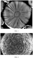
- cross-sectional screenshots of the ternary precursor may be measured using a Zeiss SIGMA 300 scanning electron microscope SEM.
- a plurality (for example, 20) of cross-sections of the particles of the ternary precursor may be taken to measure respective inner core radii and shell thicknesses so as to obtain an average value.
- a molecular formula of the inner core is [Ni x Co y Mn (1-x-y )](OH) 2 , where 0.8 ⁇ x ⁇ 1.0, 0 ⁇ y ⁇ 0.2, and x + y ⁇ 1;
- the Ni content in the inner core of the ternary precursor being made higher than or equal to the Ni content in the shell means a decreased Ni content in the ternary precursor while maintaining a high Ni content in the particles of the ternary precursor. This can reduce side reactions between the surface of the ternary positive electrode material prepared with such ternary precursor and electrolyte while maintaining a high capacity of secondary batteries, thereby further improving the cycling performance and storage performance of secondary batteries.
- a volume distribution span of particles of the ternary precursor is (D v 90 - D v 10)/D v 50 ⁇ 1.3.
- the ternary precursor of this application has a wide particle size distribution and therefore helps to increase the compacted density of the ternary positive electrode prepared with such ternary precursor, thereby further increasing the volumetric energy density of the ternary positive electrode material.
- a volume-based median particle size D v 50 of particles of the ternary precursor is 5-15 ⁇ m, and optionally 5-10 ⁇ m.
- the volume-based median particle size of the ternary precursor falling within the given range can further increase the capacity of the ternary positive electrode material prepared with such ternary precursor.
- volume-based particle sizes D v 10, D v 50, D v 90 of the particles of the ternary precursor are concepts well known in the art.
- D v 10 is a particle size at which cumulative distribution by volume of power particles reaches 10% as counted from the small particle size side, generally measured in ⁇ m.
- D v 50 is a particle size at which cumulative distribution by volume of power particles reaches 50% as counted from the small particle size side, generally measured in ⁇ m.
- D v 90 is a particle size at which cumulative distribution by volume of power particles reaches 90% as counted from the small particle size side, generally measured in ⁇ m.
- the volume-based particle sizes D v 10, D v 50, D v 90 of the particles of the ternary precursor may be tested by using a method well known in the art.
- the particle sizes may be determined using a Malvern 2000 instrument in accordance with the GB/T 19077-2016/ISO 13320:2009 "Particle size distribution laser diffraction method".
- a specific surface area BET of particles of the ternary precursor is 5-20 m 2 /g, and optionally 7-15 m 2 /g.
- the BET of the ternary precursor falling within the given range helps to obtain sintered primary particles with high crystallinity, thereby helping to improve the capacity and long-term cycling performance of the ternary positive electrode material.
- the specific surface area BET of the particles of the ternary precursor may be tested by using a method well known in the art.
- the specific surface area may be determined using a TriStar II 3020 instrument in accordance with GB/T 19587-2017 "Determination of specific surface area of solid substances by gas adsorption BET method".
- a tap density TD of particles of the ternary precursor is ⁇ 1.9 g/cm 3 .
- a higher TD of the ternary precursor means a higher tap density of a sintered ternary positive electrode material, and hence a higher compacted density and energy density of the ternary positive electrode material.
- the tap density TD of the particles of the ternary precursor may be tested by using a method well known in the art.
- the tap density may be determined using a Bettersize BT-300 powder tap density tester in accordance with GB/T 5162-2006 "Metallic powders-determination of tap density”.
- the cracking rate of the ternary precursor falls within the given range at a pressure of 5 tons, the particles of the ternary precursor have a higher pressure-resistant strength and higher structural stability.
- the cracking rate of the particles of the ternary precursor may be tested by using a method well known in the art.
- the cracking rate may be determined using the steps in the following test method: first, a pressure environment is created using external force following the compacted density test method, and original powder and compacted powder are placed in separate bags for storage; and second, the two bags of powder are placed in a laser particle size analyzer for test, with an input parameter set to D v 1, and data are substituted into a cracking rate formula to find a corresponding numerical value.
- the ternary precursor is doped with element M, where element M is one or more of Zr, W, Al, Sr, Ti, Ca, Sb, Mg, Zn, Te, and Fe. Uniformly doping the element into the ternary precursor helps to improve the structural stability, thereby further improving the cycling stability of the ternary positive electrode material prepared with such ternary precursor.
- An embodiment of this application provides a preparation method of ternary precursor.
- the preparation method includes the following steps:
- both nucleation and nucleus growth are present only in seed crystal synthesis of step S2, and only nucleus growth is present in step S3.
- the seed crystals required for continuous production come from the continuous addition of the seed crystal slurry synthesized in step S2, which helps to control the process stability during the continuous production in step S3, and can generate a shell layer structure on the inner core in the radial distribution.
- the deformation stacking fault probability of the ternary precursor being controlled to be not greater than 2.5% can help to improve the structural stability of the ternary positive electrode material prepared with such ternary precursor.
- a ternary precursor having an inner core-shell structure can be obtained, and the difference of principal components of the shell and inner core can be controlled, thereby further improving the structural stability and extractable capacity of the ternary material prepared with such ternary precursor.
- a molar ratio of nickel, cobalt, and manganese in the first mixed nickel-cobalt-manganese metal salt solution is x:y:(1 - x - y), where 0.8 ⁇ x ⁇ 1.0, 0 ⁇ y ⁇ 0.2, and x + y ⁇ 1; and a molar ratio of nickel, cobalt, and manganese in the second mixed nickel-cobalt-manganese metal salt solution is a:b:(1 - a- b), where 0.8 ⁇ a ⁇ 1.0, 0 ⁇ b ⁇ 0.2, a + b ⁇ 1, and a ⁇ x.
- the first and second mixed nickel-cobalt-manganese metal salt solutions are prepared from a nickel salt, a cobalt salt, a manganese salt, and pure water.
- the nickel salt may be one of nickel nitrate, nickel acetate, and nickel sulfate.
- the cobalt salt may be one of cobalt nitrate, cobalt acetate, and cobalt sulfate.
- the manganese salt may be one of manganese nitrate, manganese acetate, and manganese sulfate.
- step S1 the concentration of the first and second mixed nickel-cobalt-manganese metal salt solutions are 0.5-2.5 mol/L.
- the first pH value is 11.5-12.5, and optionally 11.8-12.2; and the first ammonia concentration is 0.2-0.6 mol/L, and optionally 0.3-0.5 mol/L.
- seeds crystal having a volume-based median particle size D v 50 of 0.1-5 ⁇ m can be stably synthesized.
- a stirring linear velocity is 5.0-7.0 m/s.
- the second pH value is 11.0-12.0, and optionally 11.1-11.7; and the second ammonia concentration is 0.2-0.6 mol/L, and optionally 0.3-0.5 mol/L.
- a solid-liquid ratio of the seed crystal slurry of ternary precursor in the second reactor is 0.1-0.2.
- step S3 the stirring linear velocity is 3.0-6.0 m/s.
- the temperature is 40-75°C.
- the alkali solution is a sodium hydroxide solution with a concentration of 1-10 mol/L.
- a concentration of the ammonia is 2-14 mol/L.
- a volume-based median particle size D v 50 of the seed crystal slurry of ternary precursor is 1-5 ⁇ m; and a volume-based median particle size D v 50 of the ternary precursor is 5-15 ⁇ m, and optionally 5-10 ⁇ m.
- the first and/or second mixed nickel-cobalt-manganese metal salt solution may further contain 0.01-2% of element M based on a total mole number of nickel, cobalt, and manganese.
- Element M may be one or more of Zr, W, Al, Sr, Ti, Ca, Sb, Mg, Zn, Te, and Fe.
- An embodiment of this application provides a ternary positive electrode material prepared with the ternary precursor of the first aspect of this application.
- the ternary positive electrode material includes secondary particles formed by aggregation of a plurality of primary particles, where the plurality of primary particles are arranged in a radial direction of the secondary particles, as shown in FIG. 2 . Radial distribution of the ternary positive electrode material facilitates lithium ion transport during charge and discharge, thereby improving the cycling performance of secondary batteries.
- a volume-based median particle size D v 50 of the ternary positive electrode material is 5-15 ⁇ m, and optionally 5-10 ⁇ m.
- the volume-based median particle size D v 50 falling within the given range can further improve the electrochemical performance of the ternary positive electrode material.
- the molecular composition of the ternary positive electrode material is Li z Ni c Co d Mn( 1-c-d )O e , where 0.95 ⁇ z ⁇ 1.05, 0.8 ⁇ c ⁇ 1.0, 0 ⁇ d ⁇ 0.2, c + d ⁇ 1, and 1.8 ⁇ e ⁇ 2.2.
- the ternary positive electrode material is doped with element M1.
- Element M1 is one or more of Fe, Cr, Ti, Zn, Sr, V, Al, Zr, Ce, Mg, F, Sb, N, and B, and the doping amount of element M1 is 100-5000 ppm by weight of the ternary positive electrode material.
- the particle surface of the ternary positive electrode material has a coating layer containing element M2, the element M2 being one or more of Ti, Al, B, Co, Mg, P, Sr, and V, and a coating amount of the element M2 is 100-20000 ppm by weight of the ternary positive electrode material, optionally 1000-13000 ppm.
- the ternary positive electrode material being doped with the element can significantly improve the structural stability of the ternary positive electrode material.
- the ternary positive electrode material being coated with the element can significantly reduce interface side reactions, thereby further improving the cycling performance of secondary batteries.
- the preparation method of ternary positive electrode material includes:
- a water washing step may be selectively performed between steps (1) and (2).
- the water washing step includes placing the primary sintered material obtained in step (1) into a washing liquid for washing, followed by centrifugation and vacuum drying.
- the washing liquid may be pure water, ethanol, or a mixture thereof, a solid-liquid ratio of the washing liquid is 1:(0.5-2), a washing time is 0.5-10 min, and a washing temperature is 25-50°C.
- the lithium-containing compound is not limited to any particular type in the embodiments of this application, and may be selected based on actual needs.
- the lithium-containing compound may be lithium hydroxide, lithium carbonate, or lithium nitrate.
- the M1-containing compound or the M2-containing compound is not limited to any particular type in the embodiments of this application, and may be selected based on actual needs.
- the M1-containing compound may be selected from oxide of M1, chloride of M1, sulfate of M1, nitrate of M1, carbonate of M1, or bicarbonate of M1.
- the M2-containing compound may be selected from oxide of M2, chloride of M2, sulfate of M2, nitrate of M2, carbonate of M2, or bicarbonate of M2.
- a ratio of a mole number of lithium in the lithium-containing compound to a sum of mole numbers of nickel, cobalt, and manganese in the ternary precursor is 1:(1.0-1.2).
- a sintering atmosphere in the atmosphere furnace may be air or oxygen, and optionally oxygen.
- An oxygen concentration in the atmosphere furnace is 50-100%. Further optionally, the oxygen concentration in the atmosphere furnace is 80-100%.
- a temperature for primary sintering is 700-950°C. Such temperature in primary sintering is maintained for 5-25 h, and optionally for 10-20 h.
- a temperature for secondary sintering is 200-700°C, and optionally 300-700°C. Such temperature in secondary sintering is maintained for 5-15 h, and optionally for 5-10 h.
- An embodiment of this application provides a secondary battery.
- the secondary battery includes a positive electrode plate, a negative electrode plate, an electrolyte, and a separator.
- active ions are intercalated and deintercalated between the positive electrode plate and the negative electrode plate.
- the electrolyte conducts ions between the positive electrode plate and the negative electrode plate.
- the separator is disposed between the positive electrode plate and the negative electrode plate to mainly prevent a short circuit between positive and negative electrodes and to allow the ions to pass through.
- the positive electrode plate includes a positive electrode current collector and a positive electrode film layer disposed on at least one surface of the positive electrode current collector, and the positive electrode film layer includes the ternary positive electrode material in the third aspect of this application.
- the positive electrode current collector includes two opposite surfaces in its thickness direction, and the positive electrode film layer is disposed on either or both of the two opposite surfaces of the positive electrode current collector.
- the positive electrode current collector may be a metal foil current collector or a composite current collector.
- an aluminum foil may be used as the metal foil.
- the composite current collector may include a polymer material matrix and a metal layer formed on at least one surface of the polymer material matrix.
- the composite current collector may be formed by forming a metal material (aluminum, aluminum alloy, nickel, nickel alloy, titanium, titanium alloy, silver, silver alloy, or the like) on a polymer material matrix (for example, matrices of polypropylene (PP), polyethylene terephthalate (PET), polybutylene terephthalate (PBT), polystyrene (PS), and polyethylene (PE)).
- PP polypropylene
- PET polyethylene terephthalate
- PBT polybutylene terephthalate
- PS polystyrene
- PE polyethylene
- the positive electrode film layer may further optionally include a binder.
- the binder may include at least one of polyvinylidene fluoride (PVDF), polytetrafluoroethylene (PTFE), vinylidene fluoride-tetrafluoroethylene-propylene terpolymer, vinylidene fluoride-hexafluoropropylene-tetrafluoroethylene terpolymer, tetrafluoroethylene-hexafluoropropylene copolymer, and fluorine-containing acrylic resin.
- PVDF polyvinylidene fluoride
- PTFE polytetrafluoroethylene
- PTFE polytetrafluoroethylene
- vinylidene fluoride-tetrafluoroethylene-propylene terpolymer vinylidene fluoride-hexafluoropropylene-tetrafluoroethylene terpolymer
- the positive electrode film layer further optionally includes a conductive agent.
- the conductive agent may be selected from more than one of superconducting carbon, acetylene black, carbon black, Ketjen black, carbon dots, carbon nanotubes, graphene, and carbon nanofiber.
- the positive electrode plate may be prepared by using the following manners: the compositions used for preparing the positive electrode plate, for example, the ternary positive electrode material, the conductive agent, the binder, and any other compositions, are dispersed in a solvent (for example, N-methylpyrrolidone) to form a positive electrode slurry.
- a solvent for example, N-methylpyrrolidone
- the positive electrode slurry is applied onto the positive electrode current collector, and processes such as drying and cold pressing are performed to obtain the positive electrode plate.
- the negative electrode plate includes a negative electrode current collector and a negative electrode film layer disposed on at least one surface of the negative electrode current collector, where the negative electrode film layer includes a negative electrode active material.
- the negative electrode current collector includes two opposite surfaces in its thickness direction, and the negative electrode film layer is disposed on either or both of the two opposite surfaces of the negative electrode current collector.
- the negative electrode current collector may be a metal foil current collector or a composite current collector.
- a metal foil a copper foil may be used.
- the composite current collector may include a polymer material matrix and a metal layer formed on at least one surface of the polymer material matrix.
- the composite current collector may be formed by forming a metal material (copper, copper alloy, nickel, nickel alloy, titanium, titanium alloy, silver, or silver alloy) on the polymer material matrix (for example, matrices of polypropylene (PP), polyethylene terephthalate (PET), polybutylene terephthalate (PBT), polystyrene (PS), and polyethylene (PE)).
- PP polypropylene
- PET polyethylene terephthalate
- PBT polybutylene terephthalate
- PS polystyrene
- PE polyethylene
- the negative electrode active material may be a well-known negative electrode active material used for a battery in the art.
- the negative electrode active material may include at least one of the following materials: artificial graphite, natural graphite, soft carbon, hard carbon, silicon-based material, tin-based material, and lithium titanate.
- the silicon-based material may be selected from at least one of elemental silicon, silicon-oxygen compound, silicon-carbon composite, silicon-nitrogen composite, and silicon alloy.
- the tin-based material may be selected from at least one of elemental tin, tin-oxygen compound, and tin alloy.
- this application is not limited to these materials, but may use other conventional materials that can be used as negative electrode active materials for batteries instead.
- One type of these negative electrode active materials may be used alone, or two or more types may be used in combination.
- the negative electrode film layer may further optionally include a binder.
- the binder may be selected from at least one of styrenebutadiene rubber (SBR), polyacrylic acid (PAA), polyacrylic acid sodium (PAAS), polyacrylamide (PAM), polyvinyl alcohol (PVA), sodium alginate (SA), polymethacrylic acid (PMAA), and carboxymethyl chitosan (CMCS).
- the negative electrode film layer further optionally includes a conductive agent.
- the conductive agent may be selected from at least one of superconducting carbon, acetylene black, carbon black, Ketjen black, carbon dots, carbon nanotubes, graphene, and carbon nanofiber.
- the negative electrode film layer may further optionally include other promoters such as a thickener (for example, sodium carboxymethyl cellulose (CMC-Na)).
- a thickener for example, sodium carboxymethyl cellulose (CMC-Na)
- the negative electrode plate may be prepared in the following manner: the compositions used for preparing the negative electrode plate, for example, the negative electrode active material, the conductive agent, the binder, and any other compositions, are dispersed in a solvent (for example, deionized water) to form a negative electrode slurry; and the negative electrode slurry is applied onto the negative electrode current collector, followed by processes such as drying and cold pressing to obtain the negative electrode plate.
- a solvent for example, deionized water
- the electrolyte conducts ions between the positive electrode plate and the negative electrode plate.
- the electrolyte is not specifically limited to any particular type in this application, and may be selected based on needs.
- the electrolyte may be in a liquid state, a gel state, or an all-solid state.
- the electrolyte is a liquid electrolyte.
- the liquid electrolyte includes an electrolytic salt and a solvent.
- the electrolytic salt may be selected from at least one of lithium hexafluorophosphate, lithium tetrafluoroborate, lithium perchlorate, lithium hexafluoroborate, lithium bis(fluorosulfonyl)imide, lithium bis-trifluoromethanesulfon imide, lithium trifluoromethanesulfonate, lithium difluorophosphate, lithium difluorooxalatoborate, lithium bisoxalatoborate, lithium difluorobisoxalate phosphate, and lithium tetrafluoro oxalate phosphate.
- the solvent may be selected from at least one of ethylene carbonate (EC), propylene carbonate, ethyl methyl carbonate, diethyl carbonate (DEC), dimethyl carbonate (DMC), dipropyl carbonate, methyl propyl carbonate, ethyl propyl carbonate, butylene carbonate, fluoroethylene carbonate, methyl formate, methyl acetate, ethyl acetate, propyl acetate, methyl propionate, ethyl propionate, propyl propionate, methyl butyrate, ethyl butyrate, 1,4-butyrolactone, sulfolane, methyl sulfonyl methane, ethyl methanesulfonate, and diethyl sulfone.
- EC ethylene carbonate
- DEC diethyl carbonate
- DMC dimethyl carbonate
- fluoroethylene carbonate fluoroethylene carbonate
- methyl formate
- the liquid electrolyte further optionally includes an additive.
- the additive may include a negative electrode film-forming additive, a positive electrode film-forming additive, or may include an additive that can improve some performance of batteries, for example, an additive for improving overcharge performance of batteries, an additive for improving high-temperature performance or low-temperature performance of batteries, and the like.
- the secondary battery further includes a separator.
- the separator is not limited to any particular type in this application, and may be any well-known porous separator with good chemical stability and mechanical stability.
- a material of the separator may be selected from at least one of glass fiber, non-woven fabric, polyethylene, polypropylene, and polyvinylidene fluoride.
- the separator may be a single-layer film or a multi-layer composite film, and is not particularly limited. When the separator is a multi-layer composite film, all layers may be made of same or different materials, which is not particularly limited.
- the positive electrode plate, the negative electrode plate, and the separator may be made into an electrode assembly through winding or lamination.
- the secondary battery may include an outer package.
- the outer package is used for packaging the electrode assembly and the electrolyte.
- the outer package of the secondary battery may be a hard shell, for example, a hard plastic shell, an aluminum shell, or a steel shell.
- the outer package of the secondary battery may alternatively be a soft package, for example, a soft pouch.
- a material of the soft pack may be plastic.
- polypropylene (PP), polybutylene terephthalate, and polybutylene succinate may be listed.
- the secondary battery is not limited to any particular shape in this application, and may be cylindrical, rectangular, or any other shape.
- FIG. 6 shows a secondary battery 5 of a rectangular structure as an example.
- the outer package may include a housing 51 and a cover plate 53.
- the housing 51 may include a base plate and side plates connected to the base plate, and the base plate and the side plates enclose an accommodating cavity.
- the housing 51 has an opening communicating with the accommodating cavity, and the cover plate 53 can cover the opening to close the accommodating cavity.
- the positive electrode plate, the negative electrode plate, and the separator may be made into an electrode assembly 52 through winding or lamination.
- the electrode assembly 52 is packaged in the accommodating cavity.
- the electrolyte infiltrates the electrode assembly 52.
- the secondary battery may be used to assemble a battery module, and the battery module may include one or more secondary batteries.
- the specific quantity may be chosen by persons skilled in the art based on use and capacity of the battery module.
- FIG. 8 shows a battery module 4 as an example.
- a plurality of secondary batteries 5 may be sequentially arranged in a length direction of the battery module 4.
- the batteries may alternatively be arranged in any other manners.
- the plurality of secondary batteries 5 may be fastened through fasteners.
- the battery module 4 may further include a housing with an accommodating space, and the plurality of secondary batteries 5 are accommodated in the accommodating space.
- the battery module may be used to assemble a battery pack, one or more battery modules may be included in the battery pack, and the specific quantity may be chosen by persons skilled in the art based on use and capacity of the battery pack.
- FIG. 9 and FIG. 10 show a battery pack 1 as an example.
- the battery pack 1 may include a battery box and a plurality of battery modules 4 arranged in the battery box.
- the battery box includes an upper box body 2 and a lower box body 3.
- the upper box body 2 can cover the lower box body 3 to form an enclosed space for accommodating the battery module 4.
- the plurality of battery modules 4 may be arranged in the battery box in any manner.
- this application further provides an electric apparatus.
- the electric apparatus includes at least one of the secondary battery, the battery module, or the battery pack provided in this application.
- the secondary battery, the battery module, or the battery pack may be used as a power source for the electric apparatus or an energy storage unit of the electric apparatus.
- the electric apparatus may include a mobile device (for example, a mobile phone or a notebook computer), an electric vehicle (for example, a battery electric vehicle, a hybrid electric vehicle, a plug-in hybrid electric vehicle, an electric bicycle, an electric scooter, an electric golf vehicle, or an electric truck), an electric train, a ship, a satellite system, an energy storage system, or the like, but is not limited thereto.
- the secondary battery, the battery module, or the battery pack may be selected for the electric apparatus based on requirements for using the electric apparatus.
- FIG. 11 shows an electric apparatus as an example.
- This electric apparatus is a battery electric vehicle, a hybrid electric vehicle, a plug-in hybrid electric vehicle, or the like.
- a battery pack or a battery module may be used.
- the electric apparatus may be a mobile phone, a tablet computer, a notebook computer, or the like.
- the electric apparatus is usually required to be light and thin, and the secondary battery may be used as a power source.
- Nickel sulfate, cobalt sulfate, and manganese sulfate at a molar ratio of nickel, cobalt, and manganese of 95:3:2 were added into pure water to prepare a first mixed nickel-cobalt-manganese metal salt solution having a concentration of 2.0 mol/L, and nickel sulfate, cobalt sulfate, and manganese sulfate at a molar ratio of nickel, cobalt, and manganese of 90:5:5 were added into pure water to prepare a second mixed nickel-cobalt-manganese metal salt solution having a concentration of 2.0 mol/L.
- the first mixed nickel-cobalt-manganese metal salt solution, the NaOH solution, and the ammonia aqueous solution were added to the first reactor, where a flow ratio of the first mixed nickel-cobalt-manganese metal salt solution to the NaOH solution was 5:4 and a flow ratio of the NaOH solution to the ammonia aqueous solution was 15: 1, to maintain the pH value and the ammonia concentration in the first reactor unchanged, so as to continuously react to synthesize a seed crystal slurry.
- the second mixed nickel-cobalt-manganese metal salt solution, the NaOH solution, the ammonia aqueous solution, and the seed crystal slurry were added to the second reactor, where a flow ratio of the second mixed nickel-cobalt-manganese metal salt solution to the NaOH solution was 5:4, a flow ratio of the NaOH solution to the ammonia aqueous solution was 15:1, and a flow ratio of the seed crystal slurry to the second mixed nickel-cobalt-manganese metal salt solution was 0.15, to maintain the pH value and the ammonia concentration in the second reactor unchanged, so as to continuously react to synthesize a ternary precursor slurry.
- the slurry was then centrifuged at 300 rpm for 20 min, followed by deionized water washing, filtering, and drying at 105°C for 10 h, to obtain a ternary precursor product.
- the final precursor product has an inner core of [Ni 0.95 Co 0.03 Mn 0.02 ](OH) 2 and a shell of [Ni 0.90 Co 0.05 Mn 0.05 ](OH) 2 .
- Step S2 the pH value was 12.1 and the stirring linear velocity was 6.2 m/s, and that in step S3, the pH value was 11.48 and the ammonia concentration was 0.34 mol//L.
- Step S2 the pH value was 12.2 and the stirring linear velocity was 6.4 m/s, and that in step S3, the pH value was 11.45 and the ammonia concentration was 0.36 mol//L.
- Step S2 Preparation processes of the ternary precursor and the ternary positive electrode material basically followed that of Example 1-1, except that in step S2, the pH value was 12.3 and the stirring linear velocity was 7 m/s, and that in step S3, the pH value was 11.43 and the ammonia concentration was 0.40 mol//L.
- step S2 Preparation processes of the ternary precursor and the ternary positive electrode material basically followed that of Example 1-1, except that in step S2, the pH value was 12.5, the ammonia concentration was 0.2 mol/L, the stirring linear velocity was 7 m/s, and the reaction temperature was 40°C, and that in step S3, the pH value was 11.4 and the ammonia concentration was 0.5 mol//L.
- Step S2 Preparation processes of the ternary precursor and the ternary positive electrode material basically followed that of Example 1-1, except that in step S2, the pH value was 12.3, the ammonia concentration was 0.25 mol/L, and the stirring linear velocity was 7 m/s, and that in step S3, the pH value was 11.4 and the ammonia concentration was 0.5 mol//L.
- step S2 Preparation processes of the ternary precursor and the ternary positive electrode material basically followed that of Example 1-1, except that in step S2, the pH value was 11.5, the ammonia concentration was 0.6 mol/L, and the stirring linear velocity was 5 m/s, and that in step S3, the pH value was 11.4 and the ammonia concentration was 0.5 mol//L.
- Step S3 Preparation processes of the ternary precursor and the ternary positive electrode material basically followed that of Example 1-1, except that in step S3, the pH value was 12, the ammonia concentration was 0.2 mol//L, and the stirring linear velocity was 6 m/s.
- Step S3 Preparation processes of the ternary precursor and the ternary positive electrode material basically followed that of Example 1-1, except that in step S3, the pH value was 11.48, the ammonia concentration was 0.33 mol//L, and the stirring linear velocity was 5.2 m/s.
- Step S1 Preparation processes of the ternary precursor and the ternary positive electrode material basically followed that of Example 1-1, except that in step S1, the molar ratio of nickel, cobalt, and manganese in the first mixed nickel-cobalt-manganese metal salt solution was 90:5:5.
- step S1 the molar ratio of nickel, cobalt, and manganese in the first mixed nickel-cobalt-manganese metal salt solution was 85:10:5, and the molar ratio of nickel, cobalt, and manganese in the second mixed nickel-cobalt-manganese metal salt solution was 80:10:10.
- step S1 Preparation processes of the ternary precursor and the ternary positive electrode material basically followed that of Example 1-1, except that in step S1, the molar ratio of nickel, cobalt, and manganese in both the first and second mixed nickel-cobalt-manganese metal salt solutions was 80:10:10.
- Step S2 the pH value was 12.1 and the stirring linear velocity was 6.2 m/s, and that in step S3, the pH value was 11.52 and the ammonia concentration was 0.32 mol//L.
- Step S2 the pH value was 12.15 and the stirring linear velocity was 6.3 m/s, and that in step S3, the pH value was 11.48 and the ammonia concentration was 0.34 mol//L.
- Step S2 the pH value was 12.2 and the stirring linear velocity was 6.5 m/s, and that in step S3, the pH value was 11.45 and the ammonia concentration was 0.36 mol//L.
- Step S2 Preparation processes of the ternary precursor and the ternary positive electrode material basically followed that of Example 1-1, except that in step S2, the pH value was 12.3 and the stirring linear velocity was 6.8 m/s, and that in step S3, the pH value was 11.43 and the ammonia concentration was 0.38 mol//L.
- Step S2 Preparation processes of the ternary precursor and the ternary positive electrode material basically followed that of Example 1-1, except that in step S2, the pH value was 12.6, the ammonia concentration was 0.8 mol/L, and the stirring linear velocity was 4.5 m/s, and that in step S3, the pH value was 12.1, the ammonia concentration was 0.9 mol//L, and that in step (1), no ZrO 2 was added.
- Step S3 Preparation processes of the ternary precursor and the ternary positive electrode material basically followed that of Example 1-1, except that in step S3 the second mixed nickel-cobalt-manganese metal salt solution, the NaOH solution, and the ammonia solution were added into the second reactor.
- ternary precursor and the ternary positive electrode material basically followed that of Example 1-1, except that the ternary precursor was prepared in the following method: 20 L pure water was added as a base solution in a 100 L reactor, a 5 mol/L NaOH solution was added to adjust a pH value of the base solution to 11.5, a 9 mol/L aqueous ammonia solution was added to adjust the ammonia concentration of the base solution to 0.3 mol/L, stirring was started at a linear velocity of 5 m/s, and a reaction temperature of 50°C was maintained.
- a mixed nickel-cobalt-manganese metal salt solution having a concentration of 2.0 mol/L (with a molar ratio 90:5:5 of nickel, cobalt, and manganese), a NaOH solution, and an ammonia aqueous solution were added to the reactor, where a flow ratio of the mixed nickel-cobalt-manganese metal salt solution to the NaOH solution was 5:4, and a flow ratio of the NaOH solution to the ammonia aqueous solution was 15: 1, to maintain the pH value and the ammonia concentration in the reactor unchanged, so as to continuously react to synthesize a ternary precursor slurry.
- the slurry was then centrifuged, washed, filtered, and dried to obtain a high-nickel ternary precursor product.
- the molecular formula of the final precursor product was [Ni 0.90 Co 0.05 Mn 0.05 ](OH) 2 .
- the deformation stacking fault probability f D of the ternary precursor was tested in the following method: firstly, a Broker D8DISCOER X-ray diffractometer was used to perform X-ray diffraction on the precursor powder, and then perform a slow (1°/min) scan at a 2 ⁇ angle of 10-70°; secondly, spectral fitting is performed to obtain diffraction peak related parameters of the (001) crystal plane, (101) crystal plane, or (102) crystal plane; and thirdly, the related parameters were substituted into the expression to find the deformation stacking fault probability.
- the inner core radius and shell thickness of the particles of the ternary precursor were tested in the following method: cross-sectional screenshots of the ternary precursor were measured using a Zeiss SIGMA 300 scanning electron microscope SEM. To ensure the accuracy of test values, a plurality (for example, 20) of cross-sections of the particles of the ternary precursor might be taken to measure respective inner core radii and shell thicknesses so as to calculate an average value.
- the cracking rate of the particles of the ternary precursor was tested in the following method: firstly, a pressurized environment was created with external force by following a compacted density test method, and original powder and compacted powder were placed in separate bags for storage; and secondly, the two bags of powder were placed in a laser particle size analyzer for test, indexes D v 1 were output, and data were substituted into a cracking rate formula to find a corresponding numerical value.
- the volume-based particle size was tested by using a Malvern 2000 device in accordance with the GB/T 19077-2016/ISO 13320:2009 "Particle size distribution laser diffraction method". A clean beaker was taken, added with an appropriate amount of a sample under test until a shading degree was 8%-12%, and then added with 20 ml deionized water. A resulting mixture was subjected to external ultrasound for 5 min, and then a particle size tester was powered on to start testing.
- the specific surface area BET of the ternary precursor was measured using a TriStar II 3020 device in accordance with GB/T 19587-2017 "Determination of specific surface area of solid substances by gas adsorption BET method”.
- a dedicated sample tube for crystallization was taken, a test sample was added into the sample tube with a sampling spoon until the sample reached 2/3 of the bulb, and then the outside of the tube was wiped clean with dust-free paper. Then the sample tube was loaded to a degassing station of the device so as to degas the sample tube. Finally, the sample was placed into an analysis station for sample analysis.
- the tap density TD of the ternary precursor was tested by using a tap density tester in accordance with GB/T 5162-2006 "Metallic powders-determination of tap density”. Firstly, a clean and dry 100 ml graduated cylinder was weighed as m 0 g, filled with a specific amount of powder sample and weighted as m 1 g. The graduated cylinder filled with the powder material was placed onto a tap density tester which was then started and set with a vibration frequency of 5000 times. After vibration, a volume V cm 3 was taken. The tap density was equal to (m 1 -m 0 )/V, measured in g/cm 3 .
- a glue for sample preparation (dispersing PVDF into N-methylpyrrolidone, with a proportion of PVDF being about 8%) and sample powder were mixed uniform (the powder is about 5 times the weight of the glue) and applied onto a copper foil, which was then dried at 60°C for 30 min.
- the prepared sample was cut into pieces with a size of 6 mm by 6 mm using a scissor.
- a sample piece was fixed on a sample stage and put into an ion polisher (model: IB-19500CP). An edge of the sample piece was adjusted to be parallel to the center line: the X axis, with a distance of 40-60 ⁇ m to the Y axis, and then cutting was performed.
- the ternary positive electrode material prepared in the foregoing examples and comparative examples, PVDF, and conductive carbon were added at a weight ratio of 90:5:5 into N-methylpyrrolidone and stirred in a drying room to obtain a slurry.
- the slurry was applied onto an aluminum foil, followed by drying and cold pressing, to obtain a positive electrode plate.
- a lithium sheet was used as a negative electrode plate, an electrolyte was 1 mol/L LiPF 6 /(EC + DEC + DMC) (at a volume ratio of 1:1:1), and a button cell was assembled in a button cell box.
- the foregoing prepared button cell was charged to 4.3 V at 0.1C under a voltage of 2.8-4.3 V, and then was charged at a constant voltage of 4.3 V to a current less than or equal to 0.05 mA. After the button cell was left standing for 2 min, a charge capacity at that point was recorded as C 0 . Then, the button cell was discharged to 2.8 V at 0.1C, and a discharge capacity at that point was an initial gram capacity and recorded as D 0 . The first-cycle efficiency was D 0 /C 0 ⁇ 100%.
- the ternary positive electrode materials prepared in the foregoing examples and comparative examples were used as a positive electrode active substance.
- the positive electrode active substance, a conductive agent acetylene black, and a binder PVDF at a weight ratio of 94:3:3 were fully stirred and uniformly mixed in an N-methylpyrrolidone solvent system, and then a resulting mixture was applied onto an aluminum foil, followed by drying and cold pressing, to obtain a positive electrode plate.
- a negative electrode active material artificial graphite, hard carbon, a conductive agent acetylene black, a binder SBR, and a thickener sodium carboxymethyl cellulose (CMC) at a weight ratio of 90:5:2:2:1 were fully stirred and mixed uniform in a deionized water solvent system, and then a resulting mixture was applied onto a copper foil, followed by drying and cold pressing to obtain a negative electrode plate.
- a porous polyethylene polymeric film was used as a separator. The positive electrode plate, the separator, and the negative electrode plate were stacked in order, so that the separator was placed between the positive and negative electrodes for separation, and winding was performed to obtain a bare cell.
- the bare cell was placed in an outer package, the prepared electrolyte, that is 1 mol/L LiPF 6 /(EC + DEC + DMC) (at a volume ratio of 1:1:1), was injected, and then the outer package was sealed to obtain a full cell.
- the prepared electrolyte that is 1 mol/L LiPF 6 /(EC + DEC + DMC) (at a volume ratio of 1:1:1)
- the foregoing prepared full cell was left standing for 5 min at a constant temperature of 25°C, and was discharged to 2.8 V at 1/3C. After being left standing for 5 min, the full cell was charged to 4.25 V at 1/3C, and was charged at a constant voltage of 4.25 V to a current less than or equal to 0.05 mA. After the full cell was left standing for 5 min, a charge capacity at that point was recorded as C 0 . Then, the full cell was discharged to 2.8 V at 1/3C, and a discharge capacity at that point was an initial gram capacity and recorded as D 0 .
- the full cell with 100% S°C (remaining capacity) was stored at 70°C.
- An OCV (open circuit voltage), IMP (impedance), volume (drainage method test) of the cell were measured before, during, and after storage. A residual capacity and reversible capacity of the cell were tested at the end of storage.
- the full cell was baked every 48 h, and left standing for 1 h, followed by OCV and IMP test. After the full cell was cooled to room temperature, a volume of the cell was tested in the drainage method. The test was finished after 30 days of storage, or storage continues until the volume swelled more than 50%.
- a protection voltage range was 2.7-4.3 V, and a nominal capacity was 2.25 Ah.
- the foregoing examples and comparative examples were tested respectively according to the foregoing processes, and the specific values are shown in Table 1 to Table 9.
- Table 1 Impact of deformation stacking fault probability of ternary precursor on battery performance No. Ternary precursor Battery performance Deformation stacking fault probability Button cell capacity at 0.1C (mAh/g) First-cycle efficiency (%) Fully cell capacity at 1/3C (mAh/g) Cycling capacity retention rate at 25°C (%) Cycling capacity retention rate at 45°C (%) Swelling volume after 30-day storage at 70°C (mL/Ah)
- Example 1-1 2.5 222 92.1 213 96.0 92.3 5.2
- Example 1-3 1.9 225 92.4 216 96.3 92.6 5.7
- the ternary precursor has an inner core of [Ni 0.95 Co 0.03 Mn 0.02 ](OH) 2 and a shell of [Ni 0.90 Co 0.05 Mn 0.05
- the ternary precursor has an inner core of [Ni 0.95 Co 0.03 Mn 0.02 ](OH) 2 and a shell of [Ni 0.90 Co 0.05 Mn 0.05 ](OH) 2 .
- Example 1-1 when the Ni content in the inner core of the ternary precursor is higher than or equal to the Ni content in the shell, the button cell capacities at 0.1C, the first-cycle efficiencies, the full cell capacities at 1/3C, the cycling capacity retention rates at 25°C after 300 cycles, and the cycling capacity retention rates at 45°C after 300 cycles are all good.
- the button cell capacities at 0.1C, the first-cycle efficiencies, the full cell capacities at 1/3C, the cycling capacity retention rates at 25°C after 300 cycles, and the cycling capacity retention rates at 45°C after 300 cycles are all further increased.
- Example 1-1 and Examples 8-1 to 8-3 By comprehensive comparison of Example 1-1 and Examples 8-1 to 8-3, when the ternary positive electrode materials are doped with these elements, the button cell capacities at 0.1C, the first-cycle efficiencies, the full cell capacities at 1/3C, the cycling capacity retention rates at 25°C after 300 cycles, the cycling capacity retention rates at 45°C after 300 cycles, and the swelling volume after 30-day storage at 70°C are all good.
- Comparative Example 1 in the preparation of the ternary precursor, in the process of shell formation and nucleus growth, no seed crystal slurry synthesized in step S2 is continuously added. As compared with Example 1, both nucleation and nucleus growth take place in the latter continuous production stage, and therefore it is difficult to control the process. This can neither help to produce products with good radial distribution nor synthesize products with an inner core-shell structure, resulting in low capacity, poor cycling, and high swelling rate of batteries. In Comparative Example 2, in the process of preparing the ternary precursor, the step S2 of seed crystal synthesis is omitted. Therefore, during the entire continuous growth process of the precursor, both nucleation and nucleus growth take place. Consequently, the synthesized precursor product has a high stacking fault probability, resulting in low capacity, poor cycling, and high swelling rate of batteries.
Landscapes
- Chemical & Material Sciences (AREA)
- Organic Chemistry (AREA)
- Inorganic Chemistry (AREA)
- Chemical Kinetics & Catalysis (AREA)
- Electrochemistry (AREA)
- General Chemical & Material Sciences (AREA)
- Engineering & Computer Science (AREA)
- Manufacturing & Machinery (AREA)
- Battery Electrode And Active Subsutance (AREA)
Applications Claiming Priority (2)
| Application Number | Priority Date | Filing Date | Title |
|---|---|---|---|
| CN202111102796.8A CN115838189B (zh) | 2021-09-18 | 2021-09-18 | 三元前驱体及其制备方法,三元正极材料以及用电装置 |
| PCT/CN2022/096551 WO2023040358A1 (zh) | 2021-09-18 | 2022-06-01 | 三元前驱体及其制备方法,三元正极材料以及用电装置 |
Publications (2)
| Publication Number | Publication Date |
|---|---|
| EP4234499A1 true EP4234499A1 (de) | 2023-08-30 |
| EP4234499A4 EP4234499A4 (de) | 2024-09-11 |
Family
ID=85574346
Family Applications (1)
| Application Number | Title | Priority Date | Filing Date |
|---|---|---|---|
| EP22868735.6A Pending EP4234499A4 (de) | 2021-09-18 | 2022-06-01 | Ternärer vorläufer und herstellungsverfahren dafür, ternäres positivelektrodenmaterial und elektrische vorrichtung |
Country Status (4)
| Country | Link |
|---|---|
| US (1) | US20240199439A1 (de) |
| EP (1) | EP4234499A4 (de) |
| CN (1) | CN115838189B (de) |
| WO (1) | WO2023040358A1 (de) |
Families Citing this family (4)
| Publication number | Priority date | Publication date | Assignee | Title |
|---|---|---|---|---|
| WO2024216600A1 (zh) * | 2023-04-20 | 2024-10-24 | 宁德时代新能源科技股份有限公司 | 前驱体材料及其制备方法、正极材料、正极极片、二次电池及用电装置 |
| CN116588986A (zh) * | 2023-05-11 | 2023-08-15 | 荆门市格林美新材料有限公司 | 一种高bet的小颗粒三元前驱体的制备方法 |
| CN120261571A (zh) * | 2024-01-02 | 2025-07-04 | 宁德时代新能源科技股份有限公司 | 正极材料及其制备方法、正极极片、电池和用电装置 |
| CN118206163B (zh) * | 2024-05-16 | 2024-10-18 | 南通金通储能动力新材料有限公司 | 一种制备低钠硫三元正极材料前驱体的方法 |
Family Cites Families (15)
| Publication number | Priority date | Publication date | Assignee | Title |
|---|---|---|---|---|
| JPH10310433A (ja) * | 1997-05-07 | 1998-11-24 | Ise Kagaku Kogyo Kk | リチウム二次電池用ニッケル水酸化物、ニッケル酸化物および正極活物質の製造方法 |
| CN104409716A (zh) * | 2014-10-30 | 2015-03-11 | 中国科学院过程工程研究所 | 一种具有浓度梯度的镍锂离子电池正极材料及其制备方法 |
| CN108123113B (zh) * | 2016-11-30 | 2020-07-10 | 比亚迪股份有限公司 | 正极活性材料前驱体及其制备方法、正极活性材料及其制备方法、正极和电池 |
| DE102017215146A1 (de) * | 2017-08-30 | 2019-02-28 | Bayerische Motoren Werke Aktiengesellschaft | POSITIVES AKTIVMATERIAL ZUR VERWENDUNG IN EINER SEKUNDÄREN LITHIUM-IONEN-Zelle und -BATTERIE |
| WO2019163845A1 (ja) * | 2018-02-22 | 2019-08-29 | 住友金属鉱山株式会社 | 金属複合水酸化物とその製造方法、非水電解質二次電池用正極活物質とその製造方法、および非水電解質二次電池 |
| CN108793268B (zh) * | 2018-06-19 | 2019-07-16 | 中南大学 | 核壳结构梯度镍钴锰三元正极材料前驱体及其制备方法 |
| CN108878818B (zh) * | 2018-06-19 | 2019-07-16 | 中南大学 | 核壳结构镍钴锰三元正极材料前驱体及其制备方法 |
| CN110002515B (zh) * | 2019-03-26 | 2021-10-01 | 南通金通储能动力新材料有限公司 | 一种高容量单晶型三元正极材料制备方法 |
| CN110422889B (zh) * | 2019-06-24 | 2021-07-16 | 当升科技(常州)新材料有限公司 | 锂离子电池正极材料前驱体和锂离子电池正极材料及各自的制备方法和锂离子电池 |
| KR102650925B1 (ko) * | 2019-12-30 | 2024-03-26 | 징멘 젬 컴퍼니 리미티드 | 종자 결정의 첨가량을 조절 및 제어하여 결정면의 우선적인 성장을 가지는 고니켈 삼원계 전구체의 제조방법 |
| CN111908521A (zh) * | 2020-08-10 | 2020-11-10 | 浙江帕瓦新能源股份有限公司 | 窄分布三元正极材料前驱体的制备方法 |
| CN112151790B (zh) * | 2020-08-26 | 2022-03-08 | 万华化学集团股份有限公司 | 高镍三元正极材料前驱体及其晶面可控生长的方法、三元正极材料及锂离子电池 |
| CN112421014A (zh) * | 2020-11-30 | 2021-02-26 | 蜂巢能源科技有限公司 | 一种高镍三元正极材料、其制备方法及锂离子电池 |
| CN112624213B (zh) * | 2020-12-18 | 2021-10-01 | 广东佳纳能源科技有限公司 | 三元前驱体的制备方法及三元前驱体、正极材料、锂离子电池 |
| CN112670473B (zh) * | 2020-12-23 | 2023-02-28 | 中伟新材料股份有限公司 | 三元前驱体及其制备方法、锂离子电池正极材料和锂离子电池 |
-
2021
- 2021-09-18 CN CN202111102796.8A patent/CN115838189B/zh active Active
-
2022
- 2022-06-01 WO PCT/CN2022/096551 patent/WO2023040358A1/zh not_active Ceased
- 2022-06-01 EP EP22868735.6A patent/EP4234499A4/de active Pending
-
2023
- 2023-05-23 US US18/322,010 patent/US20240199439A1/en active Pending
Also Published As
| Publication number | Publication date |
|---|---|
| US20240199439A1 (en) | 2024-06-20 |
| WO2023040358A1 (zh) | 2023-03-23 |
| CN115838189B (zh) | 2023-12-01 |
| EP4234499A4 (de) | 2024-09-11 |
| CN115838189A (zh) | 2023-03-24 |
Similar Documents
| Publication | Publication Date | Title |
|---|---|---|
| EP4220767B1 (de) | Modifiziertes ternäres positivelektrodenmaterial mit hohem nickelgehalt und herstellungsverfahren dafür sowie stromverbrauchende vorrichtung | |
| EP4234499A1 (de) | Ternärer vorläufer und herstellungsverfahren dafür, ternäres positivelektrodenmaterial und elektrische vorrichtung | |
| US20250140992A1 (en) | Secondary battery and apparatus containing the same | |
| CN117015872B (zh) | 正极活性材料、正极极片、二次电池和用电装置 | |
| EP4517875A1 (de) | Positivelektrodenaktivmaterial und herstellungsverfahren dafür, sekundärbatterie und elektrische vorrichtung | |
| KR20240068801A (ko) | 이차 전지 및 이차 전지를 포함하는 장치 | |
| EP4579810A1 (de) | Positivelektrodenmaterial und herstellungsverfahren dafür, positivelektrodenfolie, sekundärbatterie und elektrische vorrichtung | |
| EP4322259A1 (de) | Positivelektrodenmaterial, herstellungsverfahren dafür und sekundärbatterie damit | |
| US20250293252A1 (en) | Battery and electric device | |
| EP4510230A1 (de) | Positivelektrodenaktivmaterial, herstellungsverfahren dafür, sekundärbatterie und elektrische vorrichtung | |
| EP4481852A1 (de) | Positivelektrodenaktivmaterial, positivelektrodenfolie, elektrochemische energiespeichervorrichtung, sekundärbatterie, elektrische vorrichtung und herstellungsverfahren | |
| US20250246623A1 (en) | Positive electrode material and preparation method therefor, secondary battery comprising same, and power consuming device | |
| EP4239712A1 (de) | Positivelektrodenfolie, sekundärbatterie, batteriemodul, batteriepack und elektrische vorrichtung | |
| EP4604207A1 (de) | Zusammengesetztes positivelektrodenmaterial und herstellungsverfahren dafür, positivelektrodenplatte, sekundärbatterie und elektrische vorrichtung | |
| CN118431459B (zh) | 二次电池、用电装置及正极活性材料 | |
| US20230278886A1 (en) | Ternary precursor material, and preparation method and application thereof | |
| CN118648142A (zh) | 正极活性材料及其制备方法、正极极片、二次电池和用电装置 | |
| KR102940751B1 (ko) | 변성 하이니켈 삼원 양극재 및 이의 제조 방법, 및 전기기기 | |
| CN119833590B (zh) | 正极活性材料组合物、正极极片、电池及用电设备 | |
| EP4607609A1 (de) | Positivelektrodenaktivmaterial, positivpolteil, sekundärbatterie und elektrische vorrichtung | |
| CN121460667A (zh) | 二次电池、用电装置、正极活性材料及其制备方法 |
Legal Events
| Date | Code | Title | Description |
|---|---|---|---|
| STAA | Information on the status of an ep patent application or granted ep patent |
Free format text: STATUS: THE INTERNATIONAL PUBLICATION HAS BEEN MADE |
|
| PUAI | Public reference made under article 153(3) epc to a published international application that has entered the european phase |
Free format text: ORIGINAL CODE: 0009012 |
|
| STAA | Information on the status of an ep patent application or granted ep patent |
Free format text: STATUS: REQUEST FOR EXAMINATION WAS MADE |
|
| 17P | Request for examination filed |
Effective date: 20230523 |
|
| AK | Designated contracting states |
Kind code of ref document: A1 Designated state(s): AL AT BE BG CH CY CZ DE DK EE ES FI FR GB GR HR HU IE IS IT LI LT LU LV MC MK MT NL NO PL PT RO RS SE SI SK SM TR |
|
| A4 | Supplementary search report drawn up and despatched |
Effective date: 20240812 |
|
| RIC1 | Information provided on ipc code assigned before grant |
Ipc: H01M 4/525 20100101ALI20240806BHEP Ipc: H01M 4/505 20100101ALI20240806BHEP Ipc: C01G 45/00 20060101ALI20240806BHEP Ipc: C01G 51/00 20060101ALI20240806BHEP Ipc: C01G 53/00 20060101AFI20240806BHEP |
|
| RAP1 | Party data changed (applicant data changed or rights of an application transferred) |
Owner name: CONTEMPORARY AMPEREX TECHNOLOGY(HONG KONG) LIMITED |
|
| DAV | Request for validation of the european patent (deleted) | ||
| DAX | Request for extension of the european patent (deleted) |