EP4239712A1 - Positivelektrodenfolie, sekundärbatterie, batteriemodul, batteriepack und elektrische vorrichtung - Google Patents
Positivelektrodenfolie, sekundärbatterie, batteriemodul, batteriepack und elektrische vorrichtung Download PDFInfo
- Publication number
- EP4239712A1 EP4239712A1 EP22879653.8A EP22879653A EP4239712A1 EP 4239712 A1 EP4239712 A1 EP 4239712A1 EP 22879653 A EP22879653 A EP 22879653A EP 4239712 A1 EP4239712 A1 EP 4239712A1
- Authority
- EP
- European Patent Office
- Prior art keywords
- positive
- film layer
- electrode plate
- positive electrode
- positive film
- Prior art date
- Legal status (The legal status is an assumption and is not a legal conclusion. Google has not performed a legal analysis and makes no representation as to the accuracy of the status listed.)
- Pending
Links
- 239000002245 particle Substances 0.000 claims abstract description 200
- 239000007774 positive electrode material Substances 0.000 claims abstract description 52
- 239000000463 material Substances 0.000 claims abstract description 41
- 239000007787 solid Substances 0.000 claims abstract description 41
- 239000011149 active material Substances 0.000 abstract description 15
- 238000009792 diffusion process Methods 0.000 abstract description 9
- 238000006243 chemical reaction Methods 0.000 abstract description 6
- 239000010410 layer Substances 0.000 description 154
- 230000000052 comparative effect Effects 0.000 description 27
- -1 polypropylene Polymers 0.000 description 21
- 238000000034 method Methods 0.000 description 18
- 239000011267 electrode slurry Substances 0.000 description 17
- 238000012360 testing method Methods 0.000 description 17
- 239000003792 electrolyte Substances 0.000 description 14
- 229910001416 lithium ion Inorganic materials 0.000 description 13
- 239000011248 coating agent Substances 0.000 description 11
- 238000000576 coating method Methods 0.000 description 11
- 238000002360 preparation method Methods 0.000 description 11
- 239000011230 binding agent Substances 0.000 description 10
- 239000006258 conductive agent Substances 0.000 description 10
- OKTJSMMVPCPJKN-UHFFFAOYSA-N Carbon Chemical compound [C] OKTJSMMVPCPJKN-UHFFFAOYSA-N 0.000 description 9
- WHXSMMKQMYFTQS-UHFFFAOYSA-N Lithium Chemical compound [Li] WHXSMMKQMYFTQS-UHFFFAOYSA-N 0.000 description 9
- 229910052744 lithium Inorganic materials 0.000 description 9
- HBBGRARXTFLTSG-UHFFFAOYSA-N Lithium ion Chemical compound [Li+] HBBGRARXTFLTSG-UHFFFAOYSA-N 0.000 description 8
- 239000002131 composite material Substances 0.000 description 8
- 239000007773 negative electrode material Substances 0.000 description 8
- 230000008569 process Effects 0.000 description 8
- 239000002904 solvent Substances 0.000 description 8
- SECXISVLQFMRJM-UHFFFAOYSA-N N-Methylpyrrolidone Chemical compound CN1CCCC1=O SECXISVLQFMRJM-UHFFFAOYSA-N 0.000 description 7
- 239000002033 PVDF binder Substances 0.000 description 7
- 239000000654 additive Substances 0.000 description 7
- 230000000996 additive effect Effects 0.000 description 7
- 239000011888 foil Substances 0.000 description 7
- 229920002981 polyvinylidene fluoride Polymers 0.000 description 7
- 229910019142 PO4 Inorganic materials 0.000 description 6
- 239000004743 Polypropylene Substances 0.000 description 6
- 238000010586 diagram Methods 0.000 description 6
- 229910052751 metal Inorganic materials 0.000 description 6
- 239000002184 metal Substances 0.000 description 6
- 235000021317 phosphate Nutrition 0.000 description 6
- 239000002861 polymer material Substances 0.000 description 6
- 229920001155 polypropylene Polymers 0.000 description 6
- 239000000758 substrate Substances 0.000 description 6
- 239000004698 Polyethylene Substances 0.000 description 5
- 229910052782 aluminium Inorganic materials 0.000 description 5
- XAGFODPZIPBFFR-UHFFFAOYSA-N aluminium Chemical compound [Al] XAGFODPZIPBFFR-UHFFFAOYSA-N 0.000 description 5
- 150000001875 compounds Chemical class 0.000 description 5
- 150000002500 ions Chemical class 0.000 description 5
- 229910021437 lithium-transition metal oxide Inorganic materials 0.000 description 5
- VNWKTOKETHGBQD-UHFFFAOYSA-N methane Chemical compound C VNWKTOKETHGBQD-UHFFFAOYSA-N 0.000 description 5
- 239000010450 olivine Substances 0.000 description 5
- 229910052609 olivine Inorganic materials 0.000 description 5
- NBIIXXVUZAFLBC-UHFFFAOYSA-K phosphate Chemical compound [O-]P([O-])([O-])=O NBIIXXVUZAFLBC-UHFFFAOYSA-K 0.000 description 5
- 239000010452 phosphate Substances 0.000 description 5
- 229920001707 polybutylene terephthalate Polymers 0.000 description 5
- 229920000573 polyethylene Polymers 0.000 description 5
- RYGMFSIKBFXOCR-UHFFFAOYSA-N Copper Chemical compound [Cu] RYGMFSIKBFXOCR-UHFFFAOYSA-N 0.000 description 4
- PXHVJJICTQNCMI-UHFFFAOYSA-N Nickel Chemical compound [Ni] PXHVJJICTQNCMI-UHFFFAOYSA-N 0.000 description 4
- 229920000139 polyethylene terephthalate Polymers 0.000 description 4
- 239000005020 polyethylene terephthalate Substances 0.000 description 4
- 238000003825 pressing Methods 0.000 description 4
- 238000001878 scanning electron micrograph Methods 0.000 description 4
- 239000000243 solution Substances 0.000 description 4
- 239000012798 spherical particle Substances 0.000 description 4
- XEKOWRVHYACXOJ-UHFFFAOYSA-N Ethyl acetate Chemical compound CCOC(C)=O XEKOWRVHYACXOJ-UHFFFAOYSA-N 0.000 description 3
- RTAQQCXQSZGOHL-UHFFFAOYSA-N Titanium Chemical compound [Ti] RTAQQCXQSZGOHL-UHFFFAOYSA-N 0.000 description 3
- 150000001721 carbon Chemical class 0.000 description 3
- 239000001768 carboxy methyl cellulose Substances 0.000 description 3
- 239000011889 copper foil Substances 0.000 description 3
- 239000008367 deionised water Substances 0.000 description 3
- 229910021641 deionized water Inorganic materials 0.000 description 3
- 238000001035 drying Methods 0.000 description 3
- 239000008151 electrolyte solution Substances 0.000 description 3
- 238000004146 energy storage Methods 0.000 description 3
- 229920003023 plastic Polymers 0.000 description 3
- 239000004033 plastic Substances 0.000 description 3
- XLYOFNOQVPJJNP-UHFFFAOYSA-N water Chemical compound O XLYOFNOQVPJJNP-UHFFFAOYSA-N 0.000 description 3
- IXPNQXFRVYWDDI-UHFFFAOYSA-N 1-methyl-2,4-dioxo-1,3-diazinane-5-carboximidamide Chemical compound CN1CC(C(N)=N)C(=O)NC1=O IXPNQXFRVYWDDI-UHFFFAOYSA-N 0.000 description 2
- 229910001316 Ag alloy Inorganic materials 0.000 description 2
- 229910000990 Ni alloy Inorganic materials 0.000 description 2
- 229920002845 Poly(methacrylic acid) Polymers 0.000 description 2
- 239000004793 Polystyrene Substances 0.000 description 2
- 239000004372 Polyvinyl alcohol Substances 0.000 description 2
- BQCADISMDOOEFD-UHFFFAOYSA-N Silver Chemical compound [Ag] BQCADISMDOOEFD-UHFFFAOYSA-N 0.000 description 2
- 229910001069 Ti alloy Inorganic materials 0.000 description 2
- DPXJVFZANSGRMM-UHFFFAOYSA-N acetic acid;2,3,4,5,6-pentahydroxyhexanal;sodium Chemical compound [Na].CC(O)=O.OCC(O)C(O)C(O)C(O)C=O DPXJVFZANSGRMM-UHFFFAOYSA-N 0.000 description 2
- 239000006230 acetylene black Substances 0.000 description 2
- 239000013543 active substance Substances 0.000 description 2
- 229910021383 artificial graphite Inorganic materials 0.000 description 2
- 230000008901 benefit Effects 0.000 description 2
- 230000015572 biosynthetic process Effects 0.000 description 2
- 229910052799 carbon Inorganic materials 0.000 description 2
- 239000006229 carbon black Substances 0.000 description 2
- 239000002134 carbon nanofiber Substances 0.000 description 2
- 229910021393 carbon nanotube Inorganic materials 0.000 description 2
- 239000002041 carbon nanotube Substances 0.000 description 2
- 239000011247 coating layer Substances 0.000 description 2
- 238000005520 cutting process Methods 0.000 description 2
- 238000007599 discharging Methods 0.000 description 2
- 230000000694 effects Effects 0.000 description 2
- 125000002573 ethenylidene group Chemical group [*]=C=C([H])[H] 0.000 description 2
- FKRCODPIKNYEAC-UHFFFAOYSA-N ethyl propionate Chemical compound CCOC(=O)CC FKRCODPIKNYEAC-UHFFFAOYSA-N 0.000 description 2
- 238000002474 experimental method Methods 0.000 description 2
- 229910021389 graphene Inorganic materials 0.000 description 2
- 230000006872 improvement Effects 0.000 description 2
- 239000003273 ketjen black Substances 0.000 description 2
- GELKBWJHTRAYNV-UHFFFAOYSA-K lithium iron phosphate Chemical compound [Li+].[Fe+2].[O-]P([O-])([O-])=O GELKBWJHTRAYNV-UHFFFAOYSA-K 0.000 description 2
- DVATZODUVBMYHN-UHFFFAOYSA-K lithium;iron(2+);manganese(2+);phosphate Chemical compound [Li+].[Mn+2].[Fe+2].[O-]P([O-])([O-])=O DVATZODUVBMYHN-UHFFFAOYSA-K 0.000 description 2
- ILXAVRFGLBYNEJ-UHFFFAOYSA-K lithium;manganese(2+);phosphate Chemical compound [Li+].[Mn+2].[O-]P([O-])([O-])=O ILXAVRFGLBYNEJ-UHFFFAOYSA-K 0.000 description 2
- 230000014759 maintenance of location Effects 0.000 description 2
- 239000007769 metal material Substances 0.000 description 2
- TZIHFWKZFHZASV-UHFFFAOYSA-N methyl formate Chemical compound COC=O TZIHFWKZFHZASV-UHFFFAOYSA-N 0.000 description 2
- 229910052759 nickel Inorganic materials 0.000 description 2
- 238000011056 performance test Methods 0.000 description 2
- 229920002401 polyacrylamide Polymers 0.000 description 2
- 229920001343 polytetrafluoroethylene Polymers 0.000 description 2
- 239000004810 polytetrafluoroethylene Substances 0.000 description 2
- 229920002451 polyvinyl alcohol Polymers 0.000 description 2
- 150000003839 salts Chemical class 0.000 description 2
- 239000002210 silicon-based material Substances 0.000 description 2
- 229910052709 silver Inorganic materials 0.000 description 2
- 239000004332 silver Substances 0.000 description 2
- 239000000661 sodium alginate Substances 0.000 description 2
- 235000010413 sodium alginate Nutrition 0.000 description 2
- 229940005550 sodium alginate Drugs 0.000 description 2
- 235000019812 sodium carboxymethyl cellulose Nutrition 0.000 description 2
- 229920001027 sodium carboxymethylcellulose Polymers 0.000 description 2
- HHVIBTZHLRERCL-UHFFFAOYSA-N sulfonyldimethane Chemical compound CS(C)(=O)=O HHVIBTZHLRERCL-UHFFFAOYSA-N 0.000 description 2
- 229920001897 terpolymer Polymers 0.000 description 2
- 239000011366 tin-based material Substances 0.000 description 2
- 239000010936 titanium Substances 0.000 description 2
- 229910052719 titanium Inorganic materials 0.000 description 2
- 238000004804 winding Methods 0.000 description 2
- ZZXUZKXVROWEIF-UHFFFAOYSA-N 1,2-butylene carbonate Chemical compound CCC1COC(=O)O1 ZZXUZKXVROWEIF-UHFFFAOYSA-N 0.000 description 1
- HNAGHMKIPMKKBB-UHFFFAOYSA-N 1-benzylpyrrolidine-3-carboxamide Chemical compound C1C(C(=O)N)CCN1CC1=CC=CC=C1 HNAGHMKIPMKKBB-UHFFFAOYSA-N 0.000 description 1
- MBDUIEKYVPVZJH-UHFFFAOYSA-N 1-ethylsulfonylethane Chemical compound CCS(=O)(=O)CC MBDUIEKYVPVZJH-UHFFFAOYSA-N 0.000 description 1
- YBJCDTIWNDBNTM-UHFFFAOYSA-N 1-methylsulfonylethane Chemical compound CCS(C)(=O)=O YBJCDTIWNDBNTM-UHFFFAOYSA-N 0.000 description 1
- UHOPWFKONJYLCF-UHFFFAOYSA-N 2-(2-sulfanylethyl)isoindole-1,3-dione Chemical compound C1=CC=C2C(=O)N(CCS)C(=O)C2=C1 UHOPWFKONJYLCF-UHFFFAOYSA-N 0.000 description 1
- YEJRWHAVMIAJKC-UHFFFAOYSA-N 4-Butyrolactone Chemical compound O=C1CCCO1 YEJRWHAVMIAJKC-UHFFFAOYSA-N 0.000 description 1
- SBLRHMKNNHXPHG-UHFFFAOYSA-N 4-fluoro-1,3-dioxolan-2-one Chemical compound FC1COC(=O)O1 SBLRHMKNNHXPHG-UHFFFAOYSA-N 0.000 description 1
- 239000004925 Acrylic resin Substances 0.000 description 1
- 229910000838 Al alloy Inorganic materials 0.000 description 1
- 238000012935 Averaging Methods 0.000 description 1
- 229920002134 Carboxymethyl cellulose Polymers 0.000 description 1
- 229920001661 Chitosan Polymers 0.000 description 1
- 229910000881 Cu alloy Inorganic materials 0.000 description 1
- OIFBSDVPJOWBCH-UHFFFAOYSA-N Diethyl carbonate Chemical compound CCOC(=O)OCC OIFBSDVPJOWBCH-UHFFFAOYSA-N 0.000 description 1
- KMTRUDSVKNLOMY-UHFFFAOYSA-N Ethylene carbonate Chemical compound O=C1OCCO1 KMTRUDSVKNLOMY-UHFFFAOYSA-N 0.000 description 1
- YCKRFDGAMUMZLT-UHFFFAOYSA-N Fluorine atom Chemical compound [F] YCKRFDGAMUMZLT-UHFFFAOYSA-N 0.000 description 1
- JGFBQFKZKSSODQ-UHFFFAOYSA-N Isothiocyanatocyclopropane Chemical compound S=C=NC1CC1 JGFBQFKZKSSODQ-UHFFFAOYSA-N 0.000 description 1
- 229910032387 LiCoO2 Inorganic materials 0.000 description 1
- 229910052493 LiFePO4 Inorganic materials 0.000 description 1
- 229910002993 LiMnO2 Inorganic materials 0.000 description 1
- 229910000668 LiMnPO4 Inorganic materials 0.000 description 1
- 229910012619 LiNi0.5Co0.25Mn0.25O2 Inorganic materials 0.000 description 1
- 229910002991 LiNi0.5Co0.2Mn0.3O2 Inorganic materials 0.000 description 1
- 229910011328 LiNi0.6Co0.2Mn0.2O2 Inorganic materials 0.000 description 1
- 229910015717 LiNi0.85Co0.15Al0.05O2 Inorganic materials 0.000 description 1
- 229910015872 LiNi0.8Co0.1Mn0.1O2 Inorganic materials 0.000 description 1
- 229910003005 LiNiO2 Inorganic materials 0.000 description 1
- 229910001228 Li[Ni1/3Co1/3Mn1/3]O2 (NCM 111) Inorganic materials 0.000 description 1
- 229910000572 Lithium Nickel Cobalt Manganese Oxide (NCM) Inorganic materials 0.000 description 1
- 229910002097 Lithium manganese(III,IV) oxide Inorganic materials 0.000 description 1
- RJUFJBKOKNCXHH-UHFFFAOYSA-N Methyl propionate Chemical compound CCC(=O)OC RJUFJBKOKNCXHH-UHFFFAOYSA-N 0.000 description 1
- AUBNQVSSTJZVMY-UHFFFAOYSA-M P(=O)([O-])(O)O.C(C(=O)O)(=O)F.C(C(=O)O)(=O)F.C(C(=O)O)(=O)F.C(C(=O)O)(=O)F.[Li+] Chemical compound P(=O)([O-])(O)O.C(C(=O)O)(=O)F.C(C(=O)O)(=O)F.C(C(=O)O)(=O)F.C(C(=O)O)(=O)F.[Li+] AUBNQVSSTJZVMY-UHFFFAOYSA-M 0.000 description 1
- XBDQKXXYIPTUBI-UHFFFAOYSA-M Propionate Chemical compound CCC([O-])=O XBDQKXXYIPTUBI-UHFFFAOYSA-M 0.000 description 1
- 229910000676 Si alloy Inorganic materials 0.000 description 1
- XUIMIQQOPSSXEZ-UHFFFAOYSA-N Silicon Chemical compound [Si] XUIMIQQOPSSXEZ-UHFFFAOYSA-N 0.000 description 1
- 229910001128 Sn alloy Inorganic materials 0.000 description 1
- 229920002125 Sokalan® Polymers 0.000 description 1
- 229910000831 Steel Inorganic materials 0.000 description 1
- 229920006172 Tetrafluoroethylene propylene Polymers 0.000 description 1
- ATJFFYVFTNAWJD-UHFFFAOYSA-N Tin Chemical compound [Sn] ATJFFYVFTNAWJD-UHFFFAOYSA-N 0.000 description 1
- FHKPLLOSJHHKNU-INIZCTEOSA-N [(3S)-3-[8-(1-ethyl-5-methylpyrazol-4-yl)-9-methylpurin-6-yl]oxypyrrolidin-1-yl]-(oxan-4-yl)methanone Chemical compound C(C)N1N=CC(=C1C)C=1N(C2=NC=NC(=C2N=1)O[C@@H]1CN(CC1)C(=O)C1CCOCC1)C FHKPLLOSJHHKNU-INIZCTEOSA-N 0.000 description 1
- HMDDXIMCDZRSNE-UHFFFAOYSA-N [C].[Si] Chemical class [C].[Si] HMDDXIMCDZRSNE-UHFFFAOYSA-N 0.000 description 1
- VIEVWNYBKMKQIH-UHFFFAOYSA-N [Co]=O.[Mn].[Li] Chemical compound [Co]=O.[Mn].[Li] VIEVWNYBKMKQIH-UHFFFAOYSA-N 0.000 description 1
- QTHKJEYUQSLYTH-UHFFFAOYSA-N [Co]=O.[Ni].[Li] Chemical compound [Co]=O.[Ni].[Li] QTHKJEYUQSLYTH-UHFFFAOYSA-N 0.000 description 1
- SYRDSFGUUQPYOB-UHFFFAOYSA-N [Li+].[Li+].[Li+].[O-]B([O-])[O-].FC(=O)C(F)=O Chemical compound [Li+].[Li+].[Li+].[O-]B([O-])[O-].FC(=O)C(F)=O SYRDSFGUUQPYOB-UHFFFAOYSA-N 0.000 description 1
- UMVBXBACMIOFDO-UHFFFAOYSA-N [N].[Si] Chemical class [N].[Si] UMVBXBACMIOFDO-UHFFFAOYSA-N 0.000 description 1
- FBDMTTNVIIVBKI-UHFFFAOYSA-N [O-2].[Mn+2].[Co+2].[Ni+2].[Li+] Chemical compound [O-2].[Mn+2].[Co+2].[Ni+2].[Li+] FBDMTTNVIIVBKI-UHFFFAOYSA-N 0.000 description 1
- KXKVLQRXCPHEJC-UHFFFAOYSA-N acetic acid trimethyl ester Natural products COC(C)=O KXKVLQRXCPHEJC-UHFFFAOYSA-N 0.000 description 1
- NDPGDHBNXZOBJS-UHFFFAOYSA-N aluminum lithium cobalt(2+) nickel(2+) oxygen(2-) Chemical compound [Li+].[O--].[O--].[O--].[O--].[Al+3].[Co++].[Ni++] NDPGDHBNXZOBJS-UHFFFAOYSA-N 0.000 description 1
- 238000000429 assembly Methods 0.000 description 1
- 230000000712 assembly Effects 0.000 description 1
- 239000012752 auxiliary agent Substances 0.000 description 1
- 230000005540 biological transmission Effects 0.000 description 1
- MTAZNLWOLGHBHU-UHFFFAOYSA-N butadiene-styrene rubber Chemical compound C=CC=C.C=CC1=CC=CC=C1 MTAZNLWOLGHBHU-UHFFFAOYSA-N 0.000 description 1
- OBNCKNCVKJNDBV-UHFFFAOYSA-N butanoic acid ethyl ester Natural products CCCC(=O)OCC OBNCKNCVKJNDBV-UHFFFAOYSA-N 0.000 description 1
- PWLNAUNEAKQYLH-UHFFFAOYSA-N butyric acid octyl ester Natural products CCCCCCCCOC(=O)CCC PWLNAUNEAKQYLH-UHFFFAOYSA-N 0.000 description 1
- 235000010948 carboxy methyl cellulose Nutrition 0.000 description 1
- 125000002057 carboxymethyl group Chemical group [H]OC(=O)C([H])([H])[*] 0.000 description 1
- 239000008112 carboxymethyl-cellulose Substances 0.000 description 1
- 239000003153 chemical reaction reagent Substances 0.000 description 1
- 238000004891 communication Methods 0.000 description 1
- 239000000470 constituent Substances 0.000 description 1
- 229920001577 copolymer Polymers 0.000 description 1
- 229910052802 copper Inorganic materials 0.000 description 1
- 239000010949 copper Substances 0.000 description 1
- 238000007872 degassing Methods 0.000 description 1
- 238000009831 deintercalation Methods 0.000 description 1
- IEJIGPNLZYLLBP-UHFFFAOYSA-N dimethyl carbonate Chemical compound COC(=O)OC IEJIGPNLZYLLBP-UHFFFAOYSA-N 0.000 description 1
- VUPKGFBOKBGHFZ-UHFFFAOYSA-N dipropyl carbonate Chemical compound CCCOC(=O)OCCC VUPKGFBOKBGHFZ-UHFFFAOYSA-N 0.000 description 1
- 229940093499 ethyl acetate Drugs 0.000 description 1
- JBTWLSYIZRCDFO-UHFFFAOYSA-N ethyl methyl carbonate Chemical compound CCOC(=O)OC JBTWLSYIZRCDFO-UHFFFAOYSA-N 0.000 description 1
- CYEDOLFRAIXARV-UHFFFAOYSA-N ethyl propyl carbonate Chemical compound CCCOC(=O)OCC CYEDOLFRAIXARV-UHFFFAOYSA-N 0.000 description 1
- 239000011737 fluorine Substances 0.000 description 1
- 229910052731 fluorine Inorganic materials 0.000 description 1
- 239000003365 glass fiber Substances 0.000 description 1
- 229910021385 hard carbon Inorganic materials 0.000 description 1
- 239000011796 hollow space material Substances 0.000 description 1
- 230000001788 irregular Effects 0.000 description 1
- 238000003475 lamination Methods 0.000 description 1
- 239000007788 liquid Substances 0.000 description 1
- 229910000625 lithium cobalt oxide Inorganic materials 0.000 description 1
- DEUISMFZZMAAOJ-UHFFFAOYSA-N lithium dihydrogen borate oxalic acid Chemical compound B([O-])(O)O.C(C(=O)O)(=O)O.C(C(=O)O)(=O)O.[Li+] DEUISMFZZMAAOJ-UHFFFAOYSA-N 0.000 description 1
- 229910002102 lithium manganese oxide Inorganic materials 0.000 description 1
- FRMOHNDAXZZWQI-UHFFFAOYSA-N lithium manganese(2+) nickel(2+) oxygen(2-) Chemical compound [O-2].[Mn+2].[Ni+2].[Li+] FRMOHNDAXZZWQI-UHFFFAOYSA-N 0.000 description 1
- MHCFAGZWMAWTNR-UHFFFAOYSA-M lithium perchlorate Chemical compound [Li+].[O-]Cl(=O)(=O)=O MHCFAGZWMAWTNR-UHFFFAOYSA-M 0.000 description 1
- 229910001486 lithium perchlorate Inorganic materials 0.000 description 1
- 229910001496 lithium tetrafluoroborate Inorganic materials 0.000 description 1
- QSZMZKBZAYQGRS-UHFFFAOYSA-N lithium;bis(trifluoromethylsulfonyl)azanide Chemical compound [Li+].FC(F)(F)S(=O)(=O)[N-]S(=O)(=O)C(F)(F)F QSZMZKBZAYQGRS-UHFFFAOYSA-N 0.000 description 1
- IGILRSKEFZLPKG-UHFFFAOYSA-M lithium;difluorophosphinate Chemical compound [Li+].[O-]P(F)(F)=O IGILRSKEFZLPKG-UHFFFAOYSA-M 0.000 description 1
- BFZPBUKRYWOWDV-UHFFFAOYSA-N lithium;oxido(oxo)cobalt Chemical compound [Li+].[O-][Co]=O BFZPBUKRYWOWDV-UHFFFAOYSA-N 0.000 description 1
- VLXXBCXTUVRROQ-UHFFFAOYSA-N lithium;oxido-oxo-(oxomanganiooxy)manganese Chemical compound [Li+].[O-][Mn](=O)O[Mn]=O VLXXBCXTUVRROQ-UHFFFAOYSA-N 0.000 description 1
- URIIGZKXFBNRAU-UHFFFAOYSA-N lithium;oxonickel Chemical compound [Li].[Ni]=O URIIGZKXFBNRAU-UHFFFAOYSA-N 0.000 description 1
- MCVFFRWZNYZUIJ-UHFFFAOYSA-M lithium;trifluoromethanesulfonate Chemical compound [Li+].[O-]S(=O)(=O)C(F)(F)F MCVFFRWZNYZUIJ-UHFFFAOYSA-M 0.000 description 1
- 229940017219 methyl propionate Drugs 0.000 description 1
- KKQAVHGECIBFRQ-UHFFFAOYSA-N methyl propyl carbonate Chemical compound CCCOC(=O)OC KKQAVHGECIBFRQ-UHFFFAOYSA-N 0.000 description 1
- 238000001000 micrograph Methods 0.000 description 1
- 238000013508 migration Methods 0.000 description 1
- 230000005012 migration Effects 0.000 description 1
- 238000012986 modification Methods 0.000 description 1
- 230000004048 modification Effects 0.000 description 1
- YKYONYBAUNKHLG-UHFFFAOYSA-N n-Propyl acetate Natural products CCCOC(C)=O YKYONYBAUNKHLG-UHFFFAOYSA-N 0.000 description 1
- UUIQMZJEGPQKFD-UHFFFAOYSA-N n-butyric acid methyl ester Natural products CCCC(=O)OC UUIQMZJEGPQKFD-UHFFFAOYSA-N 0.000 description 1
- 229910021382 natural graphite Inorganic materials 0.000 description 1
- 239000004745 nonwoven fabric Substances 0.000 description 1
- 238000004806 packaging method and process Methods 0.000 description 1
- 150000003013 phosphoric acid derivatives Chemical class 0.000 description 1
- 230000010287 polarization Effects 0.000 description 1
- 229920001495 poly(sodium acrylate) polymer Polymers 0.000 description 1
- 229920002961 polybutylene succinate Polymers 0.000 description 1
- 239000004631 polybutylene succinate Substances 0.000 description 1
- 229940090181 propyl acetate Drugs 0.000 description 1
- RUOJZAUFBMNUDX-UHFFFAOYSA-N propylene carbonate Chemical compound CC1COC(=O)O1 RUOJZAUFBMNUDX-UHFFFAOYSA-N 0.000 description 1
- 238000011160 research Methods 0.000 description 1
- 238000007789 sealing Methods 0.000 description 1
- 238000000926 separation method Methods 0.000 description 1
- 239000010703 silicon Substances 0.000 description 1
- 229910052710 silicon Inorganic materials 0.000 description 1
- LIVNPJMFVYWSIS-UHFFFAOYSA-N silicon monoxide Chemical class [Si-]#[O+] LIVNPJMFVYWSIS-UHFFFAOYSA-N 0.000 description 1
- 229910052814 silicon oxide Inorganic materials 0.000 description 1
- 239000002153 silicon-carbon composite material Substances 0.000 description 1
- 239000002356 single layer Substances 0.000 description 1
- NNMHYFLPFNGQFZ-UHFFFAOYSA-M sodium polyacrylate Chemical compound [Na+].[O-]C(=O)C=C NNMHYFLPFNGQFZ-UHFFFAOYSA-M 0.000 description 1
- 229910021384 soft carbon Inorganic materials 0.000 description 1
- 239000011343 solid material Substances 0.000 description 1
- 239000010959 steel Substances 0.000 description 1
- 229920003048 styrene butadiene rubber Polymers 0.000 description 1
- 239000000126 substance Substances 0.000 description 1
- HXJUTPCZVOIRIF-UHFFFAOYSA-N sulfolane Chemical compound O=S1(=O)CCCC1 HXJUTPCZVOIRIF-UHFFFAOYSA-N 0.000 description 1
- 238000003786 synthesis reaction Methods 0.000 description 1
- 238000010998 test method Methods 0.000 description 1
- 238000009210 therapy by ultrasound Methods 0.000 description 1
- 239000002562 thickening agent Substances 0.000 description 1
- 229910052718 tin Inorganic materials 0.000 description 1
- 229910001887 tin oxide Inorganic materials 0.000 description 1
- QHGNHLZPVBIIPX-UHFFFAOYSA-N tin(ii) oxide Chemical class [Sn]=O QHGNHLZPVBIIPX-UHFFFAOYSA-N 0.000 description 1
- 238000012876 topography Methods 0.000 description 1
- NQPDZGIKBAWPEJ-UHFFFAOYSA-N valeric acid Chemical compound CCCCC(O)=O NQPDZGIKBAWPEJ-UHFFFAOYSA-N 0.000 description 1
- 238000003466 welding Methods 0.000 description 1
Images


Classifications
-
- H—ELECTRICITY
- H01—ELECTRIC ELEMENTS
- H01M—PROCESSES OR MEANS, e.g. BATTERIES, FOR THE DIRECT CONVERSION OF CHEMICAL ENERGY INTO ELECTRICAL ENERGY
- H01M10/00—Secondary cells; Manufacture thereof
- H01M10/05—Accumulators with non-aqueous electrolyte
- H01M10/052—Li-accumulators
-
- H—ELECTRICITY
- H01—ELECTRIC ELEMENTS
- H01M—PROCESSES OR MEANS, e.g. BATTERIES, FOR THE DIRECT CONVERSION OF CHEMICAL ENERGY INTO ELECTRICAL ENERGY
- H01M4/00—Electrodes
- H01M4/02—Electrodes composed of, or comprising, active material
- H01M4/36—Selection of substances as active materials, active masses, active liquids
- H01M4/362—Composites
- H01M4/366—Composites as layered products
-
- H—ELECTRICITY
- H01—ELECTRIC ELEMENTS
- H01M—PROCESSES OR MEANS, e.g. BATTERIES, FOR THE DIRECT CONVERSION OF CHEMICAL ENERGY INTO ELECTRICAL ENERGY
- H01M4/00—Electrodes
- H01M4/02—Electrodes composed of, or comprising, active material
- H01M4/13—Electrodes for accumulators with non-aqueous electrolyte, e.g. for lithium-accumulators; Processes of manufacture thereof
- H01M4/131—Electrodes based on mixed oxides or hydroxides, or on mixtures of oxides or hydroxides, e.g. LiCoOx
-
- H—ELECTRICITY
- H01—ELECTRIC ELEMENTS
- H01M—PROCESSES OR MEANS, e.g. BATTERIES, FOR THE DIRECT CONVERSION OF CHEMICAL ENERGY INTO ELECTRICAL ENERGY
- H01M4/00—Electrodes
- H01M4/02—Electrodes composed of, or comprising, active material
- H01M4/36—Selection of substances as active materials, active masses, active liquids
- H01M4/58—Selection of substances as active materials, active masses, active liquids of inorganic compounds other than oxides or hydroxides, e.g. sulfides, selenides, tellurides, halogenides or LiCoFy; of polyanionic structures, e.g. phosphates, silicates or borates
- H01M4/5825—Oxygenated metallic salts or polyanionic structures, e.g. borates, phosphates, silicates, olivines
-
- H—ELECTRICITY
- H01—ELECTRIC ELEMENTS
- H01M—PROCESSES OR MEANS, e.g. BATTERIES, FOR THE DIRECT CONVERSION OF CHEMICAL ENERGY INTO ELECTRICAL ENERGY
- H01M10/00—Secondary cells; Manufacture thereof
- H01M10/05—Accumulators with non-aqueous electrolyte
- H01M10/052—Li-accumulators
- H01M10/0525—Rocking-chair batteries, i.e. batteries with lithium insertion or intercalation in both electrodes; Lithium-ion batteries
-
- H—ELECTRICITY
- H01—ELECTRIC ELEMENTS
- H01M—PROCESSES OR MEANS, e.g. BATTERIES, FOR THE DIRECT CONVERSION OF CHEMICAL ENERGY INTO ELECTRICAL ENERGY
- H01M4/00—Electrodes
- H01M4/02—Electrodes composed of, or comprising, active material
- H01M2004/021—Physical characteristics, e.g. porosity, surface area
-
- H—ELECTRICITY
- H01—ELECTRIC ELEMENTS
- H01M—PROCESSES OR MEANS, e.g. BATTERIES, FOR THE DIRECT CONVERSION OF CHEMICAL ENERGY INTO ELECTRICAL ENERGY
- H01M4/00—Electrodes
- H01M4/02—Electrodes composed of, or comprising, active material
- H01M2004/026—Electrodes composed of, or comprising, active material characterised by the polarity
- H01M2004/028—Positive electrodes
-
- H—ELECTRICITY
- H01—ELECTRIC ELEMENTS
- H01M—PROCESSES OR MEANS, e.g. BATTERIES, FOR THE DIRECT CONVERSION OF CHEMICAL ENERGY INTO ELECTRICAL ENERGY
- H01M2220/00—Batteries for particular applications
- H01M2220/20—Batteries in motive systems, e.g. vehicle, ship, plane
-
- Y—GENERAL TAGGING OF NEW TECHNOLOGICAL DEVELOPMENTS; GENERAL TAGGING OF CROSS-SECTIONAL TECHNOLOGIES SPANNING OVER SEVERAL SECTIONS OF THE IPC; TECHNICAL SUBJECTS COVERED BY FORMER USPC CROSS-REFERENCE ART COLLECTIONS [XRACs] AND DIGESTS
- Y02—TECHNOLOGIES OR APPLICATIONS FOR MITIGATION OR ADAPTATION AGAINST CLIMATE CHANGE
- Y02E—REDUCTION OF GREENHOUSE GAS [GHG] EMISSIONS, RELATED TO ENERGY GENERATION, TRANSMISSION OR DISTRIBUTION
- Y02E60/00—Enabling technologies; Technologies with a potential or indirect contribution to GHG emissions mitigation
- Y02E60/10—Energy storage using batteries
Definitions
- the present invention relates to the field of batteries, and in particular, to a positive electrode plate, a secondary battery comprising the positive electrode plate, a battery module, a battery pack, and a power consuming device.
- Lithium ion batteries are widely used in consumer electronics, electric vehicles and energy storage applications because of their long cycle life, wide operating temperature range, and high energy and power density. In order to meet the needs of electric vehicle customers for longer single charge mileage, there is a need to improve the energy density of electric vehicle batteries.
- the area load of an active material is increased by using a thick electrode, thereby reducing the weight proportion of an inactive material (current collector, separator, electrolyte, etc.).
- an inactive material current collector, separator, electrolyte, etc.
- simply increasing the electrode thickness will increase the transmission distance of ions and electrons, resulting in severe polarization and poor electrochemical performance.
- the active substance in a layer close to the current collector is reacted incompletely, and the active substance at a side close to the separator is over-reacted, so that excessive lithium deintercalation leads to collapse of a layered structure (micromorphology is manifested as particle breakage), and the electrical performance is seriously deteriorated.
- the present application is made in view of the above-mentioned technical problems, and an object of the present application is to provide a positive electrode plate, a secondary battery comprising the positive electrode plate, as well as a battery module, a battery pack, and a power consuming device.
- the positive electrode plate of the present application can contribute to reducing the diffusion path of lithium ions (Li + ) in the active material and improving the dynamics performance of the secondary battery; increasing the specific surface area (BET) of the active material, thereby increasing the reaction area of the active material; and can increase the compacted density of the positive electrode plate and effectively increase the energy density of the battery cell.
- the present application provides a positive electrode plate, wherein
- the positive film layer is formed by coating two layers of positive electrode materials with different particle morphologies: a first layer is a first positive film layer disposed on the current collector, is a bottom layer close to the current collector, and is a coating layer having hollow particles formed of a hollow particle material; and a second layer is a second positive film layer disposed on the first positive film layer, is a top layer close to a separator, and is a coating layer having a solid structure formed of a solid particle material.
- the advantages of the double-layer structure are as follows.
- the first layer is disposed close to the current collector, and its hollow structure facilitates to reduce the diffusion path of Li + in the active material, and since the solid particle material generally has a BET not exceeding 1 m 2 /g, the hollow structure can increase the BET of the material to be above 2 m 2 /g, greatly increasing the reaction area of the active material.
- the second layer is disposed close to the separator and anode, so the migration path of Li + is short, and the solid structure of the second layer can increase the battery cell capacity and the compacted density, and effectively improve the energy density of a battery cell.
- the number of hollow particles accounts for 70% or more of the number of all particles of the first positive active material. If the number of the hollow particles is less than 70% of the number of all the particles of the first positive active material, the rate performance will be reduced. Therefore, the rate performance can be improved by making the proportion of the hollow particles in the particles of the first positive active material in the range of 70% or more as described above.
- the hollow particles have a volume median particle size of 1-15 ⁇ m, and optionally 3-9 ⁇ m; and/or the solid particles have a volume median particle size of 1-15 ⁇ m, and optionally 3-9 ⁇ m. If the volume median particle size of the hollow particles exceeds 15 ⁇ m, the rate performance is degraded; and if the volume median particle size is lower than 1 ⁇ m, material synthesis is difficult, and the compacted density is low, which is disadvantageous to the improvement of the energy density.
- the volume median particle size of the hollow particles is preferably between 3-9 ⁇ m.
- the volume median particle size of the hollow particles in the first positive active material particles is preferably comparable to, and further preferably equal to, the volume median particle size of the solid particles in the second positive active material particles, whereby the rate performance of the battery cell can be effectively improved, and the compacted density of the plate is high, thereby facilitating the improvement of the energy density of the battery cell.
- a ratio of the volume median particle size of the hollow particles to the volume median particle size of the solid particles is between 0.5-2. If the ratio of the volume median particle size of the hollow particles to the volume median particle size of the solid particles exceeds 2, the compacted density of the plate will be low, and thus the energy density will be low, and if the ratio is lower than 0.5, the dynamics will be poor. Therefore, by making the ratio of the volume median particle size of the hollow particles to the volume median particle size of the solid particles in the range of 0.5-2, better dynamics and a higher energy density can be obtained.
- a ratio of the hollow diameter of the hollow particles to the volume median particle size of the hollow particles is between 0.1-0.5. If the ratio of the hollow diameter of the hollow particles to the volume median particle size of the hollow particles exceeds 0.5, the compacted density of the plate will be low, and the particles are easily crushed at a high compacted density. If the ratio is lower than 0.1, the rate performance will be reduced. Therefore, by making the ratio of the hollow diameter of the hollow particles to the volume median particle size of the hollow particles in the range of 0.1-0.5, the compacted density and the rate performance can be both taken into account.
- the hollow particle material has a BET of 1-3 m 2 /g and the solid particle material has a BET of 0.1-1 m 2 /g.
- a weight ratio of the first positive film layer to the second positive film layer is between 1:9-9:1. If the weight ratio of the first positive film layer to the second positive film layer exceeds 9:1, the compacted density of the plate will be low, and if the weight ratio is lower than 1:9, the rate performance will be reduced. Therefore, by making the weight ratio of the first positive film layer to the second positive film layer in the range between 1:9-9:1, the compacted density and the rate performance can be both taken into account.
- the first positive film layer has a thickness of 100-200 ⁇ m; and/or the second positive film layer has a thickness of 100-200 ⁇ m.
- a thickness ratio of the first positive film layer to the second positive film layer is between 0.5-2. If the ratio of the thickness of the first positive film layer to the thickness of the second positive film layer exceeds 2, the compacted density of the plate will be low, and therefore the energy density is low. If the ratio is lower than 0.5, the rate performance will be reduced. Therefore, by making the ratio of the thickness of the first positive film layer to the thickness of the second positive film layer in the range of 0.5-2, the compacted density and the rate performance can be both taken into account.
- a second aspect of the present application provides a secondary battery comprising the electrode plate according to the first aspect of the present application.
- a third aspect of the present application provides a battery module comprising the secondary battery according to the second aspect of the present application.
- a fourth aspect of the present application provides a battery pack comprising the battery module according to the third aspect of the present application.
- a fifth aspect of the present application provides a power consuming device comprising at least one of the secondary battery according to the second aspect of the present application, the battery module according to the third aspect of the present application, and the battery pack according to the forth aspect of the present application.
- the positive electrode plate according to the present invention can contribute to reducing the diffusion path of Li + in the active material and improving the dynamics performance of the secondary battery; increasing the BET of the active material, thereby increasing the reaction area of the active material; and can increase the compacted density of the positive electrode plate and effectively increase the energy density of the battery cell.
- Ranges disclosed in the present application are defined in the form of lower and upper limits, and a given range is defined by selection of a lower limit and an upper limit, the selected lower and upper limits defining the boundaries of the particular range. Ranges defined thus may be inclusive or exclusive, and may be arbitrarily combined, that is, any lower limit may be combined with any upper limit to form a range. For example, if the ranges of 60-120 and 80-110 are listed for a particular parameter, it should be understood that the ranges of 60-110 and 80-120 are also contemplated. Additionally, if minimum range values of 1 and 2 are listed, and maximum range values of 3, 4, and 5 are listed, the following ranges are all contemplated: 1-3, 1-4, 1-5, 2-3, 2-4 and 2-5.
- the numerical range "a-b” denotes an abbreviated representation of any combination of real numbers between a and b, where both a and b are real numbers.
- the numerical range "0-5" means that all real numbers between “0 and 5" have been listed in the text, and "0-5" is just an abbreviated representation of combinations of these numerical values.
- a parameter is expressed as an integer of ⁇ 2, it is equivalent to disclosing that the parameter is, for example, an integer of 2, 3, 4, 5, 6, 7, 8, 9, 10, 11, 12, and the like.
- the term "or” is inclusive unless otherwise specified.
- the phrase "A or B” means “A, B, or both A and B.” More specifically, a condition "A or B” is satisfied by any one of the following: A is true (or present) and B is false (or not present); A is false (or not present) and B is true (or present); or both A and B are true (or present).
- a positive electrode plate comprises: a positive current collector and a positive film layer comprising a first positive film layer and a second positive film layer, wherein the first positive film layer is disposed on at least one surface of the positive current collector and comprises a first positive active material comprising a hollow particle material; and the second positive film layer is disposed on the first positive film layer and comprises a second positive active material comprising a solid particle material.
- the positive current collector has two surfaces opposite one another in its own thickness direction, the first positive film layer is disposed on either or both of the two opposite surfaces of the positive current collector, and further, the second positive film layer is disposed on the first positive film layer.
- the positive current collector can be a metal foil or a composite current collector.
- a metal foil an aluminum foil can be used.
- the composite current collector may include a polymer material substrate and a metal layer formed on at least one surface of the polymer material substrate.
- the composite current collector can be formed by forming a metal material (aluminum, an aluminum alloy, nickel, a nickel alloy, titanium, a titanium alloy, silver and a silver alloy, etc.) on a polymer material substrate (such as polypropylene (PP), polyethylene terephthalate (PET), polybutylene terephthalate (PBT), polystyrene (PS), polyethylene (PE), etc.).
- PP polypropylene
- PET polyethylene terephthalate
- PBT polybutylene terephthalate
- PS polystyrene
- PE polyethylene
- the first positive film layer comprises a first positive active material
- the second positive film layer comprises a second positive active material
- the first positive active material and the second positive active material are two positive active materials with different particle morphologies for batteries.
- the first positive active material may include at least one of the following materials: a hollow particle material composed of a lithium-containing phosphate having an olivine structure, a hollow particle material composed of a lithium transition metal oxide, and a hollow particle material composed of a modified compound of a lithium-containing phosphate having an olivine structure or a modified compound of a lithium transition metal oxide.
- the second positive active material may include at least one of the following materials: a solid particle material composed of a lithium-containing phosphate having an olivine structure, a solid particle material composed of a lithium transition metal oxide, and a solid particle material composed of a modified compound of a lithium-containing phosphate having an olivine structure or a modified compound of a lithium transition metal oxide.
- first positive active material and the second positive active material of the present application are not limited to those materials, and other conventional materials which can be used as a positive active material for batteries may be used as long as the first positive active material has hollow particles and the second positive active material has solid particles.
- positive active materials may be used alone or in combination of two or more.
- examples of lithium transition metal oxides may include, but are not limited to, at least one of lithium cobalt oxide (e.g. LiCoO 2 ), lithium nickel oxide (e.g. LiNiO 2 ), lithium manganese oxide (e.g.
- LiMnO 2 , LiMn 2 O 4 lithium nickel cobalt oxide, lithium manganese cobalt oxide, lithium nickel manganese oxide, lithium nickel cobalt manganese oxide (e.g. LiNi 1 /3Co 1 /3Mn 1 /3O 2 (also referred to as NCM333), LiNi 0.5 Co 0.2 Mn 0.3 O 2 (also referred to as NCM523), LiNi 0.5 Co 0.25 Mn 0.25 O 2 (also referred to as NCM211), LiNi 0.6 Co 0.2 Mn 0.2 O 2 (also referred to as NCM622), LiNi 0.8 Co 0.1 Mn 0.1 O 2 (also referred to as NCM811), lithium nickel cobalt aluminum oxide (e.g.
- lithium-containing phosphates having olivine structures may include, but are not limited to, at least one of lithium iron phosphate (e.g. LiFePO 4 (also referred to as LFP)), lithium iron phosphate and carbon composites, lithium manganese phosphate (e.g. LiMnPO4), lithium manganese phosphate and carbon composites, lithium iron manganese phosphate, and lithium iron manganese phosphate and carbon composites.
- LiFePO 4 also referred to as LFP
- LiMnPO4 lithium manganese phosphate and carbon composites
- lithium iron manganese phosphate and carbon composites lithium iron manganese phosphate and carbon composites.
- the positive electrode plate includes a double-layer positive film layer having different particle morphologies, wherein a first positive film layer with a hollow particle structure is disposed on the positive current collector; and a second positive film layer with a solid particle structure is disposed on the first positive film layer.
- the number of hollow particles accounts for 70% or more of the number of all particles of the first positive active material from the viewpoint of reducing the diffusion path of lithium ions in the first positive film layer close to the current collector.
- a size of the particles is collectively referred to as a particle size.
- the particle size of spherical particles is represented by diameter; the particle size of cubic particles is represented by side length; and for irregular particles, a diameter of a sphere with the same behavior as the particle can be used as the equivalent diameter of the particle.
- the magnitude of the particle size is usually represented by indices such as median particle size (D50), specific surface area (BET), and the like.
- a median particle size (D50) is a diameter (particle size value) of one particle in a selected sample. If the number of particles with a diameter greater than the diameter accounts for 50%, and the number of particles with a diameter smaller than the particle size value accounts for 50%, the diameter is called as median particle size (D50).
- the median particle size (D50) is used to denote the average particle size of the particles of the present application.
- a specific surface area is the sum of the surface areas of the particles per unit mass.
- the specific surface area of the particles is related to the particle size, and the smaller the particle size is, the larger the specific surface area will be.
- each of the hollow particles has a radius R 1
- its hollow portion has a radius R 2
- the hollow particle is a spherical particle
- the surface area and volume of the hollow particle are calculated according to a sphere.
- the median particle size (D50) of the hollow particles is a diameter (particle size value) of one of the particles in the selected sample. If the number of the hollow particles with a diameter greater than the diameter accounts for 50%, and the number of particles with a diameter smaller than the particle size value accounts for 50%, the diameter is called as median particle size (D50).
- the median particle size (D50) of the hollow particles is used to denote the average particle size of the hollow particles of the present application.
- the first positive active material of the present application is mainly composed of hollow spherical particles, in which the hollow particles have a volume median particle size of 1-15 ⁇ m, and preferably 3-9 ⁇ m, from the viewpoint of reducing the diffusion path of lithium ions in the first positive film layer close to the current collector.
- a ratio of a hollow diameter of the hollow particles to the volume median particle size of the hollow particles is calculated as R 2 /R 1 , and the ratio is between 0.1-0.5 from the viewpoint of reducing the diffusion path of lithium ions in the first positive film layer close to the current collector and ensuring the reaction area of the reactive material.
- the second positive active material of the present application is mainly composed of solid spherical particles, in which the solid particles have a volume median particle size of 1-15 ⁇ m, and preferably 3-9 ⁇ m, from the viewpoint of increasing the compacted density of the plate and increasing the battery cell capacity.
- a ratio of the volume median particle size of the hollow particles to the volume median particle size of the solid particles is between 0.5-2 from the viewpoint of taking into account the diffusion path of lithium ions, the battery cell capacity and the compacted density, and the volume median particle size of the hollow particles and the volume median particle size of the solid particles are preferably the same, that is the ratio of the volume median particle size of the hollow particles to the volume median particle size of the solid particles is 1, from the viewpoint of increasing the rate performance of the battery cell, increasing the compacted density, and increasing the energy density of the battery cell.
- the hollow particle material of the first positive active material of the present application has a BET of 1-3 m 2 /g from the viewpoint of increasing the reaction area of the active material; and the solid particle material of the second positive active material has a BET of 0.1-1 m 2 /g.
- the first positive film layer and the second positive film layer of the present application are synchronously formed by a coating apparatus, and a weight ratio of the first positive film layer to the second positive film layer is between 1:9 and 9: 1. Also, from the viewpoint of taking into account the compacted density and the energy density, the weight of the first positive film layer and the weight of the second positive film layer are preferably the same, that is, the weight ratio of the first positive film layer to the second positive film layer is 1 : 1.
- the first positive film layer has a thickness of 100-200 ⁇ m; and/or the second positive film layer has a thickness of 100-200 ⁇ m.
- a thickness ratio of the first positive film layer to the second positive film layer is between 0.5-2.
- the feedback from the test results shows that it is preferred that the first positive film layer has the same thickness as the second positive film layer, that is, the thickness ratio of the first positive film layer to the second positive film layer is preferably 1.
- the first positive film layer and the second positive film layer may optionally comprise a binder.
- the binder may include at least one of polyvinylidene fluoride (PVDF), polytetrafluoroethylene (PTFE), vinylidene fluoride-tetrafluoroethylene-propylene terpolymer, vinylidene fluoride-hexafluoropropylene-tetrafluoroethylene terpolymer, tetrafluoroethylene-hexafluoropropylene copolymer, and fluorine-containing acrylate resin.
- PVDF polyvinylidene fluoride
- PTFE polytetrafluoroethylene
- PTFE polytetrafluoroethylene
- vinylidene fluoride-hexafluoropropylene-tetrafluoroethylene terpolymer vinylidene fluoride-hexafluoropropylene-tetrafluoroethylene terpolymer
- the first positive film layer and the second positive film layer further optionally comprises a conductive agent.
- the conductive agent may include at least one of superconducting carbon, acetylene black, carbon black, Ketjen black, carbon dots, carbon nanotubes, graphene, and carbon nanofibers.
- the positive electrode plate can be prepared as follows: dispersing the above-described components for preparing the positive electrode plate, such as a first positive active material, a conductive agent, a binder and any other components, in a solvent (e.g., N-methylpyrrolidone) to form a first positive electrode slurry; and dispersing a second positive electrode slurry, a conductive agent, a binder and any other components in a solvent (such as N-methylpyrrolidone) to form a second positive electrode slurry; and coating the positive current collector with the first positive electrode slurry, and coating the second positive electrode slurry on the first positive electrode slurry simultaneously (the two coating procedures are performed synchronously and completed synchronously), followed by the procedures such as drying, cold pressing, slitting, and die cutting, so as to obtain the positive electrode plate.
- a solvent e.g., N-methylpyrrolidone
- a secondary battery is provided.
- the secondary battery of the present application comprises: the positive electrode plate of the first aspect of the present application as described above, as well as a negative electrode plate, an electrolyte, and a separator.
- active ions are intercalated and de-intercalated back and forth between a positive electrode plate and a negative electrode plate.
- the electrolyte serves to conduct ions between the positive electrode plate and the negative electrode plate.
- the separator is arranged between the positive electrode plate and the negative electrode plate, and mainly functions to prevent the positive and negative electrodes from short-circuiting and enables ions to pass through.
- the negative electrode plate, the electrolyte, and the separator are described in detail below.
- the negative electrode plate comprises a negative current collector and a negative film layer disposed on at least one surface of the negative current collector, the negative film layer comprising a negative active material described above in the present application.
- the negative current collector has two surfaces opposite one another in its own thickness direction, and the negative film layer is provided on either or both of the two opposite surfaces of the negative current collector.
- the negative current collector can be a metal foil or a composite current collector.
- a metal foil a copper foil can be used.
- the composite current collector may comprise a polymer material substrate and a metal layer formed on at least one surface of the polymer material substrate.
- the composite current collector can be formed by forming a metal material (copper, a copper alloy, nickel, a nickel alloy, titanium, a titanium alloy, silver and a silver alloy, etc.) on a polymer material substrate (e.g., polypropylene (PP), polyethylene terephthalate (PET), polybutylene terephthalate (PBT), polystyrene (PS), polyethylene (PE), etc.).
- PP polypropylene
- PET polyethylene terephthalate
- PBT polybutylene terephthalate
- PS polystyrene
- PE polyethylene
- the negative active material can be a negative active material known in the art for batteries.
- the negative active material may include at least one of the following materials: artificial graphite, natural graphite, soft carbon, hard carbon, a silicon-based material, a tin-based material and lithium titanate, etc.
- the silicon-based material may be selected from at least one of elemental silicon, silicon oxides, silicon carbon composites, silicon nitrogen composites and silicon alloys.
- the tin-based material may be selected from at least one of elemental tin, tin oxides, and tin alloys.
- the present application is not limited to those materials, and other conventional materials that can be used as negative active materials for batteries may also be used. These negative active materials may be used alone or in combination of two or more.
- the negative film layer may optionally comprise a binder.
- the binder may be selected from at least one of a butadiene styrene rubber (SBR), polyacrylic acid (PAA), sodium polyacrylate (PAAS), polyacrylamide (PAM), polyvinyl alcohol (PVA), sodium alginate (SA), polymethacrylic acid (PMAA) and carboxymethyl chitosan (CMCS).
- SBR butadiene styrene rubber
- PAA polyacrylic acid
- PAAS sodium polyacrylate
- PAM polyacrylamide
- PVA polyvinyl alcohol
- SA sodium alginate
- PMAA polymethacrylic acid
- CMCS carboxymethyl chitosan
- the negative film layer may optionally comprise a conductive agent.
- the conductive agent may be selected from at least one of superconductive carbon, acetylene black, carbon black, ketjenblack, carbon dots, carbon nanotubes, graphene, and carbon nanofibers.
- the negative film layer may optionally comprise other auxiliary agents, such as thickener (e.g. sodium carboxymethyl cellulose (CMC-Na)) and the like.
- thickener e.g. sodium carboxymethyl cellulose (CMC-Na)
- CMC-Na sodium carboxymethyl cellulose
- the negative electrode plate can be prepared as follows: dispersing the above-mentioned components for preparing the negative electrode plate, such as a negative active material, a conductive agent, a binder and any other components, in a solvent (e.g. deionized water) to form a negative electrode slurry; and coating a negative current collector with the negative electrode slurry, followed by procedures such as drying and cold pressing, so as to obtain the negative electrode plate.
- a solvent e.g. deionized water
- the electrolyte serves to conduct ions between the positive electrode plate and the negative electrode plate.
- the type of the electrolyte is not specifically limited in the present application, and can be selected according to actual requirements.
- the electrolyte may be in a liquid state, a gel state or an all-solid state.
- the electrolyte is an electrolyte solution.
- the electrolyte solution includes an electrolyte salt and a solvent.
- the electrolyte salt may be selected from at least one of lithium hexafluorophosphate, lithium tetrafluoroborate, lithium perchlorate, lithium hexafluoroarsenate, lithium bisfluorosulfonimide, lithium bistrifluoromethanesulfonimide, lithium trifluoromethanesulfonate, lithium difluorophosphate, lithium difluorooxalate borate, lithium dioxalate borate, lithium difluorodioxalate phosphate and lithium tetrafluorooxalate phosphate.
- the solvent may be selected from at least one of ethylene carbonate, propylene carbonate, ethyl methyl carbonate, diethyl carbonate, dimethyl carbonate, dipropyl carbonate, methyl propyl carbonate, ethyl propyl carbonate, butylene carbonate, fluoroethylene carbonate, methyl formate, methyl acetate, ethyl acetate, propyl acetate, methyl propionate, ethyl propionate, propyl propionate, methyl butyrate, ethyl butyrate, 1,4-butyrolactone, sulfolane, dimethyl sulfone, ethyl methyl sulfone, and diethyl sulfone.
- the electrolytic solution may optionally include an additive.
- the additive may include a negative electrode film-forming additive and a positive electrode film-forming additive, and may further include an additive that can improve certain performances of the battery, such as an additive that improves the overcharge performance of the battery, or an additive that improves the high temperature or low-temperature performance of the battery.
- the secondary battery further includes a separator.
- the type of the separator is not particularly limited in the present application, and any well known porous-structure separator with good chemical stability and mechanical stability may be selected.
- the material of the separator may be selected from at least one of glass fibers, non-woven fabrics, polyethylene, polypropylene and polyvinylidene fluoride.
- the separator may be either a single-layer film or a multi-layer composite film, and is not limited particularly. When the separator is a multi-layer composite film, the materials in the respective layers may be same or different, which is not limited particularly.
- the positive electrode plate, the negative electrode plate and the separator can be made into the electrode assembly by a winding process or a lamination process.
- the secondary battery may comprise an outer package.
- the outer package can be used to encapsulate the above-mentioned electrode assembly and electrolyte.
- the outer package of the secondary battery may be a hard shell, such as a hard plastic shell, an aluminum shell, or a steel shell.
- the outer package of the secondary battery may also be a soft bag, such as a pouch-type soft bag.
- the material of the soft bag may be plastics, and the examples of plastics may include polypropylene, polybutylene terephthalate, polybutylene succinate, etc.
- the shape of the secondary battery is not particularly limited in the present application, and may be cylindrical, square or any other shape.
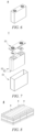
- Fig. 6 illustrates the secondary battery 5 having a square structure as an example.
- the outer package may include a housing 51 and a cover plate 53.
- the housing 51 may include a bottom plate and side plates connected to the bottom plate, and the bottom plate and the side plates enclose to form an accommodating cavity.
- the housing 51 has an opening in communication with the accommodating cavity, and the cover plate 53 can cover the opening to close the accommodating cavity.
- a positive electrode plate, a negative electrode plate and a separator can be subjected to a winding process or a stacking process to form an electrode assembly 52.
- the electrode assembly 52 is encapsulated in the accommodating cavity.
- the electrolyte is infiltrated into the electrode assembly 52.
- the number of the electrode assemblies 52 contained in the secondary battery 5 may be one or more, and can be selected by those skilled in the art according to actual requirements.
- the secondary battery can be assembled into a battery module, and the number of the secondary batteries contained in the battery module may be one or more, and the specific number can be selected by those skilled in the art according to the application and capacity of the battery module.
- Fig. 8 shows a battery module 4 as an example.
- a plurality of secondary batteries 5 may be arranged in sequence in the length direction of the battery module 4.
- the secondary batteries may also be arranged in any other manner.
- the plurality of secondary batteries 5 may be fixed by fasteners.
- the battery module 4 may further comprise a housing with an accommodating space in which and the plurality of secondary batteries 5 are accommodated.
- the above battery module may also be assembled into a battery pack, the number of the battery modules contained in the battery pack may be one or more, and the specific number can be selected by those skilled in the art according to the application and capacity of the battery pack.
- the battery pack 1 may comprise a battery case and a plurality of battery modules 4 provided in the battery case.
- the battery case comprises an upper case 2 and a lower case 3, wherein the upper case 2 can cover the lower case 3 to form a closed space for accommodating the battery modules 4.
- the plurality of battery modules 4 may be arranged inside the battery case in any manner.
- the present application further provides a power consuming device.
- the power consuming device includes at least one of the secondary battery, battery module, or battery pack provided by the present application.
- the secondary battery, battery module or battery pack can be used as a power source of the power consuming device or as an energy storage unit of the power consuming device.
- the power consuming device may include a mobile device (e.g., a mobile phone, a laptop computer, etc.), an electric vehicle (e.g., a pure electric vehicle, a hybrid electric vehicle, a plug-in hybrid electric vehicle, an electric bicycle, an electric scooter, an electric golf cart, an electric truck), an electric train, ship, and satellite, an energy storage system, and the like, but is not limited thereto.
- the secondary battery, battery module or battery pack can be selected according to the usage requirements thereof.
- Fig. 11 shows a power consuming device as an example.
- the power consuming device may be a pure electric vehicle, a hybrid electric vehicle, a plug-in hybrid electric vehicle or the like.
- a battery pack or a battery module may be used.
- the power consuming device may be a mobile phone, a tablet computer, a laptop computer, etc. It is generally required that the power consuming device is thin and light, and the secondary battery may be used as a power source.
- a first positive active material (D50: 8 ⁇ m) as shown in Table 1, a conductive agent SP and a polyvinylidene fluoride (PVDF) as a binder are fully stirred and mixed in a N-methylpyrrolidone (NMP) solvent at a weight ratio of 97:2: 1, and a viscosity is tested to be in the range of 3000-10000 mPa ⁇ s suitable for coating at a rotational speed of 12 rpm, to prepare a first positive electrode slurry.
- NMP N-methylpyrrolidone
- a second positive active material (D50:8 ⁇ m), a conductive agent SP and a polyvinylidene fluoride (PVDF) as a binder are fully stirred and mixed in a N-methylpyrrolidone (NMP) solvent at a weight ratio of 97:2:1, and a viscosity is tested to be in the range of 3000-10000 mPa ⁇ s suitable for coating at a rotational speed of 12 rpm, to prepare a second positive electrode slurry.
- NMP N-methylpyrrolidone
- a first positive electrode slurry is coated on one surface of an aluminum foil as a positive current collector, and a second positive electrode slurry is simultaneously coated on the first positive electrode slurry by a dual-chamber coating apparatus, and the two coating steps are performed synchronously and completed synchronously, thereby forming a first positive film layer and a second positive film layer, wherein the first positive film layer has a weight of 125 g/cm 2 and the second positive film layer has a weight of 125 g/cm 2 .
- the solvent NMP is dried by a coater oven, and then followed by cold pressing, slitting and die cutting procedures, so as to obtain a positive electrode plate.
- a negative active material artificial graphite
- a conductive agent conductive carbon black
- a binder styrene-butadiene rubber (SBR)
- SBR styrene-butadiene rubber
- a thicker sodium carboxymethyl cellulose (CMC)
- the prepared positive electrode plate, the separator, and the negative electrode plate are stacked in sequence so that the separator is positioned between the positive electrode plate and the negative electrode plate for separation, and are wound to obtain a bare battery cell. Subsequently, welding and packaging are performed, and the electrolyte is filled before procedures such as formation, degassing, and final sealing to finally obtain a secondary battery.
- examples 2-26 the same preparation method as in example 1 is used, except that the following changes are made respectively as shown in Table 1: the volume median particle size (D50) of the hollow particles of the first positive active material, the volume median particle size (D50) of the solid particles of the second positive active material, "the ratio of D50 of the hollow particles to the D50 of the solid particles", “the ratio of the number of the hollow particles to the number of all particles", “the ratio of the hollow diameter of the hollow particles to the D50 of the hollow particles”, “the BET of the first positive active material”, “the BET of the second positive active material”, “the weight ratio of the first positive film layer to the second positive film layer", “the thicknesses of the first positive film layer and the second positive film layer”, and “the thickness ratio of the first positive film layer to the second positive film layer”.
- Table 1 the volume median particle size (D50) of the hollow particles of the first positive active material, the volume median particle size (D50) of the solid particles of the second positive active material, “the ratio of D50 of the hollow particles to
- a laser particle size analyzer of Model Malvern 3000 (MasterSizer 3000) is used, with reference to the standard process: GB/T19077-2016/ISO 13320:2009, and the specific test process includes: taking an appropriate amount of the test sample (the sample having a concentration that can ensure a shading of 8%-12%), adding 20 ml of deionized water and externally applying an ultrasonic treatment (53 KHz/120 W) for 5 min at the same time to ensure that the sample is completely dispersed, and then performing tests on the first positive active material and the second positive active material of examples 1-26 and comparative examples 1-3 according to the Standard GB/T19077-2016/ISO 13320:2009.
- the test results are shown in Table 1.
- the hollow diameter of the hollow particles is determined by a cross-sectional morphology electron microscope image, specifically by: selecting a coated plate sample for capturing an image of its cross-sectional topography, then randomly selecting a certain region, and calculating the hollow diameter of all hollow particles in the field of view, wherein the longest diameter is taken as a reference when the hollow diameter is measured.
- the hollow diameter is obtained by averaging the diameters of all hollow particles.
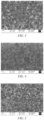
- the positive electrode plates of examples 1-26 and comparative examples 1-3 each are tested with a ZEISS sigma 300 scanning electron microscope, and then tested with reference to the Standard JY/T010-1996 to observe the sample morphology.
- the observations are specifically as follows.
- the positive electrode plate according the present application is formed with a double-layer film layer, in which the first positive film layer is formed at the bottom layer close to the current collector, mainly composed of hollow particles; and the second positive film layer is formed above the first positive film layer close to the separator, mainly composed of solid particles.
- the first positive film layer contains hollow particles in a nearly spherical shape, and the BET of the first positive film layer material is increased by the hollow structure.
- the sample morphologies of the positive electrode plates according to examples 2-26 of the present application are observed in the same manner, and it is observed that the positive electrode plate according to the present application is formed with a double-layer film layer, in which the first positive film layer is formed at the bottom layer close to the current collector, mainly composed of hollow particles; and the second positive film layer is formed above the first positive film layer close to the separator, mainly composed of solid particles.
- the positive electrode plate of comparative example 1 is formed with only a single film layer, that is, only the first positive film layer mainly composed of hollow particles is formed at the bottom layer close to the current collector, and no second positive film layer composed of solid particles is provided.
- the positive electrode plate of comparative example 2 is formed with only a single film layer, that is, only the second positive film layer mainly composed of solid particles is formed at the top layer close to the separator, and no first positive film layer composed of hollow particles is provided.
- the positive electrode plate of comparative example 3 of the present application is also formed with a double-layer film layer, the second positive film layer mainly composed of solid particles is formed at the bottom layer close to the current collector, and the first positive film layer mainly composed of hollow particles is formed above the second positive film layer close to the separator, that is, the double-layer film layer is arranged completely opposite to that of the present application.
- the BETs of the first positive active material and the second positive active material of examples 1-26 and comparative examples 1-3 are tested with a Gemini VII 2390 multi-station automatic specific surface area and porosity analyzer (Micromeritics, U.S.A.). About 7 g of sample is placed in a 9cc long tube with bulbs, degassed at 150°C for 15 minutes, and then placed in the analyzer for testing to obtain BET data. The test results are shown in Table 1.
- the battery cell stands at 25°C for 30 min, is discharged to 3.0 V at a constant current of 0.33 C, stands at 25°C for 1 hour, is charged to 4.3 V at a constant current of 0.33 C, is charged at a constant voltage to a cut-off current of 0.05 C, stands at 25°C for 30 min, is discharged to 3.0 V at a constant current of 0.33 C, and then an initial capacity C0 is obtained.
- the battery cell stands at 25°C for 1 hour, is charged to 4.3 V at a constant current of 0.33 C, is charged at a constant voltage to a cut-off current of 0.05 C, stands at 25°C for 30 min, is discharged at 1 C to 3.0 V, and then a capacity C1 at 1 C is obtained.
- the battery cell stands at 25°C for 1 hour, is charged to 4.3 V at a constant current of 0.33 C, is charged at a constant voltage to a cut-off current of 0.05 C, stands at 25°C for 30 min, is discharged at 2 C to 3.0 V, and then a capacity C2 at 2 C is obtained.
- the capacity retention at 1 C is C1/C0
- the capacity retention at 2 C is C2/C0.
- the battery cell stands at 25°C for 30 min, is discharged to 3.0 V at a constant current of 0.33 C, stands at 25°C for 30 min, is charged to 4.3 V at a constant current of 0.33 C, is charged at a constant voltage to a cut-off current of 0.05 C, stands at 25°C for 30 min, is discharged to 3.0 V at a constant current of 0.33 C, and then a battery cell capacity C is obtained.
- the capacity C0 is obtained by constant capacitance of the battery cell according to the capacity test described in the above (2).
- the battery cell stands at 25°C for 30 min, is charged to 4.3 V at a constant current of 0.33 C0, is charged at a constant voltage to a cut-off current of 0.05 C0, stands at 25°C for 5 min, is discharged to 0.5 C0 at 0.33 C0.
- the battery cell has 50% SOC.
- the battery cell is discharged at a rate of 2 C0 for 30 seconds.
- the voltage of the battery cell before discharging at 2 C0 is V1
- the voltage after discharging for 30 seconds is V2.
- a positive electrode plate having a double-layer electrode film layer formed of a first positive film layer composed of a hollow material and a second positive film layer composed of a solid material as described in the present application the overall rate performance of the lithium ion battery is better, and DCR is lower, while the capacity of the battery is higher. Therefore, a lithium ion battery manufactured by using the positive electrode plate of the present invention has good dynamics performance, and provides a solution for application of a thick electrode plate in a battery.
Landscapes
- Chemical & Material Sciences (AREA)
- Chemical Kinetics & Catalysis (AREA)
- Electrochemistry (AREA)
- General Chemical & Material Sciences (AREA)
- Composite Materials (AREA)
- Engineering & Computer Science (AREA)
- Materials Engineering (AREA)
- Crystallography & Structural Chemistry (AREA)
- Inorganic Chemistry (AREA)
- Manufacturing & Machinery (AREA)
- Battery Electrode And Active Subsutance (AREA)
Applications Claiming Priority (1)
| Application Number | Priority Date | Filing Date | Title |
|---|---|---|---|
| PCT/CN2022/072320 WO2023133881A1 (zh) | 2022-01-17 | 2022-01-17 | 正极极片、二次电池、电池模块、电池包和用电装置 |
Publications (1)
| Publication Number | Publication Date |
|---|---|
| EP4239712A1 true EP4239712A1 (de) | 2023-09-06 |
Family
ID=87279851
Family Applications (1)
| Application Number | Title | Priority Date | Filing Date |
|---|---|---|---|
| EP22879653.8A Pending EP4239712A1 (de) | 2022-01-17 | 2022-01-17 | Positivelektrodenfolie, sekundärbatterie, batteriemodul, batteriepack und elektrische vorrichtung |
Country Status (4)
| Country | Link |
|---|---|
| US (1) | US20230307616A1 (de) |
| EP (1) | EP4239712A1 (de) |
| CN (1) | CN117015865A (de) |
| WO (1) | WO2023133881A1 (de) |
Family Cites Families (4)
| Publication number | Priority date | Publication date | Assignee | Title |
|---|---|---|---|---|
| JP2017157529A (ja) * | 2016-03-04 | 2017-09-07 | セイコーエプソン株式会社 | 電極複合体、電極複合体の製造方法、正極活物質層およびリチウム電池 |
| US20190379043A1 (en) * | 2016-11-25 | 2019-12-12 | Sumitomo Metal Mining Co., Ltd. | Transition metal composite hydroxide and method for producing the same, positive electrode active material for a non-aqueous electrolyte secondary battery and method for producing the same, and non-aqueous electrolyte secondary battery |
| CN109560249A (zh) * | 2018-11-30 | 2019-04-02 | 中国科学院过程工程研究所 | 一种双层结构正极极片、及其制备方法和用途 |
| JP7082938B2 (ja) * | 2018-12-12 | 2022-06-09 | 三洋電機株式会社 | 二次電池 |
-
2022
- 2022-01-17 CN CN202280020064.0A patent/CN117015865A/zh active Pending
- 2022-01-17 WO PCT/CN2022/072320 patent/WO2023133881A1/zh active Application Filing
- 2022-01-17 EP EP22879653.8A patent/EP4239712A1/de active Pending
-
2023
- 2023-05-10 US US18/314,828 patent/US20230307616A1/en active Pending
Also Published As
| Publication number | Publication date |
|---|---|
| CN117015865A (zh) | 2023-11-07 |
| WO2023133881A1 (zh) | 2023-07-20 |
| US20230307616A1 (en) | 2023-09-28 |
Similar Documents
| Publication | Publication Date | Title |
|---|---|---|
| US20220393227A1 (en) | Battery module, battery pack, power consumption apparatus, and manufacturing method and manufacturing device of battery module | |
| WO2021008429A1 (zh) | 二次电池及其相关的电池模块、电池包和装置 | |
| CN115133020B (zh) | 锰酸锂正极活性材料及包含其的正极极片、二次电池、电池模块、电池包和用电装置 | |
| CN111584833A (zh) | 锂二次电池 | |
| US20240030437A1 (en) | Positive electrode slurry and preparation method therefor, positive electrode plate, secondary battery, battery module, battery pack, and electric apparatus | |
| US20230335743A1 (en) | Positive electrode composite material for lithium ion secondary battery, positive electrode and battery | |
| EP4195349B1 (de) | Sekundärbatterie | |
| EP4297139A1 (de) | Sekundärbatterie, batteriemodul, batteriepack und elektrische vorrichtung | |
| EP4239712A1 (de) | Positivelektrodenfolie, sekundärbatterie, batteriemodul, batteriepack und elektrische vorrichtung | |
| KR20230106127A (ko) | 이차 전지 및 이를 포함하는 전기 장치 | |
| JP2023505133A (ja) | 二次電池及び当該二次電池を含む装置 | |
| CN116207240B (zh) | 正极活性材料、正极极片、电池单体、电池及用电装置 | |
| US11791460B2 (en) | Electrode assembly, secondary battery, battery module, battery pack and power consuming device | |
| EP4421889A1 (de) | Positivelektrodenplatte, sekundärbatterie, batteriemodul, batteriepack und stromverbrauchende vorrichtung | |
| US20230352680A1 (en) | Positive electrode composite material for lithium ion secondary battery, positive electrode and battery | |
| EP4243144A1 (de) | Sekundärbatterie | |
| EP4318677A1 (de) | Porenbildungsmittel für sekundärbatterie und herstellungsverfahren dafür, negativelektrodenplatte, elektrodenanordnung und sekundärbatterie | |
| US20220393148A1 (en) | Negative electrode and nonaqueous electrolyte secondary battery including the same | |
| EP4199146A1 (de) | Negative elektrodenplatte, sekundärbatteriemodul, batteriepack und energieverbrauchsvorrichtung | |
| WO2024192669A1 (zh) | 正极极片及其制备方法、电池单体、电池和用电装置 | |
| EP4228079A1 (de) | Batteriepack und stromverbrauchende vorrichtung dafür | |
| EP4376182A1 (de) | Batteriepack und elektrische vorrichtung | |
| CN118648128A (zh) | 一种二次电池及用电装置 | |
| CN116565118A (zh) | 正极极片、二次电池、电池模块、电池包和用电装置 | |
| CN117254129A (zh) | 二次电池和用电装置 |
Legal Events
| Date | Code | Title | Description |
|---|---|---|---|
| STAA | Information on the status of an ep patent application or granted ep patent |
Free format text: STATUS: UNKNOWN |
|
| STAA | Information on the status of an ep patent application or granted ep patent |
Free format text: STATUS: THE INTERNATIONAL PUBLICATION HAS BEEN MADE |
|
| PUAI | Public reference made under article 153(3) epc to a published international application that has entered the european phase |
Free format text: ORIGINAL CODE: 0009012 |
|
| STAA | Information on the status of an ep patent application or granted ep patent |
Free format text: STATUS: REQUEST FOR EXAMINATION WAS MADE |
|
| 17P | Request for examination filed |
Effective date: 20230428 |
|
| AK | Designated contracting states |
Kind code of ref document: A1 Designated state(s): AL AT BE BG CH CY CZ DE DK EE ES FI FR GB GR HR HU IE IS IT LI LT LU LV MC MK MT NL NO PL PT RO RS SE SI SK SM TR |