EP4231069A1 - Dispositif optique d'amortissement - Google Patents
Dispositif optique d'amortissement Download PDFInfo
- Publication number
- EP4231069A1 EP4231069A1 EP22157972.5A EP22157972A EP4231069A1 EP 4231069 A1 EP4231069 A1 EP 4231069A1 EP 22157972 A EP22157972 A EP 22157972A EP 4231069 A1 EP4231069 A1 EP 4231069A1
- Authority
- EP
- European Patent Office
- Prior art keywords
- opening
- damping device
- recess
- radiation
- optical
- Prior art date
- Legal status (The legal status is an assumption and is not a legal conclusion. Google has not performed a legal analysis and makes no representation as to the accuracy of the status listed.)
- Granted
Links
Images
Classifications
-
- G—PHYSICS
- G02—OPTICS
- G02B—OPTICAL ELEMENTS, SYSTEMS OR APPARATUS
- G02B5/00—Optical elements other than lenses
- G02B5/003—Light absorbing elements
-
- G—PHYSICS
- G02—OPTICS
- G02B—OPTICAL ELEMENTS, SYSTEMS OR APPARATUS
- G02B6/00—Light guides; Structural details of arrangements comprising light guides and other optical elements, e.g. couplings
- G02B6/24—Coupling light guides
- G02B6/26—Optical coupling means
- G02B6/264—Optical coupling means with optical elements between opposed fibre ends which perform a function other than beam splitting
- G02B6/266—Optical coupling means with optical elements between opposed fibre ends which perform a function other than beam splitting the optical element being an attenuator
Definitions
- the invention relates to an optical attenuating device and a method for attenuating optical radiation.
- This optical damping device and the method are suitable for damping optical radiation, in particular for damping laser radiation.
- An optical attenuator can be used to reduce the amplitude or level of optical radiation, particularly an optical signal. It is conceivable to use an optical waveguide with a predetermined length as the optical attenuation device, with the length-dependent attenuation of the optical waveguide being known. However, such optical waveguides often have to be specially manufactured and are therefore expensive.
- the invention is based on the object of specifying an optical attenuation device and a method for attenuating optical radiation which can be implemented simply and inexpensively.
- an attenuating device for attenuating optical radiation with a body made of a material that is (substantially) impermeable to the radiation, the body having a recess in the shape of a circular cylinder, a first opening and a second opening, the first opening and the second Opening each form an access to the recess.
- This damping device has a very simple structure and can be manufactured easily and inexpensively become.
- the recess with the shape of a circular cylinder can be produced easily, for example by milling.
- the damping device therefore has a circular-cylindrical recess.
- the first opening and the second opening each pass through the body and open into the recess.
- the recess forms a cavity in the body.
- the recess can form a self-contained cavity in the body, which is connected to the exterior surrounding the body only through the first opening and the second opening.
- the damping device can also have more than two openings, for example three openings. Then the attenuator can operate as an optical splitter at the same time. The second opening is then a first outlet opening and the third opening is a second outlet opening.
- the damping device and the method have the same or similar advantages and can in particular be designed in the same or similar manner.
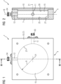
- a damping device 1 is shown, which can also be referred to as a damping device or as a damping element.
- a body 4 of the damping device 1 consists of a material that is optically impermeable to the optical radiation used.
- This body 4 has a can-like part 7 and a lid 10 .
- the cover 10 thereby closes the box-like part 7.
- the cover 10 is detachably connected to the box-like part 7: the cover 10 is screwed to the box-like part 7 by means of four screws (not shown).
- the lid 10 can also be non-detachably connected to the box-like part 7; the lid 10 can be glued or welded to the box-like part 7, for example.
- the body 4, more precisely the can-like part 7, has a first opening 11 and a second opening 12.
- FIG. Furthermore, the body 4 has a recess 15, the recess 15 having the shape of a circular cylinder (circular-cylindrical recess 15).
- the recess 15 has a radius R.
- the height is smaller than the diameter, so it is a flat recess. As a result, the damping device can be constructed in a particularly compact manner.
- the damping device 1 is therefore designed in the form of a disk.
- the recess 15 is enclosed by the body 4 on all sides.
- the body 4 surrounding the recess 15 can consist of a metal or a plastic, for example.
- the body 4 is made of aluminum.
- the recess 15 is only accessible through the first opening 11 and through the second opening 12 for optical radiation.
- the first opening 11 and the second opening 12 are arranged in the box-like part 7 and each formed as a bore-like opening (bore).
- the first opening 11 is an entrance opening for optical radiation
- the second opening 12 is an exit opening for optical radiation.
- the first opening 11 and the second opening 12 lie in a plane 18.
- This plane 18 is perpendicular to a longitudinal axis 21 of the circular-cylindrical recess 15 is arranged.
- the longitudinal axis 18 corresponds to the axis of rotation of the recess 15.
- the first opening 11 and the second opening 12 are at right angles to one another in the plane 18. In other exemplary embodiments, the first opening 11 and the second opening 12 can also be at a different angle to one another on level 18.
- the circular-cylindrical recess 15 is delimited by a base surface 25 , a lateral surface 27 and a top surface 29 of the body 4 .
- the base surface 25 and the lateral surface 27 belong to the box-like part 7 and the top surface 29 belongs to the cover 10 .
- the base surface 25 and the lateral surface 27 are thus formed by the box-like part 7 and the top surface 29 is formed by the lid 10.
- the outer surface 27 of the aluminum body 4 is anodized in the embodiment.
- This anodized lateral surface is advantageously corrosion-resistant and long-term stable.
- the lateral surface can also have a reflective coating. If the body 4 consists of a plastic, for example, then the lateral surface 27 can be coated with a reflective metal, for example.
- a first optical connector 33 is arranged on the end of the first opening 11 facing away from the recess 15 .
- the first optical connector 33 is used to connect a first optical guide medium (e.g. a first optical fiber) to the attenuation device 1.
- a second optical connector 34 is arranged on the end of the second opening 12 facing away from the recess 15, which is used to connect a second optical guiding medium (for example a second optical waveguide) to the damping device 1 is used.
- the first optical connector 33 and the second optical Connector 34 attached to the body 4, more precisely to the box-like part 7 of the body 4, in particular screwed.
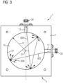
- FIG 3 the method for attenuating optical radiation by means of the attenuation device 1 is shown as a model.
- Incoming optical radiation 303 (here symbolized as an incoming beam 303 as a model) is introduced through the first opening 11 into the recess 15 .
- the optical radiation is reflected multiple times on the surface delimiting the recess 15 (in particular on the lateral surface 27 of the recess 15).
- reflection points 306 are shown only symbolically. In practice, many more reflections occur, so that the incoming radiation 303 is distributed almost uniformly over the entire lateral surface 27.
- optical coupling loss can also occur if the second optical guide medium (for example the second optical waveguide) is connected to the second opening. If the outgoing optical radiation 309 is coupled into the second conducting medium, then the coupling loss occur, which is added to the damping of the damping device.
- the second optical guide medium for example the second optical waveguide
- the damping device 1 described as an example has only the first opening and the second opening. In other exemplary embodiments, however, the damping device can also have more than two openings, for example the damping device can also have a third opening.
- the second opening is then a first outlet opening and the third opening is then a second outlet opening.
- the attenuation device can then in particular also work as an optical splitter.
- the damping device can therefore generally have an entry opening for optical radiation and one or more exit openings for optical radiation.
- the openings can be distributed in the plane 18 along the circumference of the circular-cylindrical recess 15 .
- the third opening can in particular be opposite the second opening 12 , that is to say offset by 180 degrees with respect to the second opening 12 .
- the first opening is then perpendicular to the second opening 12 and perpendicular to the third opening in the plane 18.
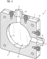
- figure 4 shows the damping device 1 in a three-dimensional sectional view.
- the first opening 11 and the second opening 12, which form the entry opening and the exit opening for the optical radiation, can be clearly seen.
- a damping device which uses multiple reflections within a recess, in particular within a closed geometry, in order to achieve a damping effect for optical radiation.
- the recess can in particular have the shape of a (flat) circular cylinder.
- An aluminum block can be used as the body, in which the recess is made (for example by milling).
- the radiated light power is distributed by the multiple reflections on the perimeter of the recess.
- the damping device can be manufactured simply and inexpensively and has a compact/space-saving design.
Landscapes
- Physics & Mathematics (AREA)
- General Physics & Mathematics (AREA)
- Optics & Photonics (AREA)
- Vibration Prevention Devices (AREA)
- Optical Elements Other Than Lenses (AREA)
Priority Applications (1)
| Application Number | Priority Date | Filing Date | Title |
|---|---|---|---|
| EP22157972.5A EP4231069B1 (fr) | 2022-02-22 | 2022-02-22 | Dispositif optique d'amortissement |
Applications Claiming Priority (1)
| Application Number | Priority Date | Filing Date | Title |
|---|---|---|---|
| EP22157972.5A EP4231069B1 (fr) | 2022-02-22 | 2022-02-22 | Dispositif optique d'amortissement |
Publications (3)
| Publication Number | Publication Date |
|---|---|
| EP4231069A1 true EP4231069A1 (fr) | 2023-08-23 |
| EP4231069B1 EP4231069B1 (fr) | 2025-12-24 |
| EP4231069C0 EP4231069C0 (fr) | 2025-12-24 |
Family
ID=80447631
Family Applications (1)
| Application Number | Title | Priority Date | Filing Date |
|---|---|---|---|
| EP22157972.5A Active EP4231069B1 (fr) | 2022-02-22 | 2022-02-22 | Dispositif optique d'amortissement |
Country Status (1)
| Country | Link |
|---|---|
| EP (1) | EP4231069B1 (fr) |
Citations (3)
| Publication number | Priority date | Publication date | Assignee | Title |
|---|---|---|---|---|
| DE3027590A1 (de) * | 1980-07-21 | 1982-02-11 | Siemens AG, 1000 Berlin und 8000 München | Absorber fuer laserstrahlung hoher leistung |
| US4583860A (en) * | 1983-11-30 | 1986-04-22 | The United States Of America As Represented By The Administrator Of The National Aeronautics And Space Administration | Optical multiple sample vacuum integrating sphere |
| WO2016138951A1 (fr) * | 2015-03-04 | 2016-09-09 | Trumpf Lasersystems For Semiconductor Manufacturing Gmbh | Piège à faisceau, dispositif de guidage de faisceau, dispositif de production de rayonnement euv et procédé d'absorption d'un faisceau |
-
2022
- 2022-02-22 EP EP22157972.5A patent/EP4231069B1/fr active Active
Patent Citations (3)
| Publication number | Priority date | Publication date | Assignee | Title |
|---|---|---|---|---|
| DE3027590A1 (de) * | 1980-07-21 | 1982-02-11 | Siemens AG, 1000 Berlin und 8000 München | Absorber fuer laserstrahlung hoher leistung |
| US4583860A (en) * | 1983-11-30 | 1986-04-22 | The United States Of America As Represented By The Administrator Of The National Aeronautics And Space Administration | Optical multiple sample vacuum integrating sphere |
| WO2016138951A1 (fr) * | 2015-03-04 | 2016-09-09 | Trumpf Lasersystems For Semiconductor Manufacturing Gmbh | Piège à faisceau, dispositif de guidage de faisceau, dispositif de production de rayonnement euv et procédé d'absorption d'un faisceau |
Also Published As
| Publication number | Publication date |
|---|---|
| EP4231069B1 (fr) | 2025-12-24 |
| EP4231069C0 (fr) | 2025-12-24 |
Similar Documents
| Publication | Publication Date | Title |
|---|---|---|
| DE69207179T2 (de) | Optoelektronisches bauteil | |
| DE68921207T2 (de) | Verfahren zur Herstellung eines faseroptischen Steckers. | |
| DE3012775C2 (de) | Übergang zwischen zwei Monomodelichtleitern | |
| DE2938649A1 (de) | Vorrichtung und verfahren zur signaluebertragung in lichtleitern | |
| DE2224728A1 (de) | Optischer Wellenleiter | |
| DE2529073C2 (de) | Koppelelement für Glasfaserlichtleiter | |
| DE68916928T2 (de) | Optisches Element. | |
| EP0344645B1 (fr) | Appareil de mesure de réflexion | |
| DE3786217T2 (de) | Verbinder für optische Fasern. | |
| DE19711121A1 (de) | Verzweigende Lichtwellenleiteranordnung | |
| DE1149419B (de) | Vorrichtung zur Verbindung eines Hohlleiters von kreisfoermigem Querschnitt mit zwei im Querschnitt rechteckigen Hohlleitern | |
| DE3789908T2 (de) | Vorrichtung und Verfahren zur gesteuerten Emission des Lichts aus einem Prismenlichtwellenleiter. | |
| EP0315270A2 (fr) | Elément optique à portes multiples avec un modulateur acousto-optique | |
| EP4231069A1 (fr) | Dispositif optique d'amortissement | |
| DE3431605C2 (fr) | ||
| DE10033785C2 (de) | Vorrichtung zum Einkoppeln von Laserstrahlen in eine Lichtleitfaser | |
| DE102022102057A1 (de) | Lichtwellenleiterstecker sowie Lichtwellenleiterverbinder mit einem solchen | |
| DE69914511T2 (de) | Optisches abbildungssystem | |
| DE102023118609B4 (de) | Multilichtwellenleiterstecker sowie Lichtwellenleiterverbinder mit einem solchen | |
| DE3908530C1 (fr) | ||
| DE3542614A1 (de) | Verfahren zur daempfung von optischen substratwellen in einem integriert optischen bauelement | |
| WO1990007132A1 (fr) | Piege a lumiere exempt de retrodiffusion | |
| DE69413703T2 (de) | Inspektionsvorrichtung für optische wellenleiter | |
| DE102013209473B4 (de) | Lichtleiter | |
| DE102011080328B4 (de) | Wellenleiter und Verbindungselement |
Legal Events
| Date | Code | Title | Description |
|---|---|---|---|
| PUAI | Public reference made under article 153(3) epc to a published international application that has entered the european phase |
Free format text: ORIGINAL CODE: 0009012 |
|
| STAA | Information on the status of an ep patent application or granted ep patent |
Free format text: STATUS: THE APPLICATION HAS BEEN PUBLISHED |
|
| STAA | Information on the status of an ep patent application or granted ep patent |
Free format text: STATUS: REQUEST FOR EXAMINATION WAS MADE |
|
| AK | Designated contracting states |
Kind code of ref document: A1 Designated state(s): AL AT BE BG CH CY CZ DE DK EE ES FI FR GB GR HR HU IE IS IT LI LT LU LV MC MK MT NL NO PL PT RO RS SE SI SK SM TR |
|
| 17P | Request for examination filed |
Effective date: 20230727 |
|
| RBV | Designated contracting states (corrected) |
Designated state(s): AL AT BE BG CH CY CZ DE DK EE ES FI FR GB GR HR HU IE IS IT LI LT LU LV MC MK MT NL NO PL PT RO RS SE SI SK SM TR |
|
| GRAP | Despatch of communication of intention to grant a patent |
Free format text: ORIGINAL CODE: EPIDOSNIGR1 |
|
| STAA | Information on the status of an ep patent application or granted ep patent |
Free format text: STATUS: GRANT OF PATENT IS INTENDED |
|
| INTG | Intention to grant announced |
Effective date: 20250808 |
|
| GRAS | Grant fee paid |
Free format text: ORIGINAL CODE: EPIDOSNIGR3 |
|
| GRAA | (expected) grant |
Free format text: ORIGINAL CODE: 0009210 |
|
| STAA | Information on the status of an ep patent application or granted ep patent |
Free format text: STATUS: THE PATENT HAS BEEN GRANTED |
|
| AK | Designated contracting states |
Kind code of ref document: B1 Designated state(s): AL AT BE BG CH CY CZ DE DK EE ES FI FR GB GR HR HU IE IS IT LI LT LU LV MC MK MT NL NO PL PT RO RS SE SI SK SM TR |
|
| REG | Reference to a national code |
Ref country code: CH Ref legal event code: F10 Free format text: ST27 STATUS EVENT CODE: U-0-0-F10-F00 (AS PROVIDED BY THE NATIONAL OFFICE) Effective date: 20251224 Ref country code: GB Ref legal event code: FG4D Free format text: NOT ENGLISH |
|
| REG | Reference to a national code |
Ref country code: DE Ref legal event code: R096 Ref document number: 502022006519 Country of ref document: DE |
|
| U01 | Request for unitary effect filed |
Effective date: 20251224 |
|
| U07 | Unitary effect registered |
Designated state(s): AT BE BG DE DK EE FI FR IT LT LU LV MT NL PT RO SE SI Effective date: 20260107 |