EP4231069A1 - Optical damping device - Google Patents
Optical damping device Download PDFInfo
- Publication number
- EP4231069A1 EP4231069A1 EP22157972.5A EP22157972A EP4231069A1 EP 4231069 A1 EP4231069 A1 EP 4231069A1 EP 22157972 A EP22157972 A EP 22157972A EP 4231069 A1 EP4231069 A1 EP 4231069A1
- Authority
- EP
- European Patent Office
- Prior art keywords
- opening
- damping device
- recess
- radiation
- optical
- Prior art date
- Legal status (The legal status is an assumption and is not a legal conclusion. Google has not performed a legal analysis and makes no representation as to the accuracy of the status listed.)
- Pending
Links
Images
Classifications
-
- G—PHYSICS
- G02—OPTICS
- G02B—OPTICAL ELEMENTS, SYSTEMS OR APPARATUS
- G02B5/00—Optical elements other than lenses
- G02B5/003—Light absorbing elements
-
- G—PHYSICS
- G02—OPTICS
- G02B—OPTICAL ELEMENTS, SYSTEMS OR APPARATUS
- G02B6/00—Light guides; Structural details of arrangements comprising light guides and other optical elements, e.g. couplings
- G02B6/24—Coupling light guides
- G02B6/26—Optical coupling means
- G02B6/264—Optical coupling means with optical elements between opposed fibre ends which perform a function other than beam splitting
- G02B6/266—Optical coupling means with optical elements between opposed fibre ends which perform a function other than beam splitting the optical element being an attenuator
Definitions
- the invention relates to an optical attenuating device and a method for attenuating optical radiation.
- This optical damping device and the method are suitable for damping optical radiation, in particular for damping laser radiation.
- An optical attenuator can be used to reduce the amplitude or level of optical radiation, particularly an optical signal. It is conceivable to use an optical waveguide with a predetermined length as the optical attenuation device, with the length-dependent attenuation of the optical waveguide being known. However, such optical waveguides often have to be specially manufactured and are therefore expensive.
- the invention is based on the object of specifying an optical attenuation device and a method for attenuating optical radiation which can be implemented simply and inexpensively.
- an attenuating device for attenuating optical radiation with a body made of a material that is (substantially) impermeable to the radiation, the body having a recess in the shape of a circular cylinder, a first opening and a second opening, the first opening and the second Opening each form an access to the recess.
- This damping device has a very simple structure and can be manufactured easily and inexpensively become.
- the recess with the shape of a circular cylinder can be produced easily, for example by milling.
- the damping device therefore has a circular-cylindrical recess.
- the first opening and the second opening each pass through the body and open into the recess.
- the recess forms a cavity in the body.
- the recess can form a self-contained cavity in the body, which is connected to the exterior surrounding the body only through the first opening and the second opening.
- the damping device can also have more than two openings, for example three openings. Then the attenuator can operate as an optical splitter at the same time. The second opening is then a first outlet opening and the third opening is a second outlet opening.
- the damping device and the method have the same or similar advantages and can in particular be designed in the same or similar manner.
- a damping device 1 is shown, which can also be referred to as a damping device or as a damping element.
- a body 4 of the damping device 1 consists of a material that is optically impermeable to the optical radiation used.
- This body 4 has a can-like part 7 and a lid 10 .
- the cover 10 thereby closes the box-like part 7.
- the cover 10 is detachably connected to the box-like part 7: the cover 10 is screwed to the box-like part 7 by means of four screws (not shown).
- the lid 10 can also be non-detachably connected to the box-like part 7; the lid 10 can be glued or welded to the box-like part 7, for example.
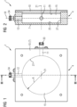
- the body 4, more precisely the can-like part 7, has a first opening 11 and a second opening 12.
- FIG. Furthermore, the body 4 has a recess 15, the recess 15 having the shape of a circular cylinder (circular-cylindrical recess 15).
- the recess 15 has a radius R.
- the height is smaller than the diameter, so it is a flat recess. As a result, the damping device can be constructed in a particularly compact manner.
- the damping device 1 is therefore designed in the form of a disk.
- the recess 15 is enclosed by the body 4 on all sides.
- the body 4 surrounding the recess 15 can consist of a metal or a plastic, for example.
- the body 4 is made of aluminum.
- the recess 15 is only accessible through the first opening 11 and through the second opening 12 for optical radiation.
- the first opening 11 and the second opening 12 are arranged in the box-like part 7 and each formed as a bore-like opening (bore).
- the first opening 11 is an entrance opening for optical radiation
- the second opening 12 is an exit opening for optical radiation.
- the first opening 11 and the second opening 12 lie in a plane 18.
- This plane 18 is perpendicular to a longitudinal axis 21 of the circular-cylindrical recess 15 is arranged.
- the longitudinal axis 18 corresponds to the axis of rotation of the recess 15.
- the first opening 11 and the second opening 12 are at right angles to one another in the plane 18. In other exemplary embodiments, the first opening 11 and the second opening 12 can also be at a different angle to one another on level 18.
- the circular-cylindrical recess 15 is delimited by a base surface 25 , a lateral surface 27 and a top surface 29 of the body 4 .
- the base surface 25 and the lateral surface 27 belong to the box-like part 7 and the top surface 29 belongs to the cover 10 .
- the base surface 25 and the lateral surface 27 are thus formed by the box-like part 7 and the top surface 29 is formed by the lid 10.
- the outer surface 27 of the aluminum body 4 is anodized in the embodiment.
- This anodized lateral surface is advantageously corrosion-resistant and long-term stable.
- the lateral surface can also have a reflective coating. If the body 4 consists of a plastic, for example, then the lateral surface 27 can be coated with a reflective metal, for example.
- a first optical connector 33 is arranged on the end of the first opening 11 facing away from the recess 15 .
- the first optical connector 33 is used to connect a first optical guide medium (e.g. a first optical fiber) to the attenuation device 1.
- a second optical connector 34 is arranged on the end of the second opening 12 facing away from the recess 15, which is used to connect a second optical guiding medium (for example a second optical waveguide) to the damping device 1 is used.
- the first optical connector 33 and the second optical Connector 34 attached to the body 4, more precisely to the box-like part 7 of the body 4, in particular screwed.
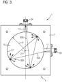
- FIG 3 the method for attenuating optical radiation by means of the attenuation device 1 is shown as a model.
- Incoming optical radiation 303 (here symbolized as an incoming beam 303 as a model) is introduced through the first opening 11 into the recess 15 .
- the optical radiation is reflected multiple times on the surface delimiting the recess 15 (in particular on the lateral surface 27 of the recess 15).
- reflection points 306 are shown only symbolically. In practice, many more reflections occur, so that the incoming radiation 303 is distributed almost uniformly over the entire lateral surface 27.
- optical coupling loss can also occur if the second optical guide medium (for example the second optical waveguide) is connected to the second opening. If the outgoing optical radiation 309 is coupled into the second conducting medium, then the coupling loss occur, which is added to the damping of the damping device.
- the second optical guide medium for example the second optical waveguide
- the damping device 1 described as an example has only the first opening and the second opening. In other exemplary embodiments, however, the damping device can also have more than two openings, for example the damping device can also have a third opening.
- the second opening is then a first outlet opening and the third opening is then a second outlet opening.
- the attenuation device can then in particular also work as an optical splitter.
- the damping device can therefore generally have an entry opening for optical radiation and one or more exit openings for optical radiation.
- the openings can be distributed in the plane 18 along the circumference of the circular-cylindrical recess 15 .
- the third opening can in particular be opposite the second opening 12 , that is to say offset by 180 degrees with respect to the second opening 12 .
- the first opening is then perpendicular to the second opening 12 and perpendicular to the third opening in the plane 18.
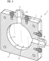
- figure 4 shows the damping device 1 in a three-dimensional sectional view.
- the first opening 11 and the second opening 12, which form the entry opening and the exit opening for the optical radiation, can be clearly seen.
- a damping device which uses multiple reflections within a recess, in particular within a closed geometry, in order to achieve a damping effect for optical radiation.
- the recess can in particular have the shape of a (flat) circular cylinder.
- An aluminum block can be used as the body, in which the recess is made (for example by milling).
- the radiated light power is distributed by the multiple reflections on the perimeter of the recess.
- the damping device can be manufactured simply and inexpensively and has a compact/space-saving design.
Abstract
Eine Dämpfungseinrichtung (1) zum Dämpfen optischer Strahlung hat einen Körper (4) aus einem für die Strahlung im Wesentlichen undurchlässigen Material, wobei der Körper (4) eine Ausnehmung (15) mit der Form eines Kreiszylinders, eine erste Öffnung (11) und eine zweite Öffnung (12) aufweist. Die erste Öffnung (11) und die zweite Öffnung (12) bilden jeweils einen Zugang zu der Ausnehmung (15).An attenuating device (1) for attenuating optical radiation has a body (4) made of a material which is essentially impermeable to the radiation, the body (4) having a recess (15) with the shape of a circular cylinder, a first opening (11) and a second opening (12). The first opening (11) and the second opening (12) each form an access to the recess (15).
Description
Die Erfindung betrifft eine optische Dämpfungseinrichtung und ein Verfahren zum Dämpfen von optischer Strahlung. Diese optische Dämpfungseinrichtung und das Verfahren sind geeignet zur Dämpfung von optischer Strahlung, insbesondere zur Dämpfung von Laserstrahlung.The invention relates to an optical attenuating device and a method for attenuating optical radiation. This optical damping device and the method are suitable for damping optical radiation, in particular for damping laser radiation.
Eine optische Dämpfungseinrichtung kann eingesetzt werden, um die Amplitude oder den Pegel einer optischen Strahlung, insbesondere eines optischen Signals, zu verringern. Dabei ist es denkbar, als optische Dämpfungseinrichtung einen Lichtwellenleiter mit einer vorbestimmten Länge einzusetzen, wobei die längenabhängige Dämpfung des Lichtwellenleiters bekannt ist. Solche Lichtwellenleiter müssen jedoch oftmals speziell angefertigt werden und sind daher teuer.An optical attenuator can be used to reduce the amplitude or level of optical radiation, particularly an optical signal. It is conceivable to use an optical waveguide with a predetermined length as the optical attenuation device, with the length-dependent attenuation of the optical waveguide being known. However, such optical waveguides often have to be specially manufactured and are therefore expensive.
Der Erfindung liegt die Aufgabe zugrunde, eine optische Dämpfungseinrichtung und ein Verfahren zum Dämpfen von optischer Strahlung anzugeben, die einfach und kostengünstig realisiert werden können.The invention is based on the object of specifying an optical attenuation device and a method for attenuating optical radiation which can be implemented simply and inexpensively.
Diese Aufgabe wird erfindungsgemäß gelöst durch eine Dämpfungseinrichtung und durch ein Verfahren nach den unabhängigen Patentansprüchen. Vorteilhafte Ausgestaltungen der Dämpfungseinrichtung sind in den abhängigen Patentansprüchen angegeben.This object is achieved according to the invention by a damping device and by a method according to the independent patent claims. Advantageous configurations of the damping device are specified in the dependent patent claims.
Offenbart wird eine Dämpfungseinrichtung zum Dämpfen optischer Strahlung mit einem Körper aus einem für die Strahlung (im Wesentlichen) undurchlässigen Material, wobei der Körper eine Ausnehmung mit der Form eines Kreiszylinders, eine erste Öffnung und eine zweite Öffnung aufweist, wobei die erste Öffnung und die zweite Öffnung jeweils einen Zugang zu der Ausnehmung bilden. Diese Dämpfungseinrichtung ist sehr einfach aufgebaut und kann einfach und kostengünstig hergestellt werden. Insbesondere kann die Ausnehmung mit der Form des Kreiszylinders einfach hergestellt werden, zum Beispiel durch Fräsen.Disclosed is an attenuating device for attenuating optical radiation with a body made of a material that is (substantially) impermeable to the radiation, the body having a recess in the shape of a circular cylinder, a first opening and a second opening, the first opening and the second Opening each form an access to the recess. This damping device has a very simple structure and can be manufactured easily and inexpensively become. In particular, the recess with the shape of a circular cylinder can be produced easily, for example by milling.
Die Dämpfungseinrichtung weist also eine kreiszylinderförmige Ausnehmung auf. Die erste Öffnung und die zweite Öffnung durchgreifen jeweils den Körper und münden in die Ausnehmung. Die Ausnehmung bildet einen Hohlraum in dem Körper. Insbesondere kann die Ausnehmung einen in sich geschlossenen Hohlraum in dem Körper bilden, der nur durch die erste Öffnung und die zweite Öffnung mit dem den Körper umgebenden Außenraum verbunden ist.The damping device therefore has a circular-cylindrical recess. The first opening and the second opening each pass through the body and open into the recess. The recess forms a cavity in the body. In particular, the recess can form a self-contained cavity in the body, which is connected to the exterior surrounding the body only through the first opening and the second opening.
Die Dämpfungseinrichtung kann so ausgestaltet sein, dass
- die erste Öffnung und die zweite Öffnung jeweils als eine bohrungsartige Öffnung (insbesondere eine Bohrung) ausgebildet sind. Die bohrungsartigen Öffnungen in dem Körper sind einfach herstellbar.
- the first opening and the second opening are each formed as a bore-like opening (in particular a bore). The bore-like openings in the body are easy to produce.
Die Dämpfungseinrichtung kann so ausgestaltet sein, dass
- die erste Öffnung und die zweite Öffnung in einer Ebene liegen, wobei die Ebene senkrecht (orthogonal) zu der Längsachse der (kreiszylinderförmigen) Ausnehmung angeordnet ist. Dadurch kann die Dämpfungseinrichtung sehr kompakt realisiert werden.
- the first opening and the second opening lie in one plane, the plane being arranged perpendicularly (orthogonally) to the longitudinal axis of the (circular-cylindrical) recess. As a result, the damping device can be made very compact.
Die Dämpfungseinrichtung kann so ausgestaltet sein, dass
- die erste Öffnung und die zweite Öffnung rechtwinklig zueinander in der Ebene liegen. Es sind aber auch andere Winkelbeziehungen zwischen der ersten Öffnung und der zweiten Öffnung möglich.
- the first opening and the second opening are perpendicular to each other in the plane. However, other angular relationships between the first opening and the second opening are also possible.
Die Dämpfungseinrichtung kann so ausgestaltet sein, dass
- die Ausnehmung allseitig von dem Körper umschlossen ist.
- the recess is surrounded on all sides by the body.
Die Dämpfungseinrichtung kann so ausgestaltet sein, dass
- die Ausnehmung (ausschließlich) durch die erste Öffnung und die zweite Öffnung für optische Strahlung zugänglich ist.
- the recess is (exclusively) accessible through the first opening and the second opening for optical radiation.
Die Dämpfungseinrichtung kann so ausgestaltet sein, dass
- die erste Öffnung eine Eintrittsöffnung für optische Strahlung und die zweite Öffnung eine Austrittsöffnung für optische Strahlung ist.
- the first opening is an entrance opening for optical radiation and the second opening is an exit opening for optical radiation.
Die Dämpfungseinrichtung kann so ausgestaltet sein, dass
- der Körper einen dosenartigen Teil (Dose) und einen Deckel aufweist, wobei der Deckel den dosenartigen Teil verschließt.
- the body has a can-like part (can) and a lid, the lid closing the can-like part.
Die Dämpfungseinrichtung kann so ausgestaltet sein, dass
- der Deckel lösbar mit dem dosenartigen Teil verbunden ist. Eine lösbare Verbindung ist deshalb vorteilhaft, weil dadurch bei Bedarf der Deckel einfach geöffnet werden kann (beispielsweise zum Reinigen der Ausnehmung). Der Deckel kann insbesondere mit dem dosenartigen Teil verschraubt sein. Alternativ kann der Deckel aber auch nichtlösbar mit dem dosenartigen Teil verbunden sein; der Deckel kann beispielsweise mit dem dosenartigen Teil verschweißt oder verklebt sein.
- the lid is detachably connected to the box-like part. A detachable connection is advantageous because it allows the cover to be easily opened if necessary (for example to clean the recess). In particular, the lid can be screwed to the box-like part. Alternatively, the lid can also be non-detachably connected to the box-like part; the lid can, for example, be welded or glued to the can-like part.
Die Dämpfungseinrichtung kann so ausgestaltet sein, dass
- die erste Öffnung und die zweite Öffnung in dem dosenartigen Teil angeordnet sind.
- the first opening and the second opening are arranged in the can-like part.
Die Dämpfungseinrichtung kann so ausgestaltet sein, dass
- die (kreiszylinderförmige) Ausnehmung von einer Grundfläche, einer Mantelfläche und einer Deckfläche (des Körpers) begrenzt ist.
- the (circular-cylindrical) recess is delimited by a base area, a lateral area and a top area (of the body).
Die Dämpfungseinrichtung kann insbesondere so ausgestaltet sein, dass
- die Grundfläche und die Mantelfläche dem dosenartigen Teil zugehörig sind und die Deckfläche dem Deckel zugehörig ist.
- the base area and the lateral area belong to the can-like part and the top area belongs to the lid.
Die Dämpfungseinrichtung kann so ausgestaltet sein, dass
- die Mantelfläche reflektierend beschichtet oder eloxiert ist. Der Körper kann insbesondere aus Aluminium bestehen, dann kann die Mantelfläche eloxiert sein. Durch die Eloxierung wird die Langzeitstabilität der Dämpfungseinrichtung verbessert, weil durch die Eloxierung eine unkontrollierte Korrosion der Mantelfläche vermieden oder zumindest reduziert wird. Wenn der Körper aus einem anderen Material besteht (beispielsweise aus einem anderen Metall oder aus einem Kunststoff), dann kann die Mantelfläche insbesondere reflektierend beschichtet sein. Durch die Beschichtung werden die Reflexionseigenschaften verbessert.
- the lateral surface is reflectively coated or anodized. The body can consist in particular of aluminum, in which case the lateral surface can be anodized. By anodizing the long-term stability of the damping device is improved because uncontrolled corrosion of the lateral surface is avoided or at least reduced by the anodization. If the body consists of a different material (for example a different metal or a plastic), then the lateral surface can have a reflective coating in particular. The coating improves the reflection properties.
Die Dämpfungseinrichtung kann so ausgestaltet sein, dass
- die optische Dämpfung der Dämpfungseinrichtung (im Wesentlichen) dem Verhältnis aus der freien Querschnittsfläche der zweiten Öffnung (also der Austrittsöffnung) und der Mantelfläche entspricht. Durch die Wahl dieses Verhältnisses kann also die Dämpfung in einem weiten Bereich gewählt werden.
- the optical damping of the damping device corresponds (essentially) to the ratio of the free cross-sectional area of the second opening (ie the outlet opening) and the lateral surface. By choosing this ratio, the damping can be chosen within a wide range.
Die Dämpfungseinrichtung kann auch mehr als zwei Öffnungen aufweisen, zum Beispiel drei Öffnungen. Dann kann die Dämpfungseinrichtung gleichzeitig als ein optischer Verzweiger arbeiten. Die zweite Öffnung ist dann eine erste Austrittsöffnung und die dritte Öffnung ist eine zweite Austrittsöffnung.The damping device can also have more than two openings, for example three openings. Then the attenuator can operate as an optical splitter at the same time. The second opening is then a first outlet opening and the third opening is a second outlet opening.
Offenbart wird weiterhin ein Verfahren zum Dämpfen von optischer Strahlung mittels einer Dämpfungseinrichtung mit einem Körper aus einem für die Strahlung (im Wesentlichen) undurchlässigen Material, wobei der Körper eine Ausnehmung mit der Form eines Kreiszylinders, eine erste Öffnung und eine zweite Öffnung aufweist, wobei die erste Öffnung und die zweite Öffnung jeweils einen Zugang zu der Ausnehmung bilden, wobei bei dem Verfahren
- optische Strahlung durch die erste Öffnung (als eingehende Strahlung) in die Ausnehmung eingeleitet wird,
- die Strahlung an einer die Ausnehmung begrenzenden Fläche (hier: insbesondere an der Mantelfläche der Ausnehmung) vielfach reflektiert wird, und
- nur derjenige Anteil der (eingehenden) Strahlung, der auf die zweite Öffnung reflektiert wird, als ausgehende Strahlung aus dem Körper ausgeleitet wird.
- optical radiation is introduced into the recess through the first opening (as incoming radiation),
- the radiation is reflected multiple times on a surface delimiting the recess (here: in particular on the lateral surface of the recess), and
- only that part of the (incoming) radiation that is reflected onto the second opening is led out of the body as outgoing radiation.
Das Verfahren kann so ablaufen, dass
- die erste Öffnung und die zweite Öffnung in einer Ebene liegen, wobei die Ebene senkrecht (orthogonal) zu der Längsachse der (kreiszylinderförmigen) Ausnehmung angeordnet ist.
- the first opening and the second opening lie in one plane, the plane being arranged perpendicularly (orthogonally) to the longitudinal axis of the (circular-cylindrical) recess.
Die Dämpfungseinrichtung und das Verfahren weisen gleiche oder gleichartige Vorteile auf und können insbesondere gleich oder gleichartig ausgestaltet sein.The damping device and the method have the same or similar advantages and can in particular be designed in the same or similar manner.
Im Folgenden wird die Erfindung anhand von Ausführungsbeispielen näher erläutert. Gleiche Bezugszeichen verweisen dabei auf gleiche oder gleich wirkende Elemente. Dazu ist in
Figur 1- ein Ausführungsbeispiel einer Dämpfungseinrichtung in einer Ansicht von vorn, in
- Figur 2
- die Dämpfungseinrichtung in einer Ansicht von der Seite im Schnitt, in
- Figur 3
- die Dämpfungseinrichtung mit einem beispielhaften Strahlenverlauf, und in
- Figur 4
- eine dreidimensionale Schnittdarstellung der Dämpfungseinrichtung
- figure 1
- an embodiment of a damping device in a front view, in
- figure 2
- the damping device in a view from the side in section, in
- figure 3
- the attenuator with an exemplary beam path, and in
- figure 4
- a three-dimensional sectional view of the damping device
In den
Ein Körper 4 der Dämpfungseinrichtung 1 besteht aus einem für die verwendete optische Strahlung optisch undurchlässigen Material. Dieser Körper 4 weist einen dosenartigen Teil 7 und einen Deckel 10 auf. Der Deckel 10 verschließt dabei den dosenartigen Teil 7. Im Ausführungsbeispiel ist der Deckel 10 lösbar mit dem dosenartigen Teil 7 verbunden: der Deckel 10 ist mittels vier nicht dargestellter Schrauben mit dem dosenartigen Teil 7 verschraubt. In anderen Ausführungsbeispielen kann der Deckel 10 aber auch nichtlösbar mit dem dosenartigen Teil 7 verbunden sein, der Deckel 10 kann beispielsweise mit dem dosenartigen Teil 7 verklebt oder verschweißt sein.A body 4 of the damping
Der Körper 4, genauer gesagt der dosenartige Teil 7, weist eine erste Öffnung 11 und eine zweite Öffnung 12 auf. Weiterhin weist der Körper 4 eine Ausnehmung 15 auf, wobei die Ausnehmung 15 die Form eines Kreiszylinders hat (kreiszylinderförmige Ausnehmung 15). Die Ausnehmung 15 weist einen Radius R auf. Bei der kreiszylinderförmigen Ausnehmung 15 ist insbesondere die Höhe kleiner als der Durchmesser, es handelt sich also um eine flache Ausnehmung. Dadurch kann die Dämpfungseinrichtung besonders kompakt aufgebaut werden.The body 4, more precisely the can-
Die Dämpfungseinrichtung 1 ist also scheibenförmig ausgestaltet. Die Ausnehmung 15 ist dabei allseitig von dem Körper 4 umschlossen. Der die Ausnehmung 15 umgebende Körper 4 kann beispielsweise aus einem Metall oder aus einem Kunststoff bestehen. Im Ausführungsbeispiel besteht der Körper 4 aus Aluminium. Die Ausnehmung 15 ist ausschließlich durch die erste Öffnung 11 und durch die zweite Öffnung 12 für optische Strahlung zugänglich.The damping
Die erste Öffnung 11 und die zweite Öffnung 12 sind in dem dosenartigen Teil 7 angeordnet und jeweils als eine bohrungsartige Öffnung (Bohrung) ausgebildet. Die erste Öffnung 11 ist eine Eintrittsöffnung für optische Strahlung, die zweite Öffnung 12 ist eine Austrittsöffnung für optische Strahlung. Die erste Öffnung 11 und die zweite Öffnung 12 liegen in einer Ebene 18. Diese Ebene 18 ist senkrecht zu einer Längsachse 21 der kreiszylinderförmigen Ausnehmung 15 angeordnet. Die Längsachse 18 entspricht dabei der Rotationsachse der Ausnehmung 15. Dabei liegen die erste Öffnung 11 und der zweite Öffnung 12 rechtwinklig zueinander in der Ebene 18. In anderen Ausführungsbeispielen können die erste Öffnung 11 und die zweite Öffnung 12 aber auch in einem anderen Winkel zueinander in der Ebene 18 liegen.The
Die kreiszylinderförmige Ausnehmung 15 ist von einer Grundfläche 25, einer Mantelfläche 27 und einer Deckfläche 29 des Körpers 4 begrenzt. Dabei ist die Grundfläche 25 und die Mantelfläche 27 dem dosenartigen Teil 7 zugehörig und die Deckfläche 29 ist dem Deckel 10 zugehörig. Die Grundfläche 25 und die Mantelfläche 27 werden also von dem dosenartigen Teil 7 gebildet und die Deckfläche 29 wird von dem Deckel 10 gebildet.The circular-
Die Mantelfläche 27 des aus Aluminium bestehenden Körpers 4 ist im Ausführungsbeispiel eloxiert. Diese eloxierte Mantelfläche ist vorteilhafterweise korrosionsfest und langzeitstabil. In anderen Ausführungsbeispielen (insbesondere dann, wenn der Körper 4 aus einem anderen Material als aus Aluminium besteht) kann die Mantelfläche aber auch reflektierend beschichtet sein. Wenn der Körper 4 beispielsweise aus einem Kunststoff besteht, dann kann die Mantelfläche 27 zum Beispiel mit einem Metall reflektierend beschichtet sein.The
An dem von der Ausnehmung 15 abgewandten Ende der ersten Öffnung 11 ist ein erster optischer Steckverbinder 33 angeordnet. Der erste optische Steckverbinder 33 dient zum Anschluss eines ersten optischen Leitmediums (zum Beispiel eines ersten Lichtwellenleiters) an die Dämpfungseinrichtung 1. Weiterhin ist an dem von der Ausnehmung 15 abgewandten Ende der zweiten Öffnung 12 ein zweiter optischer Steckverbinder 34 angeordnet, welcher zum Anschluss eines zweiten optischen Leitmediums (zum Beispiel eines zweiten Lichtwellenleiters) an die Dämpfungseinrichtung 1 dient. Im Ausführungsbeispiel sind der erste optische Steckverbinder 33 und der zweite optische Steckverbinder 34 an den Körper 4, genauer gesagt an dem dosenartigen Teil 7 des Körpers 4, befestigt, insbesondere angeschraubt.A first
In
Nur derjenige Anteil der eingehenden Strahlung 303, der auf die zweite Öffnung 12 reflektiert wird, wird als ausgehende optische Strahlung 309 aus dem Körper 4 und damit aus der Dämpfungseinrichtung 1 ausgeleitet. Die Strahlung, die nicht als ausgehende Strahlung 309 aus der Dämpfungseinrichtung 1 ausgeleitet wird, wird im Körper 4 in Wärme umgewandelt und an die Umgebung abgegeben.Only that part of the
Die optische Dämpfung der Dämpfungseinrichtung 1 entspricht im Wesentlichen dem Verhältnis aus der freien Querschnittsfläche der zweiten Öffnung 12 und der Fläche der Mantelfläche 27. Wenn also beispielsweise die freie Querschnittsfläche der zweiten Öffnung 25 mm2 beträgt und die Fläche der Mantelfläche 12500 mm2 beträgt, dann beträgt die optische Dämpfung der Dämpfungseinrichtung 25:12500 = 1:500 = 0,002.The optical damping of the damping
Insbesondere kann zusätzlich eine optische Einkoppeldämpfung auftreten, wenn das zweite optische Leitmedium (zum Beispiel der zweite Lichtwellenleiter) an die zweite Öffnung angeschlossen wird. Wenn die ausgehende optische Strahlung 309 in das zweite Leitmedium eingekoppelt wird, dann kann die Einkoppeldämpfung auftreten, die zu der Dämpfung der Dämpfungseinrichtung hinzukommt.In particular, optical coupling loss can also occur if the second optical guide medium (for example the second optical waveguide) is connected to the second opening. If the outgoing
Die beispielhaft beschriebene Dämpfungseinrichtung 1 weist lediglich die erste Öffnung und die zweite Öffnung auf. In anderen Ausführungsbeispielen kann die Dämpfungseinrichtung aber auch mehr als zwei Öffnungen aufweisen, zum Beispiel kann die Dämpfungseinrichtung zusätzlich eine dritte Öffnung aufweisen. Die zweite Öffnung ist dann eine erste Austrittsöffnung und die dritte Öffnung ist dann eine zweite Austrittsöffnung. Die Dämpfungseinrichtung kann dann insbesondere zusätzlich als ein optischer Verzweiger arbeiten. Die Dämpfungseinrichtung kann also im Allgemeinen eine Eintrittsöffnung für optische Strahlung und eine oder mehrere Austrittsöffnungen für optische Strahlung aufweisen. Die Öffnungen können in der Ebene 18 entlang des Umfangs der kreiszylinderförmigen Ausnehmung 15 verteilt angeordnet sein. Beim Ausführungsbeispiel der
Es wurde eine Dämpfungseinrichtung beschrieben, die Vielfach-Reflexionen innerhalb einer Ausnehmung, insbesondere innerhalb einer geschlossenen Geometrie nutzt, um einen Dämpfungseffekt für optische Strahlung zu erreichen. Die Ausnehmung kann insbesondere die Form eines (flachen) Kreiszylinders aufweisen. Als Körper kann ein Aluminiumblock verwendet werden, in den die Ausnehmung (beispielsweise durch Fräsen) eingebracht ist. Die eingestrahlte Lichtleistung verteilt sich durch die Vielfach-Reflexionen auf den Umfang der Ausnehmung. Die Dämpfungseinrichtung kann einfach und kostengünstig hergestellt werden und weist einen kompakten/platzsparenden Aufbau auf.A damping device has been described which uses multiple reflections within a recess, in particular within a closed geometry, in order to achieve a damping effect for optical radiation. The recess can in particular have the shape of a (flat) circular cylinder. An aluminum block can be used as the body, in which the recess is made (for example by milling). The radiated light power is distributed by the multiple reflections on the perimeter of the recess. The damping device can be manufactured simply and inexpensively and has a compact/space-saving design.
- 11
- optische Dämpfungseinrichtungoptical attenuator
- 44
- KörperBody
- 77
- dosenartiger Teilcan-like part
- 1010
- DeckelLid
- 1111
- erste Öffnungfirst opening
- 1212
- zweite Öffnungsecond opening
- 1515
- Ausnehmungrecess
- 1818
- Ebenelevel
- 2121
- Längsachse, RotationsachseLongitudinal axis, axis of rotation
- 2525
- GrundflächeFloor space
- 2727
- Mantelflächelateral surface
- 2929
- Deckflächetop surface
- 3333
- erster optischer Steckverbinderfirst optical connector
- 3434
- zweiter optischer Steckverbindersecond optical connector
- 303303
- eingehende Strahlungincoming radiation
- 306306
- Reflexionsstellepoint of reflection
- 309309
- ausgehende Strahlungoutgoing radiation
Claims (15)
dadurch gekennzeichnet, dass
characterized in that
dadurch gekennzeichnet, dass
characterized in that
dadurch gekennzeichnet, dass
characterized in that
dadurch gekennzeichnet, dass
characterized in that
dadurch gekennzeichnet, dass
characterized in that
dadurch gekennzeichnet, dass
characterized in that
dadurch gekennzeichnet, dass
characterized in that
dadurch gekennzeichnet, dass
characterized in that
dadurch gekennzeichnet, dass
characterized in that
dadurch gekennzeichnet, dass
characterized in that
dadurch gekennzeichnet, dass
characterized in that
dadurch gekennzeichnet, dass
characterized in that
Priority Applications (1)
| Application Number | Priority Date | Filing Date | Title |
|---|---|---|---|
| EP22157972.5A EP4231069A1 (en) | 2022-02-22 | 2022-02-22 | Optical damping device |
Applications Claiming Priority (1)
| Application Number | Priority Date | Filing Date | Title |
|---|---|---|---|
| EP22157972.5A EP4231069A1 (en) | 2022-02-22 | 2022-02-22 | Optical damping device |
Publications (1)
| Publication Number | Publication Date |
|---|---|
| EP4231069A1 true EP4231069A1 (en) | 2023-08-23 |
Family
ID=80447631
Family Applications (1)
| Application Number | Title | Priority Date | Filing Date |
|---|---|---|---|
| EP22157972.5A Pending EP4231069A1 (en) | 2022-02-22 | 2022-02-22 | Optical damping device |
Country Status (1)
| Country | Link |
|---|---|
| EP (1) | EP4231069A1 (en) |
Citations (3)
| Publication number | Priority date | Publication date | Assignee | Title |
|---|---|---|---|---|
| DE3027590A1 (en) * | 1980-07-21 | 1982-02-11 | Siemens AG, 1000 Berlin und 8000 München | Hollow absorber for high energy laser beam - has internal reflecting cone to spread radiation over internal surface |
| US4583860A (en) * | 1983-11-30 | 1986-04-22 | The United States Of America As Represented By The Administrator Of The National Aeronautics And Space Administration | Optical multiple sample vacuum integrating sphere |
| WO2016138951A1 (en) * | 2015-03-04 | 2016-09-09 | Trumpf Lasersystems For Semiconductor Manufacturing Gmbh | Beam trap, beam guide device, euv radiation generating apparatus, and method for absorbing a beam |
-
2022
- 2022-02-22 EP EP22157972.5A patent/EP4231069A1/en active Pending
Patent Citations (3)
| Publication number | Priority date | Publication date | Assignee | Title |
|---|---|---|---|---|
| DE3027590A1 (en) * | 1980-07-21 | 1982-02-11 | Siemens AG, 1000 Berlin und 8000 München | Hollow absorber for high energy laser beam - has internal reflecting cone to spread radiation over internal surface |
| US4583860A (en) * | 1983-11-30 | 1986-04-22 | The United States Of America As Represented By The Administrator Of The National Aeronautics And Space Administration | Optical multiple sample vacuum integrating sphere |
| WO2016138951A1 (en) * | 2015-03-04 | 2016-09-09 | Trumpf Lasersystems For Semiconductor Manufacturing Gmbh | Beam trap, beam guide device, euv radiation generating apparatus, and method for absorbing a beam |
Similar Documents
| Publication | Publication Date | Title |
|---|---|---|
| DE2938649A1 (en) | DEVICE AND METHOD FOR TRANSMITTING SIGNALS IN LIGHT GUIDES | |
| DE2529073C2 (en) | Coupling element for fiber optic light guides | |
| DE19711121A1 (en) | Branched optical waveguide arrangement for multi-processor system | |
| DE1149419B (en) | Device for connecting a waveguide with a circular cross-section to two waveguides with a rectangular cross-section | |
| DE69923883T2 (en) | 2 x 2 fiber optic switch | |
| EP4231069A1 (en) | Optical damping device | |
| DE3431605C2 (en) | ||
| DE10033785C2 (en) | Device for coupling laser beams into an optical fiber | |
| DE3829540C2 (en) | Bent waveguide for an integrated optical circuit | |
| DE69914511T2 (en) | OPTICAL IMAGING SYSTEM | |
| DE102005010557A1 (en) | Optical Multiplexer / Demultiplexer | |
| EP0387413B1 (en) | Fiber optic beam splitter | |
| DE3542614A1 (en) | Method for attenuating optical substrate waves in an integrated optical component | |
| DE102013209473B4 (en) | optical fiber | |
| DE102011080328B4 (en) | Waveguide and connector | |
| DE3228605C2 (en) | ||
| DE2054583C3 (en) | Self-wave selective directional coupler | |
| WO1990007132A1 (en) | Light trap free from backscattering | |
| DE4105989A1 (en) | Light coupler supplying e.g. laser beam to bundle of optical fibres - focuses high intensity light onto individual light conductors e.g. of catheter | |
| EP0667545B1 (en) | Device for matching the different field distributions of light beams | |
| DE1924994C3 (en) | Dielectric waveguide | |
| DE102010052675A1 (en) | Phase mixing device, lighting device and method for reducing the spatial coherence of electromagnetic radiation | |
| DD144317A1 (en) | ARRANGEMENT FOR LIGHT TRANSMISSION BETWEEN TWO LIGHT GUIDES | |
| DE4105719A1 (en) | Surgical laser beam transmitter with short focus lens - directs pulsed optical energy at restricted portion of end of coated fibre placed beyond focal distance | |
| DE10122685B4 (en) | Arrangement with at least two crossed optical waveguides |
Legal Events
| Date | Code | Title | Description |
|---|---|---|---|
| PUAI | Public reference made under article 153(3) epc to a published international application that has entered the european phase |
Free format text: ORIGINAL CODE: 0009012 |
|
| STAA | Information on the status of an ep patent application or granted ep patent |
Free format text: STATUS: THE APPLICATION HAS BEEN PUBLISHED |
|
| STAA | Information on the status of an ep patent application or granted ep patent |
Free format text: STATUS: REQUEST FOR EXAMINATION WAS MADE |
|
| AK | Designated contracting states |
Kind code of ref document: A1 Designated state(s): AL AT BE BG CH CY CZ DE DK EE ES FI FR GB GR HR HU IE IS IT LI LT LU LV MC MK MT NL NO PL PT RO RS SE SI SK SM TR |
|
| 17P | Request for examination filed |
Effective date: 20230727 |
|
| RBV | Designated contracting states (corrected) |
Designated state(s): AL AT BE BG CH CY CZ DE DK EE ES FI FR GB GR HR HU IE IS IT LI LT LU LV MC MK MT NL NO PL PT RO RS SE SI SK SM TR |