EP4230486B1 - Feststellbremsanlage, computerimplementiertes verfahren zur steuerung einer feststellbremsanlage eines schienenfahrzeugs, computerprogramm und nichtflüchtiger datenträger - Google Patents
Feststellbremsanlage, computerimplementiertes verfahren zur steuerung einer feststellbremsanlage eines schienenfahrzeugs, computerprogramm und nichtflüchtiger datenträger Download PDFInfo
- Publication number
- EP4230486B1 EP4230486B1 EP22157538.4A EP22157538A EP4230486B1 EP 4230486 B1 EP4230486 B1 EP 4230486B1 EP 22157538 A EP22157538 A EP 22157538A EP 4230486 B1 EP4230486 B1 EP 4230486B1
- Authority
- EP
- European Patent Office
- Prior art keywords
- brake
- rail vehicle
- parking
- electric
- wheel
- Prior art date
- Legal status (The legal status is an assumption and is not a legal conclusion. Google has not performed a legal analysis and makes no representation as to the accuracy of the status listed.)
- Active
Links
Images

Classifications
-
- B—PERFORMING OPERATIONS; TRANSPORTING
- B60—VEHICLES IN GENERAL
- B60T—VEHICLE BRAKE CONTROL SYSTEMS OR PARTS THEREOF; BRAKE CONTROL SYSTEMS OR PARTS THEREOF, IN GENERAL; ARRANGEMENT OF BRAKING ELEMENTS ON VEHICLES IN GENERAL; PORTABLE DEVICES FOR PREVENTING UNWANTED MOVEMENT OF VEHICLES; VEHICLE MODIFICATIONS TO FACILITATE COOLING OF BRAKES
- B60T8/00—Arrangements for adjusting wheel-braking force to meet varying vehicular or ground-surface conditions, e.g. limiting or varying distribution of braking force
- B60T8/17—Using electrical or electronic regulation means to control braking
- B60T8/1701—Braking or traction control means specially adapted for particular types of vehicles
- B60T8/1705—Braking or traction control means specially adapted for particular types of vehicles for rail vehicles
-
- F—MECHANICAL ENGINEERING; LIGHTING; HEATING; WEAPONS; BLASTING
- F16—ENGINEERING ELEMENTS AND UNITS; GENERAL MEASURES FOR PRODUCING AND MAINTAINING EFFECTIVE FUNCTIONING OF MACHINES OR INSTALLATIONS; THERMAL INSULATION IN GENERAL
- F16D—COUPLINGS FOR TRANSMITTING ROTATION; CLUTCHES; BRAKES
- F16D55/00—Brakes with substantially-radial braking surfaces pressed together in axial direction, e.g. disc brakes
- F16D55/02—Brakes with substantially-radial braking surfaces pressed together in axial direction, e.g. disc brakes with axially-movable discs or pads pressed against axially-located rotating members
- F16D55/22—Brakes with substantially-radial braking surfaces pressed together in axial direction, e.g. disc brakes with axially-movable discs or pads pressed against axially-located rotating members by clamping an axially-located rotating disc between movable braking members, e.g. movable brake discs or brake pads
- F16D55/224—Brakes with substantially-radial braking surfaces pressed together in axial direction, e.g. disc brakes with axially-movable discs or pads pressed against axially-located rotating members by clamping an axially-located rotating disc between movable braking members, e.g. movable brake discs or brake pads with a common actuating member for the braking members
- F16D55/2245—Brakes with substantially-radial braking surfaces pressed together in axial direction, e.g. disc brakes with axially-movable discs or pads pressed against axially-located rotating members by clamping an axially-located rotating disc between movable braking members, e.g. movable brake discs or brake pads with a common actuating member for the braking members in which the common actuating member acts on two levers carrying the braking members, e.g. tong-type brakes
-
- B—PERFORMING OPERATIONS; TRANSPORTING
- B60—VEHICLES IN GENERAL
- B60T—VEHICLE BRAKE CONTROL SYSTEMS OR PARTS THEREOF; BRAKE CONTROL SYSTEMS OR PARTS THEREOF, IN GENERAL; ARRANGEMENT OF BRAKING ELEMENTS ON VEHICLES IN GENERAL; PORTABLE DEVICES FOR PREVENTING UNWANTED MOVEMENT OF VEHICLES; VEHICLE MODIFICATIONS TO FACILITATE COOLING OF BRAKES
- B60T13/00—Transmitting braking action from initiating means to ultimate brake actuator with power assistance or drive; Brake systems incorporating such transmitting means, e.g. air-pressure brake systems
- B60T13/10—Transmitting braking action from initiating means to ultimate brake actuator with power assistance or drive; Brake systems incorporating such transmitting means, e.g. air-pressure brake systems with fluid assistance, drive, or release
- B60T13/66—Electrical control in fluid-pressure brake systems
- B60T13/665—Electrical control in fluid-pressure brake systems the systems being specially adapted for transferring two or more command signals, e.g. railway systems
-
- B—PERFORMING OPERATIONS; TRANSPORTING
- B60—VEHICLES IN GENERAL
- B60T—VEHICLE BRAKE CONTROL SYSTEMS OR PARTS THEREOF; BRAKE CONTROL SYSTEMS OR PARTS THEREOF, IN GENERAL; ARRANGEMENT OF BRAKING ELEMENTS ON VEHICLES IN GENERAL; PORTABLE DEVICES FOR PREVENTING UNWANTED MOVEMENT OF VEHICLES; VEHICLE MODIFICATIONS TO FACILITATE COOLING OF BRAKES
- B60T13/00—Transmitting braking action from initiating means to ultimate brake actuator with power assistance or drive; Brake systems incorporating such transmitting means, e.g. air-pressure brake systems
- B60T13/74—Transmitting braking action from initiating means to ultimate brake actuator with power assistance or drive; Brake systems incorporating such transmitting means, e.g. air-pressure brake systems with electrical assistance or drive
- B60T13/746—Transmitting braking action from initiating means to ultimate brake actuator with power assistance or drive; Brake systems incorporating such transmitting means, e.g. air-pressure brake systems with electrical assistance or drive and mechanical transmission of the braking action
-
- B—PERFORMING OPERATIONS; TRANSPORTING
- B60—VEHICLES IN GENERAL
- B60T—VEHICLE BRAKE CONTROL SYSTEMS OR PARTS THEREOF; BRAKE CONTROL SYSTEMS OR PARTS THEREOF, IN GENERAL; ARRANGEMENT OF BRAKING ELEMENTS ON VEHICLES IN GENERAL; PORTABLE DEVICES FOR PREVENTING UNWANTED MOVEMENT OF VEHICLES; VEHICLE MODIFICATIONS TO FACILITATE COOLING OF BRAKES
- B60T17/00—Component parts, details, or accessories of power brake systems not covered by groups B60T8/00, B60T13/00 or B60T15/00, or presenting other characteristic features
- B60T17/18—Safety devices; Monitoring
- B60T17/22—Devices for monitoring or checking brake systems; Signal devices
- B60T17/228—Devices for monitoring or checking brake systems; Signal devices for railway vehicles
-
- B—PERFORMING OPERATIONS; TRANSPORTING
- B60—VEHICLES IN GENERAL
- B60T—VEHICLE BRAKE CONTROL SYSTEMS OR PARTS THEREOF; BRAKE CONTROL SYSTEMS OR PARTS THEREOF, IN GENERAL; ARRANGEMENT OF BRAKING ELEMENTS ON VEHICLES IN GENERAL; PORTABLE DEVICES FOR PREVENTING UNWANTED MOVEMENT OF VEHICLES; VEHICLE MODIFICATIONS TO FACILITATE COOLING OF BRAKES
- B60T8/00—Arrangements for adjusting wheel-braking force to meet varying vehicular or ground-surface conditions, e.g. limiting or varying distribution of braking force
- B60T8/17—Using electrical or electronic regulation means to control braking
- B60T8/171—Detecting parameters used in the regulation; Measuring values used in the regulation
-
- B—PERFORMING OPERATIONS; TRANSPORTING
- B60—VEHICLES IN GENERAL
- B60T—VEHICLE BRAKE CONTROL SYSTEMS OR PARTS THEREOF; BRAKE CONTROL SYSTEMS OR PARTS THEREOF, IN GENERAL; ARRANGEMENT OF BRAKING ELEMENTS ON VEHICLES IN GENERAL; PORTABLE DEVICES FOR PREVENTING UNWANTED MOVEMENT OF VEHICLES; VEHICLE MODIFICATIONS TO FACILITATE COOLING OF BRAKES
- B60T8/00—Arrangements for adjusting wheel-braking force to meet varying vehicular or ground-surface conditions, e.g. limiting or varying distribution of braking force
- B60T8/17—Using electrical or electronic regulation means to control braking
- B60T8/172—Determining control parameters used in the regulation, e.g. by calculations involving measured or detected parameters
-
- B—PERFORMING OPERATIONS; TRANSPORTING
- B60—VEHICLES IN GENERAL
- B60T—VEHICLE BRAKE CONTROL SYSTEMS OR PARTS THEREOF; BRAKE CONTROL SYSTEMS OR PARTS THEREOF, IN GENERAL; ARRANGEMENT OF BRAKING ELEMENTS ON VEHICLES IN GENERAL; PORTABLE DEVICES FOR PREVENTING UNWANTED MOVEMENT OF VEHICLES; VEHICLE MODIFICATIONS TO FACILITATE COOLING OF BRAKES
- B60T8/00—Arrangements for adjusting wheel-braking force to meet varying vehicular or ground-surface conditions, e.g. limiting or varying distribution of braking force
- B60T8/32—Arrangements for adjusting wheel-braking force to meet varying vehicular or ground-surface conditions, e.g. limiting or varying distribution of braking force responsive to a speed condition, e.g. acceleration or deceleration
- B60T8/3205—Arrangements for adjusting wheel-braking force to meet varying vehicular or ground-surface conditions, e.g. limiting or varying distribution of braking force responsive to a speed condition, e.g. acceleration or deceleration acceleration
-
- B—PERFORMING OPERATIONS; TRANSPORTING
- B60—VEHICLES IN GENERAL
- B60T—VEHICLE BRAKE CONTROL SYSTEMS OR PARTS THEREOF; BRAKE CONTROL SYSTEMS OR PARTS THEREOF, IN GENERAL; ARRANGEMENT OF BRAKING ELEMENTS ON VEHICLES IN GENERAL; PORTABLE DEVICES FOR PREVENTING UNWANTED MOVEMENT OF VEHICLES; VEHICLE MODIFICATIONS TO FACILITATE COOLING OF BRAKES
- B60T8/00—Arrangements for adjusting wheel-braking force to meet varying vehicular or ground-surface conditions, e.g. limiting or varying distribution of braking force
- B60T8/32—Arrangements for adjusting wheel-braking force to meet varying vehicular or ground-surface conditions, e.g. limiting or varying distribution of braking force responsive to a speed condition, e.g. acceleration or deceleration
- B60T8/88—Arrangements for adjusting wheel-braking force to meet varying vehicular or ground-surface conditions, e.g. limiting or varying distribution of braking force responsive to a speed condition, e.g. acceleration or deceleration with failure responsive means, i.e. means for detecting and indicating faulty operation of the speed responsive control means
- B60T8/885—Arrangements for adjusting wheel-braking force to meet varying vehicular or ground-surface conditions, e.g. limiting or varying distribution of braking force responsive to a speed condition, e.g. acceleration or deceleration with failure responsive means, i.e. means for detecting and indicating faulty operation of the speed responsive control means using electrical circuitry
-
- B—PERFORMING OPERATIONS; TRANSPORTING
- B60—VEHICLES IN GENERAL
- B60T—VEHICLE BRAKE CONTROL SYSTEMS OR PARTS THEREOF; BRAKE CONTROL SYSTEMS OR PARTS THEREOF, IN GENERAL; ARRANGEMENT OF BRAKING ELEMENTS ON VEHICLES IN GENERAL; PORTABLE DEVICES FOR PREVENTING UNWANTED MOVEMENT OF VEHICLES; VEHICLE MODIFICATIONS TO FACILITATE COOLING OF BRAKES
- B60T8/00—Arrangements for adjusting wheel-braking force to meet varying vehicular or ground-surface conditions, e.g. limiting or varying distribution of braking force
- B60T8/32—Arrangements for adjusting wheel-braking force to meet varying vehicular or ground-surface conditions, e.g. limiting or varying distribution of braking force responsive to a speed condition, e.g. acceleration or deceleration
- B60T8/88—Arrangements for adjusting wheel-braking force to meet varying vehicular or ground-surface conditions, e.g. limiting or varying distribution of braking force responsive to a speed condition, e.g. acceleration or deceleration with failure responsive means, i.e. means for detecting and indicating faulty operation of the speed responsive control means
- B60T8/92—Arrangements for adjusting wheel-braking force to meet varying vehicular or ground-surface conditions, e.g. limiting or varying distribution of braking force responsive to a speed condition, e.g. acceleration or deceleration with failure responsive means, i.e. means for detecting and indicating faulty operation of the speed responsive control means automatically taking corrective action
-
- B—PERFORMING OPERATIONS; TRANSPORTING
- B61—RAILWAYS
- B61C—LOCOMOTIVES; MOTOR RAILCARS
- B61C17/00—Arrangement or disposition of parts; Details or accessories not otherwise provided for; Use of control gear and control systems
- B61C17/06—Power storing devices
-
- B—PERFORMING OPERATIONS; TRANSPORTING
- B61—RAILWAYS
- B61H—BRAKES OR OTHER RETARDING DEVICES SPECIALLY ADAPTED FOR RAIL VEHICLES; ARRANGEMENT OR DISPOSITION THEREOF IN RAIL VEHICLES
- B61H13/00—Actuating rail-vehicle brakes
-
- B—PERFORMING OPERATIONS; TRANSPORTING
- B61—RAILWAYS
- B61H—BRAKES OR OTHER RETARDING DEVICES SPECIALLY ADAPTED FOR RAIL VEHICLES; ARRANGEMENT OR DISPOSITION THEREOF IN RAIL VEHICLES
- B61H5/00—Applications or arrangements of brakes with substantially radial braking surfaces pressed together in axial direction, e.g. disc brakes
-
- B—PERFORMING OPERATIONS; TRANSPORTING
- B61—RAILWAYS
- B61L—GUIDING RAILWAY TRAFFIC; ENSURING THE SAFETY OF RAILWAY TRAFFIC
- B61L15/00—Indicators provided on the vehicle or train for signalling purposes
- B61L15/0018—Communication with or on the vehicle or train
- B61L15/0027—Radio-based, e.g. using GSM-R
-
- B—PERFORMING OPERATIONS; TRANSPORTING
- B61—RAILWAYS
- B61L—GUIDING RAILWAY TRAFFIC; ENSURING THE SAFETY OF RAILWAY TRAFFIC
- B61L15/00—Indicators provided on the vehicle or train for signalling purposes
- B61L15/0018—Communication with or on the vehicle or train
- B61L15/0036—Conductor-based, e.g. using CAN-Bus, train-line or optical fibres
-
- B—PERFORMING OPERATIONS; TRANSPORTING
- B61—RAILWAYS
- B61L—GUIDING RAILWAY TRAFFIC; ENSURING THE SAFETY OF RAILWAY TRAFFIC
- B61L15/00—Indicators provided on the vehicle or train for signalling purposes
- B61L15/0062—On-board target speed calculation or supervision
-
- H—ELECTRICITY
- H01—ELECTRIC ELEMENTS
- H01M—PROCESSES OR MEANS, e.g. BATTERIES, FOR THE DIRECT CONVERSION OF CHEMICAL ENERGY INTO ELECTRICAL ENERGY
- H01M10/00—Secondary cells; Manufacture thereof
- H01M10/42—Methods or arrangements for servicing or maintenance of secondary cells or secondary half-cells
- H01M10/46—Accumulators structurally combined with charging apparatus
-
- B—PERFORMING OPERATIONS; TRANSPORTING
- B60—VEHICLES IN GENERAL
- B60T—VEHICLE BRAKE CONTROL SYSTEMS OR PARTS THEREOF; BRAKE CONTROL SYSTEMS OR PARTS THEREOF, IN GENERAL; ARRANGEMENT OF BRAKING ELEMENTS ON VEHICLES IN GENERAL; PORTABLE DEVICES FOR PREVENTING UNWANTED MOVEMENT OF VEHICLES; VEHICLE MODIFICATIONS TO FACILITATE COOLING OF BRAKES
- B60T2250/00—Monitoring, detecting, estimating vehicle conditions
-
- B—PERFORMING OPERATIONS; TRANSPORTING
- B60—VEHICLES IN GENERAL
- B60T—VEHICLE BRAKE CONTROL SYSTEMS OR PARTS THEREOF; BRAKE CONTROL SYSTEMS OR PARTS THEREOF, IN GENERAL; ARRANGEMENT OF BRAKING ELEMENTS ON VEHICLES IN GENERAL; PORTABLE DEVICES FOR PREVENTING UNWANTED MOVEMENT OF VEHICLES; VEHICLE MODIFICATIONS TO FACILITATE COOLING OF BRAKES
- B60T2270/00—Further aspects of brake control systems not otherwise provided for
- B60T2270/40—Failsafe aspects of brake control systems
- B60T2270/402—Back-up
-
- B—PERFORMING OPERATIONS; TRANSPORTING
- B60—VEHICLES IN GENERAL
- B60T—VEHICLE BRAKE CONTROL SYSTEMS OR PARTS THEREOF; BRAKE CONTROL SYSTEMS OR PARTS THEREOF, IN GENERAL; ARRANGEMENT OF BRAKING ELEMENTS ON VEHICLES IN GENERAL; PORTABLE DEVICES FOR PREVENTING UNWANTED MOVEMENT OF VEHICLES; VEHICLE MODIFICATIONS TO FACILITATE COOLING OF BRAKES
- B60T2270/00—Further aspects of brake control systems not otherwise provided for
- B60T2270/40—Failsafe aspects of brake control systems
- B60T2270/414—Power supply failure
-
- H—ELECTRICITY
- H01—ELECTRIC ELEMENTS
- H01M—PROCESSES OR MEANS, e.g. BATTERIES, FOR THE DIRECT CONVERSION OF CHEMICAL ENERGY INTO ELECTRICAL ENERGY
- H01M2220/00—Batteries for particular applications
- H01M2220/20—Batteries in motive systems, e.g. vehicle, ship, plane
-
- H—ELECTRICITY
- H02—GENERATION; CONVERSION OR DISTRIBUTION OF ELECTRIC POWER
- H02J—ELECTRIC POWER NETWORKS; CIRCUIT ARRANGEMENTS OR SYSTEMS FOR SUPPLYING OR DISTRIBUTING ELECTRIC POWER; SYSTEMS FOR STORING ELECTRIC ENERGY
- H02J7/00—Circuit arrangements for charging or discharging batteries or for supplying loads from batteries
- H02J7/34—Parallel operation in networks using both storage and other DC sources, e.g. providing buffering
- H02J7/345—Parallel operation in networks using both storage and other DC sources, e.g. providing buffering using capacitors as storage or buffering devices
Definitions
- the present invention relates generally to immobilization of rail vehicles. Especially, the invention relates to a parking brake system for a rail vehicle according to the preamble of claim 1 and a corresponding computer-implemented method. The invention also relates to a computer program and a non-volatile data carrier storing such a computer program.
- the onboard motors are typically engaged as generators to decelerate the rail vehicle.
- a dedicated brake function will always be needed to ensure emergency braking functionality and that the rail vehicle remains stationary after that it has been brought to a stop.
- the same brake units are used for different types of braking functionality, such as service braking, emergency bra-king and parking braking.
- Today's rail vehicle brakes characteristically use pneumatically regulated brakes. This is disadvantageous inter alia due to their slow and imprecise regulation, however also because the risk of leakages and resulting malfunction.
- US 2020/0198605 describes a microcomputer-controlled electromechanical braking system containing an electromechanical braking control device and an electromechanical braking unit.
- the electromechanical braking control device includes a braking microcomputer control unit, an electromechanical control unit and a standby power supply module.
- the braking microcomputer control unit receives a braking instruction signal sent by a driver or an automatic driving system, performs the calculation of a target braking force and braking management. If the electromagnetic brake is powered off, a screw-and-nut arrangement locks the brake to maintain the braking force. When a torque motor rotor rotates reversely, the nut makes a translational motion reversely, and the braking force is released.
- CN 111422174 discloses an automatic parking braking device for a passenger train, which avoids the need for so-called stop blocks to be arranged at the wheels of the vehicle when being parked for longer periods of time.
- the design contains two ends of a cam fixed swing rod and the ends of a cam gap adjusting swing rod of the braking device are movably connected with two braking connecting rods and a sliding seat correspondingly.
- the sliding seat is connected into a sliding groove of a self-locking mechanism base in a sliding mode, and a parking braking air cylinder is arranged in the sliding groove.
- the sliding seat is elastically connected with a gap adjusting wedge-shaped sliding block.
- the braking method comprises the following steps that the sliding seat slides into the sliding groove, the cam fixed swing rod and the cam gap adjusting swing rod move in the direction of the sliding groove, one ends of the two braking connecting rods get close to the sliding seat, the two braking pads get away from a braking wheel disc, automatic relieving is achieved, and otherwise braking parking is achieved.
- the operation time is short, the efficiency is high, effective braking can be ensured, an anti-slip iron shoe does not need to be placed manually, the labor intensity is low, the possibility of omission when anti-slip measures are removed does not exist, and the safety is higher.
- EP 2 939 891 shows an electric parking brake device for a vehicle.
- the electric parking brake device includes an actuator device that is designed to actuate mechanical components of a wheel brake device; and a control device which controls the actuator device electrically.
- the control device is set up to detect whether a battery disconnect switch has been actuated and, if the battery disconnect switch has been actuated, the control device initiates partial braking by means of the actuator device within a latency period after the battery disconnect switch has been actuated, during which the actuator device can still be controlled electrically, such that that a full braking effect of the electric parking brake is delayed.
- EP2913238 discloses an electric brake actuator with a parking function provided with a detection unit that is provided in a vehicle in which the electric brake actuator is provided and is capable of detecting movement of the vehicle from a stop state.
- a determination unit is configured to determine whether or not a locking mechanism has shifted to a parking locking state, by using a detection signal outputted from the detection unit, when the locking mechanism is driven by an actuator so as to switch from an unlocking state to the parking locking state.
- DE 10 2008 007 940 shows a device with sensors e.g. reed-sensors or hall-sensors, for direct detection of a movement of a drive element in a drive train.
- a control device controls the safety device and detects rolling-away of a vehicle when an ignition in the parked vehicle is switched-off.
- the control device closes a driving brake of the vehicle.
- the control device deactivates the sensors and performs a monitoring function to monitor the sensors when the vehicle is moved using a drive e.g. internal combustion engine.
- An independent claim is also included for a method for operating a safety device for an electrically controlled parking brake of a vehicle.
- WO 2020/069737 reveals a brake system for a rail vehicle comprises a plurality N of wheelsets, each wheelset comprising a first wheel and a second wheel which are connected to a wheelset shaft.
- the brake system has at least one brake module which acts as a generator and is paired with one wheelset shaft and which is designed to convert rotational energy of the wheelset shaft into electric energy, thereby braking the rail vehicle.
- AT 511 269 describes a device for automatically monitoring and controlling the pneumatic brake systems of vehicles.
- the device has a pneumatic module which monitors the air pressure of the brake systems using pressure sensors.
- An associated control module which controls one or more braking systems is designed to receive position data of the vehicle. Further, a method for monitoring the braking systems of parked vehicles and of vehicles in towing operation are described.
- electromechanical braking systems which inter alia relate to parking brake functionality.
- one design enables an electropneumatically controllable parking brake to be applied if a battery has been disconnected.
- electropneumatically controllable parking brake to be applied if a battery has been disconnected.
- there is no technical solution ensuring that a parking-braked rail vehicle actually remains immobilized until a brake-release command is generated.
- the object of the present invention is therefore to offer a solution that solves the above problem and provides an electric-based parking brake function of improved reliability.
- a parking brake system for a rail vehicle which system contains a brake actuator and a brake unit.
- the brake actuator is configured to receive a parking-brake command, and in response thereto produce an electric brake-force signal.
- the brake unit in turn, contains first and second pressing members and a rotatable member being mechanically linked to at least one wheel of the rail vehicle.
- the brake unit is configured to receive the electric brake-force signal, and in response thereto cause the first and second pressing members to apply a braking force to the rotatable member so as to keep the at least one wheel immobile.
- a gear assembly in the brake unit is arranged to operate mechanically on the first and
- the brake system contains an acceleration sensor configured to register movements of the rail vehicle and produce an output signal indicative of a magnitude of the movements of the rail vehicle.
- the brake actuator is configured to receive the output signal; and if, during a period when the parking-brake command has instructed the at least one wheel to be immobile, the output signal indicates movements of the rail vehicle at a magnitude above a threshold level the brake actuator is configured to control the brake actuator to reproduce the electric brake-force signal to the electric motor to cause the first and second pressing members to reapply the bra-king force to the rotatable member.
- the at least one wheel is kept immobile.
- the above parking brake system is advantageous because it automatically identifies and counteracts any unintentional movements of the rail vehicle. Hence, the parking brake functionality can be made highly reliable.
- the brake actuator is configured to generate a first alarm message if the acceleration sensor registers a movement of the rail vehicle at a magnitude above the threshold level during the period when the parking-brake command has instructed the at least one wheel to be immobile. Consequently, a monitoring entity can be promptly informed of any unintentional movements of the rail vehicle.
- the brake actuator is connected to at least one data bus in the rail vehicle the at least one data bus is configured to communicate at least one of control signals and status messages.
- the brake actuator may be configured to send the first alarm message as one of the status messages over one of the at least one data bus.
- the brake actuator contains a wireless interface configured to send a second alarm message on a wireless format.
- the acceleration sensor registers a movement of the rail vehicle at a magnitude above the threshold level.
- the brake actuator contains an alarm signal generator configured to emit an acoustic and/or visual signal; if, during the period when the parking-brake command has instructed the at least one wheel to be immobile, the acceleration sensor registers a movement of the rail vehicle at a magnitude above the threshold level.
- the acoustic signal may serve as a pointer for a service technician towards the failing brake unit.
- the parking brake system contains a backup power unit configured to accumulate electric power from a power line in the rail vehicle during operation of the rail vehicle.
- the backup power unit is configured to provide the accumulated electric power to the brake actuator and the brake unit, thus enabling the electric motor to maintain the specified position interrelationship between the first and second pressing members resulting from the electric brake-force signal also during the power outage.
- the backup power unit in turn, contains at least one rechargeable battery and/or at least one capacitive element configured to hold the accumulate electric power.
- the object is achieved by a computer-implemented method of controlling a parking brake system of a rail vehicle.
- the parking brake system contains: a brake actuator configured to receive a parking-brake command, and in response thereto produce an electric brake-force signal.
- a brake unit is presumed to include first and second pressing members and a rotatable member being mechanically linked to at least one wheel of the rail vehicle.
- the brake unit is configured to receive the electric brake-force signal, and in response thereto cause the first and second pressing members to apply a braking force to the rotatable member so as to keep the at least one wheel immobile.
- the brake unit also contains a gear assembly arranged to operate mechanically on the first and second pressing members, an electric motor configured to act on the gear assembly in response to the electric brake-force signal so as to cause the first and second pressing members to move towards or away from the rotatable member and attain a specified position interrelationship.
- the method involves registering movements of the rail vehicle, and producing an output signal indicative of a magnitude of the movements of the rail vehicle.
- the method further involves controlling the brake actuator to reproduce the electric brake-force signal to the electric motor to cause the first and second pressing members to reapply the bra-king force to the rotatable member. As a result, the at least one wheel is kept immobile.
- the object is achieved by a computer program loadable into a non-volatile data carrier communicatively connected to a processing unit.
- the computer program includes software for executing the above method when the program is run on the processing unit.
- the object is achieved by a non-volatile data carrier containing the above computer program.
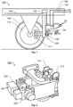
- FIG. 1 we see a schematic illustration of a rail vehicle 100 equipped with a parking brake system according to one embodiment of the invention.
- the parking brake system contains a brake actuator 120 and a brake unit 200.
- the brake actuator 120 is configured to receive a parking-brake command cmd p , which typically has been generated based on a driver's instruction.
- the parking-brake command cmd p may equally well be generated automatically, for example if a particular set of criteria is fulfilled.
- a criterion may be if the power supply to the rail vehicle is interrupted.
- the rail vehicle 100 contains at least one data bus, for example a first data bus 150 configured to communicate control signals CS.
- the parking-brake command cmd p may be received in the brake actuator 120 as one of the control signals CS via the first data bus 150.
- the brake actuator 120 In response to the parking-brake command cmd P the brake actuator 120 is configured to produce an electric brake-force signal BF, which is sent to the brake unit 200.
- the brake unit 200 includes first and second pressing members 211 and 212 respectively and a rotatable member 110, which is mechanically linked to at least one wheel 105 of the rail vehicle 100.
- the brake unit 200 is configured to receive the electric brake-force signal BF, and in response thereto cause the first and second pressing members 211 and 212 to apply a braking force to the rotatable member 110, so as to keep the at least one wheel 105 immobile.
- the parking brake system contains an acceleration sensor 125, and the brake unit 200, in turn, contains a gear assembly 220 and an electric motor 230, for example represented by a stepper motor or a DC motor.
- the gear assembly 220 is arranged to operate mechanically on the first and second pressing members 211 and 212.
- the electric motor 230 is configured to act on the gear assembly 220 so as to cause the first and second pressing members 211 and 212 to move towards or away from the rotatable member 110 and attain a specified position interrelationship.
- an activating parking-brake command cmd P may result in that the parking brake is applied
- a negating parking-brake command cmd P may result in that the parking brake is released.
- the acceleration sensor 125 may be included in the brake actuator 120. However, alternatively, the acceleration sensor 125 may also be arranged at a different location in the rail vehicle 100, such as on a frame/chassis part thereof.
- the acceleration sensor 125 is configured to register movements of the rail vehicle 100 and produce an output signal indicative of a magnitude of the movements of the rail vehicle 100.
- the brake actuator 120 is configured to receive the output signal from the acceleration sensor 125. If the output signal indicates movements of the rail vehicle 100 at a magnitude above a threshold level during a period when the parking-brake command cmd P has instructed the at least one wheel 105 to be immobile, the brake actuator 120 is configured to control the brake actuator 120 to reproduce the electric brake-force signal BF to the electric motor 230 to cause the first and second pressing members 211 and 212 to reapply the braking force to the rotatable member 110, so as to keep the at least one wheel 105 immobile.
- the acceleration sensor 125 registers a movement of the rail vehicle 100 at a magnitude above a threshold level, the brake actuator 120 triggers at least one precautionary measure to be taken.
- the brake actuator 120 is configured to control the brake actuator 120 to reproduce the electric brake-force signal BF to the electric motor 230 to cause the first and second pressing members 211 and 212 to reapply the braking force to the rotatable member 110.
- the brake actuator 120 will reproduce the electric brake-force signal BF to the electric motor 230 to cause the first and second pressing members 211 and 212 to reapply the braking force to the rotatable member 110.
- the brake actuator 120 is configured to generate a first alarm message A1 if the acceleration sensor 125 registers a movement of the rail vehicle 100 at a magnitude above the threshold level during the period when the parking-brake command cmd P has instructed the at least one wheel 105 to be immobile.
- the rail vehicle 100 may contain a second data bus 160, which is configured to communicate status messages SS and to which second data bus 160 the brake actuator 120 is connected.
- the brake actuator 120 may be configured to send the first alarm message A1 as one of the status messages SS over the second data bus 160.
- the brake actuator 120 contains a wireless interface 340 configured to send a second alarm message A2 on a wireless format, such as an SMS (short message service) message in a wireless telecommunication system.
- a wireless format such as an SMS (short message service) message in a wireless telecommunication system.
- the brake actuator 120 may contain an alarm signal generator 350 configured to emit an acoustic signal and/or a visual signal A3.
- the brake actuator 120 is configured to cause the alarm signal generator 350 to emit said signal(s) A3, e.g. an alarm sound and/or a flashing or steady light, if the acceleration sensor 125 registers a movement of the rail vehicle 100 at a magnitude above the threshold level during the period when the parking-brake command cmd P has instructed the at least one wheel 105 to be immobile. Consequently, the acoustic signal A3 may efficiently lead a service technician towards the malfunctioning brake.
- FIG. 2 shows a brake unit 200 according to one embodiment of the invention.
- the brake unit 200 includes first and second pressing members 211 and 212 respectively and a rotatable member 110 that is mechanically linked to at least one wheel 105 of the rail vehicle 100.
- the brake unit 200 is configured to receive the electric brake-force signal BF.
- the brake unit 200 is configured to perform a parking brake operation.
- the parking brake command cmd P typically either means activating the parking brake, i.e. applying the parking brake or deactivating parking brake, i.e. releasing the parking brake.
- the brake command cmd P is configured to cause the at least one wheel 105 to remain immobile.
- a negating parking-brake command cmd P is produced which is configured cause the first and second pressing members 211 and 212 to release an already applied braking force to the rotatable member 110 so as to enable the rotatable member 110 and the at least one wheel 105 to rotate again.
- the gear assembly 220 is arranged to operate mechanically on the first and second pressing members 211 and 212 respectively. Functionally, the gear assembly 220 is located between the electric motor 230 and the pressing members 211 and 212.
- a first specified position interrelationship may correspond to a released state for the parking brake, i.e. wherein the rotatable member 110 and the at least one wheel 105 are enabled to rotate; and a second specified position interrelationship may correspond to a parking-braked state, wherein the first and second pressing members 211 and 212 apply a braking force to the rotatable member 110 so as to keep the at least one wheel 105 immobile.
- the stepper motor is typically a brushless DC electric motor that divides a full rotation into a number of equal steps, say 100, which may be provided by a gear-shaped iron rotor with 25 teeth giving 3,6 degrees of rotation per step.
- the stepper motor 230 can be commanded to move and hold a position at one of these steps by open loop control provided that the motor is adapted to the application in respect to torque and speed.
- the electric motor 230 may instead be Implemented by means of a DC motor. This is beneficial because it is straightforward to control an output torque of the DC motor's power transmission shaft via a control current.
- the parking brake system includes a backup power unit 130, which is configured to accumulate electric power W from a power line 140 in the rail vehicle 100 during normal operation of the rail vehicle 100.
- electric power may be stored in at least one battery and/or at least one capacitive element.
- the backup power unit 130 is configured to automatically provide accumulated electric power stored in the backup power unit 130 to the brake actuator 120 and the brake unit 200.
- the electric motor 130 is enabled to maintain the specified position interrelationship between the first and second pressing members 211 and 212 as given by the electric brake-force signal BF also during the outage of the electric power W.
- the backup power unit 130 is connected between the power line 140 and the brake actuator 120 / brake unit 200.
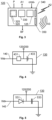
- the backup power unit 130 contains a battery charger 431 and a rechargeable battery 433.
- FIG. 5 shows the backup power unit 130 according to a second embodiment of the invention.
- the backup power unit 130 contains a rectifier 531 and at least one capacitive element 533.
- the backup power unit 130 is connected between the power line 140 and the brake actuator 120 / brake unit 200.
- the brake actuator 120 preferably includes processing circuitry and programmed memory units, the design of which will be briefly described below with reference to Figure 3 .
- FIG. 3 shows a block diagram of the brake actuator 120 according to one embodiment of the invention.
- the brake actuator 120 includes processing circuitry in the form of at least one processor 330 and a memory unit 320, i.e. non-volatile data carrier, storing a computer program 325, which, in turn, contains software for making the at least one processor 330 execute the actions mentioned in this disclosure when the computer program 325 is run on the at least one processor 330.
- the brake actuator 120 may also contain a wireless interface 340 configured to send the second alarm message A2 on a wireless format and/or an alarm signal generator 350 configured to emit acoustic and/or visual signals A3.
- parking brake system is presumed to contain a brake actuator 120 configured to receive a parking-brake command cmd P , and in response thereto produce an electric brake-force signal BF.
- the parking brake system is further presumed to contain a brake unit 200 including first and second pressing members 211 and 212 respectively and a rotatable member 110 that is mechanically linked to at least one wheel 105 of the rail vehicle 100.
- the brake unit 200 is configured to receive the electric brake-force signal BF, and in response thereto cause the first and second pressing members 211 and 212 to apply a braking force to the rotatable member 110 so as to keep the at least one wheel 105 immobile.
- a step 610 it is checked whether an activating parking brake command has been received; and if so, a step 620 follows. Otherwise, the procedure loops back and stays in step 610.
- step 620 the brake actuator 120 controls the brake actuator 120 to produce such an electric brake-force signal BF that the electric motor 230 causes the first and second pressing members 211 and 212 to apply a parking brake force to the rotatable member 110 and thus prevent the at least one wheel 105 from rotating.
- step 630 it is checked if the acceleration sensor 125 has registered a movement of the rail vehicle 100 at a magnitude above a threshold level; and if so, a step 640 follows. Otherwise, a step 650 follows.
- step 640 the brake actuator 120 controls the brake actuator 120 to reproduce the electric brake-force signal BF to the electric motor 230 to cause the first and second pressing members 211 and 212 to reapply the braking force to the rotatable member 110 as described above in order to keep the at least one wheel 105 immobile. Thereafter, the procedure loops back to step 630.
- one or more alarm messages are produced to notify relevant entities/parties.
- step 650 it is checked whether a negating parking brake command has been received; and if so, a step 660 follows. Otherwise, the procedure loops back to step 630.
- step 660 the brake actuator 120 controls the brake actuator 120 to produce such an electric brake-force signal BF that the electric motor 230 causes the first and second pressing members 211 and 212 to release the rotatable member 110 and thus allow the at least one wheel 105 to rotate freely. Thereafter, the procedure loops back to step 610.
- All of the process steps, as well as any sub-sequence of steps, described with reference to Figure 6 may be controlled by means of a programmed processor.
- the embodiments of the invention described above with reference to the drawings comprise processor and processes performed in at least one processor, the invention thus also extends to computer programs, particularly computer programs on or in a carrier, adapted for putting the invention into practice.
- the program may be in the form of source code, object code, a code intermediate source and object code such as in partially compiled form, or in any other form suitable for use in the implementation of the process according to the invention.
- the program may either be a part of an operating system, or be a separate application.
- the carrier may be any entity or device capable of carrying the program.
- the carrier may comprise a storage medium, such as a Flash memory, a ROM (Read Only Memory), for example a DVD (Digital Video/Versatile Disk), a CD (Compact Disc) or a semiconductor ROM, an EPROM (Erasable Programmable Read-Only Memory), an EEPROM (Electrically Erasable Programmable Read-Only Memory), or a magnetic recording medium, for example a floppy disc or hard disc.
- the carrier may be a transmissible carrier such as an electrical or optical signal which may be conveyed via electrical or optical cable or by radio or by other means.
- the carrier When the program is embodied in a signal, which may be conveyed, directly by a cable or other device or means, the carrier may be constituted by such cable or device or means.
- the carrier may be an integrated circuit in which the program is embedded, the integrated circuit being adapted for performing, or for use in the performance of, the relevant processes.
Landscapes
- Engineering & Computer Science (AREA)
- Mechanical Engineering (AREA)
- Transportation (AREA)
- General Engineering & Computer Science (AREA)
- Manufacturing & Machinery (AREA)
- Chemical & Material Sciences (AREA)
- Chemical Kinetics & Catalysis (AREA)
- Electrochemistry (AREA)
- General Chemical & Material Sciences (AREA)
- Automation & Control Theory (AREA)
- Regulating Braking Force (AREA)
- Valves And Accessory Devices For Braking Systems (AREA)
Claims (14)
- Feststellbremsanlage für ein Schienenfahrzeug (100), wobei die Feststellbremsanlage aufweist:einen Bremsaktuator (120), der konfiguriert ist, um einen Feststellbremsbefehl (cmdp) zu empfangen und ansprechend darauf ein elektrisches Bremskraftsignal (BF) zu erzeugen,eine Bremseinheit (200), die aufweist: erste und zweite Druckelemente (211, 212), ein drehbares Element (110), das mit wenigstens einem Rad (105) des Schienenfahrzeugs (100) mechanisch verbunden ist, wobei die Bremseinheit (200) konfiguriert ist, um das elektrische Bremskraftsignal (BF) zu empfangen und ansprechend darauf zu bewirken, dass die ersten und zweiten Druckelemente (211, 212) eine Bremskraft auf das drehbare Element (110) anwenden, um das wenigstens eine Rad (105) unbeweglich zu halten, eine Getriebeanordnung (220), die eingerichtet ist, um mechanisch auf die ersten und zweiten Druckelemente (211; 212) zu wirken, und einen Elektromotor (230), der konfiguriert ist, um ansprechend auf das elektrische Bremskraftsignal (BF) auf die Getriebeanordnung (220) einzuwirken, um zu bewirken, dass die ersten und zweiten Druckelemente (211; 212) sich auf das drehbare Element (110) zu oder davon weg bewegen und eine spezifizierte Positionsbeziehung erreichen,dadurch gekennzeichnet, dass:
die Feststellbremsanlage ferner aufweist:einen Beschleunigungssensor (125), der konfiguriert ist, um Bewegungen des Schienenfahrzeugs (100) zu registrieren und ein Ausgangssignal, das einen Betrag der Bewegungen des Schienenfahrzeugs (100) anzeigt, zu erzeugen, und wobei der Bremsaktuator (120) konfiguriert ist, um:das Ausgangssignal zu empfangen; und falls das Ausgangssignal während einer Zeitspanne, zu welcher der Feststellbremsbefehl (cmdP) das wenigstens eine Rad (105) angewiesen hat, unbeweglich zu sein, Bewegungen des Schienenfahrzeugs (100) mit einem Betrag über dem Schwellpegel anzeigt,den Bremsaktuator (120) derart zu steuern, dass er das elektrische Bremskraftsignal (BF) an den Elektromotor (230) wieder erzeugt, um zu bewirken, dass die ersten und zweiten Druckelemente (211, 212) die Bremskraft erneut auf das drehbare Element (110) anwenden, um das wenigstens eine Rad (105) unbeweglich zu halten, undwobei das Feststellbremssystem ferner aufweist:
eine Notstromversorgungseinheit (130), die konfiguriert ist, um während des Betriebs des Schienenfahrzeugs (100) elektrische Leistung (W) von einer Stromleitung (140) in dem Schienenfahrzeug (100) anzusammeln, und die angesammelte elektrische Leistung im Fall eines Ausfalls der elektrischen Leistung (W) an den Bremsaktuator (130) und die Bremseinheit (200) bereitzustellen, um auf diese Weise zu ermöglichen, dass der Elektromotor (130) die sich aus dem elektrischen Bremskraftsignal (BF) ergebende spezifizierte Positionsbeziehung zwischen den ersten und zweiten Druckelementen (211; 212) auch während dieses Ausfalls aufrecht erhält. - Feststellbremsanlage nach Anspruch 1, wobei der Bremsaktuator (120) ferner konfiguriert ist, um eine erste Alarmnachricht (A1) zu erzeugen, falls der Beschleunigungssensor (125) während der Zeitspanne, zu welcher der Feststellbremsbefehl (cmdP) das wenigstens eine Rad (105) angewiesen hat, unbeweglich zu sein, eine Bewegung des Schienenfahrzeugs (100) mit einem Betrag oberhalb eines Schwellpegels registriert.
- Feststellbremsanlage nach Anspruch 2, wobei der Bremsaktuator (120) mit wenigstens einem Datenbus (150, 160) in dem Schienenfahrzeug (100) verbunden ist, wobei der wenigstens eine Datenbus (150, 160) konfiguriert ist, um Steuersignale (CS) und/oder Statusnachrichten (SS) zu übertragen.
- Feststellbremsanlage nach Anspruch 3, wobei der Bremsaktuator (120) konfiguriert ist, um die erste Alarmnachricht (A1) als eine der Statusnachrichten (SS) über einen des wenigstens einen Datenbusses (160) zu senden.
- Feststellbremsanlage nach einem der vorhergehenden Ansprüche, wobei der Bremsaktuator (120) ferner eine drahtlose Schnittstelle (340) aufweist, die konfiguriert ist, um eine zweite Alarmnachricht (A2) auf einem drahtlosen Format zu senden, falls der Beschleunigungssensor (125) während der Zeitspanne, zu welcher der Feststellbremsbefehl (cmdP) das wenigstens eine Rad (105) angewiesen hat, unbeweglich zu sein, eine Bewegung des Schienenfahrzeugs (100) mit einem Betrag oberhalb des Schwellpegels registriert.
- Feststellbremsanlage nach einem der vorhergehenden Ansprüche, wobei der Bremsaktuator (120) ferner einen Alarmsignalgenerator (350) aufweist, der konfiguriert ist, um ein akustisches Signal und/oder ein visuelles Signal (A3) auszusenden, falls der Beschleunigungssensor (125) während der Zeitspanne, zu welcher der Feststellbremsbefehl (cmdP) das wenigstens eine Rad (105) angewiesen hat, unbeweglich zu sein, eine Bewegung des Schienenfahrzeugs (100) mit einem Betrag oberhalb eines Schwellpegels registriert.
- Feststellbremsanlage nach Anspruch 1, wobei die Notstromversorgungseinheit (130) aufweist:wenigstens eine wiederaufladbare Batterie (433), undein Batterieladegerät (431), das mit der Stromleitung (140) verbunden ist und konfiguriert ist, um von der Stromleitung (140) empfangene elektrische Leistung (W) an die wenigstens eine wiederaufladbare Batterie (433) zu überführen, wobei die wenigstens eine wiederaufladbare Batterie (433) eingerichtet ist, um elektrische Leistung an den Bremsaktuator (120) und die Bremseinheit (200) zuzuführen, falls die elektrische Leistung (W) auf der Stromleistung ausfällt.
- Feststellbremsanlage nach einem der Ansprüche 1 oder 7, wobei die Notstromversorgungseinheit (130) aufweist:wenigstens ein kapazitives Element (533), undeinen Gleichrichter (531), der mit der Stromleitung (140) verbunden ist und konfiguriert ist, um von der Stromleitung (140) empfangene elektrische Leistung (W) an das wenigstens eine kapazitive Element (533) zu überführen,wobei das wenigstens eine kapazitive Element (533) eingerichtet ist, um elektrische Leistung an den Bremsaktuator (120) und die Bremseinheit (200) zuzuführen, falls die elektrische Leistung (W) auf der Stromleitung (140) ausfällt.
- Computerimplementiertes Verfahren zur Steuerung einer Feststellbremsanlage eines Schienenfahrzeugs (100), wobei die Feststellbremsanlage aufweist: einen Bremsaktuator (120), der konfiguriert ist, um einen Feststellbremsbefehl (cmdP) zu empfangen und ansprechend darauf ein elektrisches Bremskraftsignal (BF) zu erzeugen, und eine Bremseinheit (200), die aufweist: erste und zweite Druckelemente (211, 212), ein drehbares Element (110), das mit wenigstens einem Rad (105) des Schienenfahrzeugs (100) mechanisch verbunden ist, wobei die Bremseinheit (200) konfiguriert ist, um das elektrische Bremskraftsignal (BF) zu empfangen und ansprechend darauf zu bewirken, dass die ersten und zweiten Druckelemente (211, 212) eine Bremskraft auf das drehbare Element (110) anwenden, um das wenigstens eine Rad (105) unbeweglich zu halten, wobei die Bremseinheit (200) ferner eine Getriebeanordnung (220), die eingerichtet ist, um mechanisch auf die ersten und zweiten Druckelemente (211; 212) zu wirken, und einen Elektromotor (230), der konfiguriert ist, um ansprechend auf das elektrische Bremskraftsignal (BF) auf die Getriebeanordnung (220) einzuwirken, um zu bewirken, dass die ersten und zweiten Druckelemente (211; 212) sich auf das drehbare Element (110) zu oder davon weg bewegen und eine spezifizierte Positionsbeziehung erreichen,
gekennzeichnet durch:Registrieren von Bewegungen des Schienenfahrzeugs (100),Erzeugen eines Ausgangssignals, das einen Betrag der Bewegungen des Schienenfahrzeugs (100) anzeigt,Empfangen des Ausgangssignals; und falls das Ausgangssignal während einer Zeitspanne, zu welcher der Feststellbremsbefehl (cmdP) das wenigstens eine Rad (105) angewiesen hat, unbeweglich zu sein, Bewegungen des Schienenfahrzeugs (100) mit einem Betrag über dem Schwellpegel anzeigt,Steuern des Bremsaktuators derart, dass er das elektrische Bremskraftsignal (BF) an den Elektromotor (230) wieder erzeugt, um zu bewirken, dass die ersten und zweiten Druckelemente (211, 212) die Bremskraft erneut auf das drehbare Element (110) anwenden, um das wenigstens eine Rad (105) unbeweglich zu halten,Ansammeln von elektrischer Leistung (W) von einer Stromleitung (140) in einer Notstromversorgungseinheit in dem Schienenfahrzeug (100) während des Betriebs des Schienenfahrzeugs (100), undim Fall eines Ausfalls der elektrischen Leistung (W), Bereitstellen der angesammelten elektrischen Leistung an den Bremsaktuator (130) und die Bremseinheit (200), um auf diese Weise zu ermöglichen, dass der Elektromotor (130) die sich aus dem elektrischen Bremskraftsignal (BF) ergebende spezifizierte Positionsbeziehung zwischen den ersten und zweiten Druckelementen (211; 212) auch während dieses Ausfalls aufrechterhält. - Verfahren nach Anspruch 9, das ferner aufweist:
Erzeugen einer ersten Alarmnachricht (A1), falls der Beschleunigungssensor (125) während der Zeitspanne, zu welcher der Feststellbremsbefehl (cmdp) das wenigstens eine Rad (105) angewiesen hat, unbeweglich zu sein, eine Bewegung des Schienenfahrzeugs (100) mit einem Betrag oberhalb eines Schwellpegels registriert. - Verfahren nach einem der Ansprüche 9 oder 10, das ferner aufweist:
Erzeugen einer zweiten Alarmnachricht (A2) auf einem drahtlosen Format, falls der Beschleunigungssensor (125) während der Zeitspanne, zu welcher der Feststellbremsbefehl (cmdP) das wenigstens eine Rad (105) angewiesen hat, unbeweglich zu sein, eine Bewegung des Schienenfahrzeugs (100) mit einem Betrag oberhalb des Schwellpegels registriert. - Verfahren nach einem der Ansprüche 9 bis 11, das ferner aufweist:
Aussenden eines akustischen Signals und/oder eines visuellen Signals (A3), falls der Beschleunigungssensor (125) während der Zeitspanne, zu welcher der Feststellbremsbefehl (cmdP) das wenigstens eine Rad (105) angewiesen hat, unbeweglich zu sein, eine Bewegung des Schienenfahrzeugs (100) mit einem Betrag oberhalb eines Schwellpegels registriert. - Computerprogramm (325), das in einen nichtflüchtigen Datenträger (320) ladbar ist, der mit wenigstens einem Prozessor (330) kommunikationsfähig verbunden ist, wobei das Computerprogramm (325) Software zur Ausführung des Verfahrens nach einem der Ansprüche 9 bis 12 aufweist, wenn das Computerprogramm (325) auf dem wenigstens einen Prozessor (330) abläuft.
- Nichtflüchtiger Datenträger (320), der das Computerprogramm (325) nach Anspruch 13 enthält.
Priority Applications (5)
| Application Number | Priority Date | Filing Date | Title |
|---|---|---|---|
| ES22157538T ES3031695T3 (en) | 2022-02-18 | 2022-02-18 | Parking brake system, computer-implemented method of controlling a parking brake system of a rail vehicle, computer program and non-volatile data carrier |
| EP22157538.4A EP4230486B1 (de) | 2022-02-18 | 2022-02-18 | Feststellbremsanlage, computerimplementiertes verfahren zur steuerung einer feststellbremsanlage eines schienenfahrzeugs, computerprogramm und nichtflüchtiger datenträger |
| US18/834,031 US20250100518A1 (en) | 2022-02-18 | 2022-11-24 | Parking brake system, computer-implemented method of controlling a parking brake system of a rail vehicle, computer program and non-volatile data carrier |
| PCT/EP2022/083172 WO2023156035A1 (en) | 2022-02-18 | 2022-11-24 | Parking brake system, computer-implemented method of controlling a parking brake system of a rail vehicle, computer program and non-volatile data carrier |
| CN202280090907.4A CN118695973A (zh) | 2022-02-18 | 2022-11-24 | 驻车制动系统、控制轨道车辆的驻车制动系统的计算机实现的方法、计算机程序和非易失性数据载体 |
Applications Claiming Priority (1)
| Application Number | Priority Date | Filing Date | Title |
|---|---|---|---|
| EP22157538.4A EP4230486B1 (de) | 2022-02-18 | 2022-02-18 | Feststellbremsanlage, computerimplementiertes verfahren zur steuerung einer feststellbremsanlage eines schienenfahrzeugs, computerprogramm und nichtflüchtiger datenträger |
Publications (3)
| Publication Number | Publication Date |
|---|---|
| EP4230486A1 EP4230486A1 (de) | 2023-08-23 |
| EP4230486C0 EP4230486C0 (de) | 2025-06-04 |
| EP4230486B1 true EP4230486B1 (de) | 2025-06-04 |
Family
ID=80628832
Family Applications (1)
| Application Number | Title | Priority Date | Filing Date |
|---|---|---|---|
| EP22157538.4A Active EP4230486B1 (de) | 2022-02-18 | 2022-02-18 | Feststellbremsanlage, computerimplementiertes verfahren zur steuerung einer feststellbremsanlage eines schienenfahrzeugs, computerprogramm und nichtflüchtiger datenträger |
Country Status (5)
| Country | Link |
|---|---|
| US (1) | US20250100518A1 (de) |
| EP (1) | EP4230486B1 (de) |
| CN (1) | CN118695973A (de) |
| ES (1) | ES3031695T3 (de) |
| WO (1) | WO2023156035A1 (de) |
Family Cites Families (10)
| Publication number | Priority date | Publication date | Assignee | Title |
|---|---|---|---|---|
| CN101065281A (zh) * | 2004-11-29 | 2007-10-31 | 西门子公司 | 电动机械的制动装置 |
| DE102008007940B4 (de) * | 2008-02-07 | 2011-04-07 | Knorr-Bremse Systeme für Nutzfahrzeuge GmbH | Sicherheitsvorrichtung für eine elektrisch gesteuerte Feststellbremse und Verfahren zum Betreiben einer Sicherheitsvorrichtung für eine elektrisch gesteuerte Feststellbremse |
| AT511269B1 (de) * | 2011-03-22 | 2013-01-15 | Oebb Tech Services Gmbh | Automatische bremsüberwachung |
| US20140060979A1 (en) * | 2012-09-06 | 2014-03-06 | Amsted Rail Company, Inc. | Railcar handbrake monitor |
| JP6091841B2 (ja) * | 2012-10-25 | 2017-03-08 | Ntn株式会社 | パーキング機能付き電動ブレーキアクチュエータ |
| CA2929654A1 (en) * | 2013-11-14 | 2015-05-21 | Wabtec Holding Corp. | Hand brake determination method and system for an air brake system and improved hand brake arrangement |
| DE102014006314A1 (de) | 2014-04-30 | 2015-11-05 | Man Truck & Bus Ag | Elektrische Feststellbremse |
| JP2020533933A (ja) | 2017-09-06 | 2020-11-19 | 北京天佑新轡高新技術有限公司Beijing Tianyouxinpei high−tech Co.,Ltd. | マイクロコンピュータ制御の電気機械制動システム |
| ES2997158T3 (en) * | 2018-10-03 | 2025-02-14 | Schweizerische Bundesbahnen Sbb | Brake system for a rail vehicle |
| CN111422174B (zh) | 2020-06-09 | 2020-08-28 | 上海全路通铁道装备有限公司 | 一种铁路客车自动驻车制动装置及其制动方法 |
-
2022
- 2022-02-18 ES ES22157538T patent/ES3031695T3/es active Active
- 2022-02-18 EP EP22157538.4A patent/EP4230486B1/de active Active
- 2022-11-24 US US18/834,031 patent/US20250100518A1/en active Pending
- 2022-11-24 CN CN202280090907.4A patent/CN118695973A/zh active Pending
- 2022-11-24 WO PCT/EP2022/083172 patent/WO2023156035A1/en not_active Ceased
Also Published As
| Publication number | Publication date |
|---|---|
| CN118695973A (zh) | 2024-09-24 |
| EP4230486A1 (de) | 2023-08-23 |
| WO2023156035A1 (en) | 2023-08-24 |
| EP4230486C0 (de) | 2025-06-04 |
| ES3031695T3 (en) | 2025-07-10 |
| US20250100518A1 (en) | 2025-03-27 |
Similar Documents
| Publication | Publication Date | Title |
|---|---|---|
| US10259439B2 (en) | Electric parking brake control and method | |
| US9605722B2 (en) | Electric brake actuator with parking function | |
| US6203116B1 (en) | Method for operating an electromechanical brake system | |
| CN111483447B (zh) | 用于将控制器激活并且去除激活的方法 | |
| US20060152080A1 (en) | Protection method in a vehicle brake system having electric brakes | |
| CN106240547A (zh) | 用于制动车辆的方法 | |
| JP2000297834A (ja) | ブレーキ移動クリアランス制御用電動モータを有する車両用ブレーキ装置 | |
| CN112937309B (zh) | 用于控制机动车的制动操作的方法 | |
| CN102407842B (zh) | 具有在控制仪停止运行后自动再校准功能的驻车制动器 | |
| CN109715456B (zh) | 用于车辆的制动系统-控制器 | |
| GB2472392A (en) | Regenerative braking system having an electric drive means to actuate a mechanical braking device | |
| EP4230486B1 (de) | Feststellbremsanlage, computerimplementiertes verfahren zur steuerung einer feststellbremsanlage eines schienenfahrzeugs, computerprogramm und nichtflüchtiger datenträger | |
| CN116749936A (zh) | 一种车辆的制动系统及车辆 | |
| EP4223612B1 (de) | Bremssystem für ein schienenfahrzeug | |
| CN113619548A (zh) | 用于运行驻车制动系统的方法和装置 | |
| CN118977690A (zh) | 一种冗余制动的电子机械制动系统及车辆 | |
| EP4360972A1 (de) | Bremseinheit für ein schienenfahrzeug | |
| KR20230006260A (ko) | 전자식 주차 브레이크 시스템 및 그 제어방법 | |
| EP4245620B1 (de) | Bremssystem, computerimplementiertes verfahren zur steuerung eines bremssystems eines schienenfahrzeugs, computerprogramm und nichtflüchtiger datenträger | |
| JP7793112B2 (ja) | ブレーキ制御装置、機械ブレーキ装置、およびブレーキ制御システム | |
| JP7785245B2 (ja) | ブレーキ制御装置、機械ブレーキ装置、およびブレーキ制御システム | |
| EP4663490A1 (de) | Bremssystem für ein schienenfahrzeug, computerimplementiertes verfahren, computerprogramm und nichtflüchtiger datenträger | |
| JP7837484B2 (ja) | 推定装置、ブレーキ制御装置、および推定方法 | |
| US20260109331A1 (en) | System and method for controlling parking brake using back electromotive force | |
| KR20250143120A (ko) | 철도 차량에서 적어도 부분적으로 전기적으로 작동되는 마찰 브레이크 컨트롤러를 작동하기 위한 조합된 에너지 저장 장치 유형을 포함하는 에너지 공급 시스템을 구비한 브레이크 시스템 |
Legal Events
| Date | Code | Title | Description |
|---|---|---|---|
| PUAI | Public reference made under article 153(3) epc to a published international application that has entered the european phase |
Free format text: ORIGINAL CODE: 0009012 |
|
| STAA | Information on the status of an ep patent application or granted ep patent |
Free format text: STATUS: THE APPLICATION HAS BEEN PUBLISHED |
|
| AK | Designated contracting states |
Kind code of ref document: A1 Designated state(s): AL AT BE BG CH CY CZ DE DK EE ES FI FR GB GR HR HU IE IS IT LI LT LU LV MC MK MT NL NO PL PT RO RS SE SI SK SM TR |
|
| STAA | Information on the status of an ep patent application or granted ep patent |
Free format text: STATUS: REQUEST FOR EXAMINATION WAS MADE |
|
| 17P | Request for examination filed |
Effective date: 20231201 |
|
| RBV | Designated contracting states (corrected) |
Designated state(s): AL AT BE BG CH CY CZ DE DK EE ES FI FR GB GR HR HU IE IS IT LI LT LU LV MC MK MT NL NO PL PT RO RS SE SI SK SM TR |
|
| GRAP | Despatch of communication of intention to grant a patent |
Free format text: ORIGINAL CODE: EPIDOSNIGR1 |
|
| STAA | Information on the status of an ep patent application or granted ep patent |
Free format text: STATUS: GRANT OF PATENT IS INTENDED |
|
| GRAS | Grant fee paid |
Free format text: ORIGINAL CODE: EPIDOSNIGR3 |
|
| GRAA | (expected) grant |
Free format text: ORIGINAL CODE: 0009210 |
|
| STAA | Information on the status of an ep patent application or granted ep patent |
Free format text: STATUS: THE PATENT HAS BEEN GRANTED |
|
| INTG | Intention to grant announced |
Effective date: 20250403 |
|
| AK | Designated contracting states |
Kind code of ref document: B1 Designated state(s): AL AT BE BG CH CY CZ DE DK EE ES FI FR GB GR HR HU IE IS IT LI LT LU LV MC MK MT NL NO PL PT RO RS SE SI SK SM TR |
|
| REG | Reference to a national code |
Ref country code: GB Ref legal event code: FG4D |
|
| REG | Reference to a national code |
Ref country code: CH Ref legal event code: EP |
|
| REG | Reference to a national code |
Ref country code: IE Ref legal event code: FG4D |
|
| U01 | Request for unitary effect filed |
Effective date: 20250604 |
|
| U07 | Unitary effect registered |
Designated state(s): AT BE BG DE DK EE FI FR IT LT LU LV MT NL PT RO SE SI Effective date: 20250611 |
|
| REG | Reference to a national code |
Ref country code: ES Ref legal event code: FG2A Ref document number: 3031695 Country of ref document: ES Kind code of ref document: T3 Effective date: 20250710 |
|
| PG25 | Lapsed in a contracting state [announced via postgrant information from national office to epo] |
Ref country code: NO Free format text: LAPSE BECAUSE OF FAILURE TO SUBMIT A TRANSLATION OF THE DESCRIPTION OR TO PAY THE FEE WITHIN THE PRESCRIBED TIME-LIMIT Effective date: 20250904 Ref country code: GR Free format text: LAPSE BECAUSE OF FAILURE TO SUBMIT A TRANSLATION OF THE DESCRIPTION OR TO PAY THE FEE WITHIN THE PRESCRIBED TIME-LIMIT Effective date: 20250905 |
|
| PG25 | Lapsed in a contracting state [announced via postgrant information from national office to epo] |
Ref country code: PL Free format text: LAPSE BECAUSE OF FAILURE TO SUBMIT A TRANSLATION OF THE DESCRIPTION OR TO PAY THE FEE WITHIN THE PRESCRIBED TIME-LIMIT Effective date: 20250604 |
|
| PG25 | Lapsed in a contracting state [announced via postgrant information from national office to epo] |
Ref country code: HR Free format text: LAPSE BECAUSE OF FAILURE TO SUBMIT A TRANSLATION OF THE DESCRIPTION OR TO PAY THE FEE WITHIN THE PRESCRIBED TIME-LIMIT Effective date: 20250604 |
|
| PG25 | Lapsed in a contracting state [announced via postgrant information from national office to epo] |
Ref country code: RS Free format text: LAPSE BECAUSE OF FAILURE TO SUBMIT A TRANSLATION OF THE DESCRIPTION OR TO PAY THE FEE WITHIN THE PRESCRIBED TIME-LIMIT Effective date: 20250904 |
|
| PG25 | Lapsed in a contracting state [announced via postgrant information from national office to epo] |
Ref country code: IS Free format text: LAPSE BECAUSE OF FAILURE TO SUBMIT A TRANSLATION OF THE DESCRIPTION OR TO PAY THE FEE WITHIN THE PRESCRIBED TIME-LIMIT Effective date: 20251004 |
|
| PG25 | Lapsed in a contracting state [announced via postgrant information from national office to epo] |
Ref country code: SM Free format text: LAPSE BECAUSE OF FAILURE TO SUBMIT A TRANSLATION OF THE DESCRIPTION OR TO PAY THE FEE WITHIN THE PRESCRIBED TIME-LIMIT Effective date: 20250604 |
|
| PG25 | Lapsed in a contracting state [announced via postgrant information from national office to epo] |
Ref country code: CZ Free format text: LAPSE BECAUSE OF FAILURE TO SUBMIT A TRANSLATION OF THE DESCRIPTION OR TO PAY THE FEE WITHIN THE PRESCRIBED TIME-LIMIT Effective date: 20250604 |
|
| PG25 | Lapsed in a contracting state [announced via postgrant information from national office to epo] |
Ref country code: SK Free format text: LAPSE BECAUSE OF FAILURE TO SUBMIT A TRANSLATION OF THE DESCRIPTION OR TO PAY THE FEE WITHIN THE PRESCRIBED TIME-LIMIT Effective date: 20250604 |
|
| PLBE | No opposition filed within time limit |
Free format text: ORIGINAL CODE: 0009261 |
|
| STAA | Information on the status of an ep patent application or granted ep patent |
Free format text: STATUS: NO OPPOSITION FILED WITHIN TIME LIMIT |
|
| REG | Reference to a national code |
Ref country code: CH Ref legal event code: L10 Free format text: ST27 STATUS EVENT CODE: U-0-0-L10-L00 (AS PROVIDED BY THE NATIONAL OFFICE) Effective date: 20260416 |