EP4245620B1 - Bremssystem, computerimplementiertes verfahren zur steuerung eines bremssystems eines schienenfahrzeugs, computerprogramm und nichtflüchtiger datenträger - Google Patents
Bremssystem, computerimplementiertes verfahren zur steuerung eines bremssystems eines schienenfahrzeugs, computerprogramm und nichtflüchtiger datenträger Download PDFInfo
- Publication number
- EP4245620B1 EP4245620B1 EP22162522.1A EP22162522A EP4245620B1 EP 4245620 B1 EP4245620 B1 EP 4245620B1 EP 22162522 A EP22162522 A EP 22162522A EP 4245620 B1 EP4245620 B1 EP 4245620B1
- Authority
- EP
- European Patent Office
- Prior art keywords
- brake
- braking system
- pressing members
- deicing
- rotatable member
- Prior art date
- Legal status (The legal status is an assumption and is not a legal conclusion. Google has not performed a legal analysis and makes no representation as to the accuracy of the status listed.)
- Active
Links
Images

Classifications
-
- B—PERFORMING OPERATIONS; TRANSPORTING
- B60—VEHICLES IN GENERAL
- B60T—VEHICLE BRAKE CONTROL SYSTEMS OR PARTS THEREOF; BRAKE CONTROL SYSTEMS OR PARTS THEREOF, IN GENERAL; ARRANGEMENT OF BRAKING ELEMENTS ON VEHICLES IN GENERAL; PORTABLE DEVICES FOR PREVENTING UNWANTED MOVEMENT OF VEHICLES; VEHICLE MODIFICATIONS TO FACILITATE COOLING OF BRAKES
- B60T13/00—Transmitting braking action from initiating means to ultimate brake actuator with power assistance or drive; Brake systems incorporating such transmitting means, e.g. air-pressure brake systems
- B60T13/74—Transmitting braking action from initiating means to ultimate brake actuator with power assistance or drive; Brake systems incorporating such transmitting means, e.g. air-pressure brake systems with electrical assistance or drive
- B60T13/741—Transmitting braking action from initiating means to ultimate brake actuator with power assistance or drive; Brake systems incorporating such transmitting means, e.g. air-pressure brake systems with electrical assistance or drive acting on an ultimate actuator
-
- B—PERFORMING OPERATIONS; TRANSPORTING
- B60—VEHICLES IN GENERAL
- B60T—VEHICLE BRAKE CONTROL SYSTEMS OR PARTS THEREOF; BRAKE CONTROL SYSTEMS OR PARTS THEREOF, IN GENERAL; ARRANGEMENT OF BRAKING ELEMENTS ON VEHICLES IN GENERAL; PORTABLE DEVICES FOR PREVENTING UNWANTED MOVEMENT OF VEHICLES; VEHICLE MODIFICATIONS TO FACILITATE COOLING OF BRAKES
- B60T13/00—Transmitting braking action from initiating means to ultimate brake actuator with power assistance or drive; Brake systems incorporating such transmitting means, e.g. air-pressure brake systems
- B60T13/74—Transmitting braking action from initiating means to ultimate brake actuator with power assistance or drive; Brake systems incorporating such transmitting means, e.g. air-pressure brake systems with electrical assistance or drive
-
- B—PERFORMING OPERATIONS; TRANSPORTING
- B60—VEHICLES IN GENERAL
- B60T—VEHICLE BRAKE CONTROL SYSTEMS OR PARTS THEREOF; BRAKE CONTROL SYSTEMS OR PARTS THEREOF, IN GENERAL; ARRANGEMENT OF BRAKING ELEMENTS ON VEHICLES IN GENERAL; PORTABLE DEVICES FOR PREVENTING UNWANTED MOVEMENT OF VEHICLES; VEHICLE MODIFICATIONS TO FACILITATE COOLING OF BRAKES
- B60T17/00—Component parts, details, or accessories of power brake systems not covered by groups B60T8/00, B60T13/00 or B60T15/00, or presenting other characteristic features
- B60T17/002—Air treatment devices
- B60T17/006—Anti-frost devices
-
- B—PERFORMING OPERATIONS; TRANSPORTING
- B60—VEHICLES IN GENERAL
- B60T—VEHICLE BRAKE CONTROL SYSTEMS OR PARTS THEREOF; BRAKE CONTROL SYSTEMS OR PARTS THEREOF, IN GENERAL; ARRANGEMENT OF BRAKING ELEMENTS ON VEHICLES IN GENERAL; PORTABLE DEVICES FOR PREVENTING UNWANTED MOVEMENT OF VEHICLES; VEHICLE MODIFICATIONS TO FACILITATE COOLING OF BRAKES
- B60T17/00—Component parts, details, or accessories of power brake systems not covered by groups B60T8/00, B60T13/00 or B60T15/00, or presenting other characteristic features
- B60T17/18—Safety devices; Monitoring
- B60T17/22—Devices for monitoring or checking brake systems; Signal devices
- B60T17/221—Procedure or apparatus for checking or keeping in a correct functioning condition of brake systems
-
- B—PERFORMING OPERATIONS; TRANSPORTING
- B60—VEHICLES IN GENERAL
- B60T—VEHICLE BRAKE CONTROL SYSTEMS OR PARTS THEREOF; BRAKE CONTROL SYSTEMS OR PARTS THEREOF, IN GENERAL; ARRANGEMENT OF BRAKING ELEMENTS ON VEHICLES IN GENERAL; PORTABLE DEVICES FOR PREVENTING UNWANTED MOVEMENT OF VEHICLES; VEHICLE MODIFICATIONS TO FACILITATE COOLING OF BRAKES
- B60T8/00—Arrangements for adjusting wheel-braking force to meet varying vehicular or ground-surface conditions, e.g. limiting or varying distribution of braking force
- B60T8/17—Using electrical or electronic regulation means to control braking
- B60T8/1701—Braking or traction control means specially adapted for particular types of vehicles
- B60T8/1705—Braking or traction control means specially adapted for particular types of vehicles for rail vehicles
Definitions
- the present invention relates generally to retardation and immobilization of rail vehicles. Especially, the invention relates to a braking system for a rail vehicle according to the preamble of claim 1 and a corresponding computer-implemented method. The invention also relates to a computer program and a non-volatile data carrier storing such a computer program.
- the onboard motors are typically engaged as generators to decelerate the rail vehicle.
- a dedicated brake function will always be needed to ensure emergency braking functionality and that the rail vehicle remains stationary after that it has been brought to a stop.
- the same brake units are used for different types of braking functionality, such as service braking, emergency braking and parking braking.
- Today's rail vehicle brakes characteristically use pneumatically regulated brakes. This is disadvantageous inter alia due to their slow and imprecise regulation, however also because the risk of leakages and resulting malfunction.
- US 2020/0198605 describes a microcomputer-controlled electromechanical braking system containing an electromechanical braking control device and an electromechanical braking unit.
- the electromechanical braking control device includes a braking microcomputer control unit, an electromechanical control unit and a standby power supply module.
- the braking microcomputer control unit receives a braking instruction signal sent by a driver or an automatic driving system, performs the calculation of a target braking force and braking management. If the electromagnetic brake is powered off, a screw-and-nut arrangement locks the brake to maintain the braking force. When a torque motor rotor rotates reversely, the nut makes a translational motion reversely, and the braking force is released.
- US 4 809 824 A discloses a braking system for a rail vehicle comprising a brake actuator configured to receive a brake command, and in response thereto produce an electric brake-force signal commanding a brake action, and a brake unit comprising first and second pressing members and a rotatable member being mechanically linked to at least one wheel of the rail vehicle.
- the brake unit is configured to receive the electric brake-force signal, and in response thereto cause the first and second pressing members to execute the brake action with respect to the rotatable member, the brake unit further comprises a gear assembly arranged to operate mechanically on the first and second pressing members and an electric motor configured to, in response to the electric brake-force signal, act on the gear assembly so as to cause the first and second pressing members to move towards or away from the rotatable member.
- JP H0671947 shows a defroster device and a running braking device for a vehicle, in which one of the wheels does not slip or the brakes do not have any effect when braking is performed.
- a transmission is equipped with a defroster device, wherein a brake fork is pivotally supported on a brake operation shaft of a braking device.
- the brake fork is configured to engage with a defroster slider for actuating the defroster device.
- a cam mechanism allows the brake fork to slide in the defroster direction during braking when the brake operation shaft is rotated.
- JP 4719700 discloses an electric parking brake apparatus that operates wheel brakes by driving a brake operating force transmission system in one direction by a brake operating force generated by an electric motor, and to hold the brake operating force by an electromagnetic brake when the electric motor is stopped.
- the presence or absence of freezing of the brake operating force transmission system is determined depending on whether or not it is difficult to move the brake operating force transmission system. If a freezing occurs, ice adhered to the brake operating force transmission system may be crushed by driving the electric motor in one direction to further pull the brake operating force transmission system.
- electromechanical braking systems as such, are known.
- the prior art also includes a solution for detecting and removing ice in an electric parking brake apparatus for a vehicle.
- the object of the present invention is therefore to offer a solution that solves the above problem and provides an electric-based braking function for a rail vehicle, which is unaffected by the weather conditions.
- a braking system for a rail vehicle which braking system contains a brake actuator and a brake unit.
- the brake unit includes first and second pressing members and a rotatable member being mechanically linked to at least one wheel of the rail vehicle.
- the brake unit also contains a gear assembly arranged to operate mechanically on the first and second pressing members and an electric motor.
- the brake actuator is configured to receive a brake command, and in response thereto produce an electric brake-force signal commanding a brake action.
- the brake unit is configured to receive the electric brake-force signal, and in response thereto control the electric motor to act on the gear assembly so that the first and second pressing members are caused to move towards or away from the rotatable member.
- the brake actuator is configured to produce the electric brake-force signal in such a way that the brake action involves moving the first and second pressing members away from the rotatable member.
- the above braking system is advantageous because the active outward movement of the first and second pressing members has a highly efficient ice-breaking effect on any ice formation that may have occurred on the braking system at any point in time, i.e. during travel as well as while the train vehicle has stopped at a station.
- the brake actuator is configured to produce the electric brake-force signal in such a way that the brake action involves moving the first and second pressing members towards and away from the rotatable member in a vibrating movement pattern.
- These alternatingly outward and inward movements of the pressing members has an ice-crushing effect that removes any ice from the braking system in a very efficient manner.
- this vibration may be employed with purpose of deicing irrespective of how the first and second pressing members are arranged initially, e.g. in contact with the rotatable member or in an unbraked state.
- a temperature sensor is arranged to generate a temperature signal indicative of an ambient temperature level.
- the temperature signal may be obtained from an onboard sensor for providing general temperature information to various units and functionalities in the train vehicle.
- a dedicated temperature sensor may be integrated into the brake actuator.
- the brake actuator is configured to receive the temperature signal. If the ambient temperature level is less than a threshold temperature during at least a predefined period, the brake actuator is configured to produce a first trigger signal that causes the deicing criterion to be fulfilled. This means that if for example the rail vehicle is exposed to freezing degrees, a deicing action will be taken, which at least one involves moving the first and second pressing members away from the rotatable member.
- the braking system contains a controller configured to generate a second trigger signal repeatedly according to a time schedule, which second trigger signal causes the deicing criterion to be fulfilled.
- a controller configured to generate a second trigger signal repeatedly according to a time schedule, which second trigger signal causes the deicing criterion to be fulfilled.
- the controller may either be integrated into the brake actuator or be represented by a separate unit.
- the braking system contains a brake sensor configured to determine a respective gap distance between brake pads of the first and second pressing members and the rotatable member.
- the brake actuator is further configured to compare the determined respective gap distances with a set gap distance between the brake pads of the first and second pressing members and the rotatable member, which set gap distance is a parameter assigned in the brake action, for example corresponding to a particular brake force.
- the deicing criterion is considered to be fulfilled if the magnitude of a difference between the set gap distance and the respective determined gap distances exceeds a tolerance interval. Namely, such a discrepancy is highly correlated with ice formation on the pressing members and/or on the rotatable member.
- the magnitude of the difference between the set gap distance and the respective determined gap distances is an efficient deicing trigger.
- the gear assembly includes a pulse encoder configured to generate a pulse signal reflecting a position interrelationship between the first and second pressing members, and the brake sensor is configured to determine the gap distance based on the pulse signal.
- the gear assembly includes a load-cell sensor configured to produce a force signal reflecting the magnitude of a force applied by the first and second pressing members on the rotatable member, and the brake sensor is configured to determine the gap distance based on the force signal. This is beneficial because the force signal provides a reliable basis for determining whether or not the commanded brake action has been effected.
- the brake sensor is configured to determine the gap distance based on the magnitude of a current fed to the electric motor and a period during which the current has been fed to the electric motor. For example, this is an efficient way to establish an output torque of a DC motor's power transmission shaft.
- the first and second pressing members may contain at least one ultrasonic sensor configured to emit ultrasound energy and produce at least one ranging signal based on reflections of the emitted ultrasound energy against the rotatable member.
- the brake sensor is configured to determine the gap distance based on the at least one ranging signal.
- a controller is configured to generate a second trigger signal T2 repeatedly according to a time schedule.
- the controller 650 may be integrated into the brake actuator 120.
- the controller may alternatively be arranged in a different unit on the rail vehicle 100.
- the second trigger signal T2 causes the deicing criterion DI to be fulfilled.
- deicing actions e.g. moving the first and second pressing members 211 and 212 without causing them to make contact with the rotatable member 110, may be taken at regular intervals to ensure that ice 130 cannot be formed on the critical parts of the braking system.
- the deicing criterion DI is fulfilled if the magnitude of a difference
- the determined gap distances d d1 and d d2 shall both be equal to each other and equal to the set gap distance d s . Therefore, it is typically sufficient if one the magnitudes
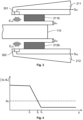
- Figure 4 shows a diagram exemplifying how the magnitude of the difference
- between the set gap distance d s and the determined gap distance d d may vary as a function of time t according to one embodiment of the invention.
- a brake action is effected, which at least involves moving the first and second pressing members 211 and 212 away A from the rotatable member 110.
- decreases gradually as said brake action progresses, and at a second point in time t 2 , the difference value falls below the tolerance interval d th .
- the brake action stops and the difference value levels out.
- the gear assembly 220 includes a load-cell sensor 250 configured to produce a force signal F reflecting the magnitude of a force applied by the first and second pressing members 211 and 212 respectively on the rotatable member 110. Namely, there is a direct and unambiguous relationship between this force and the gap distance d d .
- the brake sensor 235 is configured to determine the gap distance d d based on the force signal F.
- the load-cell sensor is symbolically indicated by reference numeral 250.
- a transducer of the load-cell sensor 250 is preferably arranged along at least one of a respective axis A1 and A2 around which each of the first and second pressing members 211 and 212 is pivotable.
- the brake sensor 235 is configured to determine the gap distance d d based on the magnitude of a current fed to the electric motor 230 and a period during which the current has been fed to the electric motor 230. This is especially advantageous if the electric motor 230 is of DC-motor type because for such motors there is a straightforward relationship between the magnitude of the supplied current, the extension of time during which the current has been supplied and the torque of the motor's power transmission shaft. The torque, in turn, is directly correlated with the determine the gap distance d d .
- the first and second pressing members 211 and 212 respectively contain at least one ultrasonic sensor, for example 301 and 302, each of which is configured to emit ultrasound energy Eus towards the rotatable member 110.
- the ultrasonic sensors are further configured to produce a respective ranging signal S R1 and S R2 based on reflections of the emitted ultrasound energy Eus against the rotatable member 110.
- the brake sensor 235 is configured to determine the gap distance d d , for example represented by one or both of distances d d1 and d d2 , based on the at least one ranging signal S R1 and/or S R2 .
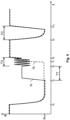
- the brake actuator 120 receives a brake command cmd B that represents full braking force, which is equivalent to a set gap distance d s equal to d FB .
- a brake command cmd B that represents full braking force
- the train vehicle 100 stays at a station. Due to the weather conditions, ice is formed on the braking system while the rail vehicle is stationary; and as a result, the first and second pressing members 211 and 212 become stuck against the rotatable member 110. Consequently, when at t 5 the brake actuator 120 receives a brake com-mand cmds that represents releasing of the brake and the set gap distance d s increases rapidly. However, the determined gap distance d d remains at the d FB level.
- the brake actuator 120 After expiry of a test period TT, at a point in time t 6 , the brake actuator 120 establishes that the magnitude of the difference
- a calibration procedure TC follows.
- this is illustrated by a full test braking at a point in time t 9 and a subsequent full brake release, which is completed at a point in time t 10 .
- the set and determined gap distances d s and d d match during the calibration procedure TC, which indicates that these measures are calibrated.
- the brake actuator 120 after producing the electric brake-force signal BF in such a way that the brake action at least involves moving the first and second pressing members 211 and 212 away A from the rotatable member 110, the brake actuator 120 is configured to establish the magnitude of the difference
- the brake actuator 120 is configured to receive a user-generated deactivation instruction cmd DNI , for example from a driver of the rail vehicle or a service technician. In response to the user-generated deactivation instruction cmd DNI , the brake actuator 120 is configured to regard the deicing criterion DI as not to be fulfilled.
- the brake actuator 120 is configured to generate an acknowledgement message ACK in response to regarding the deicing criterion DI as not to be fulfilled.
- the brake actuator 220 is connected to a first data bus 250 in the rail vehicle 200, which first data bus 250 is configured to communicate status messages SS.
- first data bus 250 is configured to communicate status messages SS.
- the brake actuator 220 is configured to forward the acknowledgment message ACK as a status message SS over the first data bus 250, for example to the driver's cabin.
- the rail vehicle 100 may also contain a second data bus 260, which is connected to the brake actuator 220 and which second data bus 260 is configured to communicate control signals CS, such as the brake command cmds to the brake actuator 220.
- the brake actuator 120 may further be configured to receive a user-generated activation instruction cmd DI in the form of a control signal CS over the second data bus 260.
- the brake actuator 120 In response to receiving the user-generated activation instruction cmd DI the brake actuator 120 is configured to regard the deicing criterion DI as fulfilled.
- an operator may manually initiate a deicing process if for example he/she foresees that this is appropriate.
- the second data bus 260 may also be used to forward the user-generated deactivation instruction cmd DNI to the brake actuator 12.
- the brake actuator 120 preferably includes processing circuitry and programmed memory units, the design of which will be briefly described below with reference to Figure 6 .
- Figure 6 shows a block diagram of the brake actuator 120 according to one embodiment of the invention.
- the brake actuator 120 includes processing circuitry in the form of at least one processor 630 and a memory unit 620, i.e. non-volatile data carrier, storing a computer program 625, which, in turn, contains software for making the at least one processor 630 execute the actions mentioned in this invention when the computer program 625 is run on the at least one processor 630.
- Figure 6 also illustrates the temperature sensor 640 and the controller 650.
- the temperature sensor 640 is configured to generate the temperature signal S T indicating the ambient temperature level to the at least one processor 630.
- the controller 650 is configured to generate a second trigger signal T2 repeatedly according to a time schedule, which second trigger signal T2 causes the deicing criterion DI to be fulfilled.
- Figure 6 shows a power input W, a respective connection to the first and second data buses 250 and 260 via which the acknowledgement message ACK is sent and the commands cmds, cmd NDI and cmd DI are received respectively.
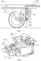
- a brake unit 200 having first and second pressing members 211 and 212 respectively, and a rotatable member 110 being mechanically linked to at least one wheel 105 of the rail vehicle 100.
- the brake unit is configured to receive the electric brake-force signal BF, and in response thereto cause the first and second pressing members 211 and 212 to execute the brake action with respect to the rotatable member 110.
- a step 710 it is checked whether a deicing criterion is fulfilled; and if so, a step 720 follows. Otherwise, the procedure loops back and stays in step 710.
- step 720 an electric brake-force signal is produced, which via an electric motor 230 and a gear assembly 220 in the brake unit 200 is configured to cause the first and second pressing members 211 and 212 to move away A from the rotatable member 110, so that any ice/snow on the braking system, especially surrounding the first and second pressing members 211 and 212, is expected to break and fall off.
- a step 730 follows in which it is checked whether the deicing criterion still is fulfilled. If so, the procedure loops back to step 720 for a continued deicing process; and otherwise, the procedure loops back to step 710.
- All of the process steps, as well as any sub-sequence of steps, described with reference to Figure 7 may be controlled by means of a programmed processor.
- the embodiments of the invention described above with reference to the drawings comprise processor and processes performed in at least one processor, the invention thus also extends to computer programs, particularly computer programs on or in a carrier, adapted for putting the invention into practice.
- the program may be in the form of source code, object code, a code intermediate source and object code such as in partially compiled form, or in any other form suitable for use in the implementation of the process according to the invention.
- the program may either be a part of an operating system, or be a separate application.
- the carrier may be any entity or device capable of carrying the program.
- the carrier may comprise a storage medium, such as a Flash memory, a ROM (Read Only Memory), for example a DVD (Digital Video/Versatile Disk), a CD (Compact Disc) or a semiconductor ROM, an EPROM (Erasable Programmable Read-Only Memory), an EEPROM (Electrically Erasable Programmable Read-Only Memory), or a magnetic recording medium, for example a floppy disc or hard disc.
- the carrier may be a transmissible carrier such as an electrical or optical signal which may be conveyed via electrical or optical cable or by radio or by other means.
- the carrier When the program is embodied in a signal, which may be conveyed, directly by a cable or other device or means, the carrier may be constituted by such cable or device or means.
- the carrier may be an integrated circuit in which the program is embedded, the integrated circuit being adapted for performing, or for use in the performance of, the relevant processes.
Landscapes
- Engineering & Computer Science (AREA)
- Transportation (AREA)
- Mechanical Engineering (AREA)
- Regulating Braking Force (AREA)
- Braking Systems And Boosters (AREA)
Claims (32)
- Bremssystem für ein Schienenfahrzeug (100), wobei das Bremssystem aufweist:einen Bremsaktuator (120), der konfiguriert ist, um einen Bremsbefehl (cmdB) zu empfangen und ansprechend darauf ein elektrisches Bremskraftsignal (BF), das eine Bremsaktion befiehlt, zu erzeugen, undeine Bremseinheit (200), die erste und zweite Druckelemente (211; 212) und ein drehbares Element (110), das mit wenigstens einem Rad (105) des Schienenfahrzeugs (100) mechanisch verbunden ist, aufweist, wobei die Bremseinheit (200) konfiguriert ist, um das elektrische Bremskraftsignal (BF) zu empfangen und ansprechend darauf zu bewirken, dass die ersten und zweiten Druckelemente (211; 212) die Bremsaktion in Bezug auf das drehbare Element (110) ausführen,wobei die Bremseinheit (200) ferner aufweist:eine Getriebeanordnung (220), die eingerichtet ist, um mechanisch auf die ersten und zweiten Druckelemente (211; 212) einzuwirken, undeinen Elektromotor (230), der konfiguriert ist, um ansprechend auf das elektrische Bremskraftsignal (BF) auf die Getriebeanordnung 220) einzuwirken, um zu bewirken, dass die ersten und zweiten Druckelemente (211; 212) sich auf das drehbare Element (110) zu (T) oder von diesem weg (A) bewegen, und dadurch gekennzeichnet, dassder Bremsaktuator (120) ferner konfiguriert ist, um das elektrische Bremskraftsignal (BF) auf eine derartige Weise zu erzeugen, dass die Bremsaktion ansprechend darauf, dass ein Enteisungskriterium (DI) erfüllt ist, das Bewegen der ersten und zweiten Druckelemente (211; 212) von dem drehbaren Element (110) weg bedingt, wobei der Bremsaktuator (120) konfiguriert ist, um, falls das Enteisungskriterium (DI) erfüllt ist, das elektrische Bremskraftsignal (BF) auf eine derartige Weise zu erzeugen, dass die Bremsaktion das Bewegen der ersten und zweiten Druckelemente (211; 212) auf das drehbare Element (110) zu (T) und von ihm weg (A) in einem schwingenden Bewegungsmuster bedingt.
- Bremssystem nach Anspruch 1, das einen Temperatursensor (640) aufweist, der konfiguriert ist, um ein Temperatursignal (ST), das einen Umgebungstemperaturpegel anzeigt, zu erzeugen, und der Bremsaktuator (120) konfiguriert ist, um:das Temperatursignal (ST) zu empfangen und, falls der Umgebungstemperaturpegel wenigstens während einer vordefinierten Zeitspanne niedriger als eine Schwellwerttemperatur ist,ein erstes Auslösersignal, das bewirkt, dass das Enteisungskriterium (DI) erfüllt ist, zu erzeugen.
- Bremssystem nach Anspruch 2, wobei der Temperatursensor (640) in den Bremsaktuator (120) integriert ist.
- Bremssystem nach einem der vorhergehenden Ansprüche, das eine Steuerung (650) aufweist, die konfiguriert ist, um wiederholt gemäß einem Zeitplan ein zweites Auslösersignal (T2) zu erzeugen, wobei das zweite Auslösersignal (T2) bewirkt, dass das Enteisungskriterium (DI) erfüllt ist.
- Bremssystem nach Anspruch 4, wobei die Steuerung (650) in den Bremsaktuator (120) integriert ist.
- Bremssystem nach einem der vorhergehenden Ansprüche, das einen Bremssensor (235) aufweist, der konfiguriert ist, um einen jeweiligen Spaltabstand (dai; dd2) zwischen Bremsbelägen (211b; 213b) der ersten und zweiten Druckelemente (211; 212) und dem drehbaren Element (110) zu bestimmen, und wobei der Bremsaktuator (120) ferner konfiguriert ist, um:
die bestimmten jeweiligen Spaltabstände (dai; dd2) mit einem festgelegten Spaltabstand (ds) zwischen den Bremsbelägen (211b; 213b) der ersten und zweiten Druckelemente (211; 212) und dem drehbaren Element (110) zu vergleichen, wobei der festgelegte Spaltabstand (ds) ein Parameter ist, der bei der Bremsaktion zugewiesen wird, und das Enteisungskriterium (DI) erfüllt ist, wenn der Betrag einer Differenz (|ds - dd|) zwischen dem festgelegten Spaltabstand und den jeweiligen bestimmten Spaltabständen ein Toleranzintervall (dth) überschreitet. - Bremssystem nach Anspruch 6, wobei:die Getriebeanordnung (220) einen Impulsgeber (225) aufweist, der konfiguriert ist, um ein Impulssignal (P#) zu erzeugen, das eine Positionsbeziehung zwischen den ersten und zweiten Druckelementen (211; 212) widerspiegelt, undder Bremssensor (235) konfiguriert ist, um den Spaltabstand (dd) basierend auf dem Impulssignal (P#) zu bestimmen.
- Bremssystem nach Anspruch 6, wobei:die Getriebeanordnung (220) einen Lastzellensensor (250) aufweist, der konfiguriert ist, um ein Kraftsignal (F) zu erzeugen, das den Betrag einer Kraft widerspiegelt, die von den ersten und zweiten Druckelementen (211; 212) auf das drehbare Element (110) angewendet wird, undder Bremssensor (235) konfiguriert ist, um den Spaltabstand (dd) basierend auf dem Kraftsignal (F) zu bestimmen.
- Bremssystem nach Anspruch 6, wobei:
der Bremssensor (235) konfiguriert ist, um den Spaltabstand (dd) basierend auf dem Betrag eines an den Elektromotor (230) gespeisten Stroms und einer Zeitspanne, während welcher der Elektromotor (230) mit dem Strom gespeist wurde, zu bestimmen. - Bremssystem nach Anspruch 6, wobei:die ersten und zweiten Druckelemente (211; 212) wenigstens einen Ultraschallsensor (301; 302) aufweisen, der konfiguriert ist, um Ultraschallenergie (Eus) zu emittieren und basierend auf Reflexionen der emittierten Ultraschallenergie (Eus) gegen das drehbare Element (110) wenigstens ein Entfernungsmessungssignal (SR1; SR2) zu erzeugen, undder Bremssensor (235) konfiguriert ist, um den Spaltabstand (dd) basierend auf dem wenigstens einen Entfernungsmessungssignal (SR1; SR2) zu bestimmen.
- Bremssystem nach einem der Ansprüche 6 bis 10, wobei der Bremsaktuator (120) nach der Erzeugung des elektrischen Bremskraftsignals (BF) auf eine derartige Weise, dass die Bremsaktion das Bewegen der ersten und zweiten Druckelemente (211; 212) weg (A) von dem drehbaren Element (110) bedingt, konfiguriert wird, um:
den Betrag der Differenz (|ds - dd|) zwischen dem festgelegten und den bestimmten Spaltabständen (ds; dd) festzustellen, und, falls der Betrag kleiner oder gleich dem Toleranzintervall (dth) ist, das Enteisungskriterium (DI) als nicht erfüllt zu betrachten. - Bremssystem nach einem der Ansprüche 6 bis 11, wobei der Bremsaktuator (120) konfiguriert ist, um:eine nutzererzeugte Deaktivierungsanweisung (cmdDNI) zu empfangen; und ansprechend daraufdas Enteisungskriterium (DI) als nicht erfüllt zu betrachten.
- Bremssystem nach einem der Ansprüche 11 oder 12, wobei der Bremsaktuator (120) konfiguriert ist, um ansprechend darauf, dass das Enteisungskriterium (DI) als nicht erfüllt betrachtet wird, eine Quittungsnachricht (ACK) zu erzeugen.
- Bremssystem nach Anspruch 13, wobei der Bremsaktuator (220) mit einem ersten Datenbus (250) in dem Schienenfahrzeug (200) verbunden ist, wobei der erste Datenbus (250) konfiguriert ist, um Statusnachrichten (SS) zu übermitteln.
- Bremssystem nach Anspruch 14, wobei der Bremsaktuator (220) konfiguriert ist, um die Quittungsnachricht (ACK) als eine Statusnachricht (SS) über den ersten Datenbus (250) weiterzuleiten.
- Bremssystem nach einem der vorhergehenden Ansprüche, wobei der Bremsaktuator (220) mit einem zweiten Datenbus (260) in dem Schienenfahrzeug (200) verbunden ist, wobei der zweite Datenbus (260) konfiguriert ist, um Steuersignale (CS) zu übermitteln.
- Bremssystem nach Anspruch 16, wobei der Bremsaktuator (220) konfiguriert ist, um den Bremsbefehl (cmdB) als ein Steuersignal über den zweiten Datenbus (260) zu empfangen.
- Bremssystem nach einem der vorhergehenden Ansprüche, wobei der Bremsaktuator (120) konfiguriert ist, um:eine nutzererzeugte Aktivierungsanweisung (cmdDI) zu empfangen; undansprechend darauf das Enteisungskriterium (DI) als erfüllt zu betrachten.
- Computerimplementiertes Verfahren zur Steuerung eines Bremssystems für ein Schienenfahrzeug (100), wobei das Bremssystem einen Bremsaktuator (120) aufweist, wobei das Verfahren von wenigstens einem Prozessor (630) in dem Bremsaktuator (120) ausgeführt wird und aufweist:Empfangen eines Bremsbefehls (cmdB) und ansprechend daraufErzeugen eines elektrischen Bremskraftsignals (BF), das eine Bremsaktion befiehlt,wobei das Bremssystem ferner eine Bremseinheit (200) mit ersten und zweiten Druckelementen (211; 212) und ein drehbares Element (110) aufweist, das mit wenigstens einem Rad (105) des Schienenfahrzeugs (100) mechanisch verbunden ist, wobei die Bremseinheit (200) konfiguriert ist, um das elektrische Bremskraftsignal (BF) zu empfangen und ansprechend darauf zu bewirken, dass die ersten und zweiten Druckelemente (211; 212) die Bremsaktion in Bezug auf das drehbare Element (110) ausführen, wobei die Bremseinheit (200) ferner eine Getriebeanordnung (220) aufweist, die eingerichtet ist, um mechanisch auf die ersten und zweiten Druckelemente (211; 212) einzuwirken, wobei das Bremssystem einen Elektromotor (230) aufweist, der konfiguriert ist, um ansprechend auf das elektrische Bremskraftsignal (BF) auf die Getriebeanordnung 220) einzuwirken, um zu bewirken, dass die ersten und zweiten Druckelemente (211; 212) sich auf das drehbare Element (110) zu (T) oder von diesem weg (A) bewegen, und wobei das Verfahren gekennzeichnet ist durch:Prüfen, ob ein Enteisungskriterium (DI) erfüllt ist und wenn das Kriterium erfüllt ist,Erzeugen des elektrischen Bremskraftsignals (BF) auf eine derartige Weise, dass die Bremsaktion das Bewegen der ersten und zweiten Druckelemente (211; 212) von dem drehbaren Element (110) weg (A) bedingt, wobei das Verfahren, falls das Enteisungskriterium (DI) erfüllt ist, aufweist:
Erzeugen des elektrischen Bremskraftsignals (BF) auf eine derartige Weise, dass die Bremsaktion das Bewegen der ersten und zweiten Druckelemente (211; 212) auf das drehbare Element (110) zu (T) und von ihm weg (A) in einem schwingenden Bewegungsmuster bedingt. - Verfahren nach Anspruch 19, das aufweist:Empfangen eines Temperatursignals (ST), das einen Umgebungstemperaturpegel anzeigt, und falls der Umgebungstemperaturpegel wenigstens während einer vordefinierten Zeitspanne niedriger als eine Schwellwerttemperatur ist,Erzeugen eines ersten Auslösersignals, das bewirkt, dass das Enteisungskriterium (DI) erfüllt ist.
- Verfahren nach Anspruch 19 oder 20, das aufweist:
wiederholtes Erzeugen eines zweiten Auslösersignals (T2) gemäß einem Zeitplan, wobei das zweite Auslösersignal (T2) bewirkt, dass das Enteisungskriterium (DI) erfüllt ist. - Verfahren nach einem der Ansprüche 19 bis 21, wobei das Bremssystem einen Bremssensor (235) aufweist, der konfiguriert ist, um einen jeweiligen Spaltabstand (dd1; dd2) zwischen Bremsbelägen (211b; 213b) der ersten und zweiten Druckelemente (211; 212) und dem drehbaren Element (110) zu bestimmen, und wobei das Verfahren aufweist:Vergleichen der bestimmten jeweiligen Spaltabstände (dd1; dd2) mit einem festgelegten Spaltabstand (ds) zwischen den Bremsbelägen (211b; 213b) der ersten und zweiten Druckelemente (211; 212) und dem drehbaren Element (110), wobei der festgelegte Spaltabstand (ds) ein Parameter ist, der bei der Bremsaktion zugewiesen wird, undals erfüllt Betrachten des Enteisungskriteriums (DI), wenn der Betrag einer Differenz (|ds - dd|) zwischen dem festgelegten Spaltabstand und den jeweiligen bestimmten Spaltabständen ein Toleranzintervall (dth) überschreitet.
- Verfahren nach Anspruch 22, wobei die Getriebeanordnung (220) einen Impulsgeber (225) aufweist, der konfiguriert ist, um ein Impulssignal (P#) zu erzeugen, das eine Positionsbeziehung zwischen den ersten und zweiten Druckelementen (211; 212) widerspiegelt, und wobei das Verfahren aufweist:
Bestimmen des Spaltabstands (dd) basierend auf dem Impulssignal (P#). - Verfahren nach Anspruch 22, wobei die Getriebeanordnung (220) einen Lastzellensensor (250) aufweist, der konfiguriert ist, um ein Kraftsignal (F) zu erzeugen, das den Betrag einer Kraft widerspiegelt, die von den ersten und zweiten Druckelementen (211; 212) auf das drehbare Element (110) angewendet wird, und wobei das Verfahren aufweist:
Bestimmen des Spaltabstands (dd) basierend auf dem Kraftsignal (F). - Verfahren nach Anspruch 22, das aufweist:
Bestimmen des Spaltabstands (dd) basierend auf dem Betrag eines an den Elektromotor (230) gespeisten Stroms und einer Zeitspanne, während welcher der Elektromotor (230) mit dem Strom gespeist wurde. - Verfahren nach Anspruch 22, wobei die ersten und zweiten Druckelemente (211; 212) wenigstens einen Ultraschallsensor (301; 302) aufweisen, der konfiguriert ist, um Ultraschallenergie (Eus) zu emittieren und basierend auf Reflexionen der emittierten Ultraschallenergie (Eus) gegen das drehbare Element (110) wenigstens ein Entfernungsmessungssignal (SR1; SR2) zu erzeugen, und wobei das Verfahren aufweist:
Bestimmen des Spaltabstands (dd) basierend auf dem wenigstens einen Entfernungsmessungssignal (SR1; SR2). - Verfahren einem der Ansprüche 22 bis 26, wobei das Verfahren nach der Erzeugung des elektrischen Bremskraftsignals (BF) auf eine derartige Weise, dass die Bremsaktion das Bewegen der ersten und zweiten Druckelemente (211; 212) weg (A) von dem drehbaren Element (110) bedingt, aufweist:Bestimmen des Betrags der Differenz (|ds - dd|) zwischen dem festgelegten und den bestimmten Spaltabständen (ds; dd) und falls der Betrag kleiner oder gleich dem Toleranzintervall (dth) ist,als nicht erfüllt Betrachten des Enteisungskriteriums (DI).
- Verfahren nach einem der Ansprüche 22 bis 27, das aufweist:Prüfen, ob eine nutzererzeugte Deaktivierungsanweisung (cmdDNI) empfangen wurde, und falls eine nutzererzeugte Deaktivierungsanweisung (cmdDNI) empfangen wurde,als nicht erfüllt Betrachten des Enteisungskriteriums (DI).
- Verfahren nach einem der Ansprüche 27 oder 28, das aufweist:
ansprechend darauf, dass das Enteisungskriterium (DI) nicht erfüllt ist, Erzeugen einer Quittungsnachricht (ACK). - Verfahren nach einem der Ansprüche 19 bis 29, das aufweist:Prüfen, ob eine nutzererzeugte Aktivierungsanordnung (cmdDI) empfangen wurde, und falls die nutzererzeugte Aktivierungsanweisung (cmdDI) empfangen wurde,als erfüllt Betrachten des Enteisungskriteriums (DI).
- Computerprogramm (625), das in einen nichtflüchtigen Datenträger (620), der kommunikationsfähig mit wenigstens einem Prozessor (630) verbunden ist, ladbar ist, wobei das Computerprogramm (625) Software aufweist, um das Verfahren nach einem der Ansprüche 19 bis 30 auszuführen, wenn das Computerprogramm (325) auf wenigstens einem Prozessor (330) laufen gelassen wird.
- Nichtflüchtiger Datenträger (620), der das Computerprogramm (625) nach Anspruch 31 enthält.
Priority Applications (5)
| Application Number | Priority Date | Filing Date | Title |
|---|---|---|---|
| ES22162522T ES3008664T3 (en) | 2022-03-16 | 2022-03-16 | Braking system, computer-implemented method of controlling a braking system of a rail vehicle, computer program and non-volatile data carrier |
| EP22162522.1A EP4245620B1 (de) | 2022-03-16 | 2022-03-16 | Bremssystem, computerimplementiertes verfahren zur steuerung eines bremssystems eines schienenfahrzeugs, computerprogramm und nichtflüchtiger datenträger |
| PCT/EP2022/088094 WO2023174575A1 (en) | 2022-03-16 | 2022-12-30 | Braking system, computer-implemented method of controlling a braking system of a rail vehicle, computer program and non-volatile data carrier |
| CN202280091896.1A CN118715148A (zh) | 2022-03-16 | 2022-12-30 | 制动系统、控制轨道车辆的制动系统的计算机实现的方法、计算机程序和非易失性数据载体 |
| US18/834,669 US12559078B2 (en) | 2022-03-16 | 2022-12-30 | Braking system, computer-implemented method of controlling a braking system of a rail vehicle, computer program and non-volatile data carrier |
Applications Claiming Priority (1)
| Application Number | Priority Date | Filing Date | Title |
|---|---|---|---|
| EP22162522.1A EP4245620B1 (de) | 2022-03-16 | 2022-03-16 | Bremssystem, computerimplementiertes verfahren zur steuerung eines bremssystems eines schienenfahrzeugs, computerprogramm und nichtflüchtiger datenträger |
Publications (3)
| Publication Number | Publication Date |
|---|---|
| EP4245620A1 EP4245620A1 (de) | 2023-09-20 |
| EP4245620B1 true EP4245620B1 (de) | 2025-01-29 |
| EP4245620C0 EP4245620C0 (de) | 2025-01-29 |
Family
ID=80785023
Family Applications (1)
| Application Number | Title | Priority Date | Filing Date |
|---|---|---|---|
| EP22162522.1A Active EP4245620B1 (de) | 2022-03-16 | 2022-03-16 | Bremssystem, computerimplementiertes verfahren zur steuerung eines bremssystems eines schienenfahrzeugs, computerprogramm und nichtflüchtiger datenträger |
Country Status (5)
| Country | Link |
|---|---|
| US (1) | US12559078B2 (de) |
| EP (1) | EP4245620B1 (de) |
| CN (1) | CN118715148A (de) |
| ES (1) | ES3008664T3 (de) |
| WO (1) | WO2023174575A1 (de) |
Family Cites Families (9)
| Publication number | Priority date | Publication date | Assignee | Title |
|---|---|---|---|---|
| FR2610053B1 (fr) * | 1987-01-22 | 1989-03-31 | Bendix France | Procede et dispositif d'actionnement d'un mecanisme de freinage par un moteur electrique rotatif |
| JPH0671947B2 (ja) | 1987-10-30 | 1994-09-14 | シャープ株式会社 | 給紙装置 |
| JP4719700B2 (ja) | 2007-02-13 | 2011-07-06 | 本田技研工業株式会社 | 電動駐車ブレーキ装置における凍結検出装置 |
| DE102014107402B4 (de) * | 2014-05-26 | 2021-11-04 | Knorr-Bremse Systeme für Schienenfahrzeuge GmbH | Schienenfahrzeugbremssystem mit einer Konditionierungseinrichtung, Konditionierungseinrichtung und Verfahren zum Betreiben einer Konditionierungseinrichtung |
| CN104006098A (zh) * | 2014-05-27 | 2014-08-27 | 长春轨道客车股份有限公司 | 适用于高寒环境下的动车组基础制动装置 |
| EP2995527B1 (de) * | 2014-09-10 | 2021-03-17 | ALSTOM Transport Technologies | Komprimierbares Füllstück für einen Bremssattel eines Schienenfahrzeuges |
| AT516356A1 (de) * | 2014-09-18 | 2016-04-15 | Siemens Ag Oesterreich | Verfahren und Betätigungsvorrichtung zur Enteisung eines Schienenfahrzeuges |
| CN206481022U (zh) * | 2017-02-28 | 2017-09-08 | 东北石油大学 | 一种高压输电线的除冰装置 |
| JP2020533933A (ja) | 2017-09-06 | 2020-11-19 | 北京天佑新轡高新技術有限公司Beijing Tianyouxinpei high−tech Co.,Ltd. | マイクロコンピュータ制御の電気機械制動システム |
-
2022
- 2022-03-16 EP EP22162522.1A patent/EP4245620B1/de active Active
- 2022-03-16 ES ES22162522T patent/ES3008664T3/es active Active
- 2022-12-30 WO PCT/EP2022/088094 patent/WO2023174575A1/en not_active Ceased
- 2022-12-30 US US18/834,669 patent/US12559078B2/en active Active
- 2022-12-30 CN CN202280091896.1A patent/CN118715148A/zh active Pending
Also Published As
| Publication number | Publication date |
|---|---|
| EP4245620A1 (de) | 2023-09-20 |
| US12559078B2 (en) | 2026-02-24 |
| CN118715148A (zh) | 2024-09-27 |
| US20250153699A1 (en) | 2025-05-15 |
| WO2023174575A1 (en) | 2023-09-21 |
| ES3008664T3 (en) | 2025-03-24 |
| EP4245620C0 (de) | 2025-01-29 |
Similar Documents
| Publication | Publication Date | Title |
|---|---|---|
| US10576956B2 (en) | Driver assistance system with increased reliability and availability | |
| JP4912670B2 (ja) | 電動ブレーキシステム | |
| US11713037B2 (en) | Controlling of a dual-processors type electrical parking device in event of emergency braking | |
| CN107921934B (zh) | 用于驾驶员辅助的方法和装置 | |
| KR20200085325A (ko) | 이중 중복을 갖는 자동차의 적어도 반자율 작동을 위한 시스템 | |
| US9340186B2 (en) | System for controlling the release of an automatic parking brake device onboard an automobile | |
| US12172617B2 (en) | Electronic parking brake system and control method thereof | |
| CN102407842B (zh) | 具有在控制仪停止运行后自动再校准功能的驻车制动器 | |
| US20220399849A1 (en) | Electronic parking brake system and control method therefor | |
| JP2006193147A (ja) | 電気ブレーキを備えた乗物用ブレーキシステムにおける保護方法 | |
| EP4126613B1 (de) | Betriebssicheres elektrisches bremssystem | |
| JP5453448B2 (ja) | ドライブトレインを制御する方法および装置 | |
| KR20210088684A (ko) | 제어 장치 | |
| EP4245620B1 (de) | Bremssystem, computerimplementiertes verfahren zur steuerung eines bremssystems eines schienenfahrzeugs, computerprogramm und nichtflüchtiger datenträger | |
| EP4124527B1 (de) | Bremsvorrichtung, verfahren zur bestimmung von abnormalem betrieb und programm zur bestimmung von abnormalem betrieb | |
| CN120813507A (zh) | 用于运行机动车辆的方法、控制装置、机动车辆 | |
| KR101417857B1 (ko) | 전자식 주차 브레이크 시스템의 제어 방법 | |
| EP4230486B1 (de) | Feststellbremsanlage, computerimplementiertes verfahren zur steuerung einer feststellbremsanlage eines schienenfahrzeugs, computerprogramm und nichtflüchtiger datenträger | |
| EP4663490A1 (de) | Bremssystem für ein schienenfahrzeug, computerimplementiertes verfahren, computerprogramm und nichtflüchtiger datenträger | |
| CN113306544B (zh) | 逆变器电路、逆变器控制装置以及车辆驱动装置 | |
| JP6545582B2 (ja) | 電動ブレーキ装置 | |
| EP4474233A1 (de) | Bremsaktuator, computerimplementiertes verfahren, computerprogramm, nichtflüchtiger datenträger und bremssystem für ein schienenfahrzeug | |
| US20260008442A1 (en) | Thermal management of electromechanical brake system using motor torque | |
| US20250388221A1 (en) | Automatic brake control to support propulsion system in electric vehicle | |
| KR20260041643A (ko) | 빙결 온도 이하에서의 주차 브레이크 조립체의 열 관리 |
Legal Events
| Date | Code | Title | Description |
|---|---|---|---|
| PUAI | Public reference made under article 153(3) epc to a published international application that has entered the european phase |
Free format text: ORIGINAL CODE: 0009012 |
|
| STAA | Information on the status of an ep patent application or granted ep patent |
Free format text: STATUS: THE APPLICATION HAS BEEN PUBLISHED |
|
| AK | Designated contracting states |
Kind code of ref document: A1 Designated state(s): AL AT BE BG CH CY CZ DE DK EE ES FI FR GB GR HR HU IE IS IT LI LT LU LV MC MK MT NL NO PL PT RO RS SE SI SK SM TR |
|
| STAA | Information on the status of an ep patent application or granted ep patent |
Free format text: STATUS: REQUEST FOR EXAMINATION WAS MADE |
|
| 17P | Request for examination filed |
Effective date: 20240227 |
|
| RBV | Designated contracting states (corrected) |
Designated state(s): AL AT BE BG CH CY CZ DE DK EE ES FI FR GB GR HR HU IE IS IT LI LT LU LV MC MK MT NL NO PL PT RO RS SE SI SK SM TR |
|
| GRAP | Despatch of communication of intention to grant a patent |
Free format text: ORIGINAL CODE: EPIDOSNIGR1 |
|
| STAA | Information on the status of an ep patent application or granted ep patent |
Free format text: STATUS: GRANT OF PATENT IS INTENDED |
|
| INTG | Intention to grant announced |
Effective date: 20241030 |
|
| GRAS | Grant fee paid |
Free format text: ORIGINAL CODE: EPIDOSNIGR3 |
|
| GRAA | (expected) grant |
Free format text: ORIGINAL CODE: 0009210 |
|
| STAA | Information on the status of an ep patent application or granted ep patent |
Free format text: STATUS: THE PATENT HAS BEEN GRANTED |
|
| AK | Designated contracting states |
Kind code of ref document: B1 Designated state(s): AL AT BE BG CH CY CZ DE DK EE ES FI FR GB GR HR HU IE IS IT LI LT LU LV MC MK MT NL NO PL PT RO RS SE SI SK SM TR |
|
| REG | Reference to a national code |
Ref country code: GB Ref legal event code: FG4D |
|
| REG | Reference to a national code |
Ref country code: CH Ref legal event code: EP |
|
| REG | Reference to a national code |
Ref country code: DE Ref legal event code: R096 Ref document number: 602022009929 Country of ref document: DE |
|
| REG | Reference to a national code |
Ref country code: IE Ref legal event code: FG4D |
|
| U01 | Request for unitary effect filed |
Effective date: 20250129 |
|
| U07 | Unitary effect registered |
Designated state(s): AT BE BG DE DK EE FI FR IT LT LU LV MT NL PT RO SE SI Effective date: 20250204 |
|
| REG | Reference to a national code |
Ref country code: ES Ref legal event code: FG2A Ref document number: 3008664 Country of ref document: ES Kind code of ref document: T3 Effective date: 20250324 |
|
| U20 | Renewal fee for the european patent with unitary effect paid |
Year of fee payment: 4 Effective date: 20250415 |
|
| PG25 | Lapsed in a contracting state [announced via postgrant information from national office to epo] |
Ref country code: RS Free format text: LAPSE BECAUSE OF FAILURE TO SUBMIT A TRANSLATION OF THE DESCRIPTION OR TO PAY THE FEE WITHIN THE PRESCRIBED TIME-LIMIT Effective date: 20250429 |
|
| PG25 | Lapsed in a contracting state [announced via postgrant information from national office to epo] |
Ref country code: PL Free format text: LAPSE BECAUSE OF FAILURE TO SUBMIT A TRANSLATION OF THE DESCRIPTION OR TO PAY THE FEE WITHIN THE PRESCRIBED TIME-LIMIT Effective date: 20250129 |
|
| PGFP | Annual fee paid to national office [announced via postgrant information from national office to epo] |
Ref country code: ES Payment date: 20250625 Year of fee payment: 4 |
|
| PG25 | Lapsed in a contracting state [announced via postgrant information from national office to epo] |
Ref country code: IS Free format text: LAPSE BECAUSE OF FAILURE TO SUBMIT A TRANSLATION OF THE DESCRIPTION OR TO PAY THE FEE WITHIN THE PRESCRIBED TIME-LIMIT Effective date: 20250529 Ref country code: NO Free format text: LAPSE BECAUSE OF FAILURE TO SUBMIT A TRANSLATION OF THE DESCRIPTION OR TO PAY THE FEE WITHIN THE PRESCRIBED TIME-LIMIT Effective date: 20250429 |
|
| PG25 | Lapsed in a contracting state [announced via postgrant information from national office to epo] |
Ref country code: HR Free format text: LAPSE BECAUSE OF FAILURE TO SUBMIT A TRANSLATION OF THE DESCRIPTION OR TO PAY THE FEE WITHIN THE PRESCRIBED TIME-LIMIT Effective date: 20250129 |
|
| PG25 | Lapsed in a contracting state [announced via postgrant information from national office to epo] |
Ref country code: GR Free format text: LAPSE BECAUSE OF FAILURE TO SUBMIT A TRANSLATION OF THE DESCRIPTION OR TO PAY THE FEE WITHIN THE PRESCRIBED TIME-LIMIT Effective date: 20250430 |
|
| PG25 | Lapsed in a contracting state [announced via postgrant information from national office to epo] |
Ref country code: SM Free format text: LAPSE BECAUSE OF FAILURE TO SUBMIT A TRANSLATION OF THE DESCRIPTION OR TO PAY THE FEE WITHIN THE PRESCRIBED TIME-LIMIT Effective date: 20250129 |
|
| PG25 | Lapsed in a contracting state [announced via postgrant information from national office to epo] |
Ref country code: MC Free format text: LAPSE BECAUSE OF FAILURE TO SUBMIT A TRANSLATION OF THE DESCRIPTION OR TO PAY THE FEE WITHIN THE PRESCRIBED TIME-LIMIT Effective date: 20250129 |
|
| PG25 | Lapsed in a contracting state [announced via postgrant information from national office to epo] |
Ref country code: CZ Free format text: LAPSE BECAUSE OF FAILURE TO SUBMIT A TRANSLATION OF THE DESCRIPTION OR TO PAY THE FEE WITHIN THE PRESCRIBED TIME-LIMIT Effective date: 20250129 |
|
| REG | Reference to a national code |
Ref country code: CH Ref legal event code: H13 Free format text: ST27 STATUS EVENT CODE: U-0-0-H10-H13 (AS PROVIDED BY THE NATIONAL OFFICE) Effective date: 20251023 |
|
| PG25 | Lapsed in a contracting state [announced via postgrant information from national office to epo] |
Ref country code: SK Free format text: LAPSE BECAUSE OF FAILURE TO SUBMIT A TRANSLATION OF THE DESCRIPTION OR TO PAY THE FEE WITHIN THE PRESCRIBED TIME-LIMIT Effective date: 20250129 |
|
| PLBE | No opposition filed within time limit |
Free format text: ORIGINAL CODE: 0009261 |
|
| STAA | Information on the status of an ep patent application or granted ep patent |
Free format text: STATUS: NO OPPOSITION FILED WITHIN TIME LIMIT |
|
| 26N | No opposition filed |
Effective date: 20251030 |
|
| PG25 | Lapsed in a contracting state [announced via postgrant information from national office to epo] |
Ref country code: CH Free format text: LAPSE BECAUSE OF NON-PAYMENT OF DUE FEES Effective date: 20250331 |
|
| PG25 | Lapsed in a contracting state [announced via postgrant information from national office to epo] |
Ref country code: IE Free format text: LAPSE BECAUSE OF NON-PAYMENT OF DUE FEES Effective date: 20250316 |
|
| PGFP | Annual fee paid to national office [announced via postgrant information from national office to epo] |
Ref country code: GB Payment date: 20260317 Year of fee payment: 5 |
|
| U20 | Renewal fee for the european patent with unitary effect paid |
Year of fee payment: 5 Effective date: 20260311 |