EP4126613B1 - Betriebssicheres elektrisches bremssystem - Google Patents
Betriebssicheres elektrisches bremssystem Download PDFInfo
- Publication number
- EP4126613B1 EP4126613B1 EP21717243.6A EP21717243A EP4126613B1 EP 4126613 B1 EP4126613 B1 EP 4126613B1 EP 21717243 A EP21717243 A EP 21717243A EP 4126613 B1 EP4126613 B1 EP 4126613B1
- Authority
- EP
- European Patent Office
- Prior art keywords
- control
- brake
- backup
- primary
- branch
- Prior art date
- Legal status (The legal status is an assumption and is not a legal conclusion. Google has not performed a legal analysis and makes no representation as to the accuracy of the status listed.)
- Active
Links
Images


Classifications
-
- B—PERFORMING OPERATIONS; TRANSPORTING
- B60—VEHICLES IN GENERAL
- B60T—VEHICLE BRAKE CONTROL SYSTEMS OR PARTS THEREOF; BRAKE CONTROL SYSTEMS OR PARTS THEREOF, IN GENERAL; ARRANGEMENT OF BRAKING ELEMENTS ON VEHICLES IN GENERAL; PORTABLE DEVICES FOR PREVENTING UNWANTED MOVEMENT OF VEHICLES; VEHICLE MODIFICATIONS TO FACILITATE COOLING OF BRAKES
- B60T13/00—Transmitting braking action from initiating means to ultimate brake actuator with power assistance or drive; Brake systems incorporating such transmitting means, e.g. air-pressure brake systems
- B60T13/10—Transmitting braking action from initiating means to ultimate brake actuator with power assistance or drive; Brake systems incorporating such transmitting means, e.g. air-pressure brake systems with fluid assistance, drive, or release
- B60T13/66—Electrical control in fluid-pressure brake systems
- B60T13/662—Electrical control in fluid-pressure brake systems characterised by specified functions of the control system components
-
- B—PERFORMING OPERATIONS; TRANSPORTING
- B60—VEHICLES IN GENERAL
- B60T—VEHICLE BRAKE CONTROL SYSTEMS OR PARTS THEREOF; BRAKE CONTROL SYSTEMS OR PARTS THEREOF, IN GENERAL; ARRANGEMENT OF BRAKING ELEMENTS ON VEHICLES IN GENERAL; PORTABLE DEVICES FOR PREVENTING UNWANTED MOVEMENT OF VEHICLES; VEHICLE MODIFICATIONS TO FACILITATE COOLING OF BRAKES
- B60T13/00—Transmitting braking action from initiating means to ultimate brake actuator with power assistance or drive; Brake systems incorporating such transmitting means, e.g. air-pressure brake systems
- B60T13/74—Transmitting braking action from initiating means to ultimate brake actuator with power assistance or drive; Brake systems incorporating such transmitting means, e.g. air-pressure brake systems with electrical assistance or drive
- B60T13/741—Transmitting braking action from initiating means to ultimate brake actuator with power assistance or drive; Brake systems incorporating such transmitting means, e.g. air-pressure brake systems with electrical assistance or drive acting on an ultimate actuator
-
- B—PERFORMING OPERATIONS; TRANSPORTING
- B60—VEHICLES IN GENERAL
- B60T—VEHICLE BRAKE CONTROL SYSTEMS OR PARTS THEREOF; BRAKE CONTROL SYSTEMS OR PARTS THEREOF, IN GENERAL; ARRANGEMENT OF BRAKING ELEMENTS ON VEHICLES IN GENERAL; PORTABLE DEVICES FOR PREVENTING UNWANTED MOVEMENT OF VEHICLES; VEHICLE MODIFICATIONS TO FACILITATE COOLING OF BRAKES
- B60T17/00—Component parts, details, or accessories of power brake systems not covered by groups B60T8/00, B60T13/00 or B60T15/00, or presenting other characteristic features
- B60T17/18—Safety devices; Monitoring
- B60T17/22—Devices for monitoring or checking brake systems; Signal devices
- B60T17/221—Procedure or apparatus for checking or keeping in a correct functioning condition of brake systems
-
- B—PERFORMING OPERATIONS; TRANSPORTING
- B60—VEHICLES IN GENERAL
- B60T—VEHICLE BRAKE CONTROL SYSTEMS OR PARTS THEREOF; BRAKE CONTROL SYSTEMS OR PARTS THEREOF, IN GENERAL; ARRANGEMENT OF BRAKING ELEMENTS ON VEHICLES IN GENERAL; PORTABLE DEVICES FOR PREVENTING UNWANTED MOVEMENT OF VEHICLES; VEHICLE MODIFICATIONS TO FACILITATE COOLING OF BRAKES
- B60T2270/00—Further aspects of brake control systems not otherwise provided for
- B60T2270/20—ASR control systems
- B60T2270/206—Monitoring, e.g. parameter monitoring, plausibility check
-
- B—PERFORMING OPERATIONS; TRANSPORTING
- B60—VEHICLES IN GENERAL
- B60T—VEHICLE BRAKE CONTROL SYSTEMS OR PARTS THEREOF; BRAKE CONTROL SYSTEMS OR PARTS THEREOF, IN GENERAL; ARRANGEMENT OF BRAKING ELEMENTS ON VEHICLES IN GENERAL; PORTABLE DEVICES FOR PREVENTING UNWANTED MOVEMENT OF VEHICLES; VEHICLE MODIFICATIONS TO FACILITATE COOLING OF BRAKES
- B60T2270/00—Further aspects of brake control systems not otherwise provided for
- B60T2270/40—Failsafe aspects of brake control systems
- B60T2270/402—Back-up
-
- B—PERFORMING OPERATIONS; TRANSPORTING
- B60—VEHICLES IN GENERAL
- B60T—VEHICLE BRAKE CONTROL SYSTEMS OR PARTS THEREOF; BRAKE CONTROL SYSTEMS OR PARTS THEREOF, IN GENERAL; ARRANGEMENT OF BRAKING ELEMENTS ON VEHICLES IN GENERAL; PORTABLE DEVICES FOR PREVENTING UNWANTED MOVEMENT OF VEHICLES; VEHICLE MODIFICATIONS TO FACILITATE COOLING OF BRAKES
- B60T2270/00—Further aspects of brake control systems not otherwise provided for
- B60T2270/40—Failsafe aspects of brake control systems
- B60T2270/404—Brake-by-wire or X-by-wire failsafe
-
- B—PERFORMING OPERATIONS; TRANSPORTING
- B60—VEHICLES IN GENERAL
- B60T—VEHICLE BRAKE CONTROL SYSTEMS OR PARTS THEREOF; BRAKE CONTROL SYSTEMS OR PARTS THEREOF, IN GENERAL; ARRANGEMENT OF BRAKING ELEMENTS ON VEHICLES IN GENERAL; PORTABLE DEVICES FOR PREVENTING UNWANTED MOVEMENT OF VEHICLES; VEHICLE MODIFICATIONS TO FACILITATE COOLING OF BRAKES
- B60T2270/00—Further aspects of brake control systems not otherwise provided for
- B60T2270/40—Failsafe aspects of brake control systems
- B60T2270/406—Test-mode; Self-diagnosis
-
- B—PERFORMING OPERATIONS; TRANSPORTING
- B60—VEHICLES IN GENERAL
- B60T—VEHICLE BRAKE CONTROL SYSTEMS OR PARTS THEREOF; BRAKE CONTROL SYSTEMS OR PARTS THEREOF, IN GENERAL; ARRANGEMENT OF BRAKING ELEMENTS ON VEHICLES IN GENERAL; PORTABLE DEVICES FOR PREVENTING UNWANTED MOVEMENT OF VEHICLES; VEHICLE MODIFICATIONS TO FACILITATE COOLING OF BRAKES
- B60T2270/00—Further aspects of brake control systems not otherwise provided for
- B60T2270/40—Failsafe aspects of brake control systems
- B60T2270/413—Plausibility monitoring, cross check, redundancy
Definitions
- the present disclosure relates to an electric brake system, method of controlling the system, controller or software for such system, and vehicle comprising the brake system.
- Brake-by-wire is typically used to denote a braking system in which the actuation and transmission devices are decoupled from each other.
- the brake pedal is the actuator and the hydraulic is the transmission device.
- electrohydraulic brake electro-pneumatic brake (in trucks)
- the electric brake Only the omission of the hydraulic or pneumatic makes the brake a real, so-called “dry" brake-by-wire application, since no fluid technology systems are used here.
- One reason for wanting to use this technology may be the slowness of currently used media in a brake system. With the help of pure electromechanical solutions, shorter response times may be achieved, which may also be reflected in the achievable braking distances.
- Another advantage may be a more favorable manufacturability of the brake-by-wire technology, since components in use in hydraulic systems such as a master cylinder, brake booster and an anti-lock component or more generally a brake modulation component are expensive to make, in comparison.
- An electric vehicle brake typically has an electromechanical actuation device, configured to press a friction brake lining for braking against a brake body that is fixed against relative rotation to a vehicle wheel.
- the brake body is typically a brake disc or a brake drum.
- the actuation device typically has an electric motor and a rotation-to-translation conversion gear that converts a rotary driving motion of the electric motor into a translational motion for pressing the friction brake lining against the brake body.
- Worm gears such as spindle gears or roller worm drives, are often used as rotation-to-translation conversion gears. It is also possible to convert the rotary motion into a translational motion by means of a pivotable cam, for instance.
- a step-down gear for instance in the form of a planetary gear, is often placed between the electric motor and the rotation-to-translation conversion gear.
- Self-boosting electromechanical vehicle brakes have a self booster that converts a frictional force, exerted by the rotating brake body against the friction brake lining that is pressed for braking against the brake body, into a contact pressure, which presses the friction brake lining against the brake body in addition to a contact pressure that is exerted by the actuation device.
- Wedge, ramp, and lever mechanisms are suitable for the self boosting.
- a control unit for an electric vehicle brake is reliable in that the risk of failure is limited to a minimum and that an occurrence of a failure does not immediately has serious consequences.
- the failure risk has a systematic aspect and a random aspect.
- the probability that an electronic component fails is strongly determined by the conditions during development and manufacturing. It is possible to reduce the probability by a proper development methodology, proper testing and verification and by providing for redundancy. Nevertheless failures due to random errors can never be fully excluded..
- the probability of a random failure is specified by the metric PMHF (Probability Metric of Random Hardware Failures). This metric indicates the probability density (h -1 ) of occurrence of a failure. A related metric is expressed in FIT units.
- ASIL-D has the highest ranking with a PMHF value ⁇ 10 -8 h -1 corresponding to 10 FIT.
- ASIL-C has a PMHF value ⁇ 10 -7 h -1 corresponding to 100 FIT and so on.
- the potential impact of a failure is further determined by the following aspects "severity”, “exposure” and “controllability” as becomes apparent from the following example wherein a brake control unit is provided to control an electric brake for each wheel in response to an external brake control signal from a driver.
- An exemplary failure is that the brake control unit fails to control one of the electric brakes when it receives the brake control signal. This involves the hazard that the vehicle has to much yaw and/or lateral movement.
- S3 The severity for this situation is indicated as S3, as the vehicle may become unstable and can run into the other lane of the road, therewith causing a crash with other traffic or objects.
- the exposure thereof is rated as E4, as it is a very common driving scenario.
- a known approach to reduce the potential impact of a random failure is to provide the brake control unit as a so-called "1002 (one-out-of-two) system".
- a brake control unit of this type has a dual control channel each with its own auto-diagnostic unit. Examples are provided in US 2013/282249 A1 and US2018056961 .
- US 2013/282249 A1 pertains to an electronic controller for a brake system of a motor vehicle, which comprises at least one interface to a control element, in particular a parking brake control switch, and at least two drive circuits for electric actuators, in particular electric parking brake actuators.
- the electronic controller comprises two or a plurality of independent arithmetic units, which are directly connected to each other via a data bus.
- a motor vehicle equipped with a controller or brake system according to the invention requires no transmission lock in an automatic gearbox.
- Cited document US2018056961 discloses a brake by wire system.
- the abstract specifies that a vehicle includes a plurality of electronic brake system (EBS) controllers configured to detect at least one braking event, and a plurality of brake assemblies.
- Each brake assembly is coupled to a respective wheel of the vehicle and includes an enhanced smart actuator.
- the enhanced smart actuator further includes an electro-mechanical actuator, and at least one power circuit.
- the electro-mechanical actuator is configured to adjust a torque force applied to the respective wheel.
- the at least one electronic power circuit is configured to output a high-frequency switched high-power current drive signal that drives the electro-mechanical actuator.
- the EBS controllers control a first group of enhanced smart actuators independently from a second group of enhanced smart actuators that exclude the enhanced smart actuators of the first group.
- US 2018/194353 A1 discloses a vehicle including a fault-tolerant braking system that controls a brake assembly which is configured to adjust a braking force applied to one or more wheels.
- the fault-tolerant braking system further includes a brake-by-wire (BBW) system and a vehicle control module (VCM).
- the BBW system is configured to control the brake assembly in response to a braking request.
- the VCM is configured to detect a fault of at least one of the brake assembly and the BBW system. In response to detecting the fault, the VCM selectively operates the vehicle between a normal operating mode and at least one degraded driving mode that limits operation of at least one of the vehicle engine and the vehicle transmission compared to the normal operating mode.
- aspects of the present disclosure relate to a brake control unit that comprises a primary control branch, a backup control branch, diagnostic utilities and mode control utilities.
- the primary control branch has a primary inverter and a primary control module to control operation of the primary inverter.
- the backup control branch has a backup inverter and a backup control module to control operation of the backup inverter.
- the diagnostic utilities are configured to determine an integrity status of both control branches.
- the integrity status indicates whether or not a control branch meets integrity requirements.
- the integrity requirements are not met by a control branch if it is determined that it is dysfunctional in operation (i.e. does not function or functions with errors).
- the integrity requirements of a control branch also are not met if it is not in operation, but if it is likely or certain that it will be dysfunctional when set to its operational state.
- the mode control utilities are configured to select in accordance with said determination an operational mode of the brake control unit from a plurality of potential operational modes comprising at least one of a normal operational mode and a degraded operational mode.
- the primary control branch In the normal operational mode the primary control branch is configured to generate a brake motor drive signal with its inverter controlled by its control module in response to an external brake control signal, In the degraded operational mode the backup control branch is configured to generate the brake motor drive signal with its inverter being controlled by its control module in response to the external brake control signal.
- the primary control module includes at least a first and a second mutually cooperating primary control component that are part of said diagnostic utilities in that they are configured to diagnose each others integrity status.
- the primary control module also comprises diagnostic utilities configured to diagnose an integrity status of the backup control branch by verifying a response signal of the backup control branch in response to a test signal.
- the first and a second mutually cooperating primary control component diagnose each others integrity status by a Q&A watchdog procedure.
- a first one of the primary control components periodically transmits a question message that requests a second one of the primary control components to perform a fixed series of arithmetic operations on a token value conveyed with the question message and to respond with a return message that conveys the resulting token value within a predetermined time-interval. If the resulting token value deviates from an expected token value, or is not received within the specified time interval by the first one of the primary control components that first one determines that the second one fails integrity requirements.
- the second one is also configured to determine that the first one fails integrity requirements if it does not receive a question message in a predetermined time-interval.
- the Q&A watchdog procedure is performed in a reciprocal manner in that both primary control components are configured to verify each others operation in this manner.
- the first and the second mutually cooperating primary control component each perform respective functions to compute the control signal for the primary inverter in accordance with the external brake control signal.
- the mutually cooperating control components are used in a cost effective manner, as they ach have clear distinctive contribution to the operation of the primary control module.
- one of these primary control components is a microcontroller that directly or indirectly controls the drive signals for the inverter as part of a feedback loop responsive to a motor angle sensor.
- another one of the primary control components is a power management controller.
- Similar Q&A watchdog procedures are applied with a larger number of primary control components. In this way it is possible not only to signal an error condition, but also to determine with more certainty which of the primary control components is actually suffering from a lack of integrity.
- a primary control module having a first, a second and a third primary control component, if it is the case that the second and the third primary control component both diagnose a lack of integrity in the first primary control component and further confirm each others integrity it is likely that the first primary control component indeed has a potential defect.
- the potential impact of a failure is strongly reduced.
- the brake motor is controlled by the primary brake control branch.
- this primary control branch is provided with auto-diagnostic utilities, the primary control branch functions with high integrity. Should nevertheless a failure occur in the primary control branch then the mode control utilities will enable the backup control branch to take over control.
- the primary control module further comprises diagnostic utilities configured to diagnose an integrity status of the backup control branch by verifying a response signal of said branch in response to a test signal. This enables the primary control module to confirm that the backup control branch indeed is available for taking over brake control in case of a primary control branch failure. Due to the fact that the failure of the primary control branch does not directly influence the vehicle behavior, the potential impact is strongly reduced.
- the mode control utilities alert the driver when changing the operation of the brake control unit to the degraded operational mode, so that the driver can take adequate steps, e.g. to drive to a garage or to reduce vehicle speed.
- the mode control utilities alert the driver when changing the operation of the brake control unit to the degraded operational mode, so that the driver can take adequate steps, e.g. to drive to a garage or to reduce vehicle speed.
- the mode control utilities alert the driver when changing the operation of the brake control unit to the degraded operational mode, so that the driver can take adequate steps, e.g. to drive to a garage or to reduce vehicle speed.
- an alternative or additional option measures are provided that directly change the operation of the vehicle to impose safer driving conditions or to prevent further driving as will be set out in more detail below. Due to the fact that backup control branch is only provided to temporarily control the brake in case of a failure of the primary control branch and the fact that its integrity is checked periodically or continuously during normal operation, a lower level of integrity is sufficient for the backup control branch. It does for example not
- the mode control utilities are configured to keep the backup control module operational during the normal operational mode, and the diagnostic utilities are configured to compare the response signal of the backup control branch with a reference response signal and reporting a lack of integrity of the backup control branch if it determines a substantial difference between said response signal and said reference response signal.
- the test signal is for example the external brake control signal. If the diagnostic means of the primary control branch determine that signals occurring in the backup control branch deviate significantly from corresponding signals in the primary control branch it determines a lack of integrity of the backup control branch.
- the response signal to be compared for example is indicative for a control signal provided by the backup control module to the backup inverter.
- the diagnostic utilities compares this with a reference response signal that is indicative for a control signal provided by the primary control module to the primary inverter.
- the mode control utilities are configured to enable both the primary control branch and the backup control branch to generate a brake motor drive signal.
- the brake control unit further comprises a respective phase cutoff switch that is controlled by the mode control utilities to select the brake motor drive signal from the primary control branch in the normal operational mode and to select the brake motor drive signal from the backup control branch in the degraded operational mode.
- a signal indicative for the brake motor drive signal provided by the backup control branch is suitable as a response signal.
- a signal indicative for the brake motor drive signal provided by the primary control branch is suitable as a reference signal.
- the set of potential operational modes further comprises a power-up mode in which the diagnostic utilities provide a control signal to the backup control branch to cause the backup control branch to generate a brake motor drive signal.
- the mode control utilities temporarily enable the backup control branch to drive a brake motor with the brake motor drive signal.
- the diagnostic utilities diagnose an operation of the backup control branch by verifying an operation of the brake motor in response to said the brake motor drive signal. In these embodiments, it is regularly verified that the backup control unit actually succeeds in properly controlling the brake motor. In some embodiments, this diagnostic procedure is combined with other diagnostic procedures, e.g. by comparing a response signal of the back-up backup control branch with a reference signal during normal operation as described above.
- the plurality of potential operational modes includes a further degraded operational mode.
- the mode control utilities select the primary control branch as the source of the brake motor drive signal.
- the mode control utilities select the further degraded operational mode if the diagnostic utilities determine a lack of integrity with the backup control branch, but determine that the primary control branch meets integrity requirements.
- the mode control utilities in some embodiments provide a signal to the driver and/or enforce safety restrictions to other control functions of the vehicle.
- the mode control utilities in some embodiments fully disable operation of the backup control branch to avoid any potential interference with the operation of the primary control branch.
- limited auto diagnostic capabilities are provided therein, including one or more of checksum verification and detection of out-of bound signals.
- the at least a first and a second mutually cooperating primary control component that are configured to diagnose each others integrity status for example comprise a power management controller and a micro controller responsible for feedback control of the motor. Accordingly each of the primary control components in the primary control branch has a distinct functionality and in addition has the function to diagnose the other one. A further extension is possible, wherein more than two primary control components are provided and each primary control component is configured to diagnose each others integrity.
- a brake control unit as described above and an electric brake controlled by the brake control unit form an electric brake control system.
- an electric brake control system for a vehicle comprises for each wheel such an electric brake controlled by a respective brake control unit.
- the brake control units mutually cooperate.
- a brake control unit is part of a vehicle control system that has one or more additional control units to control additional vehicle functions and wherein the brake control unit is configured to change an operational mode of at least one of said one or more additional control units in accordance with its own operational mode.
- the vehicle control system further comprises a speed control unit for controlling a speed of the vehicle.
- the brake control unit imposes a maximum on the speed with which the speed control unit is enabled to drive the vehicle if the operational mode of the brake control unit is not the normal operational mode. Therewith the potential impact should it be the case that also a backup control branch failure occurs is strongly reduced.
- the restricted driving speed would better enable the driver to control the behavior of the vehicle by steering actions.
- the maximum driving speed is gradually reduced to the restricted speed upon a transition from the normal operational mode to a degraded operational mode, so that the driver is not surprised and has the opportunity to properly respond.
- the maximum driving speed is reduced from the previous maximum to the restricted maximum in a time interval of a minute. Should it be the case that the current vehicle speed at the time of leaving the normal operational mode already is lower than the restricted maximum speed, then it is not necessary to impose a delay on restricting the maximum speed.
- a driver having noticed a warning signal and/or experiencing the restricted maximum speed may be expected to drive the vehicle to the garage to have the brake control unit repaired or replaced once it is no longer in the normal operational mode.
- the brake control unit is configured in some embodiments to cause the vehicle control system to discontinue vehicle operation upon determining that a predetermined time interval has lapsed and/or a predetermined distance was driven with the vehicle since its operational mode was no longer the normal operational mode.
- discontinuation takes place gradually, e.g. by gradually reducing the maximum speed to 0.
- a discontinuation is effected when the vehicle is at standstill. I.e. if the driver has parked the car and switched off power, further use is disabled, until the car is towed to the garage for repair or replacement of the brake control unit.
- a method of controlling a brake motor of a vehicle as provided herein comprises generating a brake motor drive signal in response to an external brake control signal.
- the external brake control signal typically originates from a control element for control by the driver, such as a brake pedal or a manually controlled element.
- the external brake control signal is issued by a component in an autonomous driving system.
- the external brake control signal is issued either under control by the driver or by a component in a semi-autonomous driving system.
- the method provided herein more particularly comprises:
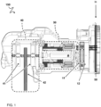
- FIG. 1 illustrates an electric brake system 150.
- the brake system 150 comprises or couples to an electric brake motor 12 which transmits mechanical energy to a brake mechanism 40 via a brake transmission 30.
- the electric brake motor 12 is configured to transduce electrical power into mechanical power.
- An electric motor is understood as a machine that converts electrical energy into mechanical energy.
- the electric motor operates through interaction between the motor's magnetic field and electric current in a wire winding to generate force in the form of rotation of an output shaft.
- the system comprises or is coupled to a brake mechanism 40 configured to apply braking to a wheel of a vehicle, or release braking of the wheel, depending on a mechanical state of the brake mechanism 40.
- the mechanical state of the brake mechanism 40 is configured to vary anywhere between a (maximum) braked state, and a (fully) released state in which no braking is applied, or intermediate states in which at least some braking is applied.
- a brake transmission 30 is configured to transmit the mechanical power from the electric brake motor 12 to the brake mechanism 40.
- the brake transmission 30 comprises a self-locking mechanism.
- the locking mechanism is configured to maintain the mechanical state of the brake mechanism 40 in absence of the electrical power to the electric brake motor 12.
- self-locking occurs when the brake transmission is in a static state - i.e. not moving.
- the brake transmission comprises a worm gear. Without being bound by theory, as long as a coefficient of friction between the gear and the worm is larger than the tangent of the worm's lead angle, the worm gear can be considered self-locking and will not back drive. Of course also other self-locking mechanisms are suitable.
- the brake system comprises a piston-type mechanism, but also other mechanisms (e.g. a floating type caliper brake) are suitable.
- the brake illustrated in FIG. 1 is an example of a floating type caliper brake.
- the brake transmission comprises a set of gears which are operationally connected to an output axle of the brake motor 12.
- gears in the brake transmission are configured to drive a spindle which is housed in a spindle nut to move a piston.
- the piston in turn is guided, e.g. by guide pins to drive the opening and closing movements of a caliper 41 which can be considered part of the brake mechanism 40.
- the caliper is fitted with two opposing brake pads.
- the caliper 41 is fixed to a bracket by which the caliper 41 is to be suspended over a brake disc 42 of a wheel such that the brake disc is provided between the pads of the caliper.
- the brake disc 42 is connected to at least one wheel of the vehicle, e.g. on a wheel axle directly connected to the wheel and brake disc.
- a primary gear 11 is operationally connected to rotate with the brake transmission 30. For example, while braking is applied to the wheel via the brake transmission the primary gear 11 is rotated in a brake applying direction "D1". For example, while braking of the wheel is released, the primary gear 11 is rotated in an opposite, brake releasing direction "D2".
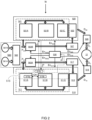
- FIG. 2 schematically shows a brake control unit 50 comprising a primary control branch 510, a backup control branch 520, diagnostic utilities 515 and mode control utilities 530.
- the primary control branch 510 has a primary inverter 512 and a primary control module 511 to control operation of the primary inverter.
- the backup control branch 520 has a backup inverter 522 and a backup control module 521 to control operation of the backup inverter.
- the diagnostic utilities 515 are configured to determine an integrity status S INT of both control branches. In accordance with the integrity status S INT determined by the diagnostic utilities 515 the mode control utilities 530 select an operational mode of the brake control unit from a plurality of potential operational modes.
- the plurality of potential operational modes comprises at least a normal operational mode and a degraded operational mode.
- the mode control utilities 530 enable the primary control branch 510 with an enable signal En 510 to generate from a supplied power P dc1 a brake motor drive signal D 10 with its primary inverter 512 controlled by its primary control module 511 in response to an external brake control signal I B .
- the brake motor drive signal D 10 is provided as the brake motor drive signal D o .
- the mode control utilities 530 enable the backup control branch 520 with another enable signal En 520 to generate from the supplied power P dc2 a brake motor drive signal D 20 with its backup inverter 522 controlled by its backup control module 521 in response to the external brake control signal I B .
- the brake motor drive signal D 20 is provided instead as the brake motor drive signal D o .
- Either the brake motor drive signal D 10 in the normal operational mode, or the brake motor drive signal D 10 in the degrade operational mode is provided as the control signal D o to the brake motor.
- the enable signal En 510 is used to activate/deactivate the primary control branch 510 in its entirety.
- the enable signal has various signal components, with which the mode control utilities 530 are configured to selectively activate/deactivate parts of the primary control branch 510.
- the enable signal En 510 is used to activate/deactivate the backup control branch 520 in its entirety and in alternative embodiments the enable signal En 510 has various signal components to selectively activate/deactivate parts of the backup control branch 520.
- the mode controller is further configured to power on/off the power provided to the primary inverter 512 and the backup inverter 522 with control signals En 566a and En 563b respectively.
- the mode control utilities are configured to control phase cutoff switches 516, 526 with control signals En 516 , En 526 respectively.
- the primary control module 511 includes at least a first and a second mutually cooperating primary control component.
- the primary control module 511 comprises a primary power management controller 511A and a primary feedback controller 511B as first and second mutually cooperating primary control components.
- the primary control module 511 comprises also a pre-driver 511C as a third primary control component that also cooperates with the primary power management controller 511A and the primary feedback controller 511B.
- the mutually cooperating primary power management controller 511A and the primary feedback controller 511B are part of the diagnostic utilities 515 in that they are configured by a respective watchdog component 515a, 515b to diagnose each others integrity status.
- the watchdog components 515a, 515b perform a procedure wherein they periodically transmit to each other a question message Q with the request to perform a fixed series of arithmetic operations on a token value conveyed with the question message and to respond with a return message A that conveys the resulting token value within a predetermined time-interval.
- Either of the mutually cooperating control components is configured to signal a lack of integrity of the other one if the token value provided with the answer message deviates from an expected token value, or is not received within a specified time interval.
- either of the mutually cooperating control components is configured to signal a lack of integrity of the other one if it does not receive a question message within a specified time interval.
- the primary control module further comprises diagnostic utilities configured to diagnose an integrity status of the backup control branch 520 by verifying a response signal S R of said branch in response to a test signal S T . In this way it is not necessary that the backup control backup control branch 520 has auto-diagnosis utilities.
- a very effective integrity verification is possible by providing the external brake signal I B as the test signal and to verify if the backup control branch 520 responds to this signal in the same manner as the primary control branch 510. Due to the fact that the primary control branch 510 is of high integrity and has auto-diagnostic capabilities it is presumed that the control signals serves as a reliable reference for comparison with those of the backup control branch 520.
- the backup control module 521 also comprises mutually cooperating control components. These comprise a backup power management controller 521A, a backup feedback controller 521B and a backup pre-driver 521C. In comparison to the corresponding primary components these backup components are of a lower integrity level.
- the primary components 511A, 511B and 511C are for example qualified as ASIL-D and the backup control components are for example qualified as ASIL-A. Contrary to the primary control components the backup control components are not configured to mutually perform a watchdog procedure.
- a single backup control component is used for power management, feedback control and pre-driving functions.
- the backup control branch 520 is fully operational in the normal operational mode, apart from the fact that it is not enabled to drive the brake motor.
- the diagnostic utilities 515 of the primary control module 511 are capable to continuously monitor the integrity of the backup control branch 520.
- the diagnostic utilities compare a response signal S T from the backup control branch 520 that is indicative for a signal CI2 provided by the backup control module 521 to the backup inverter 522 with a reference signal that is indicative for a control signal provided by the primary control module 511 to the primary inverter 512.
- the signal to be compared are the inverter control signals proper.
- the signals to be compared are duplicated or modified versions thereof.
- the backup control branch 520 in the normal operational mode, the backup control branch 520 is operated at a lower frequency, or is periodically activated for a relatively short period in which it operates at a normal frequency.
- the mode control utilities of the brake control unit 50 are configured to control a primary phase cut-off switch 516 and a backup phase cut-off switch 526 with control signals En 516 and En 526 respectively.
- the primary control branch 510 and the backup control branch 520 are both enabled to generate their brake motor drive signal D 10 , D 20 respectively in some embodiments.
- the mode control utilities 530 however enable the primary control branch 510 to actually deliver its brake motor drive signal D 10 via the primary phase cut-off switch 516, and blocks the brake motor drive signal D 20 with the backup phase cut-off switch 526.
- the response signal S R of the backup control branch 520 to be verified by the diagnostic utilities 515 is a signal indicative for the brake motor drive signal D 20 provided by the backup control branch 520.
- the reference response signal with which this response signal SR is compared is a signal indicative for the brake motor drive signal D 10 provided by the primary control branch 510.
- the signals are indicative for the brake motor drive signals D 10 , D 20 , for example, in that they are proportional thereto.
- the diagnostic utility 515c is configured to also verify the operation of the back-up inverter 522.
- the controlled phase cutoff switches 516 and 526 is absent, and instead, the mode control utilities 530 are configured to selectively enable one of the primary inverter 512 and the backup inverter 522 with control signals En 563a , En 563b to the input power supply switches 563A, 563B. In still further embodiments the mode control utilities 530 are configured to selectively enable one of the primary inverter 512 and the backup inverter 522 by a respective control signal component in the control signals En 510 . En 520 .
- an EMI-filter 517, 527 is provided in the power supply lines to the primary inverter 512 and the backup inverter 522 respectively.
- the EMI-filter 517 provided in the power supply line to the primary inverter is configured for a high-level interference suppression.
- the EMI-filter 527 provided in the power supply line to the backup inverter has modest interference suppression capabilities as the backup control branch 520 is only intended to be used temporarily and at a relatively low power level.
- the power supply 560 has redundant elements to minimize the risk of a power failure.
- the power supply 560 comprises a main battery package 561A, a backup battery package 561B and a power source selector 562.
- the power source selector 562 is configured to select the main battery package 561A by default and to select the backup battery package 561B if it detects a failure of the main battery package 561A. Also in this case various mutually non-exclusive options are available. According to one option, upon detection of a failure of the main battery package 561A the mode control utilities 530 assume a degraded operational mode, urging the driver to have the power supply 560 repaired and/or restricting functionalities of the vehicle, e.g.
- the backup input power supply switch 563B is also controlled in the normal operational mode to provide a backup control branch supply power P dc2 to the backup control branch 520, for example to enable an end to end diagnosis.
- the backup control branch supply power P dc2 in the normal operational mode is permanently available, so as to enable to diagnostic utilities 515 to permanently verify the integrity status of the backup control branch 520.
- the backup control branch 520 is operated as if it was actually used, possibly at a lower clock frequency, without allowing it to control the brake motor.
- the backup input power supply switch 563B is used to periodically supply power to the backup control branch 520 during a relatively short time interval for performing an end to end diagnosis, while disconnecting power supply outside these relatively short time intervals.
- FIG. 3 schematically shows an exemplary operational mode diagram for the mode control utilities 530 with a plurality of potential operational modes.
- M1 the nominal or normal operational mode
- M2 the degraded operational mode
- Reference M0 indicates the operational state when the brake control unit 50 is powered off.
- the plurality of potential operational modes comprises a power-up mode M01.
- the mode control utilities 530 Upon power up of the brake control unit 50 the mode control utilities 530 first assume this transitional mode M01 wherein the diagnostic utilities 515 provide a control signal to the backup control branch 520 to cause the backup control branch 520 to generate a brake motor drive signal D 20 ..Therewith the mode control utilities 530 temporarily enable the backup control branch 520 to drive the brake motor 12 with the brake motor drive signal D 20 .
- the diagnostic utilities 515 therewith diagnose an operation of the backup control branch 520 by verifying an operation of the brake motor 12 in response to the brake motor drive signal D 20 .
- the diagnostic utilities sense a motor angle signal to determine whether or not the brake motor rotates.
- the diagnostic utilities 515 also perform this procedure for the primary control branch 510 during the power-up mode M01. If the diagnostic procedure in operational mode points out that both the primary control branch 510 and the backup control branch 520 have the required integrity status, the mode control utilities 530 assume the normal operational mode M1. If it is determined, either during the power-up mode or during operation in the normal operational mode M1, that the primary control branch 510 suffers from a lack of integrity the mode control utilities 530 assume the degraded operational mode M2.
- the mode control utilities 530 assume a further degraded operational mode M3.
- the primary control branch 510 continues to provide the brake motor drive signal, but the backup control branch 520 is disabled, for example by disconnecting it from the power supply 560 using the backup input power supply switch 563B.
- various, mutually non-exclusive options are available for configuring the mode control utilities for operation in the further degraded operational mode M3.
- the mode control utilities 530 alert the driver to take adequate steps, e.g. to drive to a garage and/or to reduce vehicle speed.
- the potential operational modes include a controlled power-off mode M4. If in any of the operational modes M01, M1, M2, M3 it is determined that neither the primary control branch 510 nor the backup control branch 520 meet integrity requirements the mode control utilities 530 assume the controlled power off mode M4, wherein the driver is enabled to bring the vehicle at stand-still. Therewith the remaining brakes that are still operational are used to apply a modest brake force that allows the driver to park the car without safety hazard. Also, in some embodiments, a brake unit controlling a brake motor at a side opposite the brake with the failing brake control unit 50 is disabled to avoid yaw forces.
- FIG. 4 schematically shows a brake control system 150 comprising an electric brake having brake motor 12 and a brake control unit 50 as described for example with reference to FIG. 2 , to drive the brake motor 12.
- the brake control unit 50 is part of a vehicle control system 100 that controls various vehicle functions.
- the brake control unit 50 is configured to change an operational mode of at least one of said one or more additional control units 60, 70 in accordance with its own operational mode.
- this is schematically indicated in that the brake control unit 50 provides a control signal CM to the one or more additional control units 60, 70.
- various elements of the vehicle control system are configured to communicate to each other through a communication facility, e.g.
- the additional control units may comprise a speed control unit 60 for controlling a speed of the vehicle.
- the brake control unit 50 when determining that it is not in its normal operational mode controls the speed control unit 60 to impose a maximum on the speed with which the speed control unit 60 is capable to drive the vehicle.
- the mode control utilities 530 additionally or alternatively cause the vehicle control system 100 to discontinue vehicle operation upon determining that a predetermined time interval has lapsed and/or a predetermined distance was driven with the vehicle since its operational mode was no longer the normal operational mode.
- the mode control utilities 530 provide the driver a grace period or restrict further driving to a maximum distance sufficient to drive the vehicle to a garage.
- FIG. 5 shows an operational mode wherein the output signals of the wheel speed interface 570 and the angle sensor 576 are directed via their respective signal and power switch 571, 577 to the primary feedback controller 511B. Furthermore, in this mode the signal and power switches 573, 575 are configured to enable the primary feedback controller 511B to communicate bidirectionally via each of the first and the second communication interface 572, 574.
- the operational mode is the normal operational mode M1, wherein power is supplied by the main power supply 561A, as schematically indicated by the symbol "MP".
- the additional functional components are supplied by the backup power supply 561B.
- FIG. 6 shows a degraded operational mode selected in case of a defective primary control branch 510, e.g. M2 or M3, wherein instead the output signals of the wheel speed interface 570 and the angle sensor 576 are directed via their respective signal and power switch 571, 577 to the backup feedback controller 521B. Also, in these degraded operational modes the signal and power switches 573, 575 are configured to enable the backup feedback controller 521B to communicate bidirectionally via each of the first and the second communication interfaces 572, 574. It is presumed in the example of FIG. 6 that in these degraded operational modes also the main power supply 561A is defective. Accordingly, as denoted by the symbol "BP", power is supplied by the backup power supply 561B. In other cases, wherein the primary control branch 510 is defective, but wherein the main power supply 561A is healthy, power is typically supplied by the main power supply.
- BP power supply 561B
- Exemplary embodiments of the power switches 571, 573, 575, 577 comprise switches, multiplexers, signal doublers, and/or other circuitry for routing or doubling signals.
- the primary feedback controller 511B in FIG. 5
- the backup feedback controller 521B in FIG. 6
- the primary feedback controller 511B and the backup feedback controller 521B are both enabled to receive and/or send one or more signals.
- the primary feedback controller 511B and the backup feedback controller 521B bot receive a motor angle signal from the motor angle sensor 576.
- units and/or devices are implemented using hardware, software, and/or a combination thereof.
- exemplary embodiments of hardware devices comprise processing circuitry such as, but not limited to, a processor, a central processing unit (CPU), a controller, an arithmetic logic unit (ALU), a digital signal processor, a microcomputer, a field programmable gate array (FPGA), a system-on-chip (SoC), a programmable logic unit, a microprocessor, or any other device capable of responding to and executing instructions in a defined manner.
- processing circuitry such as, but not limited to, a processor, a central processing unit (CPU), a controller, an arithmetic logic unit (ALU), a digital signal processor, a microcomputer, a field programmable gate array (FPGA), a system-on-chip (SoC), a programmable logic unit, a microprocessor, or any other device capable of responding to and executing instructions in a defined manner.
- Examples of software include a computer program, program code, instructions, or some combination thereof, for independently or collectively instructing or configuring a hardware device to operate as desired.
- Examples of a computer program and/or program code includes program or computer-readable instructions, software components, software modules, data files, data structures, and/or the like, capable of being implemented by one or more hardware devices, such as one or more of the hardware devices mentioned above.
- Examples of program code include both machine code produced by a compiler and higher level program code that is executed using an interpreter.
Landscapes
- Engineering & Computer Science (AREA)
- Transportation (AREA)
- Mechanical Engineering (AREA)
- Valves And Accessory Devices For Braking Systems (AREA)
- Regulating Braking Force (AREA)
- Test And Diagnosis Of Digital Computers (AREA)
Claims (15)
- Bremssteuereinheit (50), umfassend einen primären Steuerzweig (510), einen Reservesteuerzweig (520), Diagnosemittel (515) und Modussteuermittel (530),wobei der primäre Steuerzweig (510) einen primären Wechselrichter (512) und ein primäres Steuermodul (511) zum Steuern des Betriebs des primären Wechselrichters aufweist;wobei der Reservesteuerzweig (520) einen Reservewechselrichter (522) und ein Reservesteuermodul (521) zum Steuern des Betriebs des Reservewechselrichters aufweist,wobei die Diagnosemittel (515) dazu konfiguriert sind, einen Integritätsstatus (SINT) beider Steuerzweige (510, 520) zu bestimmen;wobei die Modussteuermittel (530) dazu konfiguriert sind, gemäß der Bestimmung des Integritätsstatus (SINT) einen Betriebsmodus der Bremssteuereinheit aus einer Mehrzahl an potenziellen Betriebsmodi (M0-M4) auszuwählen, umfassend mindestens einen normalen Betriebsmodus (M1) und einen gestörten Betriebsmodus (M2, M3),wobei der primäre Steuerzweig (510) bzw. der Reservesteuerzweig (520) dazu konfiguriert sind, ein Bremsmotorantriebssignal (D10, D20) zu erzeugen, wobei ihr jeweiliger Wechselrichter von ihrem jeweiligen Steuermodul in Reaktion auf ein externes Bremssteuersignal (IB) gesteuert wird,wobei das primäre Steuermodul (511) mindestens eine erste und eine zweite wechselseitig kooperierende primäre Steuerkomponente (511A, 511B) mit jeweils einer ersten und zweiten Diagnoseeinheit (515a, 515b) beinhaltet, die insofern Teil der Diagnosemittel (515) sind, als die erste Diagnoseeinheit (515a) der ersten primären Steuerkomponente (511A) dazu konfiguriert ist, eine Integrität der zweiten primären Steuerkomponente (511B) zu diagnostizieren (QA), und die zweite Diagnoseeinheit (515b) der zweiten primären Steuerkomponente (511B) dazu konfiguriert ist, eine Integrität der ersten primären Steuerkomponente (511A) zu diagnostizieren (QA), dadurch gekennzeichnet, dassdie Diagnosemittel (515) ferner eine dritte Diagnoseeinheit (515c) umfassen, dazu konfiguriert, einen Integritätsstatus des Reservesteuerzweigs (520) zu diagnostizieren, indem sie in Reaktion auf ein Prüfsignal (ST) ein Antwortsignal (SR) des Reservesteuerzweigs prüft.
- Bremssteuereinheit (50) nach Anspruch 1, wobei die Modussteuermittel (530) dazu konfiguriert sind, den Reservesteuerzweig (520) während des Normalbetriebsmodus in Betrieb halten, und wobei die Diagnosemittel (515c) dazu konfiguriert sind, das Antwortsignal (SR) des Reservesteuerzweigs (520) mit einem Referenzantwortsignal zu vergleichen und einen Mangel an Integrität des Reservesteuerzweigs (520) an die Modussteuermittel (530) zu melden, wenn ein wesentlicher Unterschied zwischen dem Antwortsignal (SR) und dem Referenzantwortsignal gemessen wird.
- Bremssteuereinheit (50) nach Anspruch 2, wobei das Prüfsignal (ST) das externe Bremssteuersignal (IB) simuliert.
- Bremssteuereinheit (50) nach Anspruch 3, wobei- das Antwortsignal (SR) für ein vom Reservesteuermodul an den Reservewechselrichter bereitgestelltes Steuersignal bezeichnend ist,- das Referenzantwortsignal für ein vom primären Steuermodul an den primären Wechselrichter bereitgestelltes Steuersignal bezeichnend ist.
- Bremssteuereinheit (50) nach Anspruch 3, wobei die Modussteuermittel (530) dazu konfiguriert sind, sowohl dem primären Steuerzweig (510) als auch dem Reservesteuerzweig (520) zu ermöglichen, ein Bremsmotorantriebssignal (D10, D20) zu erzeugen, die Bremssteuereinheit (50) ferner umfassend, einen jeweiligen Phasentrennschalter (516, 526), der von den Modussteuermitteln gesteuert wird, um im Normalbetriebsmodus das Bremsmotorantriebssignal (D10) vom primären Steuerzweig (510) auszuwählen und im gestörten Betriebsmodus das Bremsmotorantriebssignal (D20) vom Reservesteuerzweig (520) auszuwählen, wobei das Antwortsignal (SR) für das vom Reservesteuerzweig (520) bereitgestellte Bremsmotorantriebssignal (D20) angebend ist und das Referenzantwortsignal für das vom primären Steuerzweig (510) bereitgestellte Bremsmotorantriebssignal (D10) angebend ist.
- Bremssteuereinheit (50) nach einem der vorstehenden Ansprüche, wobei die Gruppe potenzieller Betriebsmodi ferner einen Einschaltmodus (M01) umfasst, in dem die Diagnosemittel (515) dem Reservesteuerzweig (520) ein Steuersignal bereitstellen, um den Reservesteuerzweig (520) zu veranlassen, ein Bremsmotorantriebssignal (D20) zu erzeugen, in dem die Modussteuermittel (530) dem Reservesteuerzweig (520) vorübergehend ermöglichen, mit dem Bremsmotorantriebssignal (D20) einen Bremsmotor (12) anzutreiben, und in dem die Diagnosemittel (515) einen Betrieb des Reservesteuerzweigs (520) diagnostizieren, indem sie einen Betrieb des Bremsmotors (12) in Reaktion auf das Bremsmotorantriebssignal (D20) prüfen.
- Bremssteuereinheit (50) nach einem der vorstehenden Ansprüche, wobei die Mehrzahl an potenziellen Betriebsmodi einen weiteren gestörten Betriebsmodus (M3) beinhaltet, in dem die Modussteuermittel (530) den primären Steuerzweig (510) als die Quelle des Bremsmotorantriebssignals auswählen, die Modussteuermittel (530) den weiteren gestörten Betriebsmodus (M3) auswählen, wenn die Diagnosemittel (515) einen Mangel an Integrität bei dem Reservesteuerzweig (520) feststellen, aber feststellen, dass der primäre Steuerzweig (510) die Integritätsanforderungen erfüllt.
- Bremssteuereinheit (50) nach Anspruch 7, wobei die Modussteuermittel (530) den Betrieb des Reservesteuerzweigs (520) in dem weiteren gestörten Betriebsmodus (M3) vollständig deaktivieren.
- Bremssteuereinheit (50) nach einem der vorhergehenden Ansprüche, wobei der Reservesteuerzweig (520) begrenzte Autodiagnosefähigkeiten aufweist, einschließlich einer oder mehrerer von Prüfsummenverifizierung und Erkennung von außerhalb der Grenzwerte liegenden Signalen.
- Bremssteuereinheit (50) nach einem der vorstehenden Ansprüche, wobei die erste primäre Steuerkomponente (511A) eine Leistungsmanagementsteuerung ist und die zweite primäre Steuerkomponente (511B) eine Mikrosteuerung zur Regelung des Bremsmotors ist.
- Elektrisches Bremssystem, umfassend die Steuereinheit (50) nach einem der vorstehenden Ansprüche und einen von der Bremssteuereinheit gesteuerten Fahrzeugbremsmotor (12).
- Fahrzeugsteuersystem (100), umfassend das elektrische Bremssystem mit der Bremssteuereinheit (50) nach einem der Ansprüche 1 bis 10 und einer oder mehreren zusätzlichen Steuereinheiten (60, 70) zum Steuern zusätzlicher Fahrzeugfunktionen, wobei die Bremssteuereinheit (50) dazu konfiguriert ist, einen Betriebsmodus von mindestens einer der einen oder mehreren zusätzlichen Steuereinheiten (60, 70) entsprechend ihrem eigenen Betriebsmodus zu ändern.
- Fahrzeugsteuersystem (100) nach Anspruch 12, wobei die eine der einen oder mehreren zusätzlichen Steuereinheiten (60, 70) eine Geschwindigkeitsregeleinheit (60) zum Regeln einer Geschwindigkeit des Fahrzeugs ist, wobei die Bremssteuereinheit (50) in einem anderen Betriebsmodus als ihrem normalen Betriebsmodus ein Maximum für die Geschwindigkeit vorgibt, mit der die Geschwindigkeitsregeleinheit (60) das Fahrzeug fahren kann.
- Fahrzeugsteuersystem (100) nach Anspruch 12 oder 13, wobei die Bremssteuereinheit (50) das Fahrzeugsteuersystem (100) veranlasst, den Fahrzeugbetrieb zu unterbrechen, wenn festgestellt wird, dass ein vorbestimmtes Zeitintervall abgelaufen ist und/oder eine vorbestimmte Strecke mit dem Fahrzeug gefahren wurde, da sein Betriebsmodus nicht mehr der normale Betriebsmodus war.
- Verfahren zum Steuern eines Bremsmotors (12) für ein Fahrzeug, umfassend das Erzeugen eines Bremsmotorantriebssignals (DO) in Reaktion auf ein externes Bremssteuersignal (IB), das Verfahren umfassend:Bereitstellen eines primären Steuerzweigs (510), eines Reservesteuerzweigs (520), wobei der primäre Steuerzweig (510) einen primären Wechselrichter (512) und ein primäres Steuermodul (511) zum Steuern des Betriebs des primären Wechselrichters aufweist, wobei das primäre Steuermodul (511) mindestens eine erste und eine zweite wechselseitig kooperierende primäre Steuerkomponente (511A, 511B) beinhaltet;wobei der Reservesteuerzweig (520) einen Reservewechselrichter (522) und ein Reservesteuermodul (521) zum Steuern des Betriebs des Reservewechselrichters aufweist;Auswählen eines Betriebsmodus aus einer Mehrzahl an potenziellen Betriebsmodi (M0, ..., M4) gemäß einer Bestimmung eines Integritätsstatus (SINT) beider Steuerzweige (510, 520), die potenziellen Betriebsmodi, umfassend mindestens einen von einem normalen Betriebsmodus (M1) und einem gestörten Betriebsmodus (M2, M3);Ermöglichen, während des normalen Betriebsmodus (M1), dem primären Steuerzweig (510), in Reaktion auf das externe Bremssteuersignal ausschließlich das Bremsmotorantriebssignal (DO) zu erzeugen, wobei im normalen Betriebsmodus das Bestimmen eines Integritätsstatus umfasst:wechselseitiges Diagnostizieren, durch die mindestens eine erste und eine zweite miteinander kooperierende primäre Steuerkomponente, des Integritätsstatus der jeweils anderen Komponente, undErmöglichen, während des normalen Betriebsmodus (M2), dem primären Steuerzweig (510), in Reaktion auf das externe Bremssteuersignal ausschließlich das Bremsmotorantriebssignal (DO) zu erzeugen,gekennzeichnet durchweiteres Diagnostizieren eines Integritätsstatus des Reservesteuerzweigs (520) durch den primären Steuerzweig durch Verifizieren eines Antwortsignals (SR) des Reservesteuerzweigs in Reaktion auf ein Prüfsignal (ST).
Applications Claiming Priority (2)
| Application Number | Priority Date | Filing Date | Title |
|---|---|---|---|
| EP20167138.5A EP3888983A1 (de) | 2020-03-31 | 2020-03-31 | Betriebssicheres elektrisches bremssystem |
| PCT/NL2021/050204 WO2021201676A1 (en) | 2020-03-31 | 2021-03-30 | Fail operational electric brake system |
Publications (3)
| Publication Number | Publication Date |
|---|---|
| EP4126613A1 EP4126613A1 (de) | 2023-02-08 |
| EP4126613B1 true EP4126613B1 (de) | 2024-10-23 |
| EP4126613C0 EP4126613C0 (de) | 2024-10-23 |
Family
ID=70110111
Family Applications (2)
| Application Number | Title | Priority Date | Filing Date |
|---|---|---|---|
| EP20167138.5A Withdrawn EP3888983A1 (de) | 2020-03-31 | 2020-03-31 | Betriebssicheres elektrisches bremssystem |
| EP21717243.6A Active EP4126613B1 (de) | 2020-03-31 | 2021-03-30 | Betriebssicheres elektrisches bremssystem |
Family Applications Before (1)
| Application Number | Title | Priority Date | Filing Date |
|---|---|---|---|
| EP20167138.5A Withdrawn EP3888983A1 (de) | 2020-03-31 | 2020-03-31 | Betriebssicheres elektrisches bremssystem |
Country Status (5)
| Country | Link |
|---|---|
| US (1) | US12534054B2 (de) |
| EP (2) | EP3888983A1 (de) |
| JP (1) | JP7671777B2 (de) |
| CN (1) | CN115667032A (de) |
| WO (1) | WO2021201676A1 (de) |
Families Citing this family (4)
| Publication number | Priority date | Publication date | Assignee | Title |
|---|---|---|---|---|
| CN113533959B (zh) * | 2021-06-30 | 2022-08-23 | 浙江联宜电机有限公司 | 电机刹车性能检测装置 |
| NL2029963B1 (en) * | 2021-11-30 | 2023-06-19 | Atlas Technologies Holding Bv | Method for diagnosing an electronic vehicle brake system |
| CN116292693B (zh) * | 2022-12-08 | 2026-03-20 | 安徽东立汽车部件有限公司 | 一种汽车制动器 |
| FR3160942A1 (fr) * | 2024-04-03 | 2025-10-10 | Hitachi Astemo France | Unité de commande d’un moteur à alimentation électrique redondante, formant un actionneur de frein électromécanique de véhicule |
Family Cites Families (12)
| Publication number | Priority date | Publication date | Assignee | Title |
|---|---|---|---|---|
| JP3343143B2 (ja) * | 1992-12-02 | 2002-11-11 | 日本電気株式会社 | 故障診断方法 |
| DE19717686A1 (de) * | 1997-04-28 | 1998-10-29 | Itt Mfg Enterprises Inc | Schaltungsanordnung für ein Kraftfahrzeug-Regelungssystem |
| DE10316452A1 (de) | 2003-04-10 | 2004-10-21 | Robert Bosch Gmbh | Elektrisches, dezentrales Bremssystem in einem Fahrzeug |
| JP5000893B2 (ja) * | 2005-01-27 | 2012-08-15 | 日立オートモティブシステムズ株式会社 | 電動ブレーキ制御装置及び電動ブレーキ制御方法 |
| JP2008095909A (ja) * | 2006-10-16 | 2008-04-24 | Hitachi Ltd | 電動ブレーキ装置 |
| US7837278B2 (en) * | 2007-05-30 | 2010-11-23 | Haldex Brake Products Ab | Redundant brake actuators for fail safe brake system |
| DE102011084534A1 (de) * | 2010-10-18 | 2012-04-19 | Continental Teves Ag & Co. Ohg | Fehlersichere Parkbremse für Kraftfahrzeuge |
| US20180056961A1 (en) * | 2016-08-29 | 2018-03-01 | GM Global Technology Operations LLC | Brake-by-wire system |
| US10239531B2 (en) * | 2017-01-10 | 2019-03-26 | GM Global Technology Operations LLC | Fault-tolerant automotive braking system |
| DE102017204157A1 (de) * | 2017-03-14 | 2018-09-20 | Bayerische Motoren Werke Aktiengesellschaft | Bremsregelsystem einer elektrohydraulischen Bremsanlage |
| WO2018181807A1 (ja) * | 2017-03-31 | 2018-10-04 | 日信工業株式会社 | 車両用ブレーキシステム |
| JP6902955B2 (ja) | 2017-07-27 | 2021-07-14 | 日立Astemo株式会社 | 車両用ブレーキシステム |
-
2020
- 2020-03-31 EP EP20167138.5A patent/EP3888983A1/de not_active Withdrawn
-
2021
- 2021-03-30 JP JP2022559698A patent/JP7671777B2/ja active Active
- 2021-03-30 CN CN202180036173.7A patent/CN115667032A/zh active Pending
- 2021-03-30 US US17/907,615 patent/US12534054B2/en active Active
- 2021-03-30 WO PCT/NL2021/050204 patent/WO2021201676A1/en not_active Ceased
- 2021-03-30 EP EP21717243.6A patent/EP4126613B1/de active Active
Also Published As
| Publication number | Publication date |
|---|---|
| US20230136605A1 (en) | 2023-05-04 |
| JP7671777B2 (ja) | 2025-05-02 |
| EP3888983A1 (de) | 2021-10-06 |
| JP2023522306A (ja) | 2023-05-30 |
| WO2021201676A1 (en) | 2021-10-07 |
| US12534054B2 (en) | 2026-01-27 |
| CN115667032A (zh) | 2023-01-31 |
| EP4126613A1 (de) | 2023-02-08 |
| EP4126613C0 (de) | 2024-10-23 |
Similar Documents
| Publication | Publication Date | Title |
|---|---|---|
| EP4126613B1 (de) | Betriebssicheres elektrisches bremssystem | |
| CN113646215A (zh) | 制动系统 | |
| CN109641576B (zh) | 电子控制能自动化控制的车辆车列内的制动设备的方法、能电气控制的制动设备及车辆车列 | |
| CN112739593B (zh) | 汽车的驻车制动系统、汽车及其控制方法 | |
| KR101889994B1 (ko) | 자동차용 고장-안전 주차 브레이크 | |
| CN111824107B (zh) | 电子液压制动装置及其控制方法 | |
| CN115210119B (zh) | 具有冗余的驻车制动器驱动的制动系统 | |
| JP2010534590A (ja) | 車両用ブレーキ装置および車両用ブレーキ装置の作動方法 | |
| KR20090021153A (ko) | 자동차용 주차 브레이크 시스템 | |
| CN115431948A (zh) | 用于车辆的制动设备及其控制方法 | |
| CN119840583A (zh) | 用于机动车的制动系统 | |
| CN116691631A (zh) | 制动系统、车辆和用于操作制动系统的方法 | |
| CN116476792A (zh) | 用于车辆的远程遥控泊车的制动控制方法、装置及车辆 | |
| CN113619548A (zh) | 用于运行驻车制动系统的方法和装置 | |
| US20240308486A1 (en) | Brake redundancy system and operation method | |
| CN120530038A (zh) | 备用层级中安全性提高的制动系统的运行方法及备用层级中安全性提高的制动系统 | |
| KR102890418B1 (ko) | 전자식 주차 브레이크 시스템 및 그 제어 방법 | |
| US12559140B2 (en) | Automotive motion control system and automotive actuator | |
| KR102656180B1 (ko) | 자동차의 비상용 제동을 수행하는 페일-세이프 브레이크 장치 | |
| EP4667303A1 (de) | Redundantes bremssystem für dynamische verzögerungs- und roppfunktion | |
| JP7399573B2 (ja) | 車両用制御装置 | |
| CN119975300A (zh) | 电液制动系统 | |
| CN120716669A (zh) | 一种冗余线控制动系统、制动总成和车辆 | |
| CN121777857A (zh) | 用于运行制动系统的方法和控制器、制动系统 | |
| CN121425149A (zh) | 一种智能驾驶场景的emb系统接管控制方法、emb系统和车辆 |
Legal Events
| Date | Code | Title | Description |
|---|---|---|---|
| STAA | Information on the status of an ep patent application or granted ep patent |
Free format text: STATUS: UNKNOWN |
|
| STAA | Information on the status of an ep patent application or granted ep patent |
Free format text: STATUS: THE INTERNATIONAL PUBLICATION HAS BEEN MADE |
|
| PUAI | Public reference made under article 153(3) epc to a published international application that has entered the european phase |
Free format text: ORIGINAL CODE: 0009012 |
|
| STAA | Information on the status of an ep patent application or granted ep patent |
Free format text: STATUS: REQUEST FOR EXAMINATION WAS MADE |
|
| 17P | Request for examination filed |
Effective date: 20221018 |
|
| AK | Designated contracting states |
Kind code of ref document: A1 Designated state(s): AL AT BE BG CH CY CZ DE DK EE ES FI FR GB GR HR HU IE IS IT LI LT LU LV MC MK MT NL NO PL PT RO RS SE SI SK SM TR |
|
| DAV | Request for validation of the european patent (deleted) | ||
| DAX | Request for extension of the european patent (deleted) | ||
| GRAP | Despatch of communication of intention to grant a patent |
Free format text: ORIGINAL CODE: EPIDOSNIGR1 |
|
| STAA | Information on the status of an ep patent application or granted ep patent |
Free format text: STATUS: GRANT OF PATENT IS INTENDED |
|
| INTG | Intention to grant announced |
Effective date: 20240516 |
|
| GRAS | Grant fee paid |
Free format text: ORIGINAL CODE: EPIDOSNIGR3 |
|
| GRAA | (expected) grant |
Free format text: ORIGINAL CODE: 0009210 |
|
| STAA | Information on the status of an ep patent application or granted ep patent |
Free format text: STATUS: THE PATENT HAS BEEN GRANTED |
|
| AK | Designated contracting states |
Kind code of ref document: B1 Designated state(s): AL AT BE BG CH CY CZ DE DK EE ES FI FR GB GR HR HU IE IS IT LI LT LU LV MC MK MT NL NO PL PT RO RS SE SI SK SM TR |
|
| REG | Reference to a national code |
Ref country code: GB Ref legal event code: FG4D |
|
| REG | Reference to a national code |
Ref country code: CH Ref legal event code: EP |
|
| REG | Reference to a national code |
Ref country code: DE Ref legal event code: R096 Ref document number: 602021020635 Country of ref document: DE |
|
| REG | Reference to a national code |
Ref country code: IE Ref legal event code: FG4D |
|
| U01 | Request for unitary effect filed |
Effective date: 20241108 |
|
| U07 | Unitary effect registered |
Designated state(s): AT BE BG DE DK EE FI FR IT LT LU LV MT NL PT RO SE SI Effective date: 20241119 |
|
| U20 | Renewal fee for the european patent with unitary effect paid |
Year of fee payment: 5 Effective date: 20250210 |
|
| PG25 | Lapsed in a contracting state [announced via postgrant information from national office to epo] |
Ref country code: IS Free format text: LAPSE BECAUSE OF FAILURE TO SUBMIT A TRANSLATION OF THE DESCRIPTION OR TO PAY THE FEE WITHIN THE PRESCRIBED TIME-LIMIT Effective date: 20250223 Ref country code: HR Free format text: LAPSE BECAUSE OF FAILURE TO SUBMIT A TRANSLATION OF THE DESCRIPTION OR TO PAY THE FEE WITHIN THE PRESCRIBED TIME-LIMIT Effective date: 20241023 |
|
| PG25 | Lapsed in a contracting state [announced via postgrant information from national office to epo] |
Ref country code: ES Free format text: LAPSE BECAUSE OF FAILURE TO SUBMIT A TRANSLATION OF THE DESCRIPTION OR TO PAY THE FEE WITHIN THE PRESCRIBED TIME-LIMIT Effective date: 20241023 |
|
| PG25 | Lapsed in a contracting state [announced via postgrant information from national office to epo] |
Ref country code: NO Free format text: LAPSE BECAUSE OF FAILURE TO SUBMIT A TRANSLATION OF THE DESCRIPTION OR TO PAY THE FEE WITHIN THE PRESCRIBED TIME-LIMIT Effective date: 20250123 |
|
| PG25 | Lapsed in a contracting state [announced via postgrant information from national office to epo] |
Ref country code: GR Free format text: LAPSE BECAUSE OF FAILURE TO SUBMIT A TRANSLATION OF THE DESCRIPTION OR TO PAY THE FEE WITHIN THE PRESCRIBED TIME-LIMIT Effective date: 20250124 |
|
| PG25 | Lapsed in a contracting state [announced via postgrant information from national office to epo] |
Ref country code: PL Free format text: LAPSE BECAUSE OF FAILURE TO SUBMIT A TRANSLATION OF THE DESCRIPTION OR TO PAY THE FEE WITHIN THE PRESCRIBED TIME-LIMIT Effective date: 20241023 |
|
| PG25 | Lapsed in a contracting state [announced via postgrant information from national office to epo] |
Ref country code: RS Free format text: LAPSE BECAUSE OF FAILURE TO SUBMIT A TRANSLATION OF THE DESCRIPTION OR TO PAY THE FEE WITHIN THE PRESCRIBED TIME-LIMIT Effective date: 20250123 |
|
| PG25 | Lapsed in a contracting state [announced via postgrant information from national office to epo] |
Ref country code: SM Free format text: LAPSE BECAUSE OF FAILURE TO SUBMIT A TRANSLATION OF THE DESCRIPTION OR TO PAY THE FEE WITHIN THE PRESCRIBED TIME-LIMIT Effective date: 20241023 |
|
| PG25 | Lapsed in a contracting state [announced via postgrant information from national office to epo] |
Ref country code: SK Free format text: LAPSE BECAUSE OF FAILURE TO SUBMIT A TRANSLATION OF THE DESCRIPTION OR TO PAY THE FEE WITHIN THE PRESCRIBED TIME-LIMIT Effective date: 20241023 |
|
| PG25 | Lapsed in a contracting state [announced via postgrant information from national office to epo] |
Ref country code: CZ Free format text: LAPSE BECAUSE OF FAILURE TO SUBMIT A TRANSLATION OF THE DESCRIPTION OR TO PAY THE FEE WITHIN THE PRESCRIBED TIME-LIMIT Effective date: 20241023 |
|
| PLBE | No opposition filed within time limit |
Free format text: ORIGINAL CODE: 0009261 |
|
| STAA | Information on the status of an ep patent application or granted ep patent |
Free format text: STATUS: NO OPPOSITION FILED WITHIN TIME LIMIT |
|
| 26N | No opposition filed |
Effective date: 20250724 |
|
| PG25 | Lapsed in a contracting state [announced via postgrant information from national office to epo] |
Ref country code: MC Free format text: LAPSE BECAUSE OF FAILURE TO SUBMIT A TRANSLATION OF THE DESCRIPTION OR TO PAY THE FEE WITHIN THE PRESCRIBED TIME-LIMIT Effective date: 20241023 |
|
| REG | Reference to a national code |
Ref country code: CH Ref legal event code: H13 Free format text: ST27 STATUS EVENT CODE: U-0-0-H10-H13 (AS PROVIDED BY THE NATIONAL OFFICE) Effective date: 20251023 |
|
| GBPC | Gb: european patent ceased through non-payment of renewal fee |
Effective date: 20250330 |
|
| U1H | Name or address of the proprietor changed after the registration of the unitary effect |
Owner name: ASTEMO NETHERLANDS B.V.; NL |
|
| PG25 | Lapsed in a contracting state [announced via postgrant information from national office to epo] |
Ref country code: GB Free format text: LAPSE BECAUSE OF NON-PAYMENT OF DUE FEES Effective date: 20250330 |
|
| PG25 | Lapsed in a contracting state [announced via postgrant information from national office to epo] |
Ref country code: CH Free format text: LAPSE BECAUSE OF NON-PAYMENT OF DUE FEES Effective date: 20250331 |
|
| PG25 | Lapsed in a contracting state [announced via postgrant information from national office to epo] |
Ref country code: IE Free format text: LAPSE BECAUSE OF NON-PAYMENT OF DUE FEES Effective date: 20250330 |
|
| U20 | Renewal fee for the european patent with unitary effect paid |
Year of fee payment: 6 Effective date: 20260219 |