EP4220709B1 - Ground via clustering for crosstalk mitigation - Google Patents
Ground via clustering for crosstalk mitigation Download PDFInfo
- Publication number
- EP4220709B1 EP4220709B1 EP22217374.2A EP22217374A EP4220709B1 EP 4220709 B1 EP4220709 B1 EP 4220709B1 EP 22217374 A EP22217374 A EP 22217374A EP 4220709 B1 EP4220709 B1 EP 4220709B1
- Authority
- EP
- European Patent Office
- Prior art keywords
- layer
- package substrate
- dielectric material
- solder ball
- ball pad
- Prior art date
- Legal status (The legal status is an assumption and is not a legal conclusion. Google has not performed a legal analysis and makes no representation as to the accuracy of the status listed.)
- Active
Links
Images


Classifications
-
- H—ELECTRICITY
- H10—SEMICONDUCTOR DEVICES; ELECTRIC SOLID-STATE DEVICES NOT OTHERWISE PROVIDED FOR
- H10W—GENERIC PACKAGES, INTERCONNECTIONS, CONNECTORS OR OTHER CONSTRUCTIONAL DETAILS OF DEVICES COVERED BY CLASS H10
- H10W44/00—Electrical arrangements for controlling or matching impedance
- H10W44/20—Electrical arrangements for controlling or matching impedance at high-frequency [HF] or radio frequency [RF]
-
- H—ELECTRICITY
- H10—SEMICONDUCTOR DEVICES; ELECTRIC SOLID-STATE DEVICES NOT OTHERWISE PROVIDED FOR
- H10W—GENERIC PACKAGES, INTERCONNECTIONS, CONNECTORS OR OTHER CONSTRUCTIONAL DETAILS OF DEVICES COVERED BY CLASS H10
- H10W70/00—Package substrates; Interposers; Redistribution layers [RDL]
- H10W70/01—Manufacture or treatment
- H10W70/05—Manufacture or treatment of insulating or insulated package substrates, or of interposers, or of redistribution layers
- H10W70/093—Connecting or disconnecting other interconnections thereto or therefrom, e.g. connecting bond wires or bumps
-
- H—ELECTRICITY
- H10—SEMICONDUCTOR DEVICES; ELECTRIC SOLID-STATE DEVICES NOT OTHERWISE PROVIDED FOR
- H10W—GENERIC PACKAGES, INTERCONNECTIONS, CONNECTORS OR OTHER CONSTRUCTIONAL DETAILS OF DEVICES COVERED BY CLASS H10
- H10W70/00—Package substrates; Interposers; Redistribution layers [RDL]
- H10W70/60—Insulating or insulated package substrates; Interposers; Redistribution layers
- H10W70/62—Insulating or insulated package substrates; Interposers; Redistribution layers characterised by their interconnections
- H10W70/63—Vias, e.g. via plugs
- H10W70/635—Through-vias
-
- H—ELECTRICITY
- H10—SEMICONDUCTOR DEVICES; ELECTRIC SOLID-STATE DEVICES NOT OTHERWISE PROVIDED FOR
- H10W—GENERIC PACKAGES, INTERCONNECTIONS, CONNECTORS OR OTHER CONSTRUCTIONAL DETAILS OF DEVICES COVERED BY CLASS H10
- H10W70/00—Package substrates; Interposers; Redistribution layers [RDL]
- H10W70/60—Insulating or insulated package substrates; Interposers; Redistribution layers
- H10W70/62—Insulating or insulated package substrates; Interposers; Redistribution layers characterised by their interconnections
- H10W70/65—Shapes or dispositions of interconnections
-
- H—ELECTRICITY
- H10—SEMICONDUCTOR DEVICES; ELECTRIC SOLID-STATE DEVICES NOT OTHERWISE PROVIDED FOR
- H10W—GENERIC PACKAGES, INTERCONNECTIONS, CONNECTORS OR OTHER CONSTRUCTIONAL DETAILS OF DEVICES COVERED BY CLASS H10
- H10W70/00—Package substrates; Interposers; Redistribution layers [RDL]
- H10W70/60—Insulating or insulated package substrates; Interposers; Redistribution layers
- H10W70/67—Insulating or insulated package substrates; Interposers; Redistribution layers characterised by their insulating layers or insulating parts
- H10W70/69—Insulating materials thereof
-
- H—ELECTRICITY
- H10—SEMICONDUCTOR DEVICES; ELECTRIC SOLID-STATE DEVICES NOT OTHERWISE PROVIDED FOR
- H10W—GENERIC PACKAGES, INTERCONNECTIONS, CONNECTORS OR OTHER CONSTRUCTIONAL DETAILS OF DEVICES COVERED BY CLASS H10
- H10W72/00—Interconnections or connectors in packages
- H10W72/20—Bump connectors, e.g. solder bumps or copper pillars; Dummy bumps; Thermal bumps
- H10W72/29—Bond pads specially adapted therefor
-
- H—ELECTRICITY
- H10—SEMICONDUCTOR DEVICES; ELECTRIC SOLID-STATE DEVICES NOT OTHERWISE PROVIDED FOR
- H10W—GENERIC PACKAGES, INTERCONNECTIONS, CONNECTORS OR OTHER CONSTRUCTIONAL DETAILS OF DEVICES COVERED BY CLASS H10
- H10W72/00—Interconnections or connectors in packages
- H10W72/90—Bond pads, in general
-
- H—ELECTRICITY
- H10—SEMICONDUCTOR DEVICES; ELECTRIC SOLID-STATE DEVICES NOT OTHERWISE PROVIDED FOR
- H10W—GENERIC PACKAGES, INTERCONNECTIONS, CONNECTORS OR OTHER CONSTRUCTIONAL DETAILS OF DEVICES COVERED BY CLASS H10
- H10W90/00—Package configurations
-
- H—ELECTRICITY
- H10—SEMICONDUCTOR DEVICES; ELECTRIC SOLID-STATE DEVICES NOT OTHERWISE PROVIDED FOR
- H10W—GENERIC PACKAGES, INTERCONNECTIONS, CONNECTORS OR OTHER CONSTRUCTIONAL DETAILS OF DEVICES COVERED BY CLASS H10
- H10W90/00—Package configurations
- H10W90/701—Package configurations characterised by the relative positions of pads or connectors relative to package parts
-
- H—ELECTRICITY
- H10—SEMICONDUCTOR DEVICES; ELECTRIC SOLID-STATE DEVICES NOT OTHERWISE PROVIDED FOR
- H10W—GENERIC PACKAGES, INTERCONNECTIONS, CONNECTORS OR OTHER CONSTRUCTIONAL DETAILS OF DEVICES COVERED BY CLASS H10
- H10W70/00—Package substrates; Interposers; Redistribution layers [RDL]
- H10W70/01—Manufacture or treatment
- H10W70/05—Manufacture or treatment of insulating or insulated package substrates, or of interposers, or of redistribution layers
- H10W70/095—Manufacture or treatment of insulating or insulated package substrates, or of interposers, or of redistribution layers of vias therein
Definitions
- Embodiments of the present disclosure generally relate to the field of integrated circuits, and more particularly, to techniques and configurations for ground via clustering for crosstalk mitigation in integrated circuit assemblies.
- High-speed signal-ended buses are widely used for both on-package and off-package lines of communication to address high bandwidth demands of integrated circuit (IC) packages.
- crosstalk especially that of the vertical interconnects, may limit the data rate that these high-speed signal-ended buses are able to achieve and, therefore, may pose a challenge in meeting signaling performance targets.
- Additional pins may be utilized for ground connections so that more vertical interconnects are available to be assigned as grounds in an effort to isolate signals from each other and hence lower crosstalk between signals.
- these additional pins may increase the package form factor and may increase the cost of manufacturing.
- US 2010/032196 A1 relates to a multilayer wiring board, a semiconductor package and a method of manufacturing the same.
- the multilayer wiring board having a wiring layer, a pad, an insulating layer provided between the wiring layer and the pad, and a plurality of connecting vias provided on the insulating layer and connecting the wiring layer to the pad, the connecting vias are provided on a peripheral edge of the pad.
- Embodiments of the present disclosure describe techniques and configurations associated with ground via clustering for crosstalk mitigation in integrated circuit (IC) assemblies. For example, techniques described herein may be used to fabricate a package substrate having vertical interconnects with clusters of ground vias.
- IC integrated circuit
- various aspects of the illustrative implementations will be described using terms commonly employed by those skilled in the art to convey the substance of their work to others skilled in the art. However, it will be apparent to those skilled in the art that embodiments of the present disclosure may be practiced with only some of the described aspects. For purposes of explanation, specific numbers, materials, and configurations are set forth in order to provide a thorough understanding of the illustrative implementations. However, it will be apparent to one skilled in the art that embodiments of the present disclosure may be practiced without the specific details. In other instances, well-known features are omitted or simplified in order not to obscure the illustrative implementations.
- phrase “A and/or B” means (A), (B), or (A and B).
- phrase “A, B, and/or C” means (A), (B), (C), (A and B), (A and C), (B and C), or (A, B, and C).
- Coupled may mean one or more of the following. “Coupled” may mean that two or more elements are in direct physical or electrical contact. However, “coupled” may also mean that two or more elements indirectly contact each other, but yet still cooperate or interact with each other, and may mean that one or more other elements are coupled or connected between the elements that are said to be coupled with each other.
- directly coupled may mean that two or more elements are in direct contact.
- the phrase "a first feature formed, deposited, or otherwise disposed on a second feature” may mean that the first feature is formed, deposited, or disposed over the second feature, and at least a part of the first feature may be in direct contact (e.g., direct physical and/or electrical contact) or indirect contact (e.g., having one or more other features between the first feature and the second feature) with at least a part of the second feature.
- direct contact e.g., direct physical and/or electrical contact
- indirect contact e.g., having one or more other features between the first feature and the second feature
- module may refer to, be part of, or include an Application Specific Integrated Circuit (ASIC), an electronic circuit, a system-on-chip (SoC), a processor (shared, dedicated, or group), and/or memory (shared, dedicated, or group) that execute one or more software or firmware programs, a combinational logic circuit, and/or other suitable components that provide the described functionality.
- ASIC Application Specific Integrated Circuit
- SoC system-on-chip
- processor shared, dedicated, or group
- memory shared, dedicated, or group
- memory shared, dedicated, or group
- FIG. 1 schematically illustrates a cross-section side view of an example IC assembly 100 including package substrates 112 and 122 having vertical interconnects with clusters of ground vias, in accordance with some embodiments.
- first level interconnect may refer to an interconnect between a die (e.g., die 110 or 120) and a package substrate (e.g., package substrate 112 or 122), while second level interconnect (SLI) may refer to the interconnect between the package substrate (e.g., package substrate 112 or 122) and another package substrate (e.g., interposer 140) or circuit board.
- IC assembly 100 may include one or more dies (e.g., dies 110 and 120). Dies 110 and 120 may be electrically and/or physically coupled with package substrates 112 and 122, respectively, via one or more FLI structures. Package substrates 112 and 122 may further be electrically coupled with interposer 140 via one or more SLI structures.
- dies 110 and 120 may represent a discrete unit made from a semiconductor material using semiconductor fabrication techniques such as thin film deposition, lithography, etching, and the like.
- either or both of dies 110 and 120 may include or be a part of a processor, memory, switch, ASIC, or SoC.
- Dies 110 and 120 may be electrically and/or physically coupled with package substrates 112 and 122, respectively, according to a variety of suitable configurations, including a flip-chip configuration, as depicted, or other configurations such as, for example, being embedded in the package substrate.
- die 110 may be coupled with surface 132 of package substrate 112 using FLI structures such as the interconnect structures depicted. These interconnect structures may be configured to electrically and/or physically couple die 110 with the package substrate 112. In various embodiments, these interconnect structures may be electrically coupled with electrical routing features of interposer 140 configured to route electrical signals between die 110 and die 120, or between die 110 and any other electrical components. Similarly, die 120 may be coupled with a surface 136 of package substrate 122 using FLI structures such as the interconnect structures depicted. These interconnect structures may be configured to electrically and/or physically couple die 120 with the package substrate 122.
- these interconnect structures may be electrically coupled with electrical routing features of interposer 140 configured to route electrical signals between die 120 and die 110, or between die 120 and any other electrical components.
- the electrical signals may include input/output (I/O) signals and/or power/ground associated with operation of the dies 110 and/or 120.
- various components in Fig. 1 may form a package-level high-speed single-ended channel.
- package substrate 112 may be a stacked via laminate core (SVLC) package substrate
- package substrate 122 may be a standard core package substrate.
- die 110 may be a processor
- die 120 may be another processor, a memory device, or a field-programmable gate array (FPGA) device such as a network switch.
- FPGA field-programmable gate array
- Both the SVLC package substrate and the standard core package substrate may then be coupled with another package substrate (e.g., interposer 140), via, for example, ball grid array (BGA) interconnect structures (e.g., solder balls 114 or 124) to complete the high-speed single-ended channel.
- BGA ball grid array
- BGA interconnect structures depicted by solder balls 114 or 124 are merely meant to be example interconnect structures for the sake of discussion.
- land-grid array (LGA) structures may electrically couple one or more lands on package substrate 112 with one or more pads on interposer 140, which may route electrical signals between package substrate 112 and interposer 140.
- LGA land-grid array
- various embodiments may additionally include other interconnect structures, such as, for example, trenches, vias, traces, or conductive layers, and the like that may be utilized to implement a high-speed single-ended channel to route electrical signals between die 110 and die 120.
- other interconnect structures such as, for example, trenches, vias, traces, or conductive layers, and the like that may be utilized to implement a high-speed single-ended channel to route electrical signals between die 110 and die 120.
- the vertical interconnects in package substrate 112 may be schematically illustrated by the 3D model 150.
- the vertical interconnect 116 may correspond to three vertical interconnect sub-components 152, 154, and 156.
- the three vertical interconnect sub-components 152, 154, and 156 may be used to route a ground between package substrate 112 and interposer 140, e.g., through surface 134.
- the three vertical interconnect sub-components 152, 154, and 156 may be surrounded by several vertical interconnects (e.g., interconnect 158) that may route input/output (I/O) signals between package substrate 112 and interposer 140.
- the vertical interconnects depicted in 3D model 150 may form a 2:1 signal-to-ground ratio.
- the vertical interconnects in package substrate 122 may be schematically illustrated by the 3D model 160.
- the vertical interconnect 126 may correspond to three vertical interconnect sub-components 162, 164, and 166.
- the three vertical interconnect sub-components 162, 164, and 166 may be used to route a ground between package substrate 122 and interposer 140, e.g., through surface 138.
- the three vertical interconnect sub-components 162, 164, and 166 may be surrounded by several vertical interconnects (e.g., interconnect 168) that may route input/output (I/O) signals between package substrate 122 and interposer 140.
- the vertical interconnects depicted in 3D model 160 may also form a 2:1 signal-to-ground ratio.
- the three vertical interconnect sub-components 152, 154, and 156 may form at least one ground via cluster.
- the three vertical interconnect sub-components 162, 164, and 166 may also form at least one ground via cluster.
- 3D model 150 and 3D model 160 reflects the effect of ground via clustering.
- the extra ground interconnect sub-components e.g., 154 and 156 may be only applied to the outermost column of ground interconnects, or the column of ground interconnects that are closest to a signal source (e.g., vertical interconnects 116 and 126). Such an embodiment, may be beneficial because the first two columns of interconnects may demonstrate more crosstalk between the signals carried by these interconnects than those of inner columns.
- the extra ground interconnect sub-components e.g., 164 and 166) may also be applied to other inner ground columns.
- Crosstalk of the single-ended signaling may be highly sensitive to the ground reference design in the vertical interconnects. For example, when the coupling between a first signal and an associated ground gets stronger, the mutual coupling between the first signal and a second signal may become weaker. As a result, the crosstalk may be mitigated between these two signals by increasing the strength of the coupling between these two signals and the respective grounds associated with these two signals. As such, adding more interconnect structures (e.g., BGA connections) and assigning them to ground may produce better signal-to-signal isolation.
- interconnect structures e.g., BGA connections
- the ground via clustering design would eliminate or reduce the increase in size of the package form factor discussed above.
- clustering ground vias adjacent to each other may increase the size of ground and, as a result, may boost the coupling between a signal and an associated ground without increasing the corresponding footprint.
- the ground via clustering may be implemented with existing substrate design rules and without impacting the rest of the package design.
- ground via clustering may reduce both far-end and the near-end crosstalk.
- ground via clustering may be implemented in both terminated and un-terminated high-speed single-ended channels.
- ground via clustering may reduce crosstalk by 50% or more.
- the ground via clustering design may also improve signal-to-noise ratio (SNR) of the signal.
- SNR signal-to-noise ratio
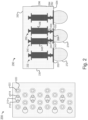
- FIG. 2 schematically illustrates a top view 200 and a cross-section side view 290 of example two-via clustering patterns, in accordance with some embodiments.
- Three-via clustering patterns or ground via clustering patterns with more than three ground vias may also be used in other embodiments.
- a cluster of ground vias instead of a single ground via may be used to mitigate or reduce the crosstalk without the need for any additional interconnect structures between two package substrates.
- the cluster of ground vias may be surrounded by signal vias, of a same layer (e.g., layer 296), in a hexagonal pattern.
- one cluster of ground vias e.g., ground vias 212 and 214
- six signal vias e.g., signal via 222
- other patterns e.g., four signal vias disposed in a square arrangement around a cluster of ground vias, may also be used without departing from the scope of this disclosure.
- the two ground vias may be formed substantially apart from each other, but may still contact the same underlying contact structure (e.g., ball pad).
- ground vias 212 and 214 are formed apart from each other, but still contact the same ball pad 210.
- Cross-section side view 290 schematically illustrates an example two-via clustering pattern.
- Package substrate 230 has one side (e.g., side 282) to receive a die and another side (e.g., side 284) to be coupled with another package substrate or circuit board.
- vertical interconnect structures e.g., vertical interconnect structures 232, 240, and 250
- Vertical interconnect structures may electrically couple structures such as, for example, traces, trenches, vias, lands, pads or other structures that may establish corresponding electrical pathways for electrical signals through package substrate 230.
- vertical interconnect structures may be longer than 1 millimeter (mm), including stacks of micro-vias and core vias, and a solder ball.
- a core via may be an opening through the core substrate filled with conducting material that may be used to connect routing features, e.g., a metal pad, placed on one face of the substrate core with routing features, e.g., another metal pad, placed on the opposite face of the substrate core.
- routing features e.g., a metal pad
- routing features e.g., another metal pad
- a core via may be much bigger than a micro-via as the core layer may be much thicker than build-up layers in an organic package.
- vertical interconnect structure 232 includes stacks of vias disposed on ball pad 262, which in turn has solder ball 272 disposed thereon. Vertical interconnect structure 232 is used to route signals through package substrate 230.
- vertical interconnect structure 240 includes stacks of vias (e.g., via 242, via 244, and via 246) disposed on ball pad 264, which in turn has solder ball 274 disposed thereon.
- Vertical interconnect structure 240 is used to route a ground through package substrate 230.
- vertical interconnect structure 250 includes stacks of vias (e.g., via 252, via 254, and via 256) disposed on a same ball pad 264, which in turn has solder ball 274 disposed thereon.
- Vertical interconnect structure 250 is also used to route a ground through package substrate 230.
- package substrate 230 may be an epoxy-based laminate substrate having build-up layers such as, for example, an Ajinomoto Build-up Film (ABF) substrate.
- package substrate 230 may include other suitable types of substrates including, for example, substrates formed from glass, ceramic, or semiconductor materials.
- via 242 and via 252 are formed in the same substrate layer 292, while via 244 and via 254 are formed in the same substrate layer 294.
- via 246 and via 256 may be formed in the same substrate layer 296.
- via 246 and via 256 may be core vias in a core layer.
- Via 242 and via 252 form a ground via cluster in layer 292
- via 244 and via 254 form another ground via cluster in layer 294.
- via 246 and via 256 may form yet another ground via cluster in layer 296.
- via 242 and via 252 are formed in layer 292 in any conventional manner known in the art.
- an opening may be formed over pad 264 by drilling in a region of dielectric material disposed over pad 264, using a technique, such as employing CO2 or a UV laser.
- any conventional plating operations may be used to deposit electrically conductive material into the openings to form vias.
- electrolytic plating operations may be used to deposit the electrically conductive material into the drilled openings, and chemical, mechanical polishing (CMP) or copper (Cu) etching operations may be used after depositing the electrically conductive material to remove any excess electrically conductive material.
- via 246 and via 256 may be formed in layer 296 with similar or different manners known in the art.
- layer 292, layer 294, or layer 296 are a dielectric layer composed of any of a wide variety of suitable dielectric materials including, for example, epoxy-based laminate material, silicon oxide (SiO2), silicon carbide (SiC), silicon carbonitride (SiCN), or a silicon nitride (e.g., SiN, Si3N4, etc.).
- layer 292 or layer 294 may include a polymer (e.g., epoxy-based resin) and may further include a filler (e.g., silica) to provide suitable mechanical properties to meet reliability standards of the resulting package.
- layer 292, layer 294, or layer 296 may be formed as a film of polymer, such as by ABF lamination.
- layer 292, layer 294, or layer 296 may be formed by depositing a dielectric material using any suitable technique including, for example, atomic layer deposition (ALD), physical vapor deposition (PVD) or chemical vapor deposition (CVD) techniques.
- ALD atomic layer deposition
- PVD physical vapor deposition
- CVD chemical vapor deposition
- substrate 230 includes multiple routing features, such as pad 262 or pad 264, configured to advance the electrical pathways within or through the substrate.
- pad 262 or pad 264 may be composed of any suitable electrically conductive material such as metal including, for example, nickel (Ni), palladium (Pd), gold (Au), silver (Ag), copper (Cu), or any combinations thereof.
- pad 262 or pad 264 may be formed using a patterned metal layer configured to: electrically couple pad 262 with vertical interconnect structure 232 to route electrical signals through the package substrate 230; or electrically couple pad 264 with vertical interconnect structures 240 and 250 to route a ground through the package substrate 230.
- the patterned metal layer may be formed in any conventional manner known in the art.
- the patterned metal layer may be an inner or outermost conductive layer of a build-up layer formed with a semi-additive process (SAP).
- SAP semi-additive process
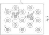
- FIG. 3 schematically illustrates a top view of example three-via clustering patterns, in accordance with some embodiments.
- examples of using three-via clustering may be used in a hexagonal arrangement.
- a cluster of ground vias may be surrounded by signal vias, of the same layer of vias, disposed in a hexagonal pattern, i.e., one cluster of ground vias surrounded by six signal vias.
- the cluster of ground vias 322, 324, and 326 are surrounded by signal vias including signal via 332 in a hexagonal arrangement.
- the cluster of ground vias 352, 354, and 356 may also be surrounded by signal vias in a similar hexagonal arrangement.
- other patterns e.g., four signal vias disposed in a square arrangement around a cluster of ground vias, may also be used to arrange signals vias surrounding the cluster of ground vias without departing from the scope of the present disclosure.
- ground via clustering may be used for the SVLC package substrates and standard core package substrates.
- the SVLC package substrates and the standard core package substrates may have to comport with various different design rules and different ball pitches.
- two ground vias may be successfully added to form the three-via cluster without violating these existing design rules.
- vertical interconnect structure stacks of micro-vias and core-vias may be formed adjacent to original ground vias in an existing design, and, as a result, may maintain the form factor of the design.
- the cluster of ground vias may be in a triangular arrangement.
- ground vias 322, 324, and 326 are depicted in a triangular arrangement.
- ground vias 352, 354, and 356 are depicted in another triangular arrangement.
- one ground via may be disposed over the center of the underlying contact (e.g., a ball pad), and the other two ground vias may be added to a side of the underlying contact.
- via 322 is placed at the center of ball pad 320, in a similar manner to ground via 342 and its associated ball pad.
- ground vias 324 and 326 may be added to ground via 322 to form the ground via cluster in a triangular arrangement.
- the center of the triangular arrangement of ground vias may be disposed over the center of the underlying contact.
- ground vias 352, 354, and 356 form a triangular arrangement, and the center of the cluster overlaps with the center of ball pad 350.
- ground vias may be arranged in various cluster designs.
- the number of ground vias to be clustered may be more than three depending on the design space or other design constraints.
- the ground via cluster may be placed closer to certain signals as an emphasis.
- the arrangement of ground vias 322, 324, and 326 has more emphasis on signals near edge 310 because those signals generally demonstrate greater inclination for crosstalk.
- the ground via cluster may be centered, as shown in the arrangement of ground vias 352, 354, and 356, which may provide an equal improvement on all the surrounding signals.
- ground via clustering as shown in Fig. 3 , may reduce far-end crosstalk (FEXT) and near-end crosstalk (NEXT). Consequently, the signal-to-noise ratio (SNR) may be improved for the channel.
- FEXT far-end crosstalk
- NEXT near-end crosstalk
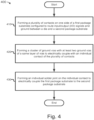
- FIG. 4 schematically illustrates a flow diagram of an example process 400 of forming a ground via cluster for crosstalk mitigation in IC assemblies (e.g., IC assembly 100 of FIG. 1 ), in accordance with some embodiments.
- the process 400 may comport with embodiments described in connection with previous figures according to various embodiments.
- the process 400 may include forming a plurality of electrical contacts on one side of a first package substrate configured to route input/output (I/O) signals and ground between a die and a second package substrate.
- the contacts on the side of the first package substrate may include ball pads.
- ball pads may be solder mask defined (SMD).
- ball pads may be non-solder mask defined (NSMD).
- forming contacts on one side of the package substrate may be realized by embedding the contacts (e.g., pads) in build-up layers (e.g., the outermost build-up layer) as part of the formation of the build-up layers.
- forming contacts on one side of the package substrate may be realized by forming openings in the build-up layers and disposing the contacts (e.g., pads) into the cavities subsequent to formation of the build-up layers, according to any suitable technique.
- the process 400 may include forming a cluster of ground vias with at least two ground vias, of a same layer of vias, to electrically couple with an individual contact of the plurality of contacts.
- Block 420 may be performed during the fabrication process of a package substrate according to various embodiments, e.g., during the fabrication of various layers of package substrate 230, such as layer 292 or layer 294.
- forming the cluster of ground vias may include forming the cluster of ground vias in a column of ground vias closest to an edge of the package substrate, such as the first column of ground vias.
- the first two columns of signals may demonstrate a higher susceptibility to crosstalk than the inner columns; thus, forming the cluster of ground vias in a column of ground vias closest to an edge of the package substrate may mitigate such crosstalk.
- block 420 may be performed only to the column of ground vias closest to the edge, which may yield a cost-effective solution in reducing such crosstalk.
- forming the cluster of ground vias may include forming the cluster of ground vias surrounded by signal vias of the same layer of vias. As illustrated in Fig. 3 , the cluster of ground vias 322, 324, and 326 may be surrounded by signal vias including signal via 332 in a hexagonal arrangement.
- computing device 500 may include other components that may or may not be physically and electrically coupled to motherboard 502. These other components may include, but are not limited to, volatile memory (e.g., DRAM), non-volatile memory (e.g., ROM), flash memory, a graphics processor, a digital signal processor, a crypto processor, a chipset, an antenna, a display, a touchscreen display, a touchscreen controller, a battery, an audio codec, a video codec, a power amplifier, a global positioning system (GPS) device, a compass, a Geiger counter, an accelerometer, a gyroscope, a speaker, a camera, and a mass storage device (such as hard disk drive, compact disk (CD), digital versatile disk (DVD), and so forth).
- volatile memory e.g., DRAM
- non-volatile memory e.g., ROM
- flash memory e.g., a graphics processor, a digital signal processor, a crypto processor, a chipset
- Communication chip 506 may operate in accordance with a Global System for Mobile Communication (GSM), General Packet Radio Service (GPRS), Universal Mobile Telecommunications System (UMTS), High Speed Packet Access (HSPA), Evolved HSPA (E-HSPA), or LTE network.
- GSM Global System for Mobile Communication
- GPRS General Packet Radio Service
- UMTS Universal Mobile Telecommunications System
- High Speed Packet Access HSPA
- E-HSPA Evolved HSPA
- LTE LTE network.
- Communication chip 506 may operate in accordance with Enhanced Data for GSM Evolution (EDGE), GSM EDGE Radio Access Network (GERAN), Universal Terrestrial Radio Access Network (UTRAN), or Evolved UTRAN (E-UTRAN).
- EDGE Enhanced Data for GSM Evolution
- GERAN GSM EDGE Radio Access Network
- UTRAN Universal Terrestrial Radio Access Network
- E-UTRAN Evolved UTRAN
- Communication chip 506 may also include one or more dies that may be packaged in an IC assembly (e.g., IC assembly 100 of FIG. 1 ) that includes a substrate (e.g., package substrate 112 of FIG. 1 ) with vertical interconnect structures having ground via clusters formed according to techniques as described herein.
- IC assembly e.g., IC assembly 100 of FIG. 1
- substrate e.g., package substrate 112 of FIG. 1
- vertical interconnect structures having ground via clusters formed according to techniques as described herein.
Landscapes
- Production Of Multi-Layered Print Wiring Board (AREA)
- Physics & Mathematics (AREA)
- Geometry (AREA)
- Structure Of Printed Boards (AREA)
- Internal Circuitry In Semiconductor Integrated Circuit Devices (AREA)
- Wire Bonding (AREA)
Applications Claiming Priority (5)
| Application Number | Priority Date | Filing Date | Title |
|---|---|---|---|
| US14/575,956 US9230900B1 (en) | 2014-12-18 | 2014-12-18 | Ground via clustering for crosstalk mitigation |
| US14/943,880 US9515017B2 (en) | 2014-12-18 | 2015-11-17 | Ground via clustering for crosstalk mitigation |
| EP21175747.1A EP3951867B1 (en) | 2014-12-18 | 2015-12-03 | Ground via clustering for crosstalk mitigation |
| PCT/US2015/063822 WO2016099936A1 (en) | 2014-12-18 | 2015-12-03 | Ground via clustering for crosstalk mitigation |
| EP15870674.7A EP3234993B1 (en) | 2014-12-18 | 2015-12-03 | Ground via clustering for crosstalk mitigation |
Related Parent Applications (4)
| Application Number | Title | Priority Date | Filing Date |
|---|---|---|---|
| EP15870674.7A Division EP3234993B1 (en) | 2014-12-18 | 2015-12-03 | Ground via clustering for crosstalk mitigation |
| EP21175747.1A Division EP3951867B1 (en) | 2014-12-18 | 2015-12-03 | Ground via clustering for crosstalk mitigation |
| EP21175747.1A Division-Into EP3951867B1 (en) | 2014-12-18 | 2015-12-03 | Ground via clustering for crosstalk mitigation |
| PCT/US2015/063822 Previously-Filed-Application WO2016099936A1 (en) | 2014-12-18 | 2015-12-03 | Ground via clustering for crosstalk mitigation |
Publications (3)
| Publication Number | Publication Date |
|---|---|
| EP4220709A2 EP4220709A2 (en) | 2023-08-02 |
| EP4220709A3 EP4220709A3 (en) | 2023-08-09 |
| EP4220709B1 true EP4220709B1 (en) | 2025-01-29 |
Family
ID=56127342
Family Applications (5)
| Application Number | Title | Priority Date | Filing Date |
|---|---|---|---|
| EP22217374.2A Active EP4220709B1 (en) | 2014-12-18 | 2015-12-03 | Ground via clustering for crosstalk mitigation |
| EP18214233.1A Active EP3483932B1 (en) | 2014-12-18 | 2015-12-03 | Ground via clustering for crosstalk mitigation |
| EP15870674.7A Active EP3234993B1 (en) | 2014-12-18 | 2015-12-03 | Ground via clustering for crosstalk mitigation |
| EP20200804.1A Active EP3799118B1 (en) | 2014-12-18 | 2015-12-03 | Ground via clustering for crosstalk mitigation |
| EP21175747.1A Active EP3951867B1 (en) | 2014-12-18 | 2015-12-03 | Ground via clustering for crosstalk mitigation |
Family Applications After (4)
| Application Number | Title | Priority Date | Filing Date |
|---|---|---|---|
| EP18214233.1A Active EP3483932B1 (en) | 2014-12-18 | 2015-12-03 | Ground via clustering for crosstalk mitigation |
| EP15870674.7A Active EP3234993B1 (en) | 2014-12-18 | 2015-12-03 | Ground via clustering for crosstalk mitigation |
| EP20200804.1A Active EP3799118B1 (en) | 2014-12-18 | 2015-12-03 | Ground via clustering for crosstalk mitigation |
| EP21175747.1A Active EP3951867B1 (en) | 2014-12-18 | 2015-12-03 | Ground via clustering for crosstalk mitigation |
Country Status (7)
| Country | Link |
|---|---|
| US (8) | US9515017B2 (enExample) |
| EP (5) | EP4220709B1 (enExample) |
| JP (1) | JP6789945B2 (enExample) |
| KR (3) | KR102863843B1 (enExample) |
| CN (4) | CN110085567B (enExample) |
| SG (1) | SG11201704038WA (enExample) |
| WO (1) | WO2016099936A1 (enExample) |
Families Citing this family (23)
| Publication number | Priority date | Publication date | Assignee | Title |
|---|---|---|---|---|
| US9515017B2 (en) | 2014-12-18 | 2016-12-06 | Intel Corporation | Ground via clustering for crosstalk mitigation |
| US10068181B1 (en) | 2015-04-27 | 2018-09-04 | Rigetti & Co, Inc. | Microwave integrated quantum circuits with cap wafer and methods for making the same |
| DE112015006975T5 (de) * | 2015-09-25 | 2019-05-09 | Intel Corporation | Mikroelektronische Packung mit drahtloser Zwischenverbindung |
| US11277922B2 (en) | 2016-10-06 | 2022-03-15 | Advanced Micro Devices, Inc. | Circuit board with bridge chiplets |
| US9991215B1 (en) * | 2017-01-19 | 2018-06-05 | Nanya Technology Corporation | Semiconductor structure with through substrate via and manufacturing method thereof |
| US11121301B1 (en) | 2017-06-19 | 2021-09-14 | Rigetti & Co, Inc. | Microwave integrated quantum circuits with cap wafers and their methods of manufacture |
| US10510721B2 (en) | 2017-08-11 | 2019-12-17 | Advanced Micro Devices, Inc. | Molded chip combination |
| US11160163B2 (en) | 2017-11-17 | 2021-10-26 | Texas Instruments Incorporated | Electronic substrate having differential coaxial vias |
| CN111919297B (zh) * | 2018-03-31 | 2025-02-18 | 华为技术有限公司 | 一种半导体封装结构及其封装方法 |
| US10593628B2 (en) | 2018-04-24 | 2020-03-17 | Advanced Micro Devices, Inc. | Molded die last chip combination |
| US10593620B2 (en) | 2018-04-27 | 2020-03-17 | Advanced Micro Devices, Inc. | Fan-out package with multi-layer redistribution layer structure |
| US10672712B2 (en) | 2018-07-30 | 2020-06-02 | Advanced Micro Devices, Inc. | Multi-RDL structure packages and methods of fabricating the same |
| US10373901B1 (en) * | 2018-09-26 | 2019-08-06 | Taiwan Semiconductor Manufacturing Company Ltd. | Semiconductor structure and manufacturing method thereof |
| US11710694B2 (en) * | 2019-05-24 | 2023-07-25 | Intel Corporation | Integrated circuit structures with contoured interconnects |
| US10923430B2 (en) | 2019-06-30 | 2021-02-16 | Advanced Micro Devices, Inc. | High density cross link die with polymer routing layer |
| US11367628B2 (en) | 2019-07-16 | 2022-06-21 | Advanced Micro Devices, Inc. | Molded chip package with anchor structures |
| US11742301B2 (en) | 2019-08-19 | 2023-08-29 | Advanced Micro Devices, Inc. | Fan-out package with reinforcing rivets |
| US11670578B2 (en) * | 2020-06-02 | 2023-06-06 | Micron Technology, Inc. | Ball grid arrays and associated apparatuses and systems |
| CN113192923B (zh) * | 2021-03-30 | 2024-04-19 | 新华三半导体技术有限公司 | 一种封装基板的设计方法、封装基板和芯片 |
| WO2023214654A1 (ko) * | 2022-05-03 | 2023-11-09 | 삼성전자 주식회사 | 인터포져를 포함하는 전자 장치 |
| CN116682800B (zh) * | 2023-06-08 | 2024-02-23 | 合芯科技有限公司 | 一种导体结构、半导体封装结构及电路板 |
| US20250029931A1 (en) * | 2023-07-20 | 2025-01-23 | Cisco Technology, Inc. | Package assembly for integrated circuit |
| TWI893608B (zh) * | 2024-01-11 | 2025-08-11 | 立錡科技股份有限公司 | 半導體封裝結構及其製造方法 |
Family Cites Families (75)
| Publication number | Priority date | Publication date | Assignee | Title |
|---|---|---|---|---|
| US6728113B1 (en) * | 1993-06-24 | 2004-04-27 | Polychip, Inc. | Method and apparatus for non-conductively interconnecting integrated circuits |
| US5841191A (en) | 1997-04-21 | 1998-11-24 | Lsi Logic Corporation | Ball grid array package employing raised metal contact rings |
| US6555417B2 (en) | 2000-12-05 | 2003-04-29 | Analog Devices, Inc. | Method and device for protecting micro electromechanical system structures during dicing of a wafer |
| US6906414B2 (en) * | 2000-12-22 | 2005-06-14 | Broadcom Corporation | Ball grid array package with patterned stiffener layer |
| US20020079572A1 (en) * | 2000-12-22 | 2002-06-27 | Khan Reza-Ur Rahman | Enhanced die-up ball grid array and method for making the same |
| US20040070080A1 (en) * | 2001-02-27 | 2004-04-15 | Chippac, Inc | Low cost, high performance flip chip package structure |
| US6563340B1 (en) * | 2001-05-21 | 2003-05-13 | Cypress Semiconductor Corp. | Architecture for implementing two chips in a package |
| US6525407B1 (en) | 2001-06-29 | 2003-02-25 | Novellus Systems, Inc. | Integrated circuit package |
| JP2004535065A (ja) * | 2001-07-02 | 2004-11-18 | ダウ・コーニング・コーポレイション | 多孔質材料上のSiC:H蒸着によって改良された金属バリア挙動 |
| EP1673807B1 (en) * | 2003-10-10 | 2019-12-11 | Taiwan Semiconductor Manufacturing Co., Ltd. | Electronic Device |
| US7166492B2 (en) * | 2003-11-14 | 2007-01-23 | Lsi Logic Corporation | Integrated circuit carrier apparatus method and system |
| US20050230821A1 (en) * | 2004-04-15 | 2005-10-20 | Kheng Lee T | Semiconductor packages, and methods of forming semiconductor packages |
| US7189594B2 (en) | 2004-09-10 | 2007-03-13 | Agency For Science, Technology And Research | Wafer level packages and methods of fabrication |
| JP4828164B2 (ja) * | 2005-06-06 | 2011-11-30 | ローム株式会社 | インタポーザおよび半導体装置 |
| KR101045505B1 (ko) * | 2005-06-15 | 2011-06-30 | 이비덴 가부시키가이샤 | 다층 프린트 배선판 |
| US7675157B2 (en) * | 2006-01-30 | 2010-03-09 | Marvell World Trade Ltd. | Thermal enhanced package |
| US7473577B2 (en) * | 2006-08-11 | 2009-01-06 | International Business Machines Corporation | Integrated chip carrier with compliant interconnect |
| SG146460A1 (en) * | 2007-03-12 | 2008-10-30 | Micron Technology Inc | Apparatus for packaging semiconductor devices, packaged semiconductor components, methods of manufacturing apparatus for packaging semiconductor devices, and methods of manufacturing semiconductor components |
| US20080284037A1 (en) * | 2007-05-15 | 2008-11-20 | Andry Paul S | Apparatus and Methods for Constructing Semiconductor Chip Packages with Silicon Space Transformer Carriers |
| KR20090118747A (ko) * | 2008-05-14 | 2009-11-18 | 삼성전자주식회사 | 관통 전극을 가지는 반도체 칩 패키지 및 인쇄회로기판 |
| US20100019374A1 (en) * | 2008-07-25 | 2010-01-28 | Stmicroelectronics, Inc. | Ball grid array package |
| JP2010045134A (ja) * | 2008-08-11 | 2010-02-25 | Shinko Electric Ind Co Ltd | 多層配線基板、半導体パッケージ及び製造方法 |
| US8344512B2 (en) * | 2009-08-20 | 2013-01-01 | International Business Machines Corporation | Three-dimensional silicon interposer for low voltage low power systems |
| US8088647B2 (en) | 2009-11-17 | 2012-01-03 | Broadcom Corporation | Bumping free flip chip process |
| US9385095B2 (en) * | 2010-02-26 | 2016-07-05 | Taiwan Semiconductor Manufacturing Company, Ltd. | 3D semiconductor package interposer with die cavity |
| JP5327654B2 (ja) * | 2010-03-18 | 2013-10-30 | マーベル ワールド トレード リミテッド | インタポーザを備える装置および方法 |
| US8866301B2 (en) * | 2010-05-18 | 2014-10-21 | Taiwan Semiconductor Manufacturing Company, Ltd. | Package systems having interposers with interconnection structures |
| US9437561B2 (en) | 2010-09-09 | 2016-09-06 | Advanced Micro Devices, Inc. | Semiconductor chip with redundant thru-silicon-vias |
| US8293578B2 (en) * | 2010-10-26 | 2012-10-23 | International Business Machines Corporation | Hybrid bonding techniques for multi-layer semiconductor stacks |
| US8805132B2 (en) * | 2010-12-08 | 2014-08-12 | International Business Machines Corporation | Integrated circuit package connected to a data transmission medium |
| KR101209980B1 (ko) * | 2010-12-09 | 2012-12-07 | 주식회사 네패스 | 반도체 패키지 및 그 제조 방법 |
| US8975751B2 (en) * | 2011-04-22 | 2015-03-10 | Tessera, Inc. | Vias in porous substrates |
| US8704384B2 (en) | 2012-02-17 | 2014-04-22 | Xilinx, Inc. | Stacked die assembly |
| KR101798571B1 (ko) | 2012-02-16 | 2017-11-16 | 삼성전자주식회사 | 반도체 패키지 |
| JP6337400B2 (ja) * | 2012-04-24 | 2018-06-06 | 須賀 唯知 | チップオンウエハ接合方法及び接合装置並びにチップとウエハとを含む構造体 |
| US9219032B2 (en) * | 2012-07-09 | 2015-12-22 | Qualcomm Incorporated | Integrating through substrate vias from wafer backside layers of integrated circuits |
| US9490190B2 (en) * | 2012-09-21 | 2016-11-08 | Taiwan Semiconductor Manufacturing Company, Ltd. | Thermal dissipation through seal rings in 3DIC structure |
| US8907470B2 (en) * | 2013-02-21 | 2014-12-09 | International Business Machines Corporation | Millimeter wave wafer level chip scale packaging (WLCSP) device and related method |
| JP6088893B2 (ja) * | 2013-04-09 | 2017-03-01 | ルネサスエレクトロニクス株式会社 | 半導体装置及び配線基板 |
| US9679868B2 (en) | 2013-06-19 | 2017-06-13 | Taiwan Semiconductor Manufacturing Company, Ltd. | Ball height control in bonding process |
| US9508701B2 (en) * | 2013-09-27 | 2016-11-29 | Freescale Semiconductor, Inc. | 3D device packaging using through-substrate pillars |
| KR101833154B1 (ko) * | 2013-12-09 | 2018-04-13 | 인텔 코포레이션 | 패키징된 다이용 세라믹 상의 안테나와 컴퓨팅 시스템 및 이의 제조방법 |
| US9515017B2 (en) * | 2014-12-18 | 2016-12-06 | Intel Corporation | Ground via clustering for crosstalk mitigation |
| US9230900B1 (en) * | 2014-12-18 | 2016-01-05 | Intel Corporation | Ground via clustering for crosstalk mitigation |
| KR101640341B1 (ko) * | 2015-02-04 | 2016-07-15 | 앰코 테크놀로지 코리아 주식회사 | 반도체 패키지 |
| US9842800B2 (en) * | 2016-03-28 | 2017-12-12 | Intel Corporation | Forming interconnect structures utilizing subtractive paterning techniques |
| MY192389A (en) * | 2016-07-01 | 2022-08-18 | Intel Corp | Systems, methods, and apparatuses for implementing a pad on solder mask (posm) semiconductor substrate package |
| US10217716B2 (en) * | 2016-09-12 | 2019-02-26 | Mediatek Inc. | Semiconductor package and method for fabricating the same |
| US11640934B2 (en) * | 2018-03-30 | 2023-05-02 | Intel Corporation | Lithographically defined vertical interconnect access (VIA) in dielectric pockets in a package substrate |
| US10818602B2 (en) * | 2018-04-02 | 2020-10-27 | Amkor Technology, Inc. | Embedded ball land substrate, semiconductor package, and manufacturing methods |
| US10672693B2 (en) * | 2018-04-03 | 2020-06-02 | Intel Corporation | Integrated circuit structures in package substrates |
| US10879220B2 (en) * | 2018-06-15 | 2020-12-29 | Taiwan Semiconductor Manufacturing Company, Ltd. | Package-on-package structure and manufacturing method thereof |
| US10431537B1 (en) * | 2018-06-21 | 2019-10-01 | Intel Corporation | Electromigration resistant and profile consistent contact arrays |
| US11424197B2 (en) * | 2018-07-27 | 2022-08-23 | Taiwan Semiconductor Manufacturing Company, Ltd. | Package, package structure with redistributing circuits and antenna elements and method of manufacturing the same |
| US10700021B2 (en) * | 2018-08-31 | 2020-06-30 | Intel Corporation | Coreless organic packages with embedded die and magnetic inductor structures |
| KR102615197B1 (ko) * | 2018-11-23 | 2023-12-18 | 삼성전자주식회사 | 반도체 패키지 |
| US11990449B2 (en) * | 2019-01-14 | 2024-05-21 | Intel Corporation | Dual RDL stacked die package using vertical wire |
| US11227846B2 (en) * | 2019-01-30 | 2022-01-18 | Mediatek Inc. | Semiconductor package having improved thermal interface between semiconductor die and heat spreading structure |
| US12334447B2 (en) * | 2019-06-27 | 2025-06-17 | Intel Corporation | Lithographically defined vertical interconnect access (VIA) for a bridge die first level interconnect (FLI) |
| US10833053B1 (en) * | 2019-07-17 | 2020-11-10 | Taiwan Semiconductor Manufacturing Company, Ltd. | Semiconductor package and method of forming the same |
| US10825789B1 (en) * | 2019-08-26 | 2020-11-03 | Nxp B.V. | Underbump metallization dimension variation with improved reliability |
| US11532531B2 (en) * | 2019-10-29 | 2022-12-20 | Taiwan Semiconductor Manufacturing Company, Ltd. | Semiconductor package |
| MY203413A (en) * | 2019-12-12 | 2024-06-27 | Intel Corp | Interposer for hybrid interconnect geometry |
| US11430764B2 (en) * | 2019-12-20 | 2022-08-30 | Intel Corporation | Overhang bridge interconnect |
| US11450654B2 (en) * | 2019-12-25 | 2022-09-20 | Taiwan Semiconductor Manufacturing Company, Ltd. | Package structure and method of fabricating the same |
| TWI751051B (zh) * | 2020-04-17 | 2021-12-21 | 台灣積體電路製造股份有限公司 | 半導體結構及其製造方法 |
| US11277902B2 (en) * | 2020-05-25 | 2022-03-15 | Arbe Robotics Ltd. | Single layer radio frequency integrated circuit package and related low loss grounded coplanar transmission line |
| US11646255B2 (en) * | 2021-03-18 | 2023-05-09 | Taiwan Semiconductor Manufacturing Company Limited | Chip package structure including a silicon substrate interposer and methods for forming the same |
| US12191281B2 (en) * | 2021-06-16 | 2025-01-07 | Intel Corporation | Multi-chip package with recessed memory |
| US12368127B2 (en) * | 2021-10-29 | 2025-07-22 | Taiwan Semiconductor Manufacturing Company Limited | Semiconductor chip package having underfill material surrounding a fan-out package and contacting a stress buffer structure sidewall |
| US12394696B2 (en) * | 2022-03-23 | 2025-08-19 | Taiwan Semiconductor Manufacturing Company Limited | Package structure including an array of copper pillars and methods of forming the same |
| US20230386988A1 (en) * | 2022-05-31 | 2023-11-30 | Taiwan Semiconductor Manufacturing Company Limited | Semiconductor package with variable pillar height and methods for forming the same |
| US12406936B2 (en) * | 2022-06-01 | 2025-09-02 | Taiwan Semiconductor Manufacturing Company Limited | Semiconductor package with substrate recess and methods for forming the same |
| US12550798B2 (en) * | 2023-02-07 | 2026-02-10 | Taiwan Semiconductor Manufacturing Company Limited | Interposer with built-in wiring for testing an embedded integrated passive device and methods for forming the same |
| US20250022810A1 (en) * | 2023-07-10 | 2025-01-16 | Taiwan Semiconductor Manufacturing Company Limited | Semiconductor package substrate with stress buffer pads and methods for making the same |
-
2015
- 2015-11-17 US US14/943,880 patent/US9515017B2/en active Active
- 2015-12-03 EP EP22217374.2A patent/EP4220709B1/en active Active
- 2015-12-03 JP JP2017530112A patent/JP6789945B2/ja active Active
- 2015-12-03 EP EP18214233.1A patent/EP3483932B1/en active Active
- 2015-12-03 KR KR1020247016680A patent/KR102863843B1/ko active Active
- 2015-12-03 CN CN201811450623.3A patent/CN110085567B/zh active Active
- 2015-12-03 EP EP15870674.7A patent/EP3234993B1/en active Active
- 2015-12-03 CN CN202411720970.9A patent/CN119560478A/zh active Pending
- 2015-12-03 CN CN202411720971.3A patent/CN119560479A/zh active Pending
- 2015-12-03 EP EP20200804.1A patent/EP3799118B1/en active Active
- 2015-12-03 WO PCT/US2015/063822 patent/WO2016099936A1/en not_active Ceased
- 2015-12-03 KR KR1020237003300A patent/KR102669054B1/ko active Active
- 2015-12-03 SG SG11201704038WA patent/SG11201704038WA/en unknown
- 2015-12-03 CN CN201580062829.7A patent/CN107004668B/zh active Active
- 2015-12-03 EP EP21175747.1A patent/EP3951867B1/en active Active
- 2015-12-03 KR KR1020177013475A patent/KR102494739B1/ko active Active
-
2016
- 2016-12-05 US US15/369,659 patent/US10026682B2/en active Active
-
2018
- 2018-07-03 US US16/026,824 patent/US10396022B2/en active Active
-
2019
- 2019-07-11 US US16/509,387 patent/US10854539B2/en active Active
-
2020
- 2020-10-20 US US17/074,820 patent/US11244890B2/en active Active
-
2021
- 2021-12-30 US US17/566,523 patent/US11742275B2/en active Active
-
2022
- 2022-09-29 US US17/956,766 patent/US11901280B2/en active Active
-
2023
- 2023-12-05 US US18/530,006 patent/US12482733B2/en active Active
Also Published As
Similar Documents
| Publication | Publication Date | Title |
|---|---|---|
| US12482733B2 (en) | Ground via clustering for crosstalk mitigation | |
| CN106206539B (zh) | 互连布线配置 | |
| US9119313B2 (en) | Package substrate with high density interconnect design to capture conductive features on embedded die | |
| US9230900B1 (en) | Ground via clustering for crosstalk mitigation |
Legal Events
| Date | Code | Title | Description |
|---|---|---|---|
| PUAI | Public reference made under article 153(3) epc to a published international application that has entered the european phase |
Free format text: ORIGINAL CODE: 0009012 |
|
| STAA | Information on the status of an ep patent application or granted ep patent |
Free format text: STATUS: THE APPLICATION HAS BEEN PUBLISHED |
|
| PUAL | Search report despatched |
Free format text: ORIGINAL CODE: 0009013 |
|
| AC | Divisional application: reference to earlier application |
Ref document number: 3234993 Country of ref document: EP Kind code of ref document: P Ref document number: 3951867 Country of ref document: EP Kind code of ref document: P |
|
| AK | Designated contracting states |
Kind code of ref document: A2 Designated state(s): AL AT BE BG CH CY CZ DE DK EE ES FI FR GB GR HR HU IE IS IT LI LT LU LV MC MK MT NL NO PL PT RO RS SE SI SK SM TR |
|
| AK | Designated contracting states |
Kind code of ref document: A3 Designated state(s): AL AT BE BG CH CY CZ DE DK EE ES FI FR GB GR HR HU IE IS IT LI LT LU LV MC MK MT NL NO PL PT RO RS SE SI SK SM TR |
|
| RIC1 | Information provided on ipc code assigned before grant |
Ipc: H01L 23/498 20060101AFI20230630BHEP |
|
| STAA | Information on the status of an ep patent application or granted ep patent |
Free format text: STATUS: REQUEST FOR EXAMINATION WAS MADE |
|
| 17P | Request for examination filed |
Effective date: 20240130 |
|
| RBV | Designated contracting states (corrected) |
Designated state(s): AL AT BE BG CH CY CZ DE DK EE ES FI FR GB GR HR HU IE IS IT LI LT LU LV MC MK MT NL NO PL PT RO RS SE SI SK SM TR |
|
| STAA | Information on the status of an ep patent application or granted ep patent |
Free format text: STATUS: EXAMINATION IS IN PROGRESS |
|
| 17Q | First examination report despatched |
Effective date: 20240604 |
|
| GRAP | Despatch of communication of intention to grant a patent |
Free format text: ORIGINAL CODE: EPIDOSNIGR1 |
|
| STAA | Information on the status of an ep patent application or granted ep patent |
Free format text: STATUS: GRANT OF PATENT IS INTENDED |
|
| INTG | Intention to grant announced |
Effective date: 20240904 |
|
| GRAS | Grant fee paid |
Free format text: ORIGINAL CODE: EPIDOSNIGR3 |
|
| GRAA | (expected) grant |
Free format text: ORIGINAL CODE: 0009210 |
|
| STAA | Information on the status of an ep patent application or granted ep patent |
Free format text: STATUS: THE PATENT HAS BEEN GRANTED |
|
| AC | Divisional application: reference to earlier application |
Ref document number: 3234993 Country of ref document: EP Kind code of ref document: P Ref document number: 3951867 Country of ref document: EP Kind code of ref document: P |
|
| AK | Designated contracting states |
Kind code of ref document: B1 Designated state(s): AL AT BE BG CH CY CZ DE DK EE ES FI FR GB GR HR HU IE IS IT LI LT LU LV MC MK MT NL NO PL PT RO RS SE SI SK SM TR |
|
| REG | Reference to a national code |
Ref country code: GB Ref legal event code: FG4D |
|
| REG | Reference to a national code |
Ref country code: CH Ref legal event code: EP |
|
| REG | Reference to a national code |
Ref country code: IE Ref legal event code: FG4D |
|
| REG | Reference to a national code |
Ref country code: DE Ref legal event code: R096 Ref document number: 602015090959 Country of ref document: DE |
|
| P01 | Opt-out of the competence of the unified patent court (upc) registered |
Free format text: CASE NUMBER: APP_6509/2025 Effective date: 20250207 |
|
| REG | Reference to a national code |
Ref country code: NL Ref legal event code: FP |
|
| PG25 | Lapsed in a contracting state [announced via postgrant information from national office to epo] |
Ref country code: RS Free format text: LAPSE BECAUSE OF FAILURE TO SUBMIT A TRANSLATION OF THE DESCRIPTION OR TO PAY THE FEE WITHIN THE PRESCRIBED TIME-LIMIT Effective date: 20250429 |
|
| PG25 | Lapsed in a contracting state [announced via postgrant information from national office to epo] |
Ref country code: FI Free format text: LAPSE BECAUSE OF FAILURE TO SUBMIT A TRANSLATION OF THE DESCRIPTION OR TO PAY THE FEE WITHIN THE PRESCRIBED TIME-LIMIT Effective date: 20250129 |
|
| PG25 | Lapsed in a contracting state [announced via postgrant information from national office to epo] |
Ref country code: PL Free format text: LAPSE BECAUSE OF FAILURE TO SUBMIT A TRANSLATION OF THE DESCRIPTION OR TO PAY THE FEE WITHIN THE PRESCRIBED TIME-LIMIT Effective date: 20250129 |
|
| PG25 | Lapsed in a contracting state [announced via postgrant information from national office to epo] |
Ref country code: ES Free format text: LAPSE BECAUSE OF FAILURE TO SUBMIT A TRANSLATION OF THE DESCRIPTION OR TO PAY THE FEE WITHIN THE PRESCRIBED TIME-LIMIT Effective date: 20250129 |
|
| REG | Reference to a national code |
Ref country code: LT Ref legal event code: MG9D |
|
| PG25 | Lapsed in a contracting state [announced via postgrant information from national office to epo] |
Ref country code: IS Free format text: LAPSE BECAUSE OF FAILURE TO SUBMIT A TRANSLATION OF THE DESCRIPTION OR TO PAY THE FEE WITHIN THE PRESCRIBED TIME-LIMIT Effective date: 20250529 Ref country code: NO Free format text: LAPSE BECAUSE OF FAILURE TO SUBMIT A TRANSLATION OF THE DESCRIPTION OR TO PAY THE FEE WITHIN THE PRESCRIBED TIME-LIMIT Effective date: 20250429 |
|
| REG | Reference to a national code |
Ref country code: AT Ref legal event code: MK05 Ref document number: 1764350 Country of ref document: AT Kind code of ref document: T Effective date: 20250129 |
|
| PG25 | Lapsed in a contracting state [announced via postgrant information from national office to epo] |
Ref country code: HR Free format text: LAPSE BECAUSE OF FAILURE TO SUBMIT A TRANSLATION OF THE DESCRIPTION OR TO PAY THE FEE WITHIN THE PRESCRIBED TIME-LIMIT Effective date: 20250129 |
|
| PG25 | Lapsed in a contracting state [announced via postgrant information from national office to epo] |
Ref country code: LV Free format text: LAPSE BECAUSE OF FAILURE TO SUBMIT A TRANSLATION OF THE DESCRIPTION OR TO PAY THE FEE WITHIN THE PRESCRIBED TIME-LIMIT Effective date: 20250129 Ref country code: PT Free format text: LAPSE BECAUSE OF FAILURE TO SUBMIT A TRANSLATION OF THE DESCRIPTION OR TO PAY THE FEE WITHIN THE PRESCRIBED TIME-LIMIT Effective date: 20250529 |
|
| PG25 | Lapsed in a contracting state [announced via postgrant information from national office to epo] |
Ref country code: BG Free format text: LAPSE BECAUSE OF FAILURE TO SUBMIT A TRANSLATION OF THE DESCRIPTION OR TO PAY THE FEE WITHIN THE PRESCRIBED TIME-LIMIT Effective date: 20250129 Ref country code: GR Free format text: LAPSE BECAUSE OF FAILURE TO SUBMIT A TRANSLATION OF THE DESCRIPTION OR TO PAY THE FEE WITHIN THE PRESCRIBED TIME-LIMIT Effective date: 20250430 |
|
| PG25 | Lapsed in a contracting state [announced via postgrant information from national office to epo] |
Ref country code: AT Free format text: LAPSE BECAUSE OF FAILURE TO SUBMIT A TRANSLATION OF THE DESCRIPTION OR TO PAY THE FEE WITHIN THE PRESCRIBED TIME-LIMIT Effective date: 20250129 |
|
| PG25 | Lapsed in a contracting state [announced via postgrant information from national office to epo] |
Ref country code: SE Free format text: LAPSE BECAUSE OF FAILURE TO SUBMIT A TRANSLATION OF THE DESCRIPTION OR TO PAY THE FEE WITHIN THE PRESCRIBED TIME-LIMIT Effective date: 20250129 |
|
| PG25 | Lapsed in a contracting state [announced via postgrant information from national office to epo] |
Ref country code: SM Free format text: LAPSE BECAUSE OF FAILURE TO SUBMIT A TRANSLATION OF THE DESCRIPTION OR TO PAY THE FEE WITHIN THE PRESCRIBED TIME-LIMIT Effective date: 20250129 |
|
| PG25 | Lapsed in a contracting state [announced via postgrant information from national office to epo] |
Ref country code: DK Free format text: LAPSE BECAUSE OF FAILURE TO SUBMIT A TRANSLATION OF THE DESCRIPTION OR TO PAY THE FEE WITHIN THE PRESCRIBED TIME-LIMIT Effective date: 20250129 |
|
| PG25 | Lapsed in a contracting state [announced via postgrant information from national office to epo] |
Ref country code: IT Free format text: LAPSE BECAUSE OF FAILURE TO SUBMIT A TRANSLATION OF THE DESCRIPTION OR TO PAY THE FEE WITHIN THE PRESCRIBED TIME-LIMIT Effective date: 20250129 |
|
| PG25 | Lapsed in a contracting state [announced via postgrant information from national office to epo] |
Ref country code: CZ Free format text: LAPSE BECAUSE OF FAILURE TO SUBMIT A TRANSLATION OF THE DESCRIPTION OR TO PAY THE FEE WITHIN THE PRESCRIBED TIME-LIMIT Effective date: 20250129 Ref country code: EE Free format text: LAPSE BECAUSE OF FAILURE TO SUBMIT A TRANSLATION OF THE DESCRIPTION OR TO PAY THE FEE WITHIN THE PRESCRIBED TIME-LIMIT Effective date: 20250129 |
|
| PG25 | Lapsed in a contracting state [announced via postgrant information from national office to epo] |
Ref country code: RO Free format text: LAPSE BECAUSE OF FAILURE TO SUBMIT A TRANSLATION OF THE DESCRIPTION OR TO PAY THE FEE WITHIN THE PRESCRIBED TIME-LIMIT Effective date: 20250129 |
|
| PG25 | Lapsed in a contracting state [announced via postgrant information from national office to epo] |
Ref country code: SK Free format text: LAPSE BECAUSE OF FAILURE TO SUBMIT A TRANSLATION OF THE DESCRIPTION OR TO PAY THE FEE WITHIN THE PRESCRIBED TIME-LIMIT Effective date: 20250129 |
|
| REG | Reference to a national code |
Ref country code: DE Ref legal event code: R097 Ref document number: 602015090959 Country of ref document: DE |
|
| REG | Reference to a national code |
Ref country code: DE Ref legal event code: R079 Ref document number: 602015090959 Country of ref document: DE Free format text: PREVIOUS MAIN CLASS: H01L0023498000 Ipc: H10W0070620000 |
|
| PLBE | No opposition filed within time limit |
Free format text: ORIGINAL CODE: 0009261 |
|
| STAA | Information on the status of an ep patent application or granted ep patent |
Free format text: STATUS: NO OPPOSITION FILED WITHIN TIME LIMIT |
|
| PGFP | Annual fee paid to national office [announced via postgrant information from national office to epo] |
Ref country code: NL Payment date: 20251126 Year of fee payment: 11 |
|
| 26N | No opposition filed |
Effective date: 20251030 |
|
| PGFP | Annual fee paid to national office [announced via postgrant information from national office to epo] |
Ref country code: DE Payment date: 20251119 Year of fee payment: 11 |
|
| PGFP | Annual fee paid to national office [announced via postgrant information from national office to epo] |
Ref country code: GB Payment date: 20251120 Year of fee payment: 11 |
|
| PGFP | Annual fee paid to national office [announced via postgrant information from national office to epo] |
Ref country code: FR Payment date: 20251124 Year of fee payment: 11 |