EP4219947A2 - Scrollpumpe mit optimierter spiralgeometrie - Google Patents
Scrollpumpe mit optimierter spiralgeometrie Download PDFInfo
- Publication number
- EP4219947A2 EP4219947A2 EP23179568.3A EP23179568A EP4219947A2 EP 4219947 A2 EP4219947 A2 EP 4219947A2 EP 23179568 A EP23179568 A EP 23179568A EP 4219947 A2 EP4219947 A2 EP 4219947A2
- Authority
- EP
- European Patent Office
- Prior art keywords
- wall
- height
- inner end
- outer end
- spiral
- Prior art date
- Legal status (The legal status is an assumption and is not a legal conclusion. Google has not performed a legal analysis and makes no representation as to the accuracy of the status listed.)
- Granted
Links
Images

Classifications
-
- F—MECHANICAL ENGINEERING; LIGHTING; HEATING; WEAPONS; BLASTING
- F04—POSITIVE - DISPLACEMENT MACHINES FOR LIQUIDS; PUMPS FOR LIQUIDS OR ELASTIC FLUIDS
- F04C—ROTARY-PISTON, OR OSCILLATING-PISTON, POSITIVE-DISPLACEMENT MACHINES FOR LIQUIDS; ROTARY-PISTON, OR OSCILLATING-PISTON, POSITIVE-DISPLACEMENT PUMPS
- F04C18/00—Rotary-piston pumps specially adapted for elastic fluids
- F04C18/02—Rotary-piston pumps specially adapted for elastic fluids of arcuate-engagement type, i.e. with circular translatory movement of co-operating members, each member having the same number of teeth or tooth-equivalents
- F04C18/0207—Rotary-piston pumps specially adapted for elastic fluids of arcuate-engagement type, i.e. with circular translatory movement of co-operating members, each member having the same number of teeth or tooth-equivalents both members having co-operating elements in spiral form
- F04C18/0215—Rotary-piston pumps specially adapted for elastic fluids of arcuate-engagement type, i.e. with circular translatory movement of co-operating members, each member having the same number of teeth or tooth-equivalents both members having co-operating elements in spiral form where only one member is moving
-
- F—MECHANICAL ENGINEERING; LIGHTING; HEATING; WEAPONS; BLASTING
- F04—POSITIVE - DISPLACEMENT MACHINES FOR LIQUIDS; PUMPS FOR LIQUIDS OR ELASTIC FLUIDS
- F04C—ROTARY-PISTON, OR OSCILLATING-PISTON, POSITIVE-DISPLACEMENT MACHINES FOR LIQUIDS; ROTARY-PISTON, OR OSCILLATING-PISTON, POSITIVE-DISPLACEMENT PUMPS
- F04C18/00—Rotary-piston pumps specially adapted for elastic fluids
- F04C18/02—Rotary-piston pumps specially adapted for elastic fluids of arcuate-engagement type, i.e. with circular translatory movement of co-operating members, each member having the same number of teeth or tooth-equivalents
- F04C18/0207—Rotary-piston pumps specially adapted for elastic fluids of arcuate-engagement type, i.e. with circular translatory movement of co-operating members, each member having the same number of teeth or tooth-equivalents both members having co-operating elements in spiral form
- F04C18/0246—Details concerning the involute wraps or their base, e.g. geometry
- F04C18/0269—Details concerning the involute wraps
- F04C18/0276—Different wall heights
-
- F—MECHANICAL ENGINEERING; LIGHTING; HEATING; WEAPONS; BLASTING
- F04—POSITIVE - DISPLACEMENT MACHINES FOR LIQUIDS; PUMPS FOR LIQUIDS OR ELASTIC FLUIDS
- F04C—ROTARY-PISTON, OR OSCILLATING-PISTON, POSITIVE-DISPLACEMENT MACHINES FOR LIQUIDS; ROTARY-PISTON, OR OSCILLATING-PISTON, POSITIVE-DISPLACEMENT PUMPS
- F04C25/00—Adaptations of pumps for special use of pumps for elastic fluids
- F04C25/02—Adaptations of pumps for special use of pumps for elastic fluids for producing high vacuum
-
- F—MECHANICAL ENGINEERING; LIGHTING; HEATING; WEAPONS; BLASTING
- F04—POSITIVE - DISPLACEMENT MACHINES FOR LIQUIDS; PUMPS FOR LIQUIDS OR ELASTIC FLUIDS
- F04C—ROTARY-PISTON, OR OSCILLATING-PISTON, POSITIVE-DISPLACEMENT MACHINES FOR LIQUIDS; ROTARY-PISTON, OR OSCILLATING-PISTON, POSITIVE-DISPLACEMENT PUMPS
- F04C27/00—Sealing arrangements in rotary-piston pumps specially adapted for elastic fluids
- F04C27/005—Axial sealings for working fluid
-
- F—MECHANICAL ENGINEERING; LIGHTING; HEATING; WEAPONS; BLASTING
- F04—POSITIVE - DISPLACEMENT MACHINES FOR LIQUIDS; PUMPS FOR LIQUIDS OR ELASTIC FLUIDS
- F04C—ROTARY-PISTON, OR OSCILLATING-PISTON, POSITIVE-DISPLACEMENT MACHINES FOR LIQUIDS; ROTARY-PISTON, OR OSCILLATING-PISTON, POSITIVE-DISPLACEMENT PUMPS
- F04C29/00—Component parts, details or accessories of pumps or pumping installations, not provided for in groups F04C18/00 - F04C28/00
- F04C29/0021—Systems for the equilibration of forces acting on the pump
- F04C29/0028—Internal leakage control
Definitions
- the present invention relates to a scroll pump, in particular a scroll vacuum pump, according to the preamble of claim 1, as the type essentially, for example, from EP 3 153 708 B1 or the EP 3 647 599 B1 has become known.
- a scroll pump is a positive displacement pump that seals against atmospheric pressure and can be used, among other things, as a compressor.
- a scroll vacuum pump can be used to create a vacuum in a recipient connected to the gas inlet.
- Scroll vacuum pumps are also known as scroll vacuum pumps or spiral conveyors.
- the pumping principle on which a scroll pump is based is known in principle from the prior art and is therefore only briefly explained below.
- a pump stage of a scroll pump has two nested or plugged into one another, for example Archimedean spiral cylinders, which are also simply referred to below as spirals.
- Each spiral cylinder consists of at least one equidistant spiral wall with a support plate provided on one end of the spiral wall, wherein the outer turns of the spiral cylinder, for example the two or three outermost turns of the spiral cylinder, can be formed by wall sections that extend one in Circumferentially have a constant distance. Even if these wall sections are not, strictly speaking, spiral sections form, they are nevertheless assigned to the spiral in the context of the present invention and referred to as turns of the same.
- the spiral cylinders are plugged into one another in such a way that they engage with one another without making contact and partially enclose crescent-shaped or crescent-shaped volumes.
- One of the two spirals is immobile or fixed in the pump housing, while the other spiral is moved along with its carrier plate on a circular path via an eccentric drive, which is why this spiral together with its carrier plate is also referred to as an orbiter.
- the movable spiral thus performs a so-called centrally symmetrical oscillation, which is also referred to as "wobbling" or "orbiting".
- a crescent-shaped volume enclosed between the spiral cylinders migrates increasingly inwards during the orbiting of the movable spiral within the spirals, whereby process gas is conveyed by means of the migrating volume from a gas inlet located radially on the outside to a gas outlet located in the middle of the spiral, which due to the decreasing gas volume a compression of the same leads.
- the axial gap between the spiral wall of one spiral cylinder and the carrier plate of the other spiral cylinder should be as small as possible, otherwise the achievable ultimate pressure and the pumping speed will decrease due to backflow effects of process gas via the axial gap, whereas the required one will decrease Drive power increases in an undesirable manner.
- the size of the axial gaps in question depends on permissible component tolerances, any bearing play, the tilting of the orbiter and the thermal expansion of the spiral cylinder.
- the axial gaps are usually set to a constant size over the entire length of the respective spiral cylinder between its radially inner end and its radially outer end, where the thermal expansion of the respective spiral cylinder can optionally be compensated for by a seal at the free end of the respective spiral wall.
- the heat generated by the operation of the pump can only be dissipated insufficiently, which can lead to a temperature gradient between its radially outer end and its radially inner, especially in the movable spiral cylinder end sets.
- the moveable scroll cylinder as a whole can heat up more than the fixed scroll cylinder. Due to the temperature gradient that occurs, the respective spiral cylinder or its spiral wall can expand to different extents between its radially inner and its radially outer end, so that the respective axial gap in the stationary operating state of the pump exceeds a permissible dimension in some areas and exceeds a permissible dimension in other areas can fall below. Accordingly, the process gas can flow back through the axial gap in the direction of the suction side in areas in which the axial gap exceeds a permissible level, which has a negative effect on the achievable ultimate pressure and the pumping speed of the pump.
- the invention is therefore based on the object of minimizing temperature-related backflow losses of a scroll pump.
- these height specifications refer to the cold condition of the pump or to the nominal heights of the spiral walls with which they are manufactured.
- the first wall height is measured from the first surface of the first support plate, from which the first wall protrudes, to the free end or to the wall head of the first wall.
- the second wall height is measured from the second surface of the second carrier plate, from which the second wall protrudes, to the free end or to the wall head of the second wall.
- any temperature gradients that can occur during operation of the scroll pump along the wall of the respective spiral cylinder are compensated for by wall heights of different heights.
- the respective spiral wall has a lower wall height in areas in which it is warmer than in other areas. Because of the temperature, warmer sections of the respective spiral wall can thus expand more than less warm sections, so that in the stationary operating state of the scroll pump a substantially constant axial gap is established over the entire length of the respective spiral wall. In the stationary operating state of the scroll pump, the axial gap can thus tend to reach its desired nominal size everywhere, so that there are no areas in which undesirably high backflow losses can occur due to the axial gap.
- the first wall height is less at the inner end of the first spiral wall than at the outer end of the first spiral wall.
- it can be provided in a corresponding manner that the second wall height is less at the inner end of the second spiral wall than at the outer end of the second spiral wall.
- the second wall height, ie that of the movable spiral cylinder, at the outer end of the second wall is less than the first wall height at the outer end of the first wall.
- the second wall height at the inner end of the second wall is less than the first wall height at the inner end of the first wall.
- the second spiral wall as a whole can have a lower wall height than the first spiral wall.
- the spiral wall of the movable spiral cylinder can therefore be made somewhat less high in its entirety than the spiral wall of the fixed spiral cylinder.
- axial gaps of essentially the same size can be established at the free end of the movable spiral cylinder and the fixed spiral cylinder.
- the first wall height decreases continuously or steadily, starting from the outer end of the first wall to the inner end of the first wall, without any jumps between the inner end of the first wall and the outer end of the first wall are present at the wall height.
- the second wall height can decrease continuously starting from the outer end of the second wall to the inner end of the second wall, so that there are no jumps in the wall height here either. If you look at the development of the spiral wall, its shape corresponds to that of a trapezium.
- the first wall between its outer end and its inner end has at least one first wall section with a constant first wall height and at least one second wall section with a constant first wall height, which differs from the constant first wall height of the first wall section of the first wall.
- the second wall also comprises at least one first wall section with a constant second wall height and at least one second section with a constant second wall height between its outer end and its inner end, which differs from the constant first wall height of the first wall section of the second wall differs.
- the wall height of the first and/or the second wall changes abruptly or stepwise between the individual wall sections.
- the wall height of the first and/or the second wall changes continuously or constantly between the individual wall sections, so that ramp-like additional wall sections can be provided between the individual wall sections, for example, which connect the wall sections of different heights in a ramp-like manner connect.
- the maximum height difference of the respective wall can be of the order of about 0.05 mm.
- the maximum height difference of the first and/or the second wall height can be 0.05 to 0.5%, preferably 0.1 to 0.3% and particularly preferably 0.15 to 0.25% of the maximum first or second wall height amount in order to be able to compensate for the different temperature expansion behavior of the respective spiral wall over its length.
- the first wall height and/or the second wall height changes between its inner end and its outer end in order to ensure that the respective axial gap in the stationary operating state of the scroll pump reaches its desired nominal size everywhere can.
- the first or second wall can thus expand in the axial direction due to the temperature, without contact occurring with the respective axially adjacent carrier plate. Rather, an axial gap can be established in the stationary operating state, which has the desired nominal dimension everywhere. In this case, it is not necessary for the first wall height and/or the second wall height to change between its inner end and its outer end; Rather, it can be provided in this embodiment that the first wall height and/or the second wall height is constant between its inner end and its outer end.
- the first surface comprises a plurality of first annular surfaces which are concentric to one another and between which there are respective first jumps in depth
- the second surface comprises a plurality of second annular surfaces located concentrically to one another, between which there are respective second jumps in depth.
- the number of wall sections of the first wall corresponds to the number of second annular surfaces, whereby it can be provided in particular that the second depth jumps are located in the radial direction approximately where the wall height of the first wall changes suddenly, and/or that the number of wall sections of the second wall corresponds to the number of first annular surfaces, it being possible in particular for the first depth jumps to be located in the radial direction roughly where the wall height of the second wall suddenly changes changes.
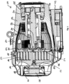
- the 1 shows a vacuum pump designed as a scroll pump 10 .
- This comprises a first housing element 12 and a second housing element 14 connected to it via screws 15, which forms a support plate for a pump-active structure, namely a stationary spiral wall 16.
- the second housing element 14 thus forms a stationary spiral component of the scroll vacuum pump 10.
- the spiral wall 16 cooperates with a movable spiral wall 18, which according to the perspective view of 2 extends circumferentially between an inner end 58 and an outer end 60 . equivalent applies to the fixed scroll wall 16 which also extends between an inner end and an outer end.
- the movable spiral wall 18 is formed on a movable support plate 20 and forms together with this in the 2 Orbiter 21 of the scroll vacuum pump 10 shown in a perspective view, which is driven eccentrically via an eccentric shaft 22 to generate a pumping effect.
- a process gas to be pumped is conveyed from an inlet 24, which is defined in the first housing element 12, to an outlet 26, which is defined in the second housing element 14.
- the eccentric shaft 22 is driven by an electric motor 28 and supported by two roller bearings 30 .
- the eccentric shaft 22 comprises an eccentric pin 32 which is arranged eccentrically to its axis of rotation and which transmits its eccentric deflection to the movable spiral component 20 via a further roller bearing 34 .
- a corrugated bellows 36 On the movable support plate 20, to seal the drive, there is also an in 1 left-hand first end of a corrugated bellows 36 is attached, the right-hand second end of which is attached to the housing base of the first housing element 12 .
- the first end of the corrugated bellows 36 on the left follows the deflection of the movable carrier plate 20.
- the corrugated bellows 36 surrounding the eccentric shaft 22 is flexible but inherently torsionally rigid and thus prevents, due to the fact that it is attached to the carrier plate 20 on the one hand and to the first housing element on the other 12 is fixed so that the carrier plate 20 or the orbiter 21 can rotate about itself.
- the scroll vacuum pump 10 also includes a fan 38 for generating a cooling air flow 46.
- An air guide hood 40 is provided for this cooling air flow 46, to which the fan 38 is also attached.
- the shroud 40 and housing elements 12 and 14 are shaped in such a way that the cooling air flow 46 essentially flows around the entire pump housing and thus achieves good cooling performance.
- the scroll vacuum pump 10 also includes an electronics housing 42 in which a control device and power electronics components for driving the motor 28 are arranged.
- the electronics housing 42 also forms a base for the pump 10.
- a channel 44 is formed between the electronics housing 42 and the first housing element 12, through which the air flow 46 generated by the fan 38 is guided along the first housing element 12 and also along the electronics housing 42, so that both are effective be cooled.
- the movable spiral wall 18, which is also referred to here as the second wall 18, is formed integrally with the carrier plate 20, which forms a flat second surface 19 (see Fig.
- the wall height of the second wall 18 is measured by the flat second surface 19 of the second support plate 20 to the free end or wall head 50 of the second spiral wall 18.
- the fixed spiral wall 16, which is also referred to herein as the first wall 16 is integral with that formed by the second housing element 14 Support plate 14 is formed, the height of the first wall 16 being measured from the flat first surface 17 of this support plate 14 to the free end or to the wall head 52 of the first wall 16 .
- an axial gap 54 which should be as small as possible over the entire developed length of the first spiral wall 16 during pump operation.
- an axial gap 56 is located between the free end 50 of the second spiral wall 18 and the support plate 14 through the second Housing element 14 , which should also be as small as possible.
- the wall height H of the movable spiral wall 18 and/or that of the fixed spiral wall 18 changes between its inner end 58 and its outer end 60.
- the respective spiral wall 16, 18 has a lower wall height in areas of higher temperature than in areas of colder temperature.
- the respective spiral wall 16, 18 can expand more in areas of higher temperature to achieve the smallest possible axial gap 54, 56 than in colder areas.
- the invention provides in particular that the height of the respective wall 16, 18 at the inner end 58 of the respective wall 16 , 18 is slightly less than at the outer end 60 of the respective wall 16, 18. Since the movable scroll wall 18 tends to heat up more than the fixed wall 16 during pumping operation, it can also be provided that the movable wall 18 in its entirety has a lower height than the fixed spiral wall 16, so that the movable spiral wall 18 can expand slightly more than the fixed spiral wall 16 due to temperature. In particular, it can be provided that the movable spiral wall 18 both at its inner end 58 and at its outer end 60 has a smaller wall height H than the fixed scroll wall 16 at the respective ends 58,60.
- the wall height H of the fixed spiral wall 16 or that of the movable spiral wall 18 continuously decreases from the respective outer end 60 to the inner end 58 of the respective spiral wall 16, 18.
- the respective spiral wall 16, 18 has three wall sections 62, 64, 66, each with a different constant wall height H, with the wall height H gradually decreasing in the direction of the inner end 58 of the respective spiral wall 16, 18.
- the wall height H between the individual wall sections 62, 64, 66 changes continuously, so that the individual wall sections 62, 64, 66 are connected to one another via ramp sections 68 with a variable wall height H.
- the wall height H of the respective wall section is lower the closer the respective wall section 62 is , 64, 66 at the inner end 58 of the respective scroll wall 16,18.
- the wall height H in FIGS Figures 3 and 4 exaggerated.
- the maximum height difference of the respective spiral wall 16, 18 only be around 0.05 mm, which would not be visible to the naked eye with a spiral wall height H of the order of 10 to 50 mm.
- the maximum height difference of the respective spiral wall can also be slightly larger, depending on the pump type; in principle, however, the maximum height difference is about 0.05 to 0.5%, preferably 0.1 to 0.3%, and particularly preferably 0.15 to 0.25% of the maximum height dimension of the respective spiral wall 16, 18.
- first surface 17 of the first support plate 14 forms a first cavity or indentation 70 with a variable first depth T1, which increases in the radial direction towards the center of the first support plate 14, and / or that the second Surface 19 of the second carrier plate 20 forms a second cavity or indentation 72 with a variable second depth T2, which increases in the radial direction towards the center of the second carrier plate 20, as is shown in FIGS Figures 3 and 4 is indicated by a bold line L, which only illustrates the first and second surface 17, 19 of the respective support plates 14, 20.
- the first or second depth T1, T2 increases continuously towards the center of the respective carrier plate 14, 20, whereas the increase in depth according to FIG 4 takes place gradually in two steps, which means that the first or second surface 17, 19 is formed by a plurality of first annular surfaces 74 which are concentric to one another and are separated from one another by respective first jumps in depth.
- the number of wall sections 62, 64, 66 of the first wall 16 corresponds to the number of second annular surfaces 74, with the second depth jumps in the radial direction being located at least approximately where the wall height H of the first wall 16 changes suddenly.
- the number of wall sections 62, 64, 66 of the second wall 18 can correspond to the number of first annular surfaces 74, with the first jumps in depth are also located at least approximately in the radial direction where the wall height H of the second wall 18 changes suddenly.
Landscapes
- Engineering & Computer Science (AREA)
- Mechanical Engineering (AREA)
- General Engineering & Computer Science (AREA)
- Rotary Pumps (AREA)
Abstract
Description
- Die vorliegende Erfindung betrifft eine Scrollpumpe, insbesondere Scrollvakuumpumpe, gemäß dem Oberbegriff des Anspruchs 1, wie sie der Art nach im Wesentlichen beispielsweise aus der
EP 3 153 708 B1 oder derEP 3 647 599 B1 bekannt geworden ist. - Eine Scrollpumpe ist eine gegen Atmosphärendruck abdichtende Verdrängerpumpe, die sich unter anderem als Kompressor einsetzen lässt. Eine Scrollvakuumpumpe kann zur Erzeugung eines Vakuums in einem an dem Gaseinlass angeschlossenen Rezipienten verwendet werden.
- Scrollvakuumpumpen werden auch als Spiralvakuumpumpen oder Spiralfördereinrichtungen bezeichnet. Das einer Scrollpumpe zugrundeliegende Pumpprinzip ist aus dem Stand der Technik grundsätzlich bekannt und wird daher nachfolgend nur kursorisch erläutert.
- Eine Pumpstufe einer Scrollpumpe weist zwei ineinander verschachtelte bzw. ineinander gesteckte, beispielsweise archimedische Spiralzylinder auf, welche nachfolgend auch lediglich als Spiralen bezeichnet werden. Jeder Spiralzylinder besteht dabei aus zumindest einer äquidistanten Spiralwand mit einer an einer Stirnseite der Spiralwand vorgesehenen Trägerplatte, wobei die äußeren Windungen des Spiralzylinders, beispielsweise die zwei oder drei äußersten Windungen des Spiralzylinders, durch Wandabschnitte gebildet werden können, die vom Mittelpunkt der Spiralen jeweils einen in Umfangsrichtung konstanten Abstand aufweisen. Auch wenn diese Wandabschnitte somit streng genommen keine Spiralabschnitte bilden, werden sie im Kontext der vorliegenden Erfindung dennoch der Spirale zugerechnet und als Windungen derselben bezeichnet.
- Die Spiralzylinder sind dabei so ineinandergesteckt, dass sie berührungslos miteinander in Eingriff stehen und abschnittsweise halbmond- bzw. sichelförmige Volumina umschließen. Eine der beiden Spiralen ist dabei unbeweglich bzw. feststehend im Gehäuse der Pumpe angeordnet, wohingegen die andere Spirale mitsamt ihrer Trägerplatte über einen Exzenterantrieb auf einer kreisförmigen Bahn bewegt wird, weshalb diese Spirale zusammen mit ihrer Trägerplatte auch als Orbiter bezeichnet wird. Die bewegliche Spirale führt somit eine sogenannte zentralsymmetrische Oszillation aus, was auch als "Wobbeln" oder "Orbitieren" bezeichnet wird. Ein zwischen den Spiralzylindern eingeschlossenes halbmondförmiges Volumen wandert während des Orbitierens der beweglichen Spirale innerhalb der Spiralen zunehmend nach innen, wodurch mittels des wandernden Volumens Prozessgas von einem radial außenliegenden Gaseinlass zu einem in der Spiralmitte befindlichen Gasauslass gefördert wird, was aufgrund des sich dabei verkleinernden Gasvolumens zu einer Komprimierung desselben führt.
- Um eine möglichst hohe Performance der Scrollpumpe zu erreichen, sollte dabei der Axialspalt zwischen der Spiralwand des einen Spiralzylinders und der Trägerplatte des anderen Spiralzylinders möglichst klein sein, da andernfalls durch Rückströmeffekte von Prozessgas über den Axialspalt der erreichbare Enddruck sowie das Saugvermögen abnehmen, wohingegen die erforderliche Antriebsleistung in unerwünschter Weise zunimmt.
- Grundsätzlich hängt die Größe der in Rede stehenden Axialspalte von zulässigen Bauteiltoleranzen, etwaigem Lagerspiel, der Verkippung des Orbiters sowie der Wärmeausdehnung der Spiralzylinder ab. Üblicherweise werden die Axialspalte dabei über die gesamte Länge des jeweiligen Spiralzylinders zwischen seinem radial inneren Ende und seinem radial äußeren Ende auf ein konstantes Maß eingestellt, wobei die thermische Ausdehnung des jeweiligen Spiralzylinders gegebenenfalls durch eine Dichtung am freien Ende der jeweiligen Spiralwand ausgeglichen werden kann.
- Insbesondere dann, wenn jedoch die Pumpe ihren Enddruck erreicht hat, kann allerdings die durch den Betrieb der Pumpe erzeugte Wärme nur unzureichend abgeleitet werden, was dazu führen kann, dass sich insbesondere in dem beweglichen Spiralzylinder ein Temperaturgradient zwischen seinem radial äußeren Ende und seinem radial inneren Ende einstellt. Gleichermaßen kann sich der bewegliche Spiralzylinder in seiner Gesamtheit stärker als der feststehende Spiralzylinder erwärmen. Aufgrund des sich einstellenden Temperaturgradienten kann sich der jeweiligen Spiralzylinder bzw. dessen Spiralwand zwischen seinem radial inneren und seinem radial äußeren Ende unterschiedlich stark ausdehnen, so dass der jeweilige Axialspalt im stationären Betriebszustand der Pumpe bereichsweise ein zulässiges Maß über- und in anderen Bereichen ein zulässiges Maß unterschreiten kann. Dementsprechend kann das Prozessgas in Bereichen, in denen der Axialspalt ein zulässiges Maß überschreitet, durch den Axialspalt in Richtung der Saugseite zurückströmen, was sich negativ auf den erreichbaren Enddruck sowie das Saugvermögen der Pumpe auswirkt.
- Der Erfindung liegt daher die Aufgabe zugrunde, temperaturbedingte Rückströmverluste einer Scrollpumpe zu minimieren.
- Diese Aufgabe wird mit einer Scrollpumpe, insbesondere mit einer Scrollvakuumpumpe, mit den Merkmalen des Anspruchs 1 und insbesondere dadurch gelöst, dass die erste Wandhöhe und/oder die zweite Wandhöhe zwischen ihrem radial inneren Ende und ihrem radial äußeren Ende nicht konstant ist bzw. sich ändert.
- Sofern hier die Wandhöhen der Spiralzylinder einer Scrollpumpe spezifiziert werden, so beziehen sich diese Höhenangaben auf den kalten Zustand der Pumpe bzw. auf die Nennhöhen der Spiralwände, mit denen diese gefertigt werden.
- Die erste Wandhöhe misst sich dabei von der ersten Oberfläche der ersten Trägerplatte, von der die erste Wand absteht, bis zum freien Ende bzw. bis zum Wandkopf der ersten Wand. In entsprechender Weise misst sich die zweite Wandhöhe von der zweiten Oberfläche der zweiten Trägerplatte, von der die zweite Wand absteht, bis zum freien Ende bzw. zum Wandkopf der zweiten Wand.
- Erfindungsgemäß ist es somit vorgesehen, dass sich etwaige Temperaturgradienten, die während des Betriebs der Scrollpumpe entlang der Wand des jeweiligen Spiralzylinders einstellen können, durch unterschiedlich hohe Wandhöhen ausgeglichen werden. Insbesondere ist es hierzu vorgesehen, dass die jeweilige Spiralwand in Bereichen, in denen sie wärmer ist als in anderen Bereichen, eine geringere Wandhöhe aufweist. Wärmere Abschnitte der jeweiligen Spiralwand können sich somit temperaturbedingt stärker als weniger warme Abschnitte ausdehnen, so dass sich im stationären Betriebszustand der Scrollpumpe über die gesamte Länge der jeweiligen Spiralwand hinweg ein im Wesentlichen konstanter Axialspalt einstellt. Im stationären Betriebszustand der Scrollpumpe kann der Axialspalt somit tendenziell überall sein gewünschtes Nennmaß erreichen, so dass keine Bereiche entstehen, in denen durch den Axialspalt unerwünscht hohe Rückströmverluste auftreten können.
- Im Folgenden wird nun auf bevorzugte Ausführungsformen der Erfindung eingegangen. Weitere Ausführungsformen können sich auch aus den abhängigen Ansprüchen, der Figurenbeschreibung sowie den Zeichnungen selbst ergeben.
- So kann es gemäß einer Ausführungsform vorgesehen sein, dass die erste Wandhöhe am inneren Ende der ersten Spiralwand geringer ist als am äußeren Ende der ersten Spiralwand. Zusätzlich oder alternativ hierzu kann es in entsprechender Weise vorgesehen sein, dass die zweite Wandhöhe am inneren Ende der zweiten Spiralwand geringer ist als am äußeren Ende der zweiten Spiralwand.
- So wurde nämlich erfindungsgemäß erkannt, dass sich während des Pumpbetriebs der Scrollpumpe in dem jeweiligen Spiralzylinder tendenziell ein Temperaturgradient einstellt, der in Richtung des inneren Endes der jeweiligen Spiralwand zunimmt. Um diese Temperaturzunahme in Richtung des inneren Endes der jeweiligen Spiralwand ausgleichen zu können, kann es daher erfindungsgemäß vorgesehen sein, dass die jeweilige Spiralwandhöhe am inneren Ende der jeweiligen Spiralwand tendenziell geringer ist als am äußeren Ende der jeweiligen Spiralwand.
- Bei einem Spiralzylinder konstanter Wandhöhe würde sich hingegen im stationären Betriebszustand am radial äußeren Ende ein Axialspalt einstellen, der größer als am inneren Ende des Spiralzylinders ist, so dass am radial äußeren Ende durch den Axialspalt in unerwünschter Weise Prozessgas zurück in Richtung des Pumpeneinlasses strömen könnte. Dadurch, dass erfindungsgemäß die Spiralwandhöhe im kalten Zustand der Pumpe zum radial äußeren Ende der jeweiligen Spiralwand hin zunimmt, wird die mangelnde Wärmeausdehnung am radial äußeren Ende gewissermaßen vorweggenommen, so dass sich auch am radial äußeren Ende der Spiralwand im stationären Betriebszustand ein Axialspalt mit der gewünschten Größe einstellt.
- Gemäß einer weiteren Ausführungsform kann es vorgesehen sein, dass die zweite Wandhöhe, also die des beweglichen Spiralzylinders, am äußeren Ende der zweiten Wand geringer ist als die erste Wandhöhe am äußeren Ende der ersten Wand. Zusätzlich oder alternativ hierzu kann es vorgesehen sein, dass die zweite Wandhöhe am inneren Ende der zweiten Wand geringer ist als die erste Wandhöhe am inneren Ende der ersten Wand. Anders ausgedrückt, kann also die zweite Spiralwand in ihrer Gesamtheit eine geringere Wandhöhe aufweisen als die erste Spiralwand. So wurde nämlich erfindungsgemäß erkannt, dass die Wärme aus dem feststehenden Spiralzylinder aufgrund des Kontakts zum Gehäuse der Scrollpumpe tendenziell besser abgeleitet werden kann als die Wärme aus dem beweglichen Spiralzylinder. Damit sich dennoch gleich große Axialspalte einstellen können, kann daher die Spiralwand des beweglichen Spiralzylinders in ihrer Gesamtheit etwas weniger hoch ausgebildet werden als die Spiralwand des feststehenden Spiralzylinders. Somit können sich im stationären Pumpbetrieb am freien Ende des beweglichen Spiralzylinders und des feststehenden Spiralzylinders im Wesentlichen gleich große Axialspalte einstellen.
- Gemäß einer weiteren Ausführungsform kann es vorgesehen sein, dass die erste Wandhöhe ausgehend vom äußeren Ende der ersten Wand bis zum inneren Ende der ersten Wand kontinuierlich bzw. stetig abnimmt, ohne dass zwischen dem inneren Ende der ersten Wand und äußeren Ende der ersten Wand etwaige Sprünge in der Wandhöhe vorhanden sind. Zusätzlich oder alternativ hierzu kann die zweite Wandhöhe ausgehend vom äußeren Ende der zweiten Wand bis zum inneren Ende der zweiten Wand kontinuierlich abnehmen, so dass auch hier keine Sprünge in der Wandhöhe vorliegen. Betrachtet man die Abwicklung der Spiralwand, so entspricht deren Gestalt also der eines Trapez.
- Alternativ zu der zuvor beschriebenen Ausführungsform, bei der die jeweilige Spiralwand der Gestalt eines Trapez entspricht, kann es gemäß einer weiteren Ausführungsform vorgesehen sein, dass die erste Wand zwischen ihrem äußeren Ende und ihrem inneren Ende zumindest einen ersten Wandabschnitt mit konstanter erster Wandhöhe und zumindest einen zweiten Wandabschnitt mit konstanter erster Wandhöhe umfasst, die sich von der konstanten ersten Wandhöhe des ersten Wandabschnitts der ersten Wand unterscheidet. Zusätzlich oder alternativ hierzu kann es vorgesehen sein, dass auch die zweite Wand zwischen ihrem äußeren Ende und ihrem inneren Ende zumindest einen ersten Wandabschnitt mit konstanter zweiter Wandhöhe und zumindest einen zweiten Abschnitt mit konstanter zweiter Wandhöhe umfasst, die sich von der konstanten ersten Wandhöhe des ersten Wandabschnitts der zweiten Wand unterscheidet. Hierbei kann es beispielsweise vorgesehen sein, dass sich die Wandhöhe der ersten und/oder der zweiten Wand zwischen den einzelnen Wandabschnitten sprunghaft bzw. stufenweise verändert. Alternativ hierzu kann es vorgesehen sein, dass sich die Wandhöhe der ersten und/oder der zweiten Wand zwischen den einzelnen Wandabschnitten kontinuierlich bzw. stetig verändert, so dass beispielsweise zwischen den einzelnen Wandabschnitten rampenartige zusätzliche Wandabschnitte vorgesehen sein können, die die unterschiedlich hohen Wandabschnitte rampenartig miteinander verbinden.
- Betrachtet man beispielsweise eine Spiralwand mit einer maximalen Wandhöhe von 50 mm, so kann die maximale Höhendifferenz der jeweiligen Wand in der Größenordnung von etwa 0,05 mm liegen. Ganz allgemein kann die maximale Höhendifferenz der ersten und/oder der zweiten Wandhöhe 0,05 bis 0,5%, vorzugsweise 0,1 bis 0,3% und insbesondere vorzugsweise 0,15 bis 0,25% der maximalen ersten bzw. zweiten Wandhöhe betragen, um so das unterschiedliche Temperaturausdehnungsverhalten der jeweiligen Spiralwand über ihre Länge hinweg kompensieren zu können.
- Bei den zuvor beschriebenen Ausführungsformen ist es vorgesehen, dass sich die erste Wandhöhe und/oder die zweite Wandhöhe zwischen ihrem inneren Ende und ihrem äußeren Ende ändert, um so dafür zu sorgen, dass der jeweilige Axialspalt im stationären Betriebszustand der Scrollpumpe überall sein gewünschtes Nennmaß erreichen kann. Zusätzlich oder alternativ hierzu kann es gemäß einer weiteren Ausführungsform zur Erreichung des gewünschten Nennmaßes des jeweiligen Axialspalts vorgesehen sein, dass die erste Oberfläche der ersten Trägerplatte eine erste Kavität bzw. Eintiefung mit einer ersten Tiefe ausbildet, die in radialer Richtung zur Mitte hin zunimmt, und/oder dass die zweite Oberfläche der zweiten Trägerplatte eine zweite Kavität bzw. Eintiefung mit einer zweiten Tiefe ausbildet, die in radialer Richtung zur Mitte hin zunimmt, und zwar entweder kontinuierlich oder stufenweise. Die erste bzw. zweite Wand kann sich somit temperaturbedingt in axialer Richtung ausdehnen, ohne dass es zu einem Kontakt mit der jeweils axial benachbarten Trägerplatte kommt. Vielmehr kann sich so im stationären Betriebszustand ein Axialspalt einstellen, der überall das gewünschte Nennmaß aufweist. Hierbei ist es nicht erforderlich, dass sich die die erste Wandhöhe und/oder die zweite Wandhöhe zwischen ihrem inneren Ende und ihrem äußeren Ende ändert; vielmehr kann es bei dieser Ausführung vorgesehen sein, dass erste Wandhöhe und/oder die zweite Wandhöhe zwischen ihrem inneren Ende und ihrem äußeren Ende konstant ist.
- Im Falle, dass die Tiefe der jeweiligen Eintiefung in radialer Richtung stufenweise zunimmt, kann es gemäß einer weiteren Ausführungsform vorgesehen sein, dass die erste Oberfläche mehrere konzentrisch zueinander gelegene erste Kreisringflächen umfasst, zwischen denen jeweilige erste Tiefensprünge vorliegen, und/oder dass die zweite Oberfläche mehrere konzentrisch zueinander gelegene zweite Kreisringflächen umfasst, zwischen denen jeweilige zweite Tiefensprünge vorliegen.
- Gemäß einer weiteren Ausführungsform kann es darüber hinaus vorgesehen sein, dass die Anzahl der Wandabschnitte der ersten Wand der Anzahl an zweiten Kreisringflächen entspricht, wobei es insbesondere vorgesehen sein kann, dass sich die zweiten Tiefensprünge in radialer Richtung etwa dort befinden, wo sich die Wandhöhe der ersten Wand sprunghaft verändert, und/oder dass die Anzahl der Wandabschnitte der zweiten Wand der Anzahl an ersten Kreisringflächen entspricht, wobei es insbesondere vorgesehen sein kann, dass sich die ersten Tiefensprünge in radialer Richtung etwa dort befinden, wo sich die Wandhöhe der zweiten Wand sprunghaft ändert.
- Im Folgenden wird die Erfindung nun rein exemplarisch unter Bezugnahme auf die Zeichnungen beschrieben, in denen:
- Fig. 1
- eine herkömmliche Scrollvakuumpumpe in einer Schnittdarstellung zeigt;
- Fig. 2
- eine perspektive Darstellung des Orbiters der Scrollvakuumpumpe der
Fig. 1 zeigt; und - Fig. 3
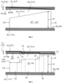
- eine Ausführungsform einer Spiralwand in abgewickelter Darstellung zeigt, wobei die Wandhöhe überhöht dargestellt ist; und
- Fig. 4
- eine weitere Ausführungsform einer Spiralwand in abgewickelter Darstellung zeigt, wobei die Wandhöhe überhöht dargestellt ist.
- Die
Fig. 1 zeigt eine als Scrollpumpe 10 ausgebildete Vakuumpumpe. Diese umfasst ein erstes Gehäuseelement 12 und ein damit über Schrauben 15 verbundenes zweites Gehäuseelement 14, das eine Trägerplatte für eine pumpaktive Struktur ausbildet, nämlich eine feststehende Spiralwand 16. Das zweite Gehäuseelement 14 bildet also ein feststehendes Spiralbauteil der Scrollvakuumpumpe 10. - Die Spiralwand 16 wirkt mit einer beweglichen Spiralwand 18 zusammen, die sich gemäß der perspektivischen Darstellung der
Fig. 2 in Umfangsrichtung zwischen einem inneren Ende 58 und einem äußeren Ende 60 erstreckt. Entsprechendes gilt für die feststehende Spiralwand 16, die sich ebenfalls zwischen einem inneren Ende und einem äußeren Ende erstreckt. - Die bewegliche Spiralwand 18 ist an einer beweglichen Trägerplatte 20 ausgebildet und bildet zusammen mit dieser den in der
Fig. 2 in perspektiver Ansicht dargestellten Orbiter 21 der Scrollvakuumpumpe 10, der zum Erzeugen einer Pumpwirkung über eine Exzenterwelle 22 exzentrisch angetrieben wird. Dabei wird ein zu pumpendes Prozessgas von einem Einlass 24, welcher in dem ersten Gehäuseelement 12 definiert ist, zu einem Auslass 26 gefördert, welcher in dem zweiten Gehäuseelement 14 definiert ist. - Die Exzenterwelle 22 wird durch einen Elektromotor 28 angetrieben und durch zwei Wälzlager 30 gelagert. Die Exzenterwelle 22 umfasst einen exzentrisch zu ihrer Rotationsachse angeordneten Exzenterzapfen 32, der über ein weiteres Wälzlager 34 seine exzentrische Auslenkung an das bewegliche Spiralbauteil 20 überträgt.
- An der beweglichen Trägerplatte 20 ist zur Abdichtung des Antriebs außerdem ein in
Fig. 1 linksseitiges erstes Ende eines Wellbalgs 36 befestigt, dessen rechtsseitiges zweites Ende am Gehäusegrund des ersten Gehäuseelements 12 befestigt ist. Das linksseitige erste Ende des Wellbalgs 36 folgt der Auslenkung der beweglichen Trägerplatte 20. Der die Exzenterwelle 22 umgebende Wellbalg 36 ist biegsam, jedoch in sich torsionssteif ausgebildet und verhindert somit aufgrund der Tatsache, dass er einerseits an der Trägerplatte 20 und andererseits an dem ersten Gehäuseelement 12 befestigt ist, dass sich die Trägerplatte 20 bzw. der Orbiter 21 um sich selbst drehen kann. - Die Scrollvakuumpumpe 10 umfasst ferner einen Lüfter 38 zur Erzeugung eines Kühlluftstromes 46. Für diesen Kühlluftstrom 46 ist eine Luftleithaube 40 vorgesehen, an der auch der Lüfter 38 befestigt ist. Die Luftleithaube 40 und die Gehäuseelemente 12 und 14 sind derart geformt, dass der Kühlluftstrom 46 im Wesentlichen das gesamte Pumpengehäuse umströmt und somit eine gute Kühlleistung erreicht.
- Die Scrollvakuumpumpe 10 umfasst ferner ein Elektronikgehäuse 42, in dem eine Steuerungseinrichtung und Leistungselektronikkomponenten zum Antrieb des Motors 28 angeordnet sind. Das Elektronikgehäuse 42 bildet außerdem einen Standfuß der Pumpe 10. Zwischen dem Elektronikgehäuse 42 und dem ersten Gehäuseelement 12 ist ein Kanal 44 ausgebildet, durch den der vom Lüfter 38 erzeugte Luftstrom 46 am ersten Gehäuseelement 12 und auch am Elektronikgehäuse 42 entlanggeführt wird, sodass beide wirksam gekühlt werden.
- Wie der Darstellung der
Fig. 1 entnommen werden kann, ist die bewegliche Spiralwand 18, die hier auch als zweite Wand 18 bezeichnet wird, integral mit der Trägerplatte 20 ausgebildet, welche eine ebene zweite Oberfläche 19 (siehe Fig. ausbildet. Die Wandhöhe der zweiten Wand 18 bemisst sich dabei von der ebenen zweiten Oberfläche 19 der zweiten Trägerplatte 20 bis zum freien Ende bzw. zum Wandkopf 50 der zweiten Spiralwand 18. In entsprechender Weise ist die feststehende Spiralwand 16, die hier auch als erste Wand 16 bezeichnet wird, integral mit der von dem zweiten Gehäuseelement 14 ausgebildeten Trägerplatte 14 ausgebildet, wobei sich die Höhe der ersten Wand 16 von der ebenen ersten Oberfläche 17 dieser Trägerplatte 14 bis zum freien Ende bzw. bis zum Wandkopf 52 der ersten Wand 16 bemisst. - Zwischen dem freien Ende 52 der ersten Spiralwand 16 und der Trägerplatte 20 der zweiten Spiralwand 16 liegt ein Axialspalt 54 vor, welcher während des Pumpbetriebs über die gesamte Abwicklungslänge der ersten Spiralwand 16 hinweg möglichst klein sein sollte. In entsprechender Weise liegt zwischen dem freien Ende 50 der zweiten Spiralwand 18 und der Trägerplatte 14, die durch das zweite Gehäuseelement 14 gebildet wird, ein Axialspalt 56 vor, der ebenfalls möglichst klein sein sollte.
- Zur Minimierung des jeweiligen Axialspalts 54, 56 während des stationären Pumpbetriebs ist es dementsprechend erfindungsgemäß vorgesehen, dass sich die Wandhöhe H der beweglichen Spiralwand 18 und/oder die der feststehenden Spiralwand 18 zwischen ihrem inneren Ende 58 und ihrem äußeren Ende 60 ändert. Insbesondere ist es dabei vorgesehen, dass die jeweilige Spiralwand 16, 18 in Bereichen höherer Temperatur eine geringere Wandhöhe aufweist als in Bereichen kälterer Temperatur. Somit kann sich die jeweilige Spiralwand 16, 18 in Bereichen höherer Temperatur zur Erzielung eines möglichst geringen Axialspalts 54, 56 stärker ausdehnen kann als in kälteren Bereichen.
- Da die Temperatur beider Spiralwände 16, 18 im stationären Pumpbetrieb tendenziell in Richtung des inneren Endes 58 der jeweiligen Spiralwand 16, 18 hin zunimmt, ist es erfindungsgemäß insbesondere vorgesehen, dass die Höhe der jeweiligen Wand 16, 18 am inneren Ende 58 der jeweiligen Wand 16, 18 etwas geringer ist als am äußeren Ende 60 der jeweiligen Wand 16, 18. Da sich die bewegliche Spiralwand 18 während des Pumpbetriebs tendenziell stärker erwärmt als die feststehende Wand 16, kann es darüber hinaus vorgesehen sein, dass die bewegliche Wand 18 in ihrer Gesamtheit eine geringere Höhe als die feststehende Spiralwand 16 aufweist, so dass sich die bewegliche Spiralwand 18 temperaturbedingt etwas mehr ausdehnen kann als die feststehende Spiralwand 16. Insbesondere kann es dabei vorgesehen sein, dass die bewegliche Spiralwand 18 sowohl an ihrem inneren Ende 58 als auch an ihrem äußeren Ende 60 eine geringere Wandhöhe H als die feststehende Spiralwand 16 an den jeweiligen Enden 58, 60 aufweist.
- Da die Temperatur während des stationären Pumpbetriebs in der jeweiligen Spiralwand 16, 18 in Richtung des jeweiligen inneren Endes 58 zunimmt, kann es gemäß der in der
Fig. 3 dargestellten Ausführungsform insbesondere vorgesehen sein, dass die Wandhöhe H der feststehenden Spiralwand 16 oder die der beweglichen Spiralwand 18 ausgehend vom jeweiligen äußeren Ende 60 kontinuierlich bis zum inneren Ende 58 der jeweiligen Spiralwand 16, 18 abnimmt. Je höher also die Temperatur in Richtung des inneren Endes 58 hin wird, umso mehr nimmt die jeweilige Wandhöhe H ab, damit sich die jeweilige Spiralwand 16, 18 mit zunehmender Annäherung an das innere Ende 58 hin stärker in axialer Richtung ausdehnen kann. - Alternativ hierzu kann es gemäß der in der
Fig. 4 dargestellten Ausführungsform vorgesehen sein, dass die jeweilige Spiralwand 16, 18 drei Wandabschnitte 62, 64, 66 mit jeweils unterschiedlich hoher konstanter Wandhöhe H aufweist, wobei die Wandhöhe H stufenweise in Richtung des inneren Endes 58 der jeweiligen Spiralwand 16, 18 hin abnimmt. - Alternativ hierzu kann es gemäß der in der
Fig. 4 gestrichelt dargestellten Ausführungsform vorgesehen sein, dass sich die Wandhöhe H zwischen den einzelnen Wandabschnitten 62, 64, 66 kontinuierlich verändert, so dass die einzelnen Wandabschnitte 62, 64, 66 über Rampenabschnitte 68 mit veränderlicher Wandhöhe H miteinander verbunden sind. Sowohl bei der Ausführungsform mit sich sprunghaft verändernder Wandhöhe H als auch bei jener, bei der die einzelnen Wandabschnitte 62, 64, 66 durch Rampenabschnitte 68 miteinander verbunden sind, ist dabei die Wandhöhe H des jeweiligen Wandabschnitts umso geringer, je näher sich der jeweilige Wandabschnitt 62, 64, 66 am inneren Ende 58 der jeweiligen Spiralwand 16, 18 befindet. - Da die Höhendifferenz der jeweiligen Spiralwand 16, 18 zwischen ihrem inneren Ende 58 und ihrem äußeren Ende 60 sehr gering und mit bloßem Auge nicht erkennbar ist, ist die Wandhöhe H in den
Fig. 3 und 4 überhöht dargestellt. So kann beispielsweise die maximale Höhendifferenz der jeweiligen Spiralwand 16, 18 nur rund 0,05 mm betragen, was bei einer Spiralwandhöhe H in der Größenordnung von 10 bis 50 mm mit bloßem Auge nicht erkennbar wäre. Zwar kann die maximale Höhendifferenz der jeweiligen Spiralwand je nach Pumpentyp auch geringfügig größer ausfallen; grundsätzlich beträgt jedoch die maximale Höhendifferenz etwa 0,05 bis 0,5%, vorzugsweise 0,1 bis 0,3%, und insbesondere bevorzugt 0,15 bis 0,25% der maximalen Höhenabmessung der jeweiligen Spiralwand 16, 18. - Zusätzlich oder alternativ zu den Ausführungsformen der
Figuren 3 und 4 kann es darüber hinaus vorgesehen sein, dass die erste Oberfläche 17 der ersten Trägerplatte 14 eine erste Kavität bzw. Eintiefung 70 mit einer variablen ersten Tiefe T1 ausbildet, die in radialer Richtung zur Mitte der ersten Trägerplatte 14 hin zunimmt, und/oder dass die zweite Oberfläche 19 der zweiten Trägerplatte 20 eine zweite Kavität bzw. Eintiefung 72 mit einer variablen zweiten Tiefe T2 ausbildet, die in radialer Richtung zur Mitte der zweiten Trägerplatte 20 hin zunimmt, wie dies in denFiguren 3 und 4 mit einer fett gezeichneten Linie L angedeutet ist, welche lediglich die erste bzw. zweite Oberfläche 17, 19 der jeweiligen Trägerplatten 14, 20 veranschaulicht. - Gemäß
Fig. 3 nimmt dabei die erste bzw. zweite Tiefe T1, T2 zur Mitte der jeweiligen Trägerplatte 14, 20 kontinuierlich zu, wohingegen die Tiefenzunahme gemäßFig. 4 stufenweise in zwei Schritten erfolgt, was bedeutet, dass die erste bzw. zweite Oberfläche 17, 19 durch mehrere konzentrisch zueinander gelegene erste Kreisringflächen 74 gebildet wird, die durch jeweilige erste Tiefensprünge voneinander getrennt sind. Insbesondere kann es dabei gemäß der Darstellung derFig. 4 vorgesehen sein, dass die Anzahl der Wandabschnitte 62, 64, 66 der ersten Wand 16 der Anzahl an zweiten Kreisringflächen 74 entspricht, wobei sich die zweiten Tiefensprünge in radialer Richtung zumindest etwa dort befinden, wo sich die Wandhöhe H der ersten Wand 16 sprunghaft verändert. In entsprechender Weise kann die Anzahl der Wandabschnitte 62, 64, 66 der zweiten Wand 18 der Anzahl an ersten Kreisringflächen 74 entsprechen, wobei sich die ersten Tiefensprünge in radialer Richtung ebenfalls zumindest etwa dort befinden, wo sich die Wandhöhe H der zweiten Wand 18 sprunghaft ändert. -
- 10
- Scrollvakuumpumpe
- 12
- erstes Gehäuseelement
- 14
- zweites Gehäuseelement, Trägerplatte
- 15
- Schrauben
- 16
- Spiralwand/Spirale
- 17
- erste Oberfläche
- 18
- Spiralwand/Spirale
- 19
- zweite Oberfläche
- 20
- Trägerplatte
- 21
- Orbiter
- 22
- Exzenterwelle
- 24
- Einlass
- 26
- Auslass
- 28
- Motor
- 30
- Wälzlager
- 32
- Exzenterzapfen
- 34
- Wälzlager
- 36
- Wellbalg
- 38
- Lüfter
- 40
- Luftleithaube
- 42
- Elektronikgehäuse
- 44
- Kanal
- 46
- Luftstrom
- 50
- freies Ende/Wandkopf von 18
- 52
- freies Ende/Wandkopf von 16
- 54
- Axialspalt zwischen 52 und 20
- 56
- Axialspalt an 50
- 58
- inneres Ende
- 60
- äußeres Ende
- 62
- erster Wandabschnitt
- 64
- zweiter Wandabschnitt
- 66
- dritter Wandabschnitt
- 68
- Rampenabschnitte
- 70
- erste Kavität, Eintiefung
- 72
- zweite Kavität, Eintiefung
- 74
- Kreisringflächen
- H
- Wandhöhe
- T1
- variable Tiefe von 70
- T2
- variable Tiefe von 72
Claims (13)
- Scrollpumpe, insbesondere Scrollvakuumpumpe (10), mit einem feststehenden Spiralzylinder in Form einer ersten Wand (16) mit einer ersten Wandhöhe (H), wobei sich die erste Wand (16) von einem inneren Ende (58) zu einem äußeren Ende (60) spiralförmig aufweitet, und einem beweglichen Spiralzylinder in Form einer zweiten Wand (18) mit einer zweiten Wandhöhe (H), die sich von einem inneren Ende (58) zu einem äußeren Ende (60) spiralförmig aufweitet und mit der sich spiralförmig aufweitenden ersten Wand (16) verschachtelt ist,
dadurch gekennzeichnet , dass
sich die erste Wandhöhe (H) und/oder die zweite Wandhöhe (H) zwischen ihrem inneren Ende (58) und ihrem äußeren Ende (60) ändert. - Scrollpumpe nach Anspruch 1,
dadurch gekennzeichnet , dass
die erste Wandhöhe (H) am inneren Ende (58) der ersten Wand (16) geringer ist als am äußeren Ende (60) der ersten Wand (16); und/oder dass die zweite Wandhöhe (H) am inneren Ende (58) der zweiten Wand (18) geringer ist als am äußeren Ende (60) der zweiten Wand (18). - Scrollpumpe nach Anspruch 1 oder 2,
dadurch gekennzeichnet , dassdie zweite Wandhöhe (H) am äußeren Ende (60) der zweiten Wand (18) geringer ist als die erste Wandhöhe (H) am äußeren Ende (60) der ersten Wand (16); und/oder dassdie zweite Wandhöhe (H) am inneren Ende (58) der zweiten Wand (18) geringer ist als die erste Wandhöhe (H) am inneren Ende (58) der ersten Wand (16). - Scrollpumpe nach einem der vorstehenden Ansprüche,
dadurch gekennzeichnet , dassdie erste Wandhöhe (H) ausgehend vom äußeren Ende (60) der ersten Wand (16) bis zum inneren Ende (58) der ersten Wand (16) kontinuierlich abnimmt; und/oder dassdie zweite Wandhöhe (H) ausgehend vom äußeren Ende (60) der zweiten Wand (18) bis zum inneren Ende (58) der zweiten Wand (18) kontinuierlich abnimmt. - Scrollpumpe nach einem der Ansprüche 1 bis 4,
dadurch gekennzeichnet, dassdie erste Wand (16) zwischen ihrem äußeren Ende (60) und ihrem inneren Ende (58) zumindest einen ersten Wandabschnitt (62) mit konstanter erster Wandhöhe (H) und zumindest einen zweiten Wandabschnitt (64, 66) mit konstanter erster Wandhöhe (H) umfasst, die sich von der konstanten ersten Wandhöhe (H) des ersten Wandabschnitts der ersten Wand (16) unterscheidet; und/oder dassdie zweite Wand (18) zwischen ihrem äußeren Ende (60) und ihrem inneren Ende (60) zumindest einen ersten Wandabschnitt (62) mit konstanter zweiter Wandhöhe (H) und zumindest einen zweiten Wandabschnitt (64, 66) mit konstanter zweiter Wandhöhe (H) umfasst, die sich von der konstanten ersten Wandhöhe (H) des ersten Wandabschnitts der zweiten Wand (18) unterscheidet. - Scrollpumpe nach einem der Anspruch 5,
dadurch gekennzeichnet, dasssich die Wandhöhe (H) der ersten und/oder der zweiten Wand (16, 18) zwischen den einzelnen Wandabschnitten (62, 64, 66) sprunghaft verändert; odersich die Wandhöhe (H) der ersten und/oder der zweiten Wand (16, 18) zwischen den einzelnen Wandabschnitten (62, 64, 64) kontinuierlich verändert. - Scrollpumpe nach einem der Anspruch 5 oder 6,
dadurch gekennzeichnet, dasssich der erste Wandabschnitt (62) der ersten Wand (16) näher am inneren Ende (58) der ersten Wand (16) als der zweite Wandabschnitt (64, 64) der ersten Wand (16) befindet, wobei die Wandhöhe (H) des ersten Wandabschnitts geringer ist als die Wandhöhe (H) des zweiten Wandabschnitts (64, 66); und/oder dasssich der erste Wandabschnitt (62) der zweiten Wand (18) näher am inneren Ende (58) der zweiten Wand (18) als der zweite Wandabschnitt (64, 66) der zweiten Wand (18) befindet, wobei die Wandhöhe (H) des ersten Wandabschnitts geringer ist als die Wandhöhe (H) des zweiten Wandabschnitts (64, 66). - Scrollpumpe nach einem der vorstehenden Ansprüche,
dadurch gekennzeichnet, dass
die maximale Höhendifferenz der ersten Wandhöhe (H) 0,05 bis 0,5%, vorzugsweise 0,1 bis 0,3%, insbesondere vorzugsweise 0,15 bis 0,25%, der maximalen ersten Wandhöhe (H) beträgt; und/oder dass die maximale Höhendifferenz der zweiten Wandhöhe (H) 0,05 bis 0,5%, vorzugsweise 0,1 bis 0,3%, insbesondere vorzugsweise 0,15 bis 0,25%, der maximalen zweiten Wandhöhe (H) beträgt. - Scrollpumpe nach einem der vorstehenden Ansprüche,
dadurch gekennzeichnet, dassdie erste Wand (16) an einer ersten Trägerplatte (14) mit einer ersten Oberfläche vorgesehen ist, wobei sich die erste Wandhöhe (H) von der ersten Oberfläche der ersten Trägerplatte (14) bis zum freien Ende (52) der ersten Wand (16) erstreckt; und/oder dassdie zweite Wand (18) an einer zweiten Trägerplatte (20) mit einer zweiten Oberfläche vorgesehen ist, wobei sich die zweite Wandhöhe (H) von der zweiten Oberfläche der zweiten Trägerplatte (20) bis zum freien Ende (50) der zweiten Wand (18) erstreckt. - Scrollpumpe nach Anspruch 9,
dadurch gekennzeichnet, dass
die erste Oberfläche eine erste Eintiefung (70) mit einer ersten Tiefe (T1) ausbildet, die in radialer Richtung zunimmt; und/oder die zweite Oberfläche eine zweite Eintiefung (72) mit einer zweiten Tiefe (T2) ausbildet, die in radialer Richtung zunimmt. - Scrollpumpe nach Anspruch 10,
dadurch gekennzeichnet, dass
die erste und/oder die zweite Tiefe (T1, T2) in radialer Richtung kontinuierlich oder stufenweise zunimmt. - Scrollpumpe nach Anspruch 11,
dadurch gekennzeichnet, dassdie erste Oberfläche mehrere konzentrisch zueinander gelegene erste Kreisringflächen (74) umfasst, zwischen denen jeweilige erste Tiefensprünge vorliegen; und/oderdie zweite Oberfläche mehrere konzentrisch zueinander gelegene zweite Kreisringflächen (74) umfasst, zwischen denen jeweilige zweite Tiefensprünge vorliegen. - Scrollpumpe nach Anspruch 12, dadurch gekennzeichnet, dassdie Anzahl der Wandabschnitte (62, 64, 64) der ersten Wand (16) der Anzahl an zweiten Kreisringflächen (74) entspricht, wobei es insbesondere vorgesehen ist, dass sich die zweiten Tiefensprünge in radialer Richtung dort befinden, wo sich die Wandhöhe (H) der ersten Wand (16) sprunghaft verändert; und/oderdie Anzahl der Wandabschnitte (62, 64, 64) der zweiten Wand (18) der Anzahl an ersten Kreisringflächen (74) entspricht, wobei es insbesondere vorgesehen ist, dass sich die ersten Tiefensprünge in radialer Richtung dort befinden, wo sich die Wandhöhe (H) der zweiten Wand (16) sprunghaft verändert.
Priority Applications (1)
| Application Number | Priority Date | Filing Date | Title |
|---|---|---|---|
| EP23179568.3A EP4219947B1 (de) | 2023-06-15 | 2023-06-15 | Scrollpumpe mit optimierter spiralgeometrie |
Applications Claiming Priority (1)
| Application Number | Priority Date | Filing Date | Title |
|---|---|---|---|
| EP23179568.3A EP4219947B1 (de) | 2023-06-15 | 2023-06-15 | Scrollpumpe mit optimierter spiralgeometrie |
Publications (3)
| Publication Number | Publication Date |
|---|---|
| EP4219947A2 true EP4219947A2 (de) | 2023-08-02 |
| EP4219947A3 EP4219947A3 (de) | 2024-02-07 |
| EP4219947B1 EP4219947B1 (de) | 2025-03-26 |
Family
ID=86861862
Family Applications (1)
| Application Number | Title | Priority Date | Filing Date |
|---|---|---|---|
| EP23179568.3A Active EP4219947B1 (de) | 2023-06-15 | 2023-06-15 | Scrollpumpe mit optimierter spiralgeometrie |
Country Status (1)
| Country | Link |
|---|---|
| EP (1) | EP4219947B1 (de) |
Citations (2)
| Publication number | Priority date | Publication date | Assignee | Title |
|---|---|---|---|---|
| EP3153708B1 (de) | 2015-10-06 | 2019-07-17 | Pfeiffer Vacuum Gmbh | Scrollpumpe und verfahren zum betreiben einer scrollpumpe |
| EP3647599B1 (de) | 2019-10-07 | 2021-12-22 | Pfeiffer Vacuum Gmbh | Vakuumpumpe, scrollpumpe und herstellungsverfahren für solche |
Family Cites Families (8)
| Publication number | Priority date | Publication date | Assignee | Title |
|---|---|---|---|---|
| US4477238A (en) * | 1983-02-23 | 1984-10-16 | Sanden Corporation | Scroll type compressor with wrap portions of different axial heights |
| JP3046486B2 (ja) * | 1993-12-28 | 2000-05-29 | 株式会社日立製作所 | スクロール式流体機械 |
| JP4301713B2 (ja) * | 2000-08-28 | 2009-07-22 | 三菱重工業株式会社 | スクロール圧縮機 |
| WO2009101894A1 (ja) * | 2008-02-14 | 2009-08-20 | Sanden Corporation | スクロール型流体機械及びその加工方法及びその加工装置 |
| JP6325041B2 (ja) * | 2016-08-31 | 2018-05-16 | 三菱重工サーマルシステムズ株式会社 | スクロール流体機械およびチップシール |
| JP6689898B2 (ja) * | 2018-02-21 | 2020-04-28 | 三菱重工サーマルシステムズ株式会社 | スクロール流体機械およびこれに用いられるスクロール部材 |
| JP7134641B2 (ja) * | 2018-02-21 | 2022-09-12 | 三菱重工サーマルシステムズ株式会社 | スクロール流体機械 |
| JP7221752B2 (ja) * | 2019-03-20 | 2023-02-14 | サンデン株式会社 | スクロール圧縮機 |
-
2023
- 2023-06-15 EP EP23179568.3A patent/EP4219947B1/de active Active
Patent Citations (2)
| Publication number | Priority date | Publication date | Assignee | Title |
|---|---|---|---|---|
| EP3153708B1 (de) | 2015-10-06 | 2019-07-17 | Pfeiffer Vacuum Gmbh | Scrollpumpe und verfahren zum betreiben einer scrollpumpe |
| EP3647599B1 (de) | 2019-10-07 | 2021-12-22 | Pfeiffer Vacuum Gmbh | Vakuumpumpe, scrollpumpe und herstellungsverfahren für solche |
Also Published As
| Publication number | Publication date |
|---|---|
| EP4219947A3 (de) | 2024-02-07 |
| EP4219947B1 (de) | 2025-03-26 |
Similar Documents
| Publication | Publication Date | Title |
|---|---|---|
| DE2617290C2 (de) | ||
| DE69922622T2 (de) | Spiralverdichter | |
| DE2939945C2 (de) | ||
| EP3963235B1 (de) | Gleitringdichtungsanordnung, insbesondere für heisse medien, sowie pumpenanordnung | |
| EP0147654B1 (de) | Maschine, insbesondere Arbeitsmaschine zum Verdichten und Fördern von Fluiden | |
| EP2933497A2 (de) | Vakuumpumpe | |
| EP2567096B1 (de) | Schrauben-vakuumpumpe | |
| EP4219947B1 (de) | Scrollpumpe mit optimierter spiralgeometrie | |
| EP0363503A1 (de) | Pumpenstufe für eine Hochvakuumpumpe | |
| DE3438049A1 (de) | Stroemungsmaschine in spiralbauweise | |
| EP2310632A1 (de) | Verwendung eines wälzlagers zur lagerung rotierender bauteile in vakuumeinrichtungen sowie vakuumeinrichtung | |
| DE102010001538A1 (de) | Gaslaser mit Radial- und Axialgaslager | |
| DE102008054474B4 (de) | Innenzahnradpumpe mit optimiertem Geräuschverhalten | |
| EP0906512B1 (de) | Flügelzellenpumpe | |
| DE4415875A1 (de) | Schraubenverdichter | |
| DE3640125A1 (de) | Stroemungsmaschine der spiralbauart | |
| DE4134965A1 (de) | Spiralverdichter mit modifizierter kopfnut | |
| DE69001910T2 (de) | Fluid-Kompressor. | |
| DE102023103497A1 (de) | Vorrichtung zum Verdichten eines gasförmigen Fluids | |
| EP4217610B1 (de) | Motor-pumpe-einheit | |
| DE112024001038T5 (de) | Antriebswellenbaugruppen und kompressoren mit diesen | |
| DE102023112736A1 (de) | Vorrichtungen zum Verdichten eines gasförmigen Fluids und Verfahren zum Betreiben einer Vorrichtung zum Verdichten eines gasförmigen Fluids | |
| EP4538532A2 (de) | Scrollvakuumpumpe | |
| DE102005033679B4 (de) | Ölpumpe | |
| DE4220713C2 (de) | Rotationskolbenverdichter |
Legal Events
| Date | Code | Title | Description |
|---|---|---|---|
| PUAI | Public reference made under article 153(3) epc to a published international application that has entered the european phase |
Free format text: ORIGINAL CODE: 0009012 |
|
| STAA | Information on the status of an ep patent application or granted ep patent |
Free format text: STATUS: THE APPLICATION HAS BEEN PUBLISHED |
|
| AK | Designated contracting states |
Kind code of ref document: A2 Designated state(s): AL AT BE BG CH CY CZ DE DK EE ES FI FR GB GR HR HU IE IS IT LI LT LU LV MC ME MK MT NL NO PL PT RO RS SE SI SK SM TR |
|
| RIN1 | Information on inventor provided before grant (corrected) |
Inventor name: LATTA, SEBASTIAN Inventor name: HOFMANN, JAN Inventor name: SOEHNGEN, WOLFGANG Inventor name: BECKER, JONAS Inventor name: SCHAEFER, MAIK Inventor name: SCHAEFER, HEIKO |
|
| PUAL | Search report despatched |
Free format text: ORIGINAL CODE: 0009013 |
|
| AK | Designated contracting states |
Kind code of ref document: A3 Designated state(s): AL AT BE BG CH CY CZ DE DK EE ES FI FR GB GR HR HU IE IS IT LI LT LU LV MC ME MK MT NL NO PL PT RO RS SE SI SK SM TR |
|
| RIC1 | Information provided on ipc code assigned before grant |
Ipc: F04C 29/00 20060101ALI20240102BHEP Ipc: F04C 27/00 20060101ALI20240102BHEP Ipc: F04C 25/02 20060101ALI20240102BHEP Ipc: F04C 18/02 20060101AFI20240102BHEP |
|
| STAA | Information on the status of an ep patent application or granted ep patent |
Free format text: STATUS: REQUEST FOR EXAMINATION WAS MADE |
|
| 17P | Request for examination filed |
Effective date: 20240523 |
|
| RBV | Designated contracting states (corrected) |
Designated state(s): AL AT BE BG CH CY CZ DE DK EE ES FI FR GB GR HR HU IE IS IT LI LT LU LV MC ME MK MT NL NO PL PT RO RS SE SI SK SM TR |
|
| STAA | Information on the status of an ep patent application or granted ep patent |
Free format text: STATUS: EXAMINATION IS IN PROGRESS |
|
| 17Q | First examination report despatched |
Effective date: 20240823 |
|
| GRAP | Despatch of communication of intention to grant a patent |
Free format text: ORIGINAL CODE: EPIDOSNIGR1 |
|
| STAA | Information on the status of an ep patent application or granted ep patent |
Free format text: STATUS: GRANT OF PATENT IS INTENDED |
|
| GRAS | Grant fee paid |
Free format text: ORIGINAL CODE: EPIDOSNIGR3 |
|
| INTG | Intention to grant announced |
Effective date: 20250115 |
|
| GRAA | (expected) grant |
Free format text: ORIGINAL CODE: 0009210 |
|
| STAA | Information on the status of an ep patent application or granted ep patent |
Free format text: STATUS: THE PATENT HAS BEEN GRANTED |
|
| AK | Designated contracting states |
Kind code of ref document: B1 Designated state(s): AL AT BE BG CH CY CZ DE DK EE ES FI FR GB GR HR HU IE IS IT LI LT LU LV MC ME MK MT NL NO PL PT RO RS SE SI SK SM TR |
|
| REG | Reference to a national code |
Ref country code: GB Ref legal event code: FG4D Free format text: NOT ENGLISH |
|
| REG | Reference to a national code |
Ref country code: CH Ref legal event code: EP |
|
| REG | Reference to a national code |
Ref country code: DE Ref legal event code: R096 Ref document number: 502023000726 Country of ref document: DE |
|
| REG | Reference to a national code |
Ref country code: IE Ref legal event code: FG4D Free format text: LANGUAGE OF EP DOCUMENT: GERMAN |
|
| PG25 | Lapsed in a contracting state [announced via postgrant information from national office to epo] |
Ref country code: RS Free format text: LAPSE BECAUSE OF FAILURE TO SUBMIT A TRANSLATION OF THE DESCRIPTION OR TO PAY THE FEE WITHIN THE PRESCRIBED TIME-LIMIT Effective date: 20250626 |
|
| PG25 | Lapsed in a contracting state [announced via postgrant information from national office to epo] |
Ref country code: FI Free format text: LAPSE BECAUSE OF FAILURE TO SUBMIT A TRANSLATION OF THE DESCRIPTION OR TO PAY THE FEE WITHIN THE PRESCRIBED TIME-LIMIT Effective date: 20250326 |
|
| REG | Reference to a national code |
Ref country code: LT Ref legal event code: MG9D |
|
| PG25 | Lapsed in a contracting state [announced via postgrant information from national office to epo] |
Ref country code: NO Free format text: LAPSE BECAUSE OF FAILURE TO SUBMIT A TRANSLATION OF THE DESCRIPTION OR TO PAY THE FEE WITHIN THE PRESCRIBED TIME-LIMIT Effective date: 20250626 |
|
| PG25 | Lapsed in a contracting state [announced via postgrant information from national office to epo] |
Ref country code: HR Free format text: LAPSE BECAUSE OF FAILURE TO SUBMIT A TRANSLATION OF THE DESCRIPTION OR TO PAY THE FEE WITHIN THE PRESCRIBED TIME-LIMIT Effective date: 20250326 |
|
| PG25 | Lapsed in a contracting state [announced via postgrant information from national office to epo] |
Ref country code: LV Free format text: LAPSE BECAUSE OF FAILURE TO SUBMIT A TRANSLATION OF THE DESCRIPTION OR TO PAY THE FEE WITHIN THE PRESCRIBED TIME-LIMIT Effective date: 20250326 |
|
| PG25 | Lapsed in a contracting state [announced via postgrant information from national office to epo] |
Ref country code: GR Free format text: LAPSE BECAUSE OF FAILURE TO SUBMIT A TRANSLATION OF THE DESCRIPTION OR TO PAY THE FEE WITHIN THE PRESCRIBED TIME-LIMIT Effective date: 20250627 Ref country code: BG Free format text: LAPSE BECAUSE OF FAILURE TO SUBMIT A TRANSLATION OF THE DESCRIPTION OR TO PAY THE FEE WITHIN THE PRESCRIBED TIME-LIMIT Effective date: 20250326 |
|
| REG | Reference to a national code |
Ref country code: NL Ref legal event code: MP Effective date: 20250326 |
|
| PG25 | Lapsed in a contracting state [announced via postgrant information from national office to epo] |
Ref country code: NL Free format text: LAPSE BECAUSE OF FAILURE TO SUBMIT A TRANSLATION OF THE DESCRIPTION OR TO PAY THE FEE WITHIN THE PRESCRIBED TIME-LIMIT Effective date: 20250326 |
|
| PG25 | Lapsed in a contracting state [announced via postgrant information from national office to epo] |
Ref country code: SE Free format text: LAPSE BECAUSE OF FAILURE TO SUBMIT A TRANSLATION OF THE DESCRIPTION OR TO PAY THE FEE WITHIN THE PRESCRIBED TIME-LIMIT Effective date: 20250326 |
|
| PG25 | Lapsed in a contracting state [announced via postgrant information from national office to epo] |
Ref country code: SM Free format text: LAPSE BECAUSE OF FAILURE TO SUBMIT A TRANSLATION OF THE DESCRIPTION OR TO PAY THE FEE WITHIN THE PRESCRIBED TIME-LIMIT Effective date: 20250326 |
|
| PG25 | Lapsed in a contracting state [announced via postgrant information from national office to epo] |
Ref country code: ES Free format text: LAPSE BECAUSE OF FAILURE TO SUBMIT A TRANSLATION OF THE DESCRIPTION OR TO PAY THE FEE WITHIN THE PRESCRIBED TIME-LIMIT Effective date: 20250326 Ref country code: PT Free format text: LAPSE BECAUSE OF FAILURE TO SUBMIT A TRANSLATION OF THE DESCRIPTION OR TO PAY THE FEE WITHIN THE PRESCRIBED TIME-LIMIT Effective date: 20250728 |
|
| PGFP | Annual fee paid to national office [announced via postgrant information from national office to epo] |
Ref country code: DE Payment date: 20250827 Year of fee payment: 3 |
|
| PG25 | Lapsed in a contracting state [announced via postgrant information from national office to epo] |
Ref country code: PL Free format text: LAPSE BECAUSE OF FAILURE TO SUBMIT A TRANSLATION OF THE DESCRIPTION OR TO PAY THE FEE WITHIN THE PRESCRIBED TIME-LIMIT Effective date: 20250326 |
|
| PGFP | Annual fee paid to national office [announced via postgrant information from national office to epo] |
Ref country code: IT Payment date: 20250630 Year of fee payment: 3 |
|
| PG25 | Lapsed in a contracting state [announced via postgrant information from national office to epo] |
Ref country code: EE Free format text: LAPSE BECAUSE OF FAILURE TO SUBMIT A TRANSLATION OF THE DESCRIPTION OR TO PAY THE FEE WITHIN THE PRESCRIBED TIME-LIMIT Effective date: 20250326 |
|
| PG25 | Lapsed in a contracting state [announced via postgrant information from national office to epo] |
Ref country code: RO Free format text: LAPSE BECAUSE OF FAILURE TO SUBMIT A TRANSLATION OF THE DESCRIPTION OR TO PAY THE FEE WITHIN THE PRESCRIBED TIME-LIMIT Effective date: 20250326 |
|
| PG25 | Lapsed in a contracting state [announced via postgrant information from national office to epo] |
Ref country code: SK Free format text: LAPSE BECAUSE OF FAILURE TO SUBMIT A TRANSLATION OF THE DESCRIPTION OR TO PAY THE FEE WITHIN THE PRESCRIBED TIME-LIMIT Effective date: 20250326 |
|
| PG25 | Lapsed in a contracting state [announced via postgrant information from national office to epo] |
Ref country code: IS Free format text: LAPSE BECAUSE OF FAILURE TO SUBMIT A TRANSLATION OF THE DESCRIPTION OR TO PAY THE FEE WITHIN THE PRESCRIBED TIME-LIMIT Effective date: 20250726 |
|
| REG | Reference to a national code |
Ref country code: DE Ref legal event code: R097 Ref document number: 502023000726 Country of ref document: DE |
|
| PG25 | Lapsed in a contracting state [announced via postgrant information from national office to epo] |
Ref country code: DK Free format text: LAPSE BECAUSE OF FAILURE TO SUBMIT A TRANSLATION OF THE DESCRIPTION OR TO PAY THE FEE WITHIN THE PRESCRIBED TIME-LIMIT Effective date: 20250326 |
|
| PG25 | Lapsed in a contracting state [announced via postgrant information from national office to epo] |
Ref country code: MC Free format text: LAPSE BECAUSE OF FAILURE TO SUBMIT A TRANSLATION OF THE DESCRIPTION OR TO PAY THE FEE WITHIN THE PRESCRIBED TIME-LIMIT Effective date: 20250326 |
|
| PLBE | No opposition filed within time limit |
Free format text: ORIGINAL CODE: 0009261 |
|
| STAA | Information on the status of an ep patent application or granted ep patent |
Free format text: STATUS: NO OPPOSITION FILED WITHIN TIME LIMIT |
|
| REG | Reference to a national code |
Ref country code: CH Ref legal event code: L10 Free format text: ST27 STATUS EVENT CODE: U-0-0-L10-L00 (AS PROVIDED BY THE NATIONAL OFFICE) Effective date: 20260211 |
|
| PG25 | Lapsed in a contracting state [announced via postgrant information from national office to epo] |
Ref country code: LU Free format text: LAPSE BECAUSE OF NON-PAYMENT OF DUE FEES Effective date: 20250615 |
|
| REG | Reference to a national code |
Ref country code: BE Ref legal event code: MM Effective date: 20250630 |
|
| 26N | No opposition filed |
Effective date: 20260105 |
|
| PG25 | Lapsed in a contracting state [announced via postgrant information from national office to epo] |
Ref country code: IE Free format text: LAPSE BECAUSE OF NON-PAYMENT OF DUE FEES Effective date: 20250615 |
|
| PG25 | Lapsed in a contracting state [announced via postgrant information from national office to epo] |
Ref country code: BE Free format text: LAPSE BECAUSE OF NON-PAYMENT OF DUE FEES Effective date: 20250630 |
|
| PG25 | Lapsed in a contracting state [announced via postgrant information from national office to epo] |
Ref country code: FR Free format text: LAPSE BECAUSE OF NON-PAYMENT OF DUE FEES Effective date: 20250630 |
|
| PG25 | Lapsed in a contracting state [announced via postgrant information from national office to epo] |
Ref country code: LT Free format text: LAPSE BECAUSE OF FAILURE TO SUBMIT A TRANSLATION OF THE DESCRIPTION OR TO PAY THE FEE WITHIN THE PRESCRIBED TIME-LIMIT Effective date: 20250326 |
|
| PGFP | Annual fee paid to national office [announced via postgrant information from national office to epo] |
Ref country code: AT Payment date: 20260714 Year of fee payment: 4 |
|
| PGFP | Annual fee paid to national office [announced via postgrant information from national office to epo] |
Ref country code: CZ Payment date: 20260610 Year of fee payment: 4 |
|
| PG25 | Lapsed in a contracting state [announced via postgrant information from national office to epo] |
Ref country code: CY Free format text: LAPSE BECAUSE OF FAILURE TO SUBMIT A TRANSLATION OF THE DESCRIPTION OR TO PAY THE FEE WITHIN THE PRESCRIBED TIME-LIMIT Effective date: 20250326 |