EP4219322B1 - Wrapping device for product wrappers - Google Patents
Wrapping device for product wrappers Download PDFInfo
- Publication number
- EP4219322B1 EP4219322B1 EP23151790.5A EP23151790A EP4219322B1 EP 4219322 B1 EP4219322 B1 EP 4219322B1 EP 23151790 A EP23151790 A EP 23151790A EP 4219322 B1 EP4219322 B1 EP 4219322B1
- Authority
- EP
- European Patent Office
- Prior art keywords
- electric motor
- tubular shaft
- axis
- actuating
- along
- Prior art date
- Legal status (The legal status is an assumption and is not a legal conclusion. Google has not performed a legal analysis and makes no representation as to the accuracy of the status listed.)
- Active
Links
Images

Classifications
-
- B—PERFORMING OPERATIONS; TRANSPORTING
- B65—CONVEYING; PACKING; STORING; HANDLING THIN OR FILAMENTARY MATERIAL
- B65B—MACHINES, APPARATUS OR DEVICES FOR, OR METHODS OF, PACKAGING ARTICLES OR MATERIALS; UNPACKING
- B65B11/00—Wrapping, e.g. partially or wholly enclosing, articles or quantities of material, in strips, sheets or blanks, of flexible material
- B65B11/06—Wrapping articles, or quantities of material, by conveying wrapper and contents in common defined paths
- B65B11/28—Wrapping articles, or quantities of material, by conveying wrapper and contents in common defined paths in a curved path, e.g. on rotary tables or turrets
- B65B11/30—Wrapping articles, or quantities of material, by conveying wrapper and contents in common defined paths in a curved path, e.g. on rotary tables or turrets to fold the wrappers in tubular form about contents
- B65B11/34—Wrapping articles, or quantities of material, by conveying wrapper and contents in common defined paths in a curved path, e.g. on rotary tables or turrets to fold the wrappers in tubular form about contents the ends of the tube being subsequently twisted
-
- B—PERFORMING OPERATIONS; TRANSPORTING
- B65—CONVEYING; PACKING; STORING; HANDLING THIN OR FILAMENTARY MATERIAL
- B65B—MACHINES, APPARATUS OR DEVICES FOR, OR METHODS OF, PACKAGING ARTICLES OR MATERIALS; UNPACKING
- B65B11/00—Wrapping, e.g. partially or wholly enclosing, articles or quantities of material, in strips, sheets or blanks, of flexible material
- B65B11/04—Wrapping, e.g. partially or wholly enclosing, articles or quantities of material, in strips, sheets or blanks, of flexible material the articles being rotated
- B65B11/045—Wrapping, e.g. partially or wholly enclosing, articles or quantities of material, in strips, sheets or blanks, of flexible material the articles being rotated by rotating platforms supporting the articles
-
- B—PERFORMING OPERATIONS; TRANSPORTING
- B65—CONVEYING; PACKING; STORING; HANDLING THIN OR FILAMENTARY MATERIAL
- B65B—MACHINES, APPARATUS OR DEVICES FOR, OR METHODS OF, PACKAGING ARTICLES OR MATERIALS; UNPACKING
- B65B11/00—Wrapping, e.g. partially or wholly enclosing, articles or quantities of material, in strips, sheets or blanks, of flexible material
- B65B11/06—Wrapping articles, or quantities of material, by conveying wrapper and contents in common defined paths
- B65B11/08—Wrapping articles, or quantities of material, by conveying wrapper and contents in common defined paths in a single straight path
- B65B11/10—Wrapping articles, or quantities of material, by conveying wrapper and contents in common defined paths in a single straight path to fold the wrappers in tubular form about contents
- B65B11/14—Wrapping articles, or quantities of material, by conveying wrapper and contents in common defined paths in a single straight path to fold the wrappers in tubular form about contents the ends of the tube being subsequently twisted
-
- B—PERFORMING OPERATIONS; TRANSPORTING
- B65—CONVEYING; PACKING; STORING; HANDLING THIN OR FILAMENTARY MATERIAL
- B65B—MACHINES, APPARATUS OR DEVICES FOR, OR METHODS OF, PACKAGING ARTICLES OR MATERIALS; UNPACKING
- B65B25/00—Packaging other articles presenting special problems
- B65B25/005—Packaging other articles presenting special problems packaging of confectionery
-
- B—PERFORMING OPERATIONS; TRANSPORTING
- B65—CONVEYING; PACKING; STORING; HANDLING THIN OR FILAMENTARY MATERIAL
- B65B—MACHINES, APPARATUS OR DEVICES FOR, OR METHODS OF, PACKAGING ARTICLES OR MATERIALS; UNPACKING
- B65B59/00—Arrangements to enable machines to handle articles of different sizes, to produce packages of different sizes, to vary the contents of packages, to handle different types of packaging material, or to give access for cleaning or maintenance purposes
- B65B59/001—Arrangements to enable adjustments related to the product to be packaged
-
- B—PERFORMING OPERATIONS; TRANSPORTING
- B65—CONVEYING; PACKING; STORING; HANDLING THIN OR FILAMENTARY MATERIAL
- B65B—MACHINES, APPARATUS OR DEVICES FOR, OR METHODS OF, PACKAGING ARTICLES OR MATERIALS; UNPACKING
- B65B59/00—Arrangements to enable machines to handle articles of different sizes, to produce packages of different sizes, to vary the contents of packages, to handle different types of packaging material, or to give access for cleaning or maintenance purposes
- B65B59/003—Arrangements to enable adjustments related to the packaging material
-
- B—PERFORMING OPERATIONS; TRANSPORTING
- B65—CONVEYING; PACKING; STORING; HANDLING THIN OR FILAMENTARY MATERIAL
- B65B—MACHINES, APPARATUS OR DEVICES FOR, OR METHODS OF, PACKAGING ARTICLES OR MATERIALS; UNPACKING
- B65B51/00—Devices for, or methods of, sealing or securing package folds or closures; Devices for gathering or twisting wrappers, or necks of bags
Definitions
- the present invention relates to a wrapping device for product wrappers, in which such wrapping includes involves twist or preferably double twist closure of the wrapper.
- the present invention is used in the manufacturing sector, for example in the food industry, to wrap products, preferably confectionery products such as chocolates, candies, sugared almonds and the like.
- Twist or double twist product closures are obtained from usually rectangular sheets of wrappers at the centre of each of which a respective product to be wrapped is placed.
- the wrapper is then folded over the product so as to obtain a tubular shape of the wrapper.
- (one end or) both ends of the wrapper are twisted to form (one or) two end twists.
- Document US4539790A describes a device for double-twist wrapping sweets or the like comprising a wheel with a horizontal axis of rotation in continuous motion on whose circumferential surface are mounted handling equipment configured to retain products wrapped in a tubular wrapper.
- Two twisting devices act on opposite sides of the handling equipment to twist the ends of the tubular wrapper.
- Each twisting device comprises a gripping element which can be driven in opening and closing to grasp and release one end of the tubular wrapper.
- the gripping element is mounted at the end of a sleeve inside which a rack rod slides. The sliding of the rack rod in the sleeve determines the opening and closing of the gripping element.
- the sleeve slides along a sliding axis approaching and receding from the handling equipment and can be rotated about the sliding axis.
- the sliding of the rack rod inside the sleeve and the sliding of the sleeve along the sliding axis are performed by means of a connection with followers inserted in cam tracks obtained in a single control body placed in rotation.
- the sleeve can be slid in and out of the handling equipment together with the rack rod to allow the gripping element to reach and recede from the end of the tubular wrapping, and the rack rod can be slid inside the sleeve to open and close the gripping element.
- Another wrapping device is disclosed in GB 808 881 A .
- twist gripper mounted on a first axle that is rotatable and moveable in an axial direction. Rotational movement is caused by driving a second axle that transmits its rotation to the first axle by a gearing and that transmits an axial movement to the first axle by a cam-follower mechanism.
- the Applicant has noted that there is an increasing need in the product wrapping sector to be able to use different wrapping materials and to be able to make different configurations of twists or double twists.
- the Applicant has verified that different wrapping materials can require different closing degrees of the gripping element (i.e., mutual approaching between the parts of the gripping element) in order not to damage the wrapper and to ensure that it can be twist closed.
- the Applicant has also verified that different configurations of double twists, even with the same wrapping material, can require different initial moments of gripping and rotating the two gripping elements. For example, it may be necessary to start twisting one tubular end of the wrapper at a different time with respect to the other tubular end.
- a double-twist wrapping device such as the one described in US4539790A is capable of making twists or double twists which are always identical to each other and from only one type of wrapping material or from very similar types of wrapping materials.
- a double-twist wrapping device such as the one described in US4539790A could apply an inadequate closing force on the gripping elements, i.e., insufficient to hold the tubular ends during the twist wrapping or such as to ruin the wrapping during the twist wrapping.
- control bodies with pairs of cam tracks adapted to make the gripping elements follow a law of motion suitable for a specific twist or double twist configuration or suitable for operating on a specific type of wrapping material.
- control bodies By replacing the control bodies, it would be possible to reconfigure the operation of the device to operate on a specific wrapping material and to make a specific twist or double twist wrapper.
- the present invention relates to a wrapping device for product wrappers.
- a winder is provided.
- the winder comprises a gripper mechanically connected to one end of a tubular shaft.
- tubular shaft is rotatable around and translatable along said approach axis.
- said gripper is rotatable and translatable integrally with said tubular shaft.
- the winder comprises an actuating rod, active on said gripper.
- the actuating rod slides along an actuating axis parallel to, or coinciding with, said approach axis.
- said actuating rod slides along said actuating axis in relation to said tubular shaft and is rotationally constrained to said tubular shaft.
- said gripper can be opened and closed following the actuating rod being moved along the actuating axis.
- the winder comprises a first electric motor active on said actuating rod to move said actuating rod along the actuating axis.
- the winder comprises a second electric motor active on said tubular shaft to move said tubular shaft along the approach axis.
- a control unit is included which is configured to drive the first electric motor and the second electric motor.
- the Applicant has noted that it is possible, from predetermined parameters, to reconstruct or interpolate the overall law of motion which the gripper must perform in order to operate on a given type of wrapper material or a predetermined twist configuration.
- the Applicant has also noted that the overall law of motion to be performed by the gripper can be broken down into the individual laws of motion of the actuating rod and the tubular shaft.
- the Applicant has perceived that by decoupling the actuator driving the actuating rod from the actuator driving the tubular shaft, it is possible to give each actuator its own individual law of motion.
- the Applicant has further perceived that it is possible to use two independent electric motors to drive the actuating rod and the tubular shaft, respectively, and that each of the two electric motors can be given its own individual law of motion by commands from the control unit.
- the Applicant has also found that by varying the torque of the electric motor associated with the actuating rod, it is possible to vary the pressure which the gripper exerts on the wrapper during a wrapper closing operation, enabling the closing of particular wrapper materials or the creation of particular closing twists.
- the Applicant has further found that during the start-up and shut-down transients of the device, it is possible to vary the laws of motion of the actuating rod and the tubular shaft to adapt them to the increasing (or decreasing) winding speed of the wrapper, thus avoiding production waste during the start-up and shut-down transients.
- the term 'law of motion' refers to one or more relations which describe the motion of a physical system.
- the physical system referred to in the present description and subsequent claims is the gripper (when referring to a law of motion of the gripper) or the tubular shaft (when referring to the law of motion of the tubular shaft) or the actuating rod (when referring to the law of motion of the actuating rod).
- the law of motion can be represented by a mathematical function or diagram describing the position of an object (i.e., of the gripper or its components, the actuating rod or the tubular shaft) as a function of time, alternatively or in combination it can be represented by a mathematical function or diagram describing the velocity of an object (i.e., of the gripper or its components, the actuating rod or the tubular shaft) as a function of time, alternatively or in combination can be represented by a mathematical function or diagram describing the acceleration of an object (i.e., the gripper or its components, the actuating rod or the tubular shaft) as a function of time.
- the present invention can have at least one of the preferred features described below. Such features can be present singly or in combination, unless expressly stated otherwise, in the wrapping device of the present invention.
- a third electric motor active on said tubular shaft is provided to rotate said tubular shaft about the approach axis.
- said control unit is configured to drive the third electric motor.
- a transmission shaft is provided which is connected to said third electric motor.
- the drive of the third electric motor causes the transmission shaft to rotate about a transmission axis.
- the transmission axis is parallel to the approach axis.
- a pinion is keyed to said transmission shaft to rotate with said transmission shaft.
- a spur gear is keyed to said tubular shaft and is geared directly or indirectly with said pinion.
- the gripper comprises a first jaw and a second jaw provided with a first toothed wheel and a second toothed wheel, respectively.
- first toothed wheel and the second toothed wheel are rotatable, together with the corresponding first and second jaw, about a clamping axis perpendicular to the actuating axis.
- the actuating rod comprises a rack geared with the first toothed wheel and the second toothed wheel.
- a translation in a first direction of the actuating rod along the actuating axis results in a rotation of the first toothed wheel in a first angular direction and a rotation of the second toothed wheel in a second angular direction.
- a rotation of the first toothed wheel in a first angular direction and a rotation of the second toothed wheel in a second angular direction causes the first jaw and the second jaw of the gripper to close.
- a translation in a second direction, opposite the first direction, of the actuating rod along the actuating axis results in a rotation of the first toothed wheel in a second angular direction and a rotation of the second toothed wheel in a first angular direction.
- a rotation of the first toothed wheel in a second angular direction and a rotation of the second toothed wheel in a first angular direction results in the opening of the first jaw and the second jaw of the gripper.
- said winder comprises a first fork.
- said first fork is connected to a drive shaft of the first electric motor.
- said first fork is constrained in translation along the actuating axis to said actuating rod.
- said first fork is driven directly or indirectly by the first electric motor to move said actuating rod along the actuating axis.
- said actuating rod is rotatable about said actuating axis with respect to said first fork.
- the drive shaft of the first electric motor is a rotating drive shaft.
- the first electric motor produces a mechanical moment on said drive shaft selectively directed in a first angular direction and in a second angular direction.
- said winder comprises a first control rod having a first end hinged to the first fork and a second end connected to the drive shaft of the first electric motor.
- a main extension axis of the first control rod and the drive shaft of the first electric motor are arranged perpendicular to each other.
- a speed reducer is interposed between the drive shaft of the first electric motor and the first control rod, which is configured to transmit a lower rotational speed to the first rod with respect to the rotational speed of the drive shaft of the first electric motor.
- said first control rod moves the actuating rod along the actuating axis.
- said drive shaft of the first electric motor is driven to rotate in a first angular direction and translate the actuating rod in a first direction along the actuating axis.
- said drive shaft of the first electric motor is driven to rotate in a second angular direction opposite to the first and translate the actuating rod in a second direction along the actuating axis.
- the first electric motor is a linear electric motor and comprises a translatable drive shaft.
- the linear electric motor produces a force on said translatable drive shaft selectively directed in a first direction and in a second direction.
- said translatable drive shaft is parallel to the actuating axis of the actuating rod.
- said drive shaft of the first electric motor is driven to translate the actuating rod in a first direction along the actuating axis.
- said drive shaft of the first electric motor is driven to translate the actuating rod in a second direction along the actuating axis.
- said winder comprises a second fork.
- said second fork is connected to a drive shaft of the second electric motor.
- said second fork is constrained in translation along the approach axis to said tubular shaft.
- said second fork is driven directly or indirectly by the second electric motor to move said tubular shaft along the approach axis.
- said tubular shaft is rotatable about said approach axis with respect to said second fork.
- the drive shaft of the second electric motor is a rotating drive shaft.
- the second electric motor produces a mechanical moment on said transmission shaft selectively directed in a first angular direction and in a second angular direction.
- said winder comprises a second control rod with a first end hinged to the second fork and a second end connected to the drive shaft of the second electric motor.
- a main extension axis of the second control rod and the drive shaft of the second electric motor are arranged perpendicular to each other.
- a speed reducer is interposed between the drive shaft of the second electric motor and the second control rod, which is configured to transmit a lower rotational speed to the second rod with respect to the rotational speed of the drive shaft of the second electric motor.
- said second control rod moves the tubular shaft along the approach axis.
- said drive shaft of the second electric motor is driven to rotate in a first angular direction and translate the tubular shaft in a first direction along the approach axis.
- said drive shaft of the second electric motor is driven to rotate in a second angular direction opposite the first and translate the tubular shaft in a second direction along the approach axis.
- the second electric motor is a linear electric motor and comprises a translatable drive shaft.
- the linear electric motor produces a force on said translatable drive shaft selectively directed in a first direction and in a second direction.
- said translatable drive shaft is parallel to the approach axis of the tubular shaft.
- the drive shaft of the second electric motor is driven to translate the tubular shaft in a first direction along the approach axis.
- the drive shaft of the second electric motor is driven to translate the tubular shaft in a second direction along the approach axis.
- said control unit is configured to generate a first control signal and send it to a driver of the first electric motor.
- said control unit is configured to generate a second control signal and send it to a driver of the second electric motor.
- said control unit is configured to generate a third control signal and send it to a driver of the third electric motor.
- the first control signal and the second control signal are generated so that the translation of the actuating rod and the translation of the tubular shaft are coordinated to achieve a predetermined movement of the gripper.
- the third control signal is generated so as to coordinate the translation of the actuating rod and the translation of the tubular shaft with the rotation of the tubular shaft to achieve a predetermined movement and rotation of the gripper.
- a user data entry interface is included which is configured to receive at least one input data representative of a desired gripper operating parameter.
- said desired gripper operating parameter is chosen from at least one of the following: translation of the tubular shaft along the approach axis in a first direction; translation of the tubular shaft along the approach axis in a second direction; point, along the approach axis, at which a closing movement of the first jaw and the second jaw of the gripper begins; point, along the approach axis, at which a closing movement of the first jaw and the second jaw of the gripper ends; point, along the approach axis, at which an opening movement of the first jaw and the second jaw of the gripper begins; point, along the approach axis, at which an opening movement of the first jaw and the second jaw of the gripper ends; stroke of the tubular shaft along the approach axis during which a complete closure of the first jaw and the second jaw of the gripper occurs; stroke of the tubular shaft along the approach axis during which the complete opening of the first jaw and second jaw of the gripper occurs; maximum opening rotation of the first jaw and second jaw of the gripper; maximum closing rotation of the first jaw and
- said control unit is configured to determine a law of motion of the gripper from said at least one desired operating parameter.
- the law of motion of the gripper is a mathematical function which describes the position of at least one representative point of the gripper as a function of time.
- the law of motion of the gripper is preferably a mathematical function which describes the position of one or more representative points of the first and second jaws of the gripper as a function of time.
- said control unit is configured to interpolate at least one desired operating parameter with preset operating parameters to determine said law of motion of the gripper from the result of said interpolation.
- such preset operating parameters are predetermined and set in the control unit by the manufacturer, e.g., stored in a memory of the control unit as system parameters.
- said preset operating parameters are representative of positions which the gripper must necessarily reach over time in order to obtain the desired behaviour.
- said at least one desired operating parameter can be represented with a plurality of points representative of the desired position of the gripper in time.
- said preset operating parameters can be represented with a plurality of points representative of the required position of the gripper in time.
- said law of motion is obtained by interpolating said plurality of points representative of the required position of the gripper in time and said plurality of points representative of the desired position of the gripper in time.
- said control unit is also configured to determine, from said law of motion of the gripper, a first law of motion of the actuating rod and a second law of motion of the tubular shaft.
- the first law of motion of the actuating rod is a mathematical function which describes the position of at least one representative point on the actuating rod as a function of time.
- the first law of motion of the actuating rod is a mathematical function describing the position of at least one representative point of the actuating rod along the actuating axis as a function of time.
- the second law of motion of the tubular shaft is a mathematical function which describes the position of at least one representative point on the tubular shaft as a function of time.
- the second law of motion of the tubular shaft is a mathematical function which describes the position of at least one representative point of the tubular shaft along the approach axis as a function of time.
- said first control signal is representative of the first law of motion of the tubular shaft.
- said control unit is configured to generate said first control signal representative of the first law of motion and send it to said driver of the first electric motor.
- said second control signal is representative of the second law of motion of the tubular shaft.
- said control unit is configured to generate said second control signal representative of the second law of motion and send it to said driver of the second electric motor.
- said third control signal is representative of the rotation speed of the tubular shaft.
- said user data entry interface is also configured to receive at least one further data entry item representing the rotation speed of the gripper.
- the rotation speed of the gripper coincides with the rotation speed of the tubular shaft.
- a further winder is provided.
- the further winder is used in combination with said winder to make a double twist wrapper, in which a twist wrapper is made at each of the opposite ends of the wrapper.
- the further winder is identical in structure and operation to said winder.
- the further winder comprises a further gripper mechanically connected to one end of a further tubular shaft.
- said further tubular shaft is rotatable about a further approach axis and translatable along said further approach axis.
- said further gripper is rotatable and translatable integrally with said further tubular shaft.
- said further winder comprises a further actuating rod, active on said further gripper.
- said further actuating rod slides along said further actuating axis with respect to said further tubular shaft and is rotationally constrained to said further tubular shaft.
- said further gripper can be opened and closed following the further actuating rod being moved along the further actuating axis.
- the further winder comprises a further first electric motor active on said further actuating rod to move said further actuating rod along the further actuating axis.
- the further winder comprises a further second electric motor active on said further tubular shaft to move said further tubular shaft along the further approach axis.
- said control unit is configured to drive the further first electric motor and the further second electric motor.
- the further approach axis is parallel to said approach axis.
- the further approach axis is also coaxial with said approach axis.
- the further actuating axis is parallel to said actuating axis.
- the further actuating axis is also coaxial with said actuating axis.
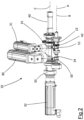
- a wrapping device for product wrappers in accordance with the present invention is generically referred to by the numerical reference 1.
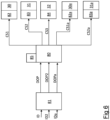
- the device 1 comprises a winder 10 shown on the left in figure 1 and a further winder 10a shown on the right in figure 1 .
- a feeder of products to be wrapped 12 Arranged between the winder 10 and the further winder 10a is a feeder of products to be wrapped 12 (depicted only schematically) rotating about a rotation axis X.
- the feeder of products to be wrapped comprises a plurality of seats (not illustrated) in each of which a corresponding product to be wrapped, partially wrapped by a wrapper material, is arranged.
- Such wrapper material needs to be wound at one or both ends to form a twist or a pair of twists.
- the rotation of the feeder of products to be wrapped sequentially places the partially wrapped products between winder 10 and the further winder 10a.
- the winder 10 and the further winder 10a are configured to make a corresponding twist on the product wrapper.
- the winder 10 and the further winder 10a are arranged facing each other with the product feeder 12 arranged between them.
- the winder 10 and the further winder 10a are structurally identical to each other, except as explicitly described below, and are arranged symmetrically with respect to an ideal plane perpendicular to the rotation axis X of the product feeder 12.
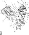
- the winder 10 comprises a gripper 20 mounted at one end 21 of a tubular shaft 22.
- the tubular shaft 22 is mounted inside a containment body 23 from which the end 21 of the tubular shaft 22 emerges.
- the further gripper 20a, the further tubular shaft 22a, the end 21a of the further tubular shaft 22a and the further containment body 23a of the further winder 10a are shown in figure 1 .
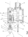
- the tubular shaft 22 is rotatably mounted inside the containment body 23 (not shown in figure 3 ) to rotate about an approach axis A.
- An actuating rod 24 is inserted inside the tubular shaft 22, which is rotationally integral with the tubular shaft 22 through, for example, a pin or shape coupling.
- the actuating rod 24 also rotates about the approach axis A.
- the tubular shaft 22 also slides along the approach axis between a rearward and forward position. In the rearward position, the end 21 of the tubular shaft 22 is distanced from the feeder 11 of products to be wrapped, and in the forward position the end 21 of the tubular shaft 22 is moved closer to the feeder 11 of products to be wrapped.
- the actuating rod 24 slides along an actuating axis B coincident with the approach axis A.
- the actuating rod 24 slides inside the tubular shaft 22 and with respect to the tubular shaft 22.
- the actuating rod 24 slides along the actuating axis B between a rearward and forward position. When the actuating rod 24 is in the forward position, one end 25 of the actuating rod 24 protrudes more from the end 21 of the tubular shaft 22 with respect to when the actuating rod 24 is in the rearward position.
- a first electric motor 30 is provided to drive the translation of the actuating rod 24 along the actuating axis B with respect to the tubular shaft 22.
- a second electric motor 31 is provided to drive the translation of the tubular shaft 22 along the approach axis A.
- a third electric motor 32 is provided to drive the rotation of the tubular shaft 22 and the actuating rod 24 therewith.
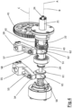
- the third electric motor is connected to a transmission shaft 40 having a rotation axis C parallel to and spaced from the approach axis A.
- a drive shaft of the third electric motor 32 is connected to a speed reducer 33.
- the speed reducer 33 is connected via an input shaft to the transmission shaft of the third electric motor 32 and via an output shaft to the transmission shaft 40.
- the function of the speed reducer 40 is to rotate the motor shaft 40 at a different speed (preferably lower) than the rotation speed of the motor shaft of the third electric motor 32.
- a pinion 41 is keyed to the motor shaft 40, which rotates integrally with the motor shaft 40.
- the pinion 41 is geared with a toothed roller 42 having a rotation axis D parallel to the rotation axis of the transmission shaft 40.
- the toothed roller 42 is also geared with a gear 43 keyed to the tubular shaft 22.
- the rotation of the transmission shaft 40 results in a rotation of the tubular shaft 22.
- Both the pinion 41, toothed roller 42 and gear 43 are spurred, so that gear 43 can translate along the approach axis A (together with the tubular shaft 22) without losing engagement with the toothed roller 42.
- the dimension along the rotation axis D of the toothed roller 42 is greater than the maximum translation length of the tubular shaft 22 along the approach axis A.
- the third electric motor 32 also drives the rotation of the further tubular shaft 22a and the further actuating rod of the further winder 10a.
- the transmission shaft 40 extends between the winder 10 and the further winder 11a until it reaches the further winder 10a.
- the transmission shaft comprises a further pinion geared with a further toothed roller which is geared with a further pinion keyed to the further tubular shaft 22a.
- a first electric motor 30 is provided to drive the actuating rod 24 along the actuating axis B.
- the first electric motor 30 is active on a first fork 50 which is integral along the actuating axis to the actuating rod 24.
- the actuating rod 24 rotates about the actuating axis B with respect to the first fork 50.
- the first fork 50 comprises a through opening slidingly crossed by the actuating rod 24.
- the first fork comprises a shoulder in sliding contact against two abutments 61 integral with the actuating rod 24 and placed on the opposite side with respect to the through opening.
- the second electric motor 31 is active on a second fork 51 which is integral along the approach axis A to the tubular shaft 22.
- the tubular shaft 22 rotates about the approach axis A with respect to the second fork 51.
- the second fork 51 comprises a through opening slidingly crossed by the tubular shaft 22.
- the second fork 51 comprises a shoulder in sliding contact against two abutments 62 integral with the actuating shaft 22 and placed on the opposite side with respect to the through opening.
- the first electric motor 30 drives the first fork 50 via a first control rod 53.
- the first electric motor 30 comprises a rotating drive shaft.
- the first electric motor 30 generates a mechanical moment on the rotating drive shaft, rotating the latter.
- the first control rod 53 comprises a first end 54 hinged to the first fork 50 around a hinge axis perpendicular to the actuating axis B.
- the first control rod 53 comprises a second end 55 opposite the first end 55 stably connected to the output shaft of a speed reducer 56.
- the speed reducer 56 comprises an input shaft connected to the drive shaft of the first electric motor 30.
- the function of the speed reducer 56 is to rotate the first control rod 53 at a different speed (preferably lower) than the rotation speed of the drive shaft of the first electric motor 30.
- the first control rod 53 When the first electric motor 30 is driven to rotate in a first angular direction, the first control rod 53 rotates concordantly in the same angular direction.
- the first control rod 53 sets the first fork 50 in motion in a first direction along the actuating axis B. Such a first direction is directed towards the forward position of the actuating rod 24.
- the first fork 50 drags the actuating rod 24 towards the forward position in translation.
- the first control rod 53 rotates concordantly in the same angular direction.
- the first actuating rod 53 sets the first fork 50 in motion in a second direction along the actuating axis B. Such a second direction is directed towards the rearward position of the actuating rod 24.
- the first fork 50 drags the actuating rod 24 towards the rearward position in translation.
- the second electric motor 31 drives the second fork 51 via a second control rod 57.
- the second electric motor 31, similar to the first electric motor 30, comprises a rotating drive shaft.
- the second electric motor 31 generates a mechanical moment on the rotating drive shaft, rotating the latter.
- the second control rod 57 comprises a first end 58 hinged to the second fork 51 about a hinge axis perpendicular to the approach axis A.
- the second control rod 57 comprises a second end 59 opposite the first end 58 permanently connected to the output shaft of a speed reducer 60.
- the speed reducer 60 comprises an input shaft connected to the drive shaft of the second electric motor 31.
- the function of the speed reducer 60 is to set the second control rod 57 rotating at a different speed (preferably lower) than the rotation speed of the drive shaft of the second electric motor 31.
- the second control rod 57 When the second electric motor 31 is driven to rotate in a first angular direction, the second control rod 57 rotates concordantly in the same angular direction.
- the second control rod 57 sets the second fork 51 in motion in a first direction along the approach axis A. Such a first direction is directed towards the forward position of the tubular shaft 22.
- the second fork 51 drags the tubular shaft 22 towards the forward position in translation.
- the second control rod 57 rotates concordantly in the same angular direction.
- the second control rod 57 sets the second fork 51 in motion in a second direction along the approach axis A. This second direction is directed towards the rearward position of the tubular shaft 22.
- the second fork 51 drags the tubular shaft 22 towards the rearward position in translation.
- the first electric motor is a linear electric motor and comprises a translatable drive shaft.
- the linear electric motor produces a force on the motor shaft which sets the motor shaft in motion along a straight trajectory, either in a first direction or in a second direction opposite to the first.
- the translation direction of the drive shaft is parallel and preferably coincident with the actuating axis B.
- the drive shaft is connected, either directly or via a return, to the first fork 50.
- the drive shaft sets the first fork 50 in motion in a first direction along the actuating axis B.
- Such a first direction is directed towards the forward position of the actuating rod 24.
- the first fork 50 drags the actuating rod 24 towards the forward position in translation.
- the drive shaft sets the first fork 50 in motion in a second direction along the actuating axis B.
- Such a second direction is directed towards the rearward of the actuating rod 24.
- the first fork 50 drags the actuating rod 24 towards the rearward position in translation.
- the second electric motor is a linear electric motor and comprises a translatable drive shaft.
- the linear electric motor produces a force on the motor shaft which sets the motor shaft in motion along a straight trajectory, either in a first direction or in a second direction opposite to the first.
- the translation direction of the drive shaft is parallel and preferably coincident with the approach axis A.
- the drive shaft is connected, either directly or via a return, to the second fork 51.
- the drive shaft sets the second fork 51 in motion in a first direction along the approach axis A.
- Such a first direction is directed towards the forward position of the tubular shaft 22.
- the second fork 51 drags the tubular shaft 22 towards the forward position in translation.
- the drive shaft sets the second fork 51 in motion in a second direction along the approach axis A.
- Such a second direction is directed towards the rearward position of the tubular shaft 22.
- the second fork 51 drags the tubular shaft 22 towards the rearward position in translation.
- the gripper 20 is integral for translations along the approach axis A to the tubular shaft 22 while the actuating rod 24 is sliding along the actuating axis B with respect to the gripper 20.
- the function of the tubular shaft 22 is to rotate and move the gripper 20 towards and away from the product to be wrapped.
- the purpose of the actuating rod 34 is to open and close the gripper 20.
- the gripper 20 comprises (see figure 5 ) a first jaw 70 and a second jaw 71.
- the first jaw 70 and the second jaw 71 are rotatably mounted about a respective clamping axis G on a gripper body 72.
- the gripper body 72 is constrained to the end 21 of the tubular shaft 22 and comprises a through opening through which the actuating rod 24 is slidingly inserted.
- the first jaw 70 comprises a first toothed wheel 73 hinged in the respective clamping axis G of the first jaw.
- the second jaw 71 comprises a second toothed wheel 74 hinged in the respective clamping axis G of the second jaw.
- the first toothed wheel 73 and the second toothed wheel 74 are permanently engaged on a rack 75 placed at one end of the actuating rod 24.
- the translation of the actuating rod 24 along the actuating axis B causes a translation of the rack 75 and a consequent rotation of the first toothed wheel 73 and the second toothed wheel 74 in opposite angular directions.
- the rotation in opposite angular directions of the first toothed wheel 73 and the second toothed wheel 74 results in respective rotations of the first jaw 70 and the second jaw 71 of the gripper 20.
- a translation of the actuating rod 24 towards the forward position corresponds to rotations of the first jaw 70 and second jaw 71 which close or tend to close the gripper 20.
- a translation of the actuating rod 24 towards the rearward position corresponds to rotations of the first jaw 70 and second jaw 71 which open or tend to open the gripper 20.
- the device 1 comprises a control unit 80 (diagrammed in figure 6 ).
- the control unit 80 is associated with a user interface 81 (also diagrammed in figure 6 ).
- the user interface 81 is configured to receive at least one input datum ID representing a desired operating parameter DOP of the gripper 20.
- Such a desired operating parameter SOP is a parameter which identifies a user-desired behaviour of the gripper 20 during its operation in a twist closing process of the end of the wrapper. Such a desired behaviour can be changed by the user by changing the input data ID according to specific usage requirements.
- such a desired operating parameter DOP can be the translation distance which the tubular shaft 20 must travel during a translation along the approach axis A towards the forward position.
- the desired operating parameter SOP is related to the distance at which the gripper 20 is to be brought to the start of the operation to create the twist closure.
- a further example of such a desired operating parameter DOP can be the translation distance which the tubular shaft 20 must travel during a translation along the approach axis A to the rearward position.
- the desired operating parameter DOP is related to the distance at which the gripper 20 is to be brought at the end of the operation to create the twist closure.
- a further example of such a desired operating parameter DOP can be the point, along the approach axis A and during translation of the tubular shaft toward the forward position, at which a closing movement of the first jaw 70 and the second jaw 71 of the gripper 20 begins.
- Such a desired operating parameter DOP can be the point, along the approach axis A and during the movement of the tubular shaft toward the rearward position, at which an opening movement of the first jaw 70 and the second jaw 71 of the gripper 20 begins.
- Such a desired operating parameter DOP could be the point, along the approach axis A, at which an opening movement of the first jaw 70 and the second jaw 71 ends or at which a closing movement of the first jaw 70 and the second jaw 71 ends.
- Such a desired operating parameter DOP can be the distance travelled by the tubular shaft 22 along the approach axis A during which the complete closing of the first jaw 70 and the second jaw 71 occurs, or during which the complete opening of the first jaw 70 and the second jaw 71 of the gripper 20 occurs.
- Such a desired operating parameter DOP could be the maximum rotation in opening of the first jaw 70 and the second jaw 71 or the maximum rotation in closing of the first jaw 70 and the second jaw 71 of the gripper 20.
- Another example of such a desired operating parameter DOP can be the clamping torque of the first jaw 70 and the second jaw 71 of the gripper 20.
- the user interface 81 is configured to receive a plurality of input data ID each representative of a desired operating parameter DOP of the gripper 20.
- the control unit 80 is configured at hardware, software and/or firmware level to obtain the desired operating parameters DOP from the input data ID and determine a gripper 20 law of motion from the derived desired operating parameters DOP.
- the control unit comprises, for example, a processor 85 configured for this purpose.
- Such a law of motion of the gripper 20 expresses, e.g., in respective position/time diagrams and/or in respective mathematical functions, the position of the gripper 20 (or of a point representative of the position of the gripper 20) in time and the degree of opening and closing of first jaw 70 and second jaw 71 (or of points representative of the position of the first jaw 70 and second jaw 71) in time.
- control unit 80 is configured to determine the law of motion of the gripper 20 by interpolating the desired operating parameters DOP with preset operating parameters POP.
- Such preset operating parameters POP are representative of positions which the gripper 20 must necessarily reach over time in order to obtain the desired behaviour.
- the desired operating parameters DOP can be expressed in terms of a plurality of points representing the desired position of the gripper 20 in time and the desired position of the first jaw 70 and the second jaw 71 in time.
- the preset operating parameters POP can be expressed in terms of a plurality of points representing the required position of the gripper 20 in time and the required position of the first jaw 70 and the second jaw 71 in time.
- the control unit 80 is configured, once the law of motion of the gripper 20 has been determined, to break down such a law of motion into a first law of motion of the actuating rod 24 and a second law of motion of the tubular shaft 22.
- the first law of motion of the actuating rod 24 and the second law of motion of the tubular shaft 22 are determined by the control unit 80 so that the simultaneous actuation of the actuating rod 24 according to the first law of motion and the tubular shaft 22 according to the second law of motion results in the actuation of the gripper 20 according to its law of motion.
- the first law of motion expresses, e.g., in a position/time diagram and/or in a respective mathematical function, the position of the actuating rod 24 (or of a point representative of the position of the actuating rod 24) along the actuating axis B in time.
- the second law of motion expresses, e.g., in a position/time diagram and/or in a respective mathematical function, the position of the tubular shaft 22 (or of a point representative of the position of the tubular shaft 22) along the approach axis A in time.
- the control unit 80 is configured to generate a first control signal CS1 representing the first law of motion.
- the first control signal CS1 represents the position of the actuating rod 24 (or of a point representative of the position of the actuating rod 24) along the actuating axis B in time.
- the first control signal CS1 is sent to a driver 82 of the first electric motor 30 to actuate the first electric motor 30.
- the control unit 80 is also configured to generate a second control signal CS2 representing the second law of motion.
- the second control signal CS2 represents the position of the tubular shaft 22 (or a point representative of the position of the tubular shaft 22) along the approach axis A in time.
- the second control signal CS2 is sent to a driver 83 of the second electric motor 31 to actuate the second electric motor 31.
- the control unit 80 is also configured to generate a third control signal CS3 and send it to a driver 84 of the third electric motor 32.
- the third control signal CS3 is generated so as to rotate the tubular shaft during the entire twist winding process of the end of the wrapper.
- the third control signal CS3 can be calculated by the control unit 80 from a second input data ID2 entered in the user data entry interface 81.
- This second input data ID2 is representative of a desired rotation speed OP2 of the gripper 20 and the further gripper 20a when present.
- the desired rotation speed DOP2 can be constant or variable in time.
- control unit 80 is configured to generate a further first control signal CS1a and an further control signal CS2a and send them to respective drivers 82a, 83a of the further first electric motor 30a and the further second electric motor 31a of the further winder 10a.
- Such a further first control signal CS1a and further control signal CS2a are generated from a further at least one input data IDa entered into the user data entry interface 81 and representative of a further desired operating parameter DOpa of the further gripper 20a as described above.
- said further desired operating parameter DOpa in addition to the examples mentioned in connection with the operating parameter DOP, can also be the time lag between the start of the closing or opening of the further first jaw and further second jaw with respect to the opening or closing of the first jaw and second jaw.
- the further operating parameter DOpa and the operating parameter DOP can also be variable as a function of the desired set rotation speed DOP2.
Landscapes
- Engineering & Computer Science (AREA)
- Mechanical Engineering (AREA)
- Manipulator (AREA)
- Containers And Plastic Fillers For Packaging (AREA)
- Transmission Devices (AREA)
- Basic Packing Technique (AREA)
Applications Claiming Priority (1)
| Application Number | Priority Date | Filing Date | Title |
|---|---|---|---|
| IT102022000001418A IT202200001418A1 (it) | 2022-01-28 | 2022-01-28 | Dispositivo per l’avvolgimento di incarti di prodotti |
Publications (2)
| Publication Number | Publication Date |
|---|---|
| EP4219322A1 EP4219322A1 (en) | 2023-08-02 |
| EP4219322B1 true EP4219322B1 (en) | 2024-10-16 |
Family
ID=81328629
Family Applications (1)
| Application Number | Title | Priority Date | Filing Date |
|---|---|---|---|
| EP23151790.5A Active EP4219322B1 (en) | 2022-01-28 | 2023-01-16 | Wrapping device for product wrappers |
Country Status (7)
| Country | Link |
|---|---|
| US (1) | US11945612B2 (enExample) |
| EP (1) | EP4219322B1 (enExample) |
| JP (1) | JP2023110864A (enExample) |
| CN (1) | CN116002148A (enExample) |
| CA (1) | CA3185487A1 (enExample) |
| IT (1) | IT202200001418A1 (enExample) |
| MX (1) | MX2023001151A (enExample) |
Family Cites Families (16)
| Publication number | Priority date | Publication date | Assignee | Title |
|---|---|---|---|---|
| US1743666A (en) * | 1926-04-19 | 1930-01-14 | Firm Fr Hesser Maschinenfabrik | Machine for wrapping loaves of bread |
| US2046262A (en) * | 1934-12-15 | 1936-06-30 | Forgrove Mach | Machine for wrapping sweets and the like |
| GB485499A (en) | 1937-03-02 | 1938-05-20 | Forgrove Mach | Improvements in or relating to machines for wrapping sweets and the like |
| GB808881A (en) * | 1954-05-19 | 1959-02-11 | Reginald Turner | Improvements in and relating to machines for wrapping articles |
| GB1271195A (en) * | 1970-07-22 | 1972-04-19 | Nagema Veb K | Wrapping machine |
| IT1001430B (it) * | 1973-12-20 | 1976-04-20 | Gd Spa | Congegno di apertura e chiusura dei cosiddetti manini dei disposi tivi attorcigliatori associabili alle macchine incartatrici di ca ramelle e simili articoli per la determinazione dell involucro tu bolare nelle fogge d incarto cosid dette a semplice cestello o doppio fiocco |
| DE2420190A1 (de) | 1974-04-26 | 1975-11-06 | Haensel Otto Gmbh | Vorrichtung an bonboneinwickelmaschinen zum herstellen eines dreheinschlages |
| DD130647B1 (de) | 1977-04-21 | 1981-02-25 | Werner Kmoch | Bonboneinwickelmaschine mit gegenueberliegenden drehkoepfen |
| DD153866A1 (de) * | 1980-11-20 | 1982-02-10 | Heinz Lauerbach | Bonboneinwickelmaschine mit staendig umlaufenden drehgreifern |
| IT1156648B (it) | 1982-08-18 | 1987-02-04 | Risvin Ricerche Sviluppo Ind | Apparecchiatura per incartare in movimento continuo caramelle od articoli similari nella cosiddetta foggia d'incarto a doppio fiocco |
| JP3583777B2 (ja) * | 1992-01-21 | 2004-11-04 | エス・アール・アイ・インターナシヨナル | テレオペレータシステムとテレプレゼンス法 |
| IT1266270B1 (it) * | 1993-02-24 | 1996-12-27 | Azionaria Costruzioni Acma Spa | Unita' operatrice per la manipolazione di prodotti in movimento. |
| US5814038A (en) * | 1995-06-07 | 1998-09-29 | Sri International | Surgical manipulator for a telerobotic system |
| US5649956A (en) * | 1995-06-07 | 1997-07-22 | Sri International | System and method for releasably holding a surgical instrument |
| TW201238723A (en) * | 2011-01-31 | 2012-10-01 | Robotex Inc | Robotic arm system |
| US10807250B2 (en) * | 2016-04-07 | 2020-10-20 | Biomet Manufacturing, Llc | Method and apparatus for processing orthopedic components |
-
2022
- 2022-01-28 IT IT102022000001418A patent/IT202200001418A1/it unknown
- 2022-12-21 CA CA3185487A patent/CA3185487A1/en active Pending
- 2022-12-27 JP JP2022209732A patent/JP2023110864A/ja active Pending
-
2023
- 2023-01-16 EP EP23151790.5A patent/EP4219322B1/en active Active
- 2023-01-16 CN CN202310061352.7A patent/CN116002148A/zh active Pending
- 2023-01-26 MX MX2023001151A patent/MX2023001151A/es unknown
- 2023-01-27 US US18/102,203 patent/US11945612B2/en active Active
Also Published As
| Publication number | Publication date |
|---|---|
| US11945612B2 (en) | 2024-04-02 |
| IT202200001418A1 (it) | 2023-07-28 |
| EP4219322A1 (en) | 2023-08-02 |
| MX2023001151A (es) | 2023-07-31 |
| CN116002148A (zh) | 2023-04-25 |
| CA3185487A1 (en) | 2023-07-28 |
| JP2023110864A (ja) | 2023-08-09 |
| US20230242290A1 (en) | 2023-08-03 |
Similar Documents
| Publication | Publication Date | Title |
|---|---|---|
| RU2561260C2 (ru) | Машина для обертывания продуктов | |
| EP4219322B1 (en) | Wrapping device for product wrappers | |
| EP3129294B1 (en) | Wrapping apparatus | |
| US3968627A (en) | Twist finger device for a candy wrapping machine | |
| US8434988B2 (en) | Rotary seamer | |
| GB2125364A (en) | Sweet wrapping apparatus | |
| JP4876796B2 (ja) | 産業用ロボットのハンド装置 | |
| WO2023214267A1 (en) | Method for changing wrapping material in wrapping devices | |
| BR102023001590A2 (pt) | Dispositivo de embrulho para embrulhadores de produto | |
| EP2217392B1 (en) | Rotary seamer | |
| CN103635304B (zh) | 用于成形和密封管状包装容器的开口端的密封单元及用于校准密封单元的方法 | |
| ITUB20150419A1 (it) | Assieme per la realizzazione di occhielli delle gabbiette per tappi di bevande spumanti. | |
| WO2025011731A1 (en) | Smart manipulator for manipulating containers with compact motor group | |
| US3968628A (en) | Twist finger apparatus for wrapping candies and the like | |
| US8696414B2 (en) | Automatic displacer clearance adjustment | |
| JP2023110864A5 (enExample) | ||
| KR101880121B1 (ko) | 로타리 자동 포장기의 백 오픈장치 | |
| EP0614813B1 (en) | Operating unit for handling moving products | |
| EP2123561B1 (en) | A device for producing packages of sheet material containing a product and having at least one twisted end, corresponding process and apparatus | |
| NL9220024A (nl) | Transportinrichting voor snoep. | |
| IT8203510A1 (it) | Dispositivo manipolatore per macchine incartatrici, particolarmente di caramelle e prodotti similari, a movimento continuo | |
| IT8203511A1 (it) | Apparecchiatura per incartare in movimento continuo caramelle od articoli similari nella cosiddetta foggia d'incarto a doppio fiocco | |
| ITBO990194A1 (it) | Dispositivo per la chiusura a fiocco dell' incarto di apparecchiatureper incartare prodotti dolciari e simili . |
Legal Events
| Date | Code | Title | Description |
|---|---|---|---|
| PUAI | Public reference made under article 153(3) epc to a published international application that has entered the european phase |
Free format text: ORIGINAL CODE: 0009012 |
|
| STAA | Information on the status of an ep patent application or granted ep patent |
Free format text: STATUS: THE APPLICATION HAS BEEN PUBLISHED |
|
| AK | Designated contracting states |
Kind code of ref document: A1 Designated state(s): AL AT BE BG CH CY CZ DE DK EE ES FI FR GB GR HR HU IE IS IT LI LT LU LV MC ME MK MT NL NO PL PT RO RS SE SI SK SM TR |
|
| STAA | Information on the status of an ep patent application or granted ep patent |
Free format text: STATUS: REQUEST FOR EXAMINATION WAS MADE |
|
| 17P | Request for examination filed |
Effective date: 20240102 |
|
| RBV | Designated contracting states (corrected) |
Designated state(s): AL AT BE BG CH CY CZ DE DK EE ES FI FR GB GR HR HU IE IS IT LI LT LU LV MC ME MK MT NL NO PL PT RO RS SE SI SK SM TR |
|
| RIC1 | Information provided on ipc code assigned before grant |
Ipc: B65B 59/00 20060101ALI20240404BHEP Ipc: B65B 51/00 20060101ALI20240404BHEP Ipc: B65B 11/14 20060101ALI20240404BHEP Ipc: B65B 25/00 20060101AFI20240404BHEP |
|
| GRAP | Despatch of communication of intention to grant a patent |
Free format text: ORIGINAL CODE: EPIDOSNIGR1 |
|
| STAA | Information on the status of an ep patent application or granted ep patent |
Free format text: STATUS: GRANT OF PATENT IS INTENDED |
|
| INTG | Intention to grant announced |
Effective date: 20240531 |
|
| GRAS | Grant fee paid |
Free format text: ORIGINAL CODE: EPIDOSNIGR3 |
|
| GRAA | (expected) grant |
Free format text: ORIGINAL CODE: 0009210 |
|
| STAA | Information on the status of an ep patent application or granted ep patent |
Free format text: STATUS: THE PATENT HAS BEEN GRANTED |
|
| AK | Designated contracting states |
Kind code of ref document: B1 Designated state(s): AL AT BE BG CH CY CZ DE DK EE ES FI FR GB GR HR HU IE IS IT LI LT LU LV MC ME MK MT NL NO PL PT RO RS SE SI SK SM TR |
|
| REG | Reference to a national code |
Ref country code: GB Ref legal event code: FG4D |
|
| REG | Reference to a national code |
Ref country code: CH Ref legal event code: EP |
|
| REG | Reference to a national code |
Ref country code: IE Ref legal event code: FG4D |
|
| REG | Reference to a national code |
Ref country code: DE Ref legal event code: R096 Ref document number: 602023000710 Country of ref document: DE |
|
| P01 | Opt-out of the competence of the unified patent court (upc) registered |
Free format text: CASE NUMBER: APP_60715/2024 Effective date: 20241112 |
|
| REG | Reference to a national code |
Ref country code: LT Ref legal event code: MG9D |
|
| REG | Reference to a national code |
Ref country code: NL Ref legal event code: MP Effective date: 20241016 |
|
| REG | Reference to a national code |
Ref country code: AT Ref legal event code: MK05 Ref document number: 1732755 Country of ref document: AT Kind code of ref document: T Effective date: 20241016 |
|
| PG25 | Lapsed in a contracting state [announced via postgrant information from national office to epo] |
Ref country code: NL Free format text: LAPSE BECAUSE OF FAILURE TO SUBMIT A TRANSLATION OF THE DESCRIPTION OR TO PAY THE FEE WITHIN THE PRESCRIBED TIME-LIMIT Effective date: 20241016 |
|
| PG25 | Lapsed in a contracting state [announced via postgrant information from national office to epo] |
Ref country code: NL Free format text: LAPSE BECAUSE OF FAILURE TO SUBMIT A TRANSLATION OF THE DESCRIPTION OR TO PAY THE FEE WITHIN THE PRESCRIBED TIME-LIMIT Effective date: 20241016 |
|
| PG25 | Lapsed in a contracting state [announced via postgrant information from national office to epo] |
Ref country code: IS Free format text: LAPSE BECAUSE OF FAILURE TO SUBMIT A TRANSLATION OF THE DESCRIPTION OR TO PAY THE FEE WITHIN THE PRESCRIBED TIME-LIMIT Effective date: 20250216 Ref country code: PT Free format text: LAPSE BECAUSE OF FAILURE TO SUBMIT A TRANSLATION OF THE DESCRIPTION OR TO PAY THE FEE WITHIN THE PRESCRIBED TIME-LIMIT Effective date: 20250217 Ref country code: HR Free format text: LAPSE BECAUSE OF FAILURE TO SUBMIT A TRANSLATION OF THE DESCRIPTION OR TO PAY THE FEE WITHIN THE PRESCRIBED TIME-LIMIT Effective date: 20241016 |
|
| PGFP | Annual fee paid to national office [announced via postgrant information from national office to epo] |
Ref country code: DE Payment date: 20250129 Year of fee payment: 3 |
|
| PG25 | Lapsed in a contracting state [announced via postgrant information from national office to epo] |
Ref country code: FI Free format text: LAPSE BECAUSE OF FAILURE TO SUBMIT A TRANSLATION OF THE DESCRIPTION OR TO PAY THE FEE WITHIN THE PRESCRIBED TIME-LIMIT Effective date: 20241016 |
|
| PG25 | Lapsed in a contracting state [announced via postgrant information from national office to epo] |
Ref country code: BG Free format text: LAPSE BECAUSE OF FAILURE TO SUBMIT A TRANSLATION OF THE DESCRIPTION OR TO PAY THE FEE WITHIN THE PRESCRIBED TIME-LIMIT Effective date: 20241016 |
|
| PG25 | Lapsed in a contracting state [announced via postgrant information from national office to epo] |
Ref country code: ES Free format text: LAPSE BECAUSE OF FAILURE TO SUBMIT A TRANSLATION OF THE DESCRIPTION OR TO PAY THE FEE WITHIN THE PRESCRIBED TIME-LIMIT Effective date: 20241016 |
|
| PG25 | Lapsed in a contracting state [announced via postgrant information from national office to epo] |
Ref country code: NO Free format text: LAPSE BECAUSE OF FAILURE TO SUBMIT A TRANSLATION OF THE DESCRIPTION OR TO PAY THE FEE WITHIN THE PRESCRIBED TIME-LIMIT Effective date: 20250116 |
|
| PG25 | Lapsed in a contracting state [announced via postgrant information from national office to epo] |
Ref country code: LV Free format text: LAPSE BECAUSE OF FAILURE TO SUBMIT A TRANSLATION OF THE DESCRIPTION OR TO PAY THE FEE WITHIN THE PRESCRIBED TIME-LIMIT Effective date: 20241016 Ref country code: AT Free format text: LAPSE BECAUSE OF FAILURE TO SUBMIT A TRANSLATION OF THE DESCRIPTION OR TO PAY THE FEE WITHIN THE PRESCRIBED TIME-LIMIT Effective date: 20241016 Ref country code: GR Free format text: LAPSE BECAUSE OF FAILURE TO SUBMIT A TRANSLATION OF THE DESCRIPTION OR TO PAY THE FEE WITHIN THE PRESCRIBED TIME-LIMIT Effective date: 20250117 |
|
| PG25 | Lapsed in a contracting state [announced via postgrant information from national office to epo] |
Ref country code: PL Free format text: LAPSE BECAUSE OF FAILURE TO SUBMIT A TRANSLATION OF THE DESCRIPTION OR TO PAY THE FEE WITHIN THE PRESCRIBED TIME-LIMIT Effective date: 20241016 |
|
| PG25 | Lapsed in a contracting state [announced via postgrant information from national office to epo] |
Ref country code: RS Free format text: LAPSE BECAUSE OF FAILURE TO SUBMIT A TRANSLATION OF THE DESCRIPTION OR TO PAY THE FEE WITHIN THE PRESCRIBED TIME-LIMIT Effective date: 20250116 |
|
| PGFP | Annual fee paid to national office [announced via postgrant information from national office to epo] |
Ref country code: TR Payment date: 20250102 Year of fee payment: 3 |
|
| PG25 | Lapsed in a contracting state [announced via postgrant information from national office to epo] |
Ref country code: SM Free format text: LAPSE BECAUSE OF FAILURE TO SUBMIT A TRANSLATION OF THE DESCRIPTION OR TO PAY THE FEE WITHIN THE PRESCRIBED TIME-LIMIT Effective date: 20241016 |
|
| PG25 | Lapsed in a contracting state [announced via postgrant information from national office to epo] |
Ref country code: DK Free format text: LAPSE BECAUSE OF FAILURE TO SUBMIT A TRANSLATION OF THE DESCRIPTION OR TO PAY THE FEE WITHIN THE PRESCRIBED TIME-LIMIT Effective date: 20241016 |
|
| REG | Reference to a national code |
Ref country code: DE Ref legal event code: R097 Ref document number: 602023000710 Country of ref document: DE |
|
| PG25 | Lapsed in a contracting state [announced via postgrant information from national office to epo] |
Ref country code: EE Free format text: LAPSE BECAUSE OF FAILURE TO SUBMIT A TRANSLATION OF THE DESCRIPTION OR TO PAY THE FEE WITHIN THE PRESCRIBED TIME-LIMIT Effective date: 20241016 |
|
| PG25 | Lapsed in a contracting state [announced via postgrant information from national office to epo] |
Ref country code: RO Free format text: LAPSE BECAUSE OF FAILURE TO SUBMIT A TRANSLATION OF THE DESCRIPTION OR TO PAY THE FEE WITHIN THE PRESCRIBED TIME-LIMIT Effective date: 20241016 |
|
| PG25 | Lapsed in a contracting state [announced via postgrant information from national office to epo] |
Ref country code: SK Free format text: LAPSE BECAUSE OF FAILURE TO SUBMIT A TRANSLATION OF THE DESCRIPTION OR TO PAY THE FEE WITHIN THE PRESCRIBED TIME-LIMIT Effective date: 20241016 |
|
| PG25 | Lapsed in a contracting state [announced via postgrant information from national office to epo] |
Ref country code: CZ Free format text: LAPSE BECAUSE OF FAILURE TO SUBMIT A TRANSLATION OF THE DESCRIPTION OR TO PAY THE FEE WITHIN THE PRESCRIBED TIME-LIMIT Effective date: 20241016 |
|
| PG25 | Lapsed in a contracting state [announced via postgrant information from national office to epo] |
Ref country code: IT Free format text: LAPSE BECAUSE OF FAILURE TO SUBMIT A TRANSLATION OF THE DESCRIPTION OR TO PAY THE FEE WITHIN THE PRESCRIBED TIME-LIMIT Effective date: 20241016 |
|
| PLBE | No opposition filed within time limit |
Free format text: ORIGINAL CODE: 0009261 |
|
| STAA | Information on the status of an ep patent application or granted ep patent |
Free format text: STATUS: NO OPPOSITION FILED WITHIN TIME LIMIT |
|
| PG25 | Lapsed in a contracting state [announced via postgrant information from national office to epo] |
Ref country code: SE Free format text: LAPSE BECAUSE OF FAILURE TO SUBMIT A TRANSLATION OF THE DESCRIPTION OR TO PAY THE FEE WITHIN THE PRESCRIBED TIME-LIMIT Effective date: 20241016 |
|
| PG25 | Lapsed in a contracting state [announced via postgrant information from national office to epo] |
Ref country code: LU Free format text: LAPSE BECAUSE OF NON-PAYMENT OF DUE FEES Effective date: 20250116 Ref country code: MC Free format text: LAPSE BECAUSE OF FAILURE TO SUBMIT A TRANSLATION OF THE DESCRIPTION OR TO PAY THE FEE WITHIN THE PRESCRIBED TIME-LIMIT Effective date: 20241016 |
|
| 26N | No opposition filed |
Effective date: 20250717 |
|
| PG25 | Lapsed in a contracting state [announced via postgrant information from national office to epo] |
Ref country code: BE Free format text: LAPSE BECAUSE OF NON-PAYMENT OF DUE FEES Effective date: 20250131 |
|
| PG25 | Lapsed in a contracting state [announced via postgrant information from national office to epo] |
Ref country code: FR Free format text: LAPSE BECAUSE OF NON-PAYMENT OF DUE FEES Effective date: 20250131 |
|
| REG | Reference to a national code |
Ref country code: BE Ref legal event code: MM Effective date: 20250131 |