EP4211001B1 - Rückspiegelanordnung mit verdrehschutz - Google Patents
Rückspiegelanordnung mit verdrehschutz Download PDFInfo
- Publication number
- EP4211001B1 EP4211001B1 EP21740529.9A EP21740529A EP4211001B1 EP 4211001 B1 EP4211001 B1 EP 4211001B1 EP 21740529 A EP21740529 A EP 21740529A EP 4211001 B1 EP4211001 B1 EP 4211001B1
- Authority
- EP
- European Patent Office
- Prior art keywords
- mirror
- holding arm
- mirror assembly
- adjustment device
- rear mirror
- Prior art date
- Legal status (The legal status is an assumption and is not a legal conclusion. Google has not performed a legal analysis and makes no representation as to the accuracy of the status listed.)
- Active
Links
Images

Classifications
-
- B—PERFORMING OPERATIONS; TRANSPORTING
- B60—VEHICLES IN GENERAL
- B60R—VEHICLES, VEHICLE FITTINGS, OR VEHICLE PARTS, NOT OTHERWISE PROVIDED FOR
- B60R1/00—Optical viewing arrangements; Real-time viewing arrangements for drivers or passengers using optical image capturing systems, e.g. cameras or video systems specially adapted for use in or on vehicles
- B60R1/12—Mirror assemblies combined with other articles, e.g. clocks
-
- B—PERFORMING OPERATIONS; TRANSPORTING
- B60—VEHICLES IN GENERAL
- B60R—VEHICLES, VEHICLE FITTINGS, OR VEHICLE PARTS, NOT OTHERWISE PROVIDED FOR
- B60R1/00—Optical viewing arrangements; Real-time viewing arrangements for drivers or passengers using optical image capturing systems, e.g. cameras or video systems specially adapted for use in or on vehicles
- B60R1/02—Rear-view mirror arrangements
- B60R1/04—Rear-view mirror arrangements mounted inside vehicle
-
- B—PERFORMING OPERATIONS; TRANSPORTING
- B60—VEHICLES IN GENERAL
- B60R—VEHICLES, VEHICLE FITTINGS, OR VEHICLE PARTS, NOT OTHERWISE PROVIDED FOR
- B60R1/00—Optical viewing arrangements; Real-time viewing arrangements for drivers or passengers using optical image capturing systems, e.g. cameras or video systems specially adapted for use in or on vehicles
- B60R1/12—Mirror assemblies combined with other articles, e.g. clocks
- B60R1/1207—Mirror assemblies combined with other articles, e.g. clocks with lamps; with turn indicators
-
- B—PERFORMING OPERATIONS; TRANSPORTING
- B62—LAND VEHICLES FOR TRAVELLING OTHERWISE THAN ON RAILS
- B62J—CYCLE SADDLES OR SEATS; AUXILIARY DEVICES OR ACCESSORIES SPECIALLY ADAPTED TO CYCLES AND NOT OTHERWISE PROVIDED FOR, e.g. ARTICLE CARRIERS OR CYCLE PROTECTORS
- B62J29/00—Adaptations or arrangements of mirrors for use on cycles
-
- B—PERFORMING OPERATIONS; TRANSPORTING
- B62—LAND VEHICLES FOR TRAVELLING OTHERWISE THAN ON RAILS
- B62J—CYCLE SADDLES OR SEATS; AUXILIARY DEVICES OR ACCESSORIES SPECIALLY ADAPTED TO CYCLES AND NOT OTHERWISE PROVIDED FOR, e.g. ARTICLE CARRIERS OR CYCLE PROTECTORS
- B62J6/00—Arrangement of optical signalling or lighting devices on cycles; Mounting or supporting thereof; Circuits therefor
- B62J6/22—Warning or information lights
- B62J6/24—Warning or information lights warning or informing the rider, e.g. low fuel warning lights
-
- B—PERFORMING OPERATIONS; TRANSPORTING
- B60—VEHICLES IN GENERAL
- B60R—VEHICLES, VEHICLE FITTINGS, OR VEHICLE PARTS, NOT OTHERWISE PROVIDED FOR
- B60R1/00—Optical viewing arrangements; Real-time viewing arrangements for drivers or passengers using optical image capturing systems, e.g. cameras or video systems specially adapted for use in or on vehicles
- B60R1/12—Mirror assemblies combined with other articles, e.g. clocks
- B60R2001/1215—Mirror assemblies combined with other articles, e.g. clocks with information displays
-
- B—PERFORMING OPERATIONS; TRANSPORTING
- B62—LAND VEHICLES FOR TRAVELLING OTHERWISE THAN ON RAILS
- B62J—CYCLE SADDLES OR SEATS; AUXILIARY DEVICES OR ACCESSORIES SPECIALLY ADAPTED TO CYCLES AND NOT OTHERWISE PROVIDED FOR, e.g. ARTICLE CARRIERS OR CYCLE PROTECTORS
- B62J45/00—Electrical equipment arrangements specially adapted for use as accessories on cycles, not otherwise provided for
-
- B—PERFORMING OPERATIONS; TRANSPORTING
- B62—LAND VEHICLES FOR TRAVELLING OTHERWISE THAN ON RAILS
- B62J—CYCLE SADDLES OR SEATS; AUXILIARY DEVICES OR ACCESSORIES SPECIALLY ADAPTED TO CYCLES AND NOT OTHERWISE PROVIDED FOR, e.g. ARTICLE CARRIERS OR CYCLE PROTECTORS
- B62J6/00—Arrangement of optical signalling or lighting devices on cycles; Mounting or supporting thereof; Circuits therefor
Definitions
- the invention relates to a rear-view mirror arrangement according to the preamble of patent claim 1 and a correspondingly equipped motorcycle.
- Motor vehicles such as motorcycles or scooters, usually have one or two rear-view mirrors to enable the driver to monitor the area behind them while driving.
- a mirror is held in a housing, which in turn is attached to the structure of the vehicle via a support arm.
- the mirror is usually rigidly connected to the housing, so that the mirror can be adjusted via an articulated connection to the support arm.
- electrical components such as lighting elements, indicators or mirror heating are increasingly being incorporated into the mirror housing of motorcycles and are controlled via electrical cables that run inside the support arm from the vehicle structure to the mirror housing.
- the electrical cables are also usually routed through the inside of the joint of the articulated connection.
- the DE 197 52 185 A1 relates to an improved structure for holding a rearview mirror of a motorcycle according to the preamble of claim 1.
- it is intended to provide a structure for holding a rearview mirror which enables the main body of the rearview mirror to be rotated smoothly, gently or uniformly at a portion holding the rearview mirror without generating "shaking".
- the US 2 600 893 A relates to a vehicle with an arm to which the rear-view mirror is rotatably and pivotably attached.
- the ITMI20 120 585 A1 relates to an adjustable rear-view mirror for a motorcycle with a holding arm, via which the mirror housing can be attached to the motorcycle, wherein a locking device of the mirror housing is provided outside the mirror housing.
- the US 2017/253184 A1 refers to a side mirror of a vehicle which produces less wind noise.
- the EN 10 2017 126 294 A1 concerns a rear-view mirror for a vehicle which has a large adjustment range and high stability.
- the KR 101 788 979 B1 relates to a fastening device for a mirror holder, which holds it securely and operates with low wear.
- An object of the invention is to further develop a rear-view mirror arrangement in an advantageous manner, in particular to reduce the risk of damage to to reduce the electrical cables integrated in the rear-view mirror assembly.
- a rearview mirror arrangement for a motorcycle is provided with a mirror holder and a holding arm which is designed to connect the mirror holder to the motorcycle, wherein an adjusting device is arranged between the holding arm and the mirror holder, which is designed to be rotatable at least about a free axis of rotation in order to adjust a relative position of the mirror holder with respect to the holding arm by means of a rotary adjustment (also referred to as a rotary movement).
- the adjusting device comprises a limiting device for limiting the rotary adjustment.
- the rearview mirror arrangement therefore comprises a mirror holder, which can be designed as a mirror housing, for example.
- This can be shaped like a shell, for example, and accommodate a mirror element (for example a mirror glass) in the area of a cavity formed by the shell shape.
- the mirror holder is connected to a first end of the holding arm, which is remote from the vehicle, via the adjustment device.
- a second end which is arranged opposite the first end and close to the vehicle, can be designed to be connectable to a vehicle structure of the motorcycle or (when installed on the motorcycle) can be connected to it.
- the vehicle structure can include, among other things, a handlebar, a vehicle frame and/or a vehicle panel or a vehicle body.
- the connection of the second end of the holding arm to the vehicle structure can be rigid or also articulated.
- the adjustment device is designed to provide the adjustability of the mirror holder relative to the holding arm.
- the adjustment device can be rotated at least about the free axis of rotation. It goes without saying that the adjustment device can also have further, additional degrees of freedom.
- the adjustment device also has the limiting device, which is intended to limit the range of movement of the rotary adjustment around the free axis of rotation.
- the limiting device is therefore designed to limit or block rotation of the mirror holder relative to the holding arm beyond a defined range of movement.
- the limiting device thus represents a rotation protection device that prevents excessive rotation of the mirror housing relative to the holding arm. This reduces wear on the moving parts and connection points that are subject to friction effects, so that a particularly long service life of the adjustment device can be ensured in this way.
- This design of the rearview mirror arrangement is suitable for electrified rearview mirror arrangements that have one or more electrical lines that run between the support arm and the mirror holder.
- the electrical lines are guided inside the support arm from a vehicle structure to the mirror holder, with the electrical lines being guided through the adjustment device.
- the rearview mirror arrangement can have electrical components, such as lighting elements, indicators and/or heating elements, that are assigned to the mirror housing and/or the mirror glass and are supplied with power and/or electrical signals via the electrical lines.
- the limiting device effectively prevents the internal electrical cable(s) from being over-twisted or twisted, thus preventing them from being damaged, for example by a cable break or an electrical contact becoming loose. This ensures a particularly long service life in terms of the electrical connection.
- motor cycles include, among others, motorcycles or motorcycle-like motor vehicles, such as motor scooters, in particular tilting two-, three- or four-wheeled motor scooters, scooters or the like, as well as snowmobiles or quads.
- the adjustment device comprises a ball joint with a ball socket and a ball head guided in the ball socket.
- the ball joint offers the possibility of easily adjusting the mirror holder in its relative position to the holding arm, whereby rotation about the free axis of rotation formed by the ball joint is made possible.
- the ball head can preferably be assigned to the mirror holder and the ball socket to the holding arm.
- the reverse assignment is also possible.
- the ball head can be formed by a housing wall of the mirror holder.
- the ball head is thus an integral part of a mirror housing of the mirror holder.
- the housing wall of the mirror holder can be manufactured using an injection molding or die-casting process and the ball head can be formed in one piece and/or made of the same material as the housing wall.
- the limiting device can be arranged on a side of the housing wall of the mirror holder facing away from the ball socket.
- the limiting device can comprise a locking element with at least one extension, which is provided for acting on at least one stop of the limiting device in at least one end position of the rotational adjustment.
- the at least one stop can be assigned to the mirror holder or its housing wall, for example.
- the locking element can be coupled to the ball socket in a rotationally fixed manner, so that a rotational movement of the mirror holder leads to a rotation of the housing wall and thus of the one or more stops relative to the locking element. If the at least one stop reaches the corresponding extension of the locking element, any further rotational movement in this direction of rotation is blocked.
- the at least one stop therefore restricts freedom of movement to such an extent that the mirror holder can only be rotated by a predetermined angle. In this way, over-rotation of any electrical cables located inside is prevented.
- the at least one stop can be assigned to the locking element and the at least one extension to the housing wall of the mirror holder.
- the locking element can be arranged on a first side of the housing wall and the ball socket on a second side opposite the first side.
- the housing wall is thus positioned between the ball socket and the locking element.
- these can be connected with a connecting means, for example with a screw, or by means of a common arrangement at an end section of the holding arm (in the area of the first end).
- the connecting means or the end section can extend through a correspondingly dimensioned recess in the ball head.
- the adjustment device can comprise a spring element for axially prestressing the adjustment device, wherein the spring element prestresses the locking element with a spring force in the direction of the ball head and the ball socket.
- the spring element can be arranged such that the tensioning force is aligned in a coaxial direction to the connecting means, to the end section of the holding arm and/or to the free axis of rotation.
- the spring element can be designed as a spiral spring and arranged coaxially to the connecting means, to the end section and/or to the free axis of rotation.
- the adjustment device in addition to the rotational adjustment about the free axis of rotation, can be designed to tilt the mirror holder relative to the holding arm.
- the rearview mirror arrangement comprises at least one electrical line that extends from the holding arm through the adjustment device to the mirror holder.
- the holding arm can have a continuous cavity for cable routing along its length.
- Fig.1 shows a rearview mirror arrangement 10 for a motorcycle (not shown) in a partially sectioned side view.
- the rearview mirror arrangement 10 comprises a mirror holder 11 and a holding arm 12, which is designed to connect the mirror holder 11 to the motorcycle, wherein an adjustment device 13 is arranged between the holding arm 12 and the mirror holder 11, which is designed to be rotatable at least about a free rotation axis 14 (rotational adjustment D) in order to adjust a relative position of the mirror holder 11 with respect to the holding arm 12.
- the adjustment device 13 comprises a limiting device 15 for limiting the rotational adjustment D.
- the mirror holder 11 is designed as a shell-shaped mirror housing.
- the shell shape forms a cavity in which a mirror element 16 is arranged and is enclosed by a circumferential edge section 11a of the mirror holder 11.
- the rearview mirror arrangement 10 shown is designed as an electrified rearview mirror arrangement and has an electrical line 17 that runs inside the holding arm 12 into the mirror holder 11.
- This can be provided, for example, to supply electrical components 18 (such as a lighting element and/or a turn signal and/or a heating element) with current and/or electrical signals that are assigned to the mirror holder 11 and/or the mirror glass 16.
- a lighting element 18 of a blind spot warning system is shown as an example.
- the electrical line 17 runs inside through the adjusting device 13.
- the adjusting device 13 comprises a ball joint with a ball socket 13a and a ball head 13b guided in the ball socket 13a, wherein the ball head 13b is assigned to the mirror holder 11 and the ball socket 13a is assigned to the holding arm 12.
- the ball head 13b is formed by the housing wall 11b of the mirror holder 11 and is thus an integral part of the mirror housing of the mirror holder 11.
- the limiting device 15 has a locking element 15a with two extensions 15b, which are provided for acting on two stops 15c of the limiting device 15 in two defined end positions of the rotary adjustment D.
- the two stops 15c are assigned to the mirror holder 11 in the embodiment shown and are accordingly arranged on an inner side 11c of the housing wall 11b.
- the locking element 15a is coupled to the ball socket 13a in a rotationally fixed manner, so that a rotational adjustment D of the mirror holder 11 leads to a rotation of the housing wall 11b and thus of the two stops 15c relative to the locking element 15a. If one or both stops 15c reach the respective extension 15b of the locking element 15a, this 15b blocks any further rotational adjustment D in this direction of rotation.
- the respective stop 15c thus restricts freedom of movement to such an extent that the mirror holder 11 can only be rotated by a predetermined angle (here up to approx. 180°). In this way, over-rotation of the electrical cable inside is prevented.
- the locking element 15a is arranged on a first side of the housing wall 11b and the ball socket 13a is arranged on a second side opposite the first side, so that the housing wall 11b forming the ball head 13b is positioned between the ball socket 13a and the locking element 15a.
- the rotationally fixed arrangement of the locking element 15a relative to the ball socket 13a is provided, for example, by an end section 12e of the holding arm 12, which is arranged at the first end 12a and extends through a correspondingly dimensioned recess 11c of the ball head 13b, and onto which the locking element 15a is attached in a rotationally fixed manner.
- the recess 11c is designed in such a way that when the mirror holder 11 is adjusted, the housing wall 11b with the ball head 13b can still be moved relative to the ball socket 13a and the locking element 15a.
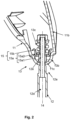
- the adjustment device 13 comprises a spring element 13c designed as a spiral spring 13c for axially pre-tensioning the adjustment device 13, wherein the spring element 13c pre-tensions the locking element 15a with a spring force in the direction of the ball head 13b and the ball socket 13a.
- the tensioning force is aligned in a coaxial direction to the end section 12e and to the free axis of rotation 14.
- the locking element 15a can comprise two elements 15a1, 15a2: a calotte 15a1, the spherical surface of which lies flat against the inner surface 11c of the housing wall 11b in the region of the spherical head 13b even when the mirror holder 11 is twisted and/or tilted.
- the two extensions 15b are formed on a separate disk-shaped element 15a2.
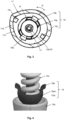
- Fig.4 shows an alternative, second embodiment of the locking element 15a, in which the locking element 15a is formed in one piece.
- the two extensions 15b are formed in one piece and made of the same material on the cap 15a1.
- the locking element 15a can be integrated into the first embodiment (according to Fig. 1 to 3 ) of the rear-view mirror arrangement 10 and replace the two-part locking element 15a there.
Landscapes
- Engineering & Computer Science (AREA)
- Mechanical Engineering (AREA)
- Multimedia (AREA)
- Rear-View Mirror Devices That Are Mounted On The Exterior Of The Vehicle (AREA)
Description
- Die Erfindung betrifft eine Rückspiegelanordnung gemäß dem Oberbegriff des Patentanspruchs 1 sowie ein entsprechend ausgestattetes Kraftrad.
- Krafträder, wie Motorräder oder Motorroller, weisen in der Regel einen oder zwei Rückspiegel auf, um dem Fahrer während der Fahrt die Möglichkeit zu geben, einen Bereich hinter dem Fahrer zu überwachen. Hierbei ist ein Spiegel in einem Gehäuse gehalten, welches wiederum über einen Haltearm an der Struktur des Fahrzeugs befestigt ist. Meist ist der Spiegel starr mit dem Gehäuse verbunden, so dass eine Einstellbarkeit des Spiegels über eine gelenkige Verbindung mit dem Haltearm bereitgestellt wird.
- Mit zunehmender Integration von Assistenzsystemen und Komfortfunktionen finden zunehmend auch bei Krafträdern elektrische Komponenten, wie Leuchtelemente, Blinker oder Spiegelheizungen, Einzug in das Spiegelgehäuse und werden über elektrische Leitungen angesteuert, die im Inneren des Haltearms von der Fahrzeugstruktur bis ins Spiegelgehäuse geführt werden. Üblicherweise werden die elektrischen Leitungen außerdem durch ein Inneres des Gelenks der gelenkigen Verbindung geführt.
- Bei derartig "elektrifizierten" Rückspiegeln kann nicht ausgeschlossen werden, dass durch mehrfaches Verstellen des Spiegels beziehungsweise des Gehäuses über die Lebenszeit des Fahrzeugs die elektrischen Leitungen verdrillt und auf diese Weise beschädigt werden oder hierdurch eine elektrische Kontaktierung gelöst wird.
- Die
DE 197 52 185 A1 bezieht sich auf eine verbesserte Struktur zum Halten eines Rückspiegels eines Motorrads, nach dem Oberbegriff von Anspruch 1. Dort geht es insbesondere darum, eine Struktur zum Halten eines Rückspiegels bereitzustellen, die ermöglicht, dass der Hauptkörper des Rückspiegels glatt, sanft bzw. gleichförmig an einem den Rückspiegel haltenden Abschnitt gedreht werden kann, ohne ein "Rütteln" zu erzeugen. - Die
US 2 600 893 A betrifft ein Fahrzeug mit einem Arm, an welchem der Rückspiegel drehbar und schwenkbar befestigt ist. - Die
IT MI20 120 585 A1 - Die
US 2017/253184 A1 betrifft einen Seitenspiegel eines Fahrzeugs, welcher weniger Windgeräusche produziert. - Die
DE 10 2017 126 294 A1 betrifft einen Rückspiegel für ein Fahrzeug, der einen großen Verstellungsbereich und eine hohe Stabilität aufweist. - Die
KR 101 788 979 B1 - Eine Aufgabe der Erfindung ist es eine Rückspiegelanordnung in vorteilhafter Weise weiterzuentwickeln, insbesondere die Gefahr einer Beschädigung von in der Rückspiegelanordnung integrierten elektrischen Leitungen zu reduzieren.
- Diese Aufgabe wird gelöst mit einer Rückspiegelanordnung gemäß dem Gegenstand des Patentanspruchs 1, sowie einem Kraftrad mit den Merkmalen des Patentanspruchs 9. Vorteilhafte Ausführungsformen ergeben sich aus den jeweils abhängigen Patentansprüchen.
- Demnach wird eine Rückspiegelanordnung für ein Kraftrad bereitgestellt mit einem Spiegelhalter und einem Haltearm, der zum Verbinden des Spiegelhalters mit dem Kraftrad ausgebildet ist, wobei zwischen dem Haltearm und dem Spiegelhalter eine Verstellvorrichtung angeordnet ist, welche zumindest um eine freie Rotationsachse verdrehbar ausgebildet ist, um eine Relativposition des Spiegelhalters gegenüber dem Haltearm mittels einer Drehverstellung (auch als Drehbewegung bezeichnet) zu verstellen. Außerdem umfasst die Verstellvorrichtung eine Begrenzungsvorrichtung zum Beschränken der Drehverstellung.
- Die Rückspiegelanordnung umfasst also einen Spiegelhalter, der beispielsweise als Spiegelgehäuse ausgebildet sein kann. Dieses kann zum Beispiel schalenförmig geformt sein und im Bereich einer von der Schalenform gebildeten Kavität ein Spiegelelement (zum Beispiel ein Spiegelglas) aufnehmen. In jedem Fall ist der Spiegelhalter über die Verstellvorrichtung mit einem fahrzeugfernen, ersten Ende des Haltearms verbunden. Ein dem ersten Ende entgegengesetzt angeordnetes fahrzeugnahes, zweites Ende kann mit einer Fahrzeugstruktur des Kraftrads verbindbar ausgebildet sein beziehungsweise (in einem am Kraftrad verbauten Zustand) mit dieser verbunden sein. Die Fahrzeugstruktur kann unter anderem einen Lenker, ein Fahrzeugrahmen und/oder eine Fahrzeugverkleidung beziehungsweise eine Fahrzeugkarosserie umfassen. Die Verbindung des zweiten Endes des Haltearms mit der Fahrzeugstruktur kann starr oder ebenfalls gelenkig sein.
- Die Verstellvorrichtung ist dazu ausgebildet die Verstellbarkeit des Spiegelhalters gegenüber dem Haltearm bereitzustellen. Hierzu ist die Verstellvorrichtung zumindest um die freie Rotationsachse verdrehbar. Es versteht sich, dass die Verstellvorrichtung darüber hinaus noch weitere, zusätzliche Freiheitsgrade aufweisen kann.
- Außerdem weist die Verstellvorrichtung die Begrenzungsvorrichtung auf, die dazu vorgesehen ist, einen Bewegungsumfang der Drehverstellung um die freie Rotationsachse zu beschränken. Die Begrenzungsvorrichtung ist also dazu ausgebildet, ein Verdrehen des Spiegelhalters gegenüber dem Haltearm über einen definierten Bewegungsumfang hinaus zu begrenzen beziehungsweise zu blockieren. Die Begrenzungsvorrichtung stellt somit einen Verdrehschutz dar, der ein übermäßiges Verdrehen des Spiegelgehäuses gegenüber dem Haltearm verhindert. Dies reduziert einen Verschleiß der beweglichen Teile und Verbindungsstellen, die Reibungseffekten unterworfen sind, so dass eine besonders hohe Langlebigkeit der Verstellvorrichtung auf diese Weise sichergestellt werden kann.
- Diese Ausgestaltung der Rückspiegelanordnung ist für elektrifizierte Rückspiegelanordnungen geeignet, die eine oder mehrere elektrische Leitungen aufweisen, die zwischen dem Haltearm und dem Spiegelhalter verlaufen. Die elektrischen Leitungen werden im Inneren des Haltearms von einer Fahrzeugstruktur bis in den Spiegelhalter geführt, wobei die elektrischen Leitungen durch die Verstellvorrichtung hindurch geführt werden. Beispielsweise kann die Rückspiegelanordnung elektrische Komponenten, wie Leuchtelemente, Blinker und/oder Heizelemente, aufweisen, die dem Spiegelgehäuse und/oder dem Spiegelglas zugeordnet sind und über die elektrischen Leitungen mit Strom und/oder elektrischen Signalen versorgt werden.
- Die Begrenzungsvorrichtung verhindert wirkungsvoll ein Überdrehen beziehungsweise ein Verdrillen der innenliegenden elektrischen Leitung(en) und damit deren Beschädigung, zum Beispiel durch einen Kabelbruch, oder ein Lösen einer elektrischen Kontaktierung. Somit wird hinsichtlich des Aspekts der elektrischen Verbindung eine besonders hohe Langlebigkeit bereitgestellt.
- Als Kraftrad werden im Rahmen dieser Beschreibung unter anderem Motorräder oder motorradähnliche Kraftfahrzeuge, wie Motorroller, insbesondere neigefähige zwei-, drei- oder vierrädrige Motorroller, Scooter oder Dergleichen, sowie Schneemobile oder Quads verstanden.
- Gemäß einer bevorzugten Ausführungsform umfasst die Verstellvorrichtung ein Kugelgelenk mit einer Kugelpfanne und einem in der Kugelpfanne geführten Kugelkopf. Das Kugelgelenk bietet die Möglichkeit, den Spiegelhalter in seiner Relativposition zu dem Haltearm leicht zu verstellen, wobei ein Verdrehen um die durch das Kugelgelenk gebildete freie Rotationsachse ermöglicht wird.
- Hierzu kann vorzugsweise der Kugelkopf dem Spiegelhalter und die Kugelpfanne dem Haltearm zugeordnet sein. Alternativ ist auch eine umgekehrte Zuordnung möglich.
- Des Weiteren kann der Kugelkopf von einer Gehäusewandung des Spiegelhalters gebildet werden. Der Kugelkopf ist somit integraler Bestandteil eines Spiegelgehäuses des Spiegelhalters. Zum Beispiel kann die Gehäusewandung des Spiegelhalters mittels Spritzguss- oder Druckgussverfahren hergestellt und hierbei der Kugelkopf einstückig und/oder materialeinheitlich mit der Gehäusewandung ausgebildet sein/werden.
- Gemäß einer Ausführungsform kann die Begrenzungsvorrichtung auf einer von der Kugelpfanne abgewandten Seite der Gehäusewandung des Spiegelhalters angeordnet sein.
- Außerdem kann die Begrenzungsvorrichtung ein Sperrelement mit mindestens einem Fortsatz umfassen, welcher zur Beaufschlagung mindestens eines Anschlages der Begrenzungsvorrichtung in mindestens einer Endposition der Drehverstellung vorgesehen ist. Hierbei kann der mindestens eine Anschlag beispielsweise dem Spiegelhalter beziehungsweise dessen Gehäusewandung zugeordnet sein. Dagegen kann das Sperrelement drehfest mit der Kugelpfanne gekoppelt sein, so dass eine Drehbewegung des Spiegelhalters zu einer Verdrehung der Gehäusewandung und damit des einen oder der mehreren Anschläge relativ zu dem Sperrelement führt. Erreicht der mindestens eine Anschlag den entsprechenden Fortsatz des Sperrelements, so wird eine darüber hinausgehende, weitere Drehbewegung in dieser Drehrichtung blockiert. Der mindestens eine Anschlag schränkt also eine Bewegungsfreiheit soweit ein, dass der Spiegelhalter nur noch um einen vorbestimmten Winkel verdreht werden kann. Auf diese Weise wird ein Überdrehen der eventuell im Inneren liegenden elektrischen Leitungen unterbunden.
- Selbstverständlich kann analog bei gleicher Wirkungsweise der mindestens eine Anschlag dem Sperrelement und der mindestens eine Fortsatz der Gehäusewandung des Spiegelhalters zugeordnet sein.
- Vorzugsweise kann das Sperrelement auf einer ersten Seite der Gehäusewandung und die Kugelpfanne auf einer der ersten Seite entgegengesetzt angeordneten zweiten Seite angeordnet sein. Damit ist die Gehäusewandung zwischen der Kugelpfanne und dem Sperrelement positioniert.
- Zur Bereitstellung der drehfesten Anordnung des Sperrelements gegenüber der Kugelpfanne können diese mit einem Verbindungsmittel, beispielsweise mit einer Schraube, oder mittels einer gemeinsamen Anordnung an einem Endabschnitt des Haltearms (im Bereich des ersten Endes) verbunden sein. Hierzu kann sich das Verbindungsmittel oder der Endabschnitt durch eine entsprechend dimensionierte Ausnehmung in dem Kugelkopf hindurch erstrecken. Beim Verstellen des Spiegelhalters kann die Gehäusewandung mit dem Kugelkopf trotzdem gegenüber der Kugelpfanne und dem Sperrelement bewegt werden.
- Des Weiteren kann die Verstellvorrichtung ein Federelement zum axialen Vorspannen der Verstellvorrichtung umfassen, wobei das Federelement das Sperrelement mit einer Federkraft in Richtung des Kugelkopfes und der Kugelpfanne vorspannt. Zum Beispiel kann das Federelement derart angeordnet sein, dass die Spannkraft in koaxialer Richtung zu dem Verbindungsmittel, zu dem Endabschnitt des Haltearms und/oder zu der freien Rotationsachse ausgerichtet ist. Zum Beispiel kann das Federelement als Spiralfeder ausgeführt sein und koaxial zu dem Verbindungsmittel, zu dem Endabschnitt und/oder zu der freien Rotationsachse angeordnet sein.
- Des Weiteren kann die Verstellvorrichtung (zusätzlich zum Drehverstellen um die freie Rotationsachse) zum Kippen des Spiegelhalters gegenüber dem Haltearm ausgebildet sein.
- Wie voranstehend beschrieben, umfasst die Rückspiegelanordnung mindestens eine elektrische Leitung, die sich von dem Haltearm durch die Verstellvorrichtung zu dem Spiegelhalter erstreckt. Hierzu kann der Haltearm entlang seiner Länge einen durchgehenden Hohlraum zur Leitungsführung aufweisen.
- Des Weiteren wird ein Kraftrad mit mindestens einer Rückspiegelanordnung bereitgestellt, die mit einer Fahrzeugstruktur des Kraftrades verbunden ist, wobei die Rückspiegelanordnung gemäß der Beschreibung ausgebildet ist. Die Erfindung wird nachfolgend anhand eines Ausführungsbeispiels unter Bezugnahme auf die Zeichnungen näher erläutert. Es zeigen.
- Fig. 1:
- eine Rückspiegelanordnung gemäß der Beschreibung,
- Fig. 2:
- eine Detailansicht einer Verstellvorrichtung der Rückspiegelanordnung gemäß
Fig. 1 , - Fig. 3:
- eine Schnittansicht der Verstellvorrichtung gemäß
Fig. 2 und - Fig. 4:
- eine perspektivische Teilansicht eines Sperrelements der Verstellvorrichtung gemäß
Fig. 3 . -
Fig. 1 zeigt eine Rückspiegelanordnung 10 für ein Kraftrad (nicht dargestellt) in einer teilweise geschnittenen Seitenansicht. Die Rückspiegelanordnung 10 umfasst einen Spiegelhalter 11 und einen Haltearm 12, der zum Verbinden des Spiegelhalters 11 mit dem Kraftrad ausgebildet ist, wobei zwischen dem Haltearm 12 und dem Spiegelhalter 11 eine Verstellvorrichtung 13 angeordnet ist, welche zumindest um eine freie Rotationsachse 14 verdrehbar (Drehverstellung D) ausgebildet ist, um eine Relativposition des Spiegelhalters 11 gegenüber dem Haltearm 12 zu verstellen. Außerdem umfasst die Verstellvorrichtung 13 eine Begrenzungsvorrichtung 15 zum Beschränken der Drehverstellung D. - Der Spiegelhalter 11 ist in der dargestellten Ausführungsform als schalenförmiges Spiegelgehäuse ausgebildet. Die Schalenform bildet eine Kavität in der ein Spiegelelement 16 angeordet und von einem umlaufenden Randabschnitt 11a des Spiegelhalters 11 umschlossen wird.
- Der Spiegelhalter 11 ist über die Verstellvorrichtung 13 mit einem fahrzeugfernen, ersten Ende 12a des Haltearms 12 verbunden. Ein dem ersten Ende 12a entgegengesetzt angeordnetes fahrzeugnahes, zweites Ende 12b ist mit einer Fahrzeugstruktur (nicht dargestellt) des Kraftrads verbindbar ausgebildet. Die Verbindung des zweiten Endes 12b des Haltearms 12 mit der Fahrzeugstruktur kann starr oder ebenfalls gelenkig sein.
- Hierzu umfasst der Haltearm 12 lediglich beispielhaft einen zylinderförmigen Halteabschnitt 12c, der als Bolzen zum Einstecken oder mit einem Gewinde versehen zum Einschrauben in eine entsprechend fahrzeugseitig an der Fahrzeugstruktur vorgesehene Aufnahme (nicht dargestellt) geführt sein kann.
- Wie beschrieben stellt die Verstellvorrichtung 13 die Verstellbarkeit des Spiegelhalters 11 gegenüber dem Haltearm 12 bereit. Hierzu ist die Verstellvorrichtung 13 zumindest um die freie Rotationsachse 14 verdrehbar (Drehverstellung D). Es versteht sich, dass die Verstellvorrichtung 13 darüber hinaus noch weitere, zusätzliche Freiheitsgrade aufweisen kann.
- Um einen Bewegungsumfang der Drehverstellung D um die freie Rotationsachse 14 zu beschränken, weist die Verstellvorrichtung 13 die genannte Begrenzungsvorrichtung 15 auf. Diese 15 ist dazu ausgebildet, ein Verdrehen des Spiegelhalters 11 gegenüber dem Haltearm 12 über einen definierten Bewegungsumfang hinaus zu begrenzen.
- Die dargestellte Rückspiegelanordnung 10 ist als elektrifizierte Rückspiegelanordnung ausgeführt und weist eine elektrische Leitung 17 auf, die innerhalb des Haltearms 12 bis in den Spiegelhalter 11 verläuft. Diese kann beispielsweise zur Versorgung von elektrischen Komponenten 18 (wie einem Leuchtelement und/oder einem Blinker und/oder einem Heizelement) mit Strom und/oder elektrischen Signalen vorgesehen sein, die dem Spiegelhalter 11 und/oder dem Spiegelglas 16 zugeordnet sind. Beispielhaft ist ein Leuchtelement 18 eines Totwinkel-Warnsystems dargestellt. Selbstverständlich können anstelle der einen elektrischen Leitung 17 auch mehrere elektrische Leitungen in gleicher Weise vorgesehen werden. Wie in
Fig. 1 dargestellt, verläuft die elektrische Leitung 17 im Inneren durch die Verstellvorrichtung 13 hindurch. - In der Detailansicht der Verstellvorrichtung 13 gemäß
Fig. 2 ist die elektrische Leitung 17 der besseren Übersichtlichkeit halber ausgeblendet, so dass eine entsprechende rohrförmige Form des Haltearms 12 mit einem entlang seiner Länge verlaufenden Hohlraums 12d erkennbar ist, der zur Aufnahme der elektrischen Leitung 17 vorgesehen ist. - Die Verstellvorrichtung 13 umfasst in der dargestellten Ausführungsform ein Kugelgelenk mit einer Kugelpfanne 13a und einem in der Kugelpfanne 13a geführten Kugelkopf 13b, wobei der Kugelkopf 13b dem Spiegelhalter 11 und die Kugelpfanne 13a dem Haltearm 12 zugeordnet sind.
- Das Kugelgelenk bietet die Möglichkeit, den Spiegelhalter 11 in seiner Relativposition zu dem Haltearm 12 leicht zu verstellen, wobei ein Verdrehen um die durch das Kugelgelenk gebildete freie Rotationsachse 14 ermöglicht wird. Zusätzlich ermöglicht die Ausführung als Kugelgelenk eine (bezüglich der Rotationsachse 14) seitliche Kippbarkeit (Kippbewegung K), so dass der Kugelkopf 13b und damit der Spiegelhalter 11 seitlich gegenüber dem Haltearm 12 gekippt werden kann.
- Gemäß der dargestellten Ausführungsform ist der Kugelkopf 13b von der Gehäusewandung 11b des Spiegelhalters 11 gebildet und somit integraler Bestandteil des Spiegelgehäuses des Spiegelhalters 11.
- Die Begrenzungsvorrichtung 15 ist auf einer von der Kugelpfanne 13a abgewandten Seite des Kugelkopfes 13b angeordnet, also innerhalb des Kugelkopfes 13b beziehungsweise innerhalb der Gehäusewandung 11b des Spiegelhalters 11.
- Wie aus den
Fig. 2 und3 ersichtlich ist, weist die Begrenzungsvorrichtung 15 ein Sperrelement 15a mit zwei Fortsätzen 15b auf, die zur Beaufschlagung von zwei Anschlägen 15c der Begrenzungsvorrichtung 15 in zwei definierten Endpositionen der Drehverstellung D vorgesehen ist. Die beiden Anschläge 15c sind in der dargestellten Ausführungsform dem Spiegelhalter 11 zugeordnet und entsprechend auf einer Innenseite 11c der Gehäusewandung 11b angeordnet. - Das Sperrelement 15a ist drehfest mit der Kugelpfanne 13a gekoppelt, so dass eine Drehverstellung D des Spiegelhalters 11 zu einer Verdrehung der Gehäusewandung 11b und damit der beiden Anschläge 15c gegenüber dem Sperrelement 15a führt. Erreichen einer oder beide Anschläge 15c den jeweiligen Fortsatz 15b des Sperrelements 15a, so wird durch diesen 15b eine darüber hinausgehende, weitere Drehverstellung D in dieser Drehrichtung blockiert. Der jeweilige Anschlag 15c schränkt also eine Bewegungsfreiheit soweit ein, dass der Spiegelhalter 11 nur noch um einen vorbestimmten Winkel (hier bis zu ca. 180°) verdreht werden kann. Auf diese Weise wird ein Überdrehen der im Inneren liegenden elektrischen Leitung unterbunden. Es versteht sich, dass anstelle der zwei Anschläge 15c und deren versetzte Anordnung um 180° auch lediglich ein Anschlag oder mehr als zwei Anschläge vorgesehen werden können, und/oder deren (Winkel-)Abstand zueinander nach Bedarf gewählt werden kann. Gleiches gilt für die Anzahl und Position der Fortsätze 15b des Sperrelements 15a. Es kann auch lediglich ein Fortsatz oder mehr als zwei Fortsätze vorgesehen werden, und/oder deren (Winkel-)Abstand zueinander nach Bedarf gewählt werden.
- Wie aus
Fig. 2 ersichtlich ist das Sperrelement 15a auf einer ersten Seite der Gehäusewandung 11b und die Kugelpfanne 13a auf einer der ersten Seite entgegengesetzt angeordneten zweiten Seite angeordnet, so dass die den Kugelkopf 13b bildende Gehäusewandung 11b zwischen der Kugelpfanne 13a und dem Sperrelement 15a positioniert ist. - Die drehfeste Anordnung des Sperrelements 15a gegenüber der Kugelpfanne 13a wird beispielhaft durch einen Endabschnitt 12e des Haltearms 12 bereitgestellt, der an dem ersten Ende 12a angeordnet ist und sich durch eine entsprechend dimensionierte Ausnehmung 11c des Kugelkopfs 13b hindurch erstreckt, und auf den das Sperrelement 15a drehfest aufgesteckt ist.
- Die Ausnehmung 11c ist derart abgestimmt, dass beim Verstellen des Spiegelhalters 11 die Gehäusewandung 11b mit dem Kugelkopf 13b trotzdem gegenüber der Kugelpfanne 13a und dem Sperrelement 15a bewegt werden kann.
- Des Weiteren umfasst die Verstellvorrichtung 13 ein als Spiralfeder 13c ausgeführtes Federelement 13c zum axialen Vorspannen der Verstellvorrichtung 13, wobei das Federelement 13c das Sperrelement 15a mit einer Federkraft in Richtung des Kugelkopfes 13b und der Kugelpfanne 13a vorspannt. Die Spannkraft ist hierzu in koaxialer Richtung zu dem Endabschnitt 12e und zu der freien Rotationsachse 14 ausgerichtet.
- Wie insbesondere aus
Fig. 2 ersichtlich, kann das Sperrelement 15a gemäß einer ersten Ausführungsform zwei Elemente 15a1, 15a2 umfassen: eine Kalotte 15a1, deren Kugeloberfläche auch bei einer Verdrehung und/oder Verkippung des Spiegelhalters 11 flächig an der inneren Oberfläche 11c der Gehäusewandung 11b im Bereich des Kugelkopfes 13b anliegt. Die beiden Fortsätze 15b sind an einem separaten scheibenförmigen Element 15a2 ausgebildet. -
Fig. 4 zeigt eine alternative, zweite Ausführungsform des Sperrelements 15a, bei der das Sperrelement 15a einstückig ausgebildet ist. Hierbei sind die beiden Fortsätze 15b einstückig und materialeinheitlich an der Kalotte 15a1 integral ausgebildet. Das Sperrelement 15a kann ohne weiteren Änderungsbedarf in die erste Ausführungsform (gemäßFig. 1 bis 3 ) der Rückspiegelanordnung 10 eingesetzt werden und das dortige zweiteilige Sperrelement 15a ersetzen.
Claims (9)
- Rückspiegelanordnung (10) für ein Kraftrad mit einem Spiegelhalter (11) und einem Haltearm (12), der zum Verbinden des Spiegelhalters (11) mit dem Kraftrad ausgebildet ist, wobei zwischen dem Haltearm (12) und dem Spiegelhalter (11) eine Verstellvorrichtung (13) angeordnet ist, welche zumindest um eine freie Rotationsachse (14) verdrehbar ausgebildet ist, um eine Relativposition des Spiegelhalters (11) gegenüber dem Haltearm (12) zu verstellen, wobei die Verstellvorrichtung (13) eine Begrenzungsvorrichtung (15) zum Beschränken der Drehverstellung (D) umfasst, dadurch gekennzeichnet dass die Rückspiegelanordnung (10) mindestens eine elektrische Leitung (17) umfasst, die sich von dem Haltearm (12) durch die Verstellvorrichtung (13) zu dem Spiegelhalter (11) erstreckt..
- Rückspiegelanordnung (10) nach Anspruch 1, dadurch gekennzeichnet, dass die Verstellvorrichtung (13) ein Kugelgelenk mit einer Kugelpfanne (13a) und einem in der Kugelpfanne (13a) geführten Kugelkopf (13b) umfasst.
- Rückspiegelanordnung (10) nach Anspruch 2, dadurch gekennzeichnet, dass der Kugelkopf (13b) dem Spiegelhalter (11) und die Kugelpfanne (13a) dem Haltearm (12) zugeordnet ist.
- Rückspiegelanordnung (10) nach Anspruch 2 oder 3, dadurch gekennzeichnet, dass der Kugelkopf (13b) von einer Gehäusewandung (11b) des Spiegelhalters (11) gebildet wird.
- Rückspiegelanordnung (10) nach einem der Ansprüche 2 bis 4, dadurch gekennzeichnet, dass die Begrenzungsvorrichtung (15) auf einer von der Kugelpfanne (13a) abgewandten Seite der Gehäusewandung (11b) angeordnet ist.
- Rückspiegelanordnung (10) nach einem der Ansprüche 1 bis 5, dadurch gekennzeichnet, dass die Begrenzungsvorrichtung (15) ein Sperrelement (15a) mit mindestens einem Fortsatz (15b) umfasst, welcher zur Beaufschlagung mindestens eines Anschlages (15c) der Begrenzungsvorrichtung (15) in jeweils einer Endposition der Drehverstellung (D) vorgesehen ist.
- Rückspiegelanordnung (10) nach Anspruch 6, dadurch gekennzeichnet, dass die Verstellvorrichtung (13) ein Federelement (13c) zum axialen Vorspannen der Verstellvorrichtung (13) umfasst, wobei das Federelement (13c) das Sperrelement (15a) mit einer Federkraft in Richtung des Kugelkopfes (13b) und der Kugelpfanne (13a) beaufschlagt.
- Rückspiegelanordnung (10) nach einem der Ansprüche 1 bis 7, dadurch gekennzeichnet, dass die Verstellvorrichtung (13) zum Kippen (K) des Spiegelhalters (11) gegenüber dem Haltearm (12) ausgebildet ist.
- Kraftrad mit mindestens einer Rückspiegelanordnung (10), die mit einer Fahrzeugstruktur verbunden ist, dadurch gekennzeichnet, dass die Rückspiegelanordnung (10) gemäß einem der Patentansprüche 1 bis 8 ausgebildet ist.
Applications Claiming Priority (2)
| Application Number | Priority Date | Filing Date | Title |
|---|---|---|---|
| DE102020123262.4A DE102020123262A1 (de) | 2020-09-07 | 2020-09-07 | Rückspiegelanordnung mit Verdrehschutz |
| PCT/EP2021/069128 WO2022048816A1 (de) | 2020-09-07 | 2021-07-09 | Rückspiegelanordnung mit verdrehschutz |
Publications (2)
| Publication Number | Publication Date |
|---|---|
| EP4211001A1 EP4211001A1 (de) | 2023-07-19 |
| EP4211001B1 true EP4211001B1 (de) | 2024-08-28 |
Family
ID=76891069
Family Applications (1)
| Application Number | Title | Priority Date | Filing Date |
|---|---|---|---|
| EP21740529.9A Active EP4211001B1 (de) | 2020-09-07 | 2021-07-09 | Rückspiegelanordnung mit verdrehschutz |
Country Status (5)
| Country | Link |
|---|---|
| US (1) | US12583545B2 (de) |
| EP (1) | EP4211001B1 (de) |
| CN (1) | CN116133900B (de) |
| DE (1) | DE102020123262A1 (de) |
| WO (1) | WO2022048816A1 (de) |
Families Citing this family (2)
| Publication number | Priority date | Publication date | Assignee | Title |
|---|---|---|---|---|
| USD1120829S1 (en) * | 2024-03-01 | 2026-03-31 | Rizoma S.R.L. | Motorbike rear view mirror |
| TWI851521B (zh) * | 2024-03-01 | 2024-08-01 | 鈊湛科技有限公司 | 車輛後視鏡 |
Family Cites Families (24)
| Publication number | Priority date | Publication date | Assignee | Title |
|---|---|---|---|---|
| US2600893A (en) * | 1947-05-14 | 1952-06-17 | Frank N Mariani | Knuckle joint for rearvision reflectors |
| DE19521432C2 (de) | 1995-06-15 | 1999-07-01 | Hohe Gmbh & Co Kg | Fahrzeugaußenspiegel mit motorisch schwenkbarem Spiegelkopf |
| US5755526A (en) | 1996-05-23 | 1998-05-26 | Trw Inc. | Ball and socket joint |
| JP3995742B2 (ja) * | 1996-11-28 | 2007-10-24 | 本田技研工業株式会社 | バックミラー支持構造 |
| EP1292931B1 (de) * | 2000-02-11 | 2013-04-03 | SMR Patents S.à.r.l. | Aussenspiegel |
| US6877709B2 (en) * | 2000-12-21 | 2005-04-12 | Donnelly Corporation | Interior rearview mirror assembly with polymeric components |
| US7172298B2 (en) * | 2001-04-27 | 2007-02-06 | Schefenacker Vision Systems Australia Pty Ltd | Power fold mechanism for vehicle mirrors |
| US20030142422A1 (en) * | 2002-01-31 | 2003-07-31 | Spitzer Jamie P. | Vibration-dampened mirror/speaker system for motorcycles |
| JP4086227B2 (ja) * | 2002-12-09 | 2008-05-14 | 本田技研工業株式会社 | バックミラー装置 |
| US8220866B1 (en) * | 2006-05-22 | 2012-07-17 | Ifm Limited, Llc | Assembly for vehicles including adjustable mirrors |
| US7585081B2 (en) * | 2007-09-11 | 2009-09-08 | John Henry Vanderslik | Extendable mirrors for vehicle handlebars |
| US8201800B2 (en) * | 2008-08-06 | 2012-06-19 | Gentex Corporation | Two ball mount with wiring passage |
| US8210695B2 (en) * | 2009-04-30 | 2012-07-03 | Gentex Corporation | Channeled mirror mount |
| DE202011003950U1 (de) | 2011-03-14 | 2012-06-28 | Erwin Müller GmbH | Leuchtspiegel |
| ITMI20120585A1 (it) | 2012-04-11 | 2013-10-12 | Barrac S R L | Specchio retrovisore orientabile per motociclo |
| GB2543246B (en) | 2015-07-29 | 2021-01-13 | Karbon Kinetics Ltd | Handlebar mountable light pipe apparatus for a bicycle |
| CN105383391B (zh) | 2015-11-26 | 2018-04-06 | 重庆奥科伦实业发展有限公司 | 设于汽车内的用于观察汽车外部信息的内后视镜 |
| JP6267734B2 (ja) * | 2016-03-03 | 2018-01-24 | 株式会社石▲崎▼本店 | 車両用サイドミラー |
| KR101788979B1 (ko) | 2016-06-14 | 2017-10-20 | 임국건 | 미러스테이 고정장치 |
| JP6841020B2 (ja) | 2016-11-30 | 2021-03-10 | スズキ株式会社 | ポジション照明装置および車両 |
| CN107264406B (zh) * | 2017-07-28 | 2023-05-19 | 熊晓峰 | 无a、b柱对应盲区的汽车 |
| DE102017126294B4 (de) | 2017-11-09 | 2023-03-09 | Chiung-yao Chen | Rückspiegel für ein Fahrzeug |
| DE102018106012B3 (de) * | 2018-03-15 | 2019-03-07 | Jenoptik Optical Systems Gmbh | Justierbare Spiegelbaugruppe mit Blattfederelement |
| DE102019209556A1 (de) | 2019-06-28 | 2020-12-31 | Ford Global Technologies, Llc | Befestigungsvorrichtung für ein verstellbares Zubehörteil |
-
2020
- 2020-09-07 DE DE102020123262.4A patent/DE102020123262A1/de active Pending
-
2021
- 2021-07-09 US US18/015,648 patent/US12583545B2/en active Active
- 2021-07-09 EP EP21740529.9A patent/EP4211001B1/de active Active
- 2021-07-09 WO PCT/EP2021/069128 patent/WO2022048816A1/de not_active Ceased
- 2021-07-09 CN CN202180061351.1A patent/CN116133900B/zh active Active
Also Published As
| Publication number | Publication date |
|---|---|
| CN116133900B (zh) | 2026-01-09 |
| CN116133900A (zh) | 2023-05-16 |
| DE102020123262A1 (de) | 2022-03-10 |
| WO2022048816A1 (de) | 2022-03-10 |
| US12583545B2 (en) | 2026-03-24 |
| EP4211001A1 (de) | 2023-07-19 |
| US20230249774A1 (en) | 2023-08-10 |
Similar Documents
| Publication | Publication Date | Title |
|---|---|---|
| EP3114005B1 (de) | Lenksäule für ein kraftfahrzeug | |
| DE602004001923T2 (de) | Schwenkbare Lenksäule | |
| EP1225067B1 (de) | Anhängerkupplung | |
| EP4211001B1 (de) | Rückspiegelanordnung mit verdrehschutz | |
| DE10154080A1 (de) | Halterung für ein justierbares Gehäuse | |
| EP2828680B1 (de) | Sensorhalterung für einen sensor zur objektdetektion | |
| DE60202335T2 (de) | Fahrzeugspiegel | |
| DE69911536T2 (de) | Schwenkverriegelung für eine schwenkbare Lenksäule | |
| EP3601013B1 (de) | Verstellbare lenksäule für ein kraftfahrzeug | |
| DE102009058450B3 (de) | Längseinsteller für einen Fahrzeugsitz mit Spindel und Spindelhalter | |
| EP4134279B1 (de) | Indirektes rücksichtsystem mit indexgeometrie umfassend eine verstellkugel mit überdrehindexierung | |
| DE19721790C1 (de) | Lenkradbefestigung | |
| EP1184223A2 (de) | Aussenrückblickspiegel für Kraftfahrzeuge | |
| DE3433513C2 (de) | ||
| DE102015219806B4 (de) | Spiegelaktuator für ein Fahrzeug | |
| DE60014565T2 (de) | Exzentrisch einstellbare Mutter | |
| DE202023104401U1 (de) | Lenkervorbau | |
| EP0221255A2 (de) | Fahrzeugspiegel | |
| EP3665066A1 (de) | Radaufhängung | |
| DE102021116803A1 (de) | Halter, Baukasten und Verfahren zum Montieren eines Halters | |
| EP1086865B1 (de) | Befestigungsanordnung für eine Scheibenwischeranlage | |
| EP0226747B1 (de) | Fahrzeug-Aussenspiegelhalterung | |
| DE102022107619B3 (de) | Aktuatorbaugruppe, Rückblickvorrichtung und Fahrzeug | |
| DE102008050012B4 (de) | Kugelgelenk | |
| DE69916882T2 (de) | Kraftfahrzeugrückblickspiegel |
Legal Events
| Date | Code | Title | Description |
|---|---|---|---|
| STAA | Information on the status of an ep patent application or granted ep patent |
Free format text: STATUS: UNKNOWN |
|
| STAA | Information on the status of an ep patent application or granted ep patent |
Free format text: STATUS: THE INTERNATIONAL PUBLICATION HAS BEEN MADE |
|
| PUAI | Public reference made under article 153(3) epc to a published international application that has entered the european phase |
Free format text: ORIGINAL CODE: 0009012 |
|
| STAA | Information on the status of an ep patent application or granted ep patent |
Free format text: STATUS: REQUEST FOR EXAMINATION WAS MADE |
|
| 17P | Request for examination filed |
Effective date: 20230320 |
|
| AK | Designated contracting states |
Kind code of ref document: A1 Designated state(s): AL AT BE BG CH CY CZ DE DK EE ES FI FR GB GR HR HU IE IS IT LI LT LU LV MC MK MT NL NO PL PT RO RS SE SI SK SM TR |
|
| DAV | Request for validation of the european patent (deleted) | ||
| DAX | Request for extension of the european patent (deleted) | ||
| GRAP | Despatch of communication of intention to grant a patent |
Free format text: ORIGINAL CODE: EPIDOSNIGR1 |
|
| STAA | Information on the status of an ep patent application or granted ep patent |
Free format text: STATUS: GRANT OF PATENT IS INTENDED |
|
| INTG | Intention to grant announced |
Effective date: 20240521 |
|
| GRAS | Grant fee paid |
Free format text: ORIGINAL CODE: EPIDOSNIGR3 |
|
| GRAA | (expected) grant |
Free format text: ORIGINAL CODE: 0009210 |
|
| STAA | Information on the status of an ep patent application or granted ep patent |
Free format text: STATUS: THE PATENT HAS BEEN GRANTED |
|
| AK | Designated contracting states |
Kind code of ref document: B1 Designated state(s): AL AT BE BG CH CY CZ DE DK EE ES FI FR GB GR HR HU IE IS IT LI LT LU LV MC MK MT NL NO PL PT RO RS SE SI SK SM TR |
|
| REG | Reference to a national code |
Ref country code: CH Ref legal event code: EP |
|
| REG | Reference to a national code |
Ref country code: DE Ref legal event code: R096 Ref document number: 502021004964 Country of ref document: DE |
|
| REG | Reference to a national code |
Ref country code: IE Ref legal event code: FG4D Free format text: LANGUAGE OF EP DOCUMENT: GERMAN |
|
| REG | Reference to a national code |
Ref country code: LT Ref legal event code: MG9D |
|
| PG25 | Lapsed in a contracting state [announced via postgrant information from national office to epo] |
Ref country code: NO Free format text: LAPSE BECAUSE OF FAILURE TO SUBMIT A TRANSLATION OF THE DESCRIPTION OR TO PAY THE FEE WITHIN THE PRESCRIBED TIME-LIMIT Effective date: 20241128 |
|
| PG25 | Lapsed in a contracting state [announced via postgrant information from national office to epo] |
Ref country code: PT Free format text: LAPSE BECAUSE OF FAILURE TO SUBMIT A TRANSLATION OF THE DESCRIPTION OR TO PAY THE FEE WITHIN THE PRESCRIBED TIME-LIMIT Effective date: 20241230 Ref country code: GR Free format text: LAPSE BECAUSE OF FAILURE TO SUBMIT A TRANSLATION OF THE DESCRIPTION OR TO PAY THE FEE WITHIN THE PRESCRIBED TIME-LIMIT Effective date: 20241129 Ref country code: FI Free format text: LAPSE BECAUSE OF FAILURE TO SUBMIT A TRANSLATION OF THE DESCRIPTION OR TO PAY THE FEE WITHIN THE PRESCRIBED TIME-LIMIT Effective date: 20240828 Ref country code: PL Free format text: LAPSE BECAUSE OF FAILURE TO SUBMIT A TRANSLATION OF THE DESCRIPTION OR TO PAY THE FEE WITHIN THE PRESCRIBED TIME-LIMIT Effective date: 20240828 Ref country code: NL Free format text: LAPSE BECAUSE OF FAILURE TO SUBMIT A TRANSLATION OF THE DESCRIPTION OR TO PAY THE FEE WITHIN THE PRESCRIBED TIME-LIMIT Effective date: 20240828 |
|
| PG25 | Lapsed in a contracting state [announced via postgrant information from national office to epo] |
Ref country code: BG Free format text: LAPSE BECAUSE OF FAILURE TO SUBMIT A TRANSLATION OF THE DESCRIPTION OR TO PAY THE FEE WITHIN THE PRESCRIBED TIME-LIMIT Effective date: 20240828 |
|
| PG25 | Lapsed in a contracting state [announced via postgrant information from national office to epo] |
Ref country code: LV Free format text: LAPSE BECAUSE OF FAILURE TO SUBMIT A TRANSLATION OF THE DESCRIPTION OR TO PAY THE FEE WITHIN THE PRESCRIBED TIME-LIMIT Effective date: 20240828 |
|
| REG | Reference to a national code |
Ref country code: NL Ref legal event code: MP Effective date: 20240828 |
|
| PG25 | Lapsed in a contracting state [announced via postgrant information from national office to epo] |
Ref country code: IS Free format text: LAPSE BECAUSE OF FAILURE TO SUBMIT A TRANSLATION OF THE DESCRIPTION OR TO PAY THE FEE WITHIN THE PRESCRIBED TIME-LIMIT Effective date: 20241228 |
|
| PG25 | Lapsed in a contracting state [announced via postgrant information from national office to epo] |
Ref country code: HR Free format text: LAPSE BECAUSE OF FAILURE TO SUBMIT A TRANSLATION OF THE DESCRIPTION OR TO PAY THE FEE WITHIN THE PRESCRIBED TIME-LIMIT Effective date: 20240828 |
|
| PG25 | Lapsed in a contracting state [announced via postgrant information from national office to epo] |
Ref country code: RS Free format text: LAPSE BECAUSE OF FAILURE TO SUBMIT A TRANSLATION OF THE DESCRIPTION OR TO PAY THE FEE WITHIN THE PRESCRIBED TIME-LIMIT Effective date: 20241128 Ref country code: ES Free format text: LAPSE BECAUSE OF FAILURE TO SUBMIT A TRANSLATION OF THE DESCRIPTION OR TO PAY THE FEE WITHIN THE PRESCRIBED TIME-LIMIT Effective date: 20240828 |
|
| PG25 | Lapsed in a contracting state [announced via postgrant information from national office to epo] |
Ref country code: RS Free format text: LAPSE BECAUSE OF FAILURE TO SUBMIT A TRANSLATION OF THE DESCRIPTION OR TO PAY THE FEE WITHIN THE PRESCRIBED TIME-LIMIT Effective date: 20241128 Ref country code: PT Free format text: LAPSE BECAUSE OF FAILURE TO SUBMIT A TRANSLATION OF THE DESCRIPTION OR TO PAY THE FEE WITHIN THE PRESCRIBED TIME-LIMIT Effective date: 20241230 Ref country code: PL Free format text: LAPSE BECAUSE OF FAILURE TO SUBMIT A TRANSLATION OF THE DESCRIPTION OR TO PAY THE FEE WITHIN THE PRESCRIBED TIME-LIMIT Effective date: 20240828 Ref country code: NO Free format text: LAPSE BECAUSE OF FAILURE TO SUBMIT A TRANSLATION OF THE DESCRIPTION OR TO PAY THE FEE WITHIN THE PRESCRIBED TIME-LIMIT Effective date: 20241128 Ref country code: NL Free format text: LAPSE BECAUSE OF FAILURE TO SUBMIT A TRANSLATION OF THE DESCRIPTION OR TO PAY THE FEE WITHIN THE PRESCRIBED TIME-LIMIT Effective date: 20240828 Ref country code: LV Free format text: LAPSE BECAUSE OF FAILURE TO SUBMIT A TRANSLATION OF THE DESCRIPTION OR TO PAY THE FEE WITHIN THE PRESCRIBED TIME-LIMIT Effective date: 20240828 Ref country code: IS Free format text: LAPSE BECAUSE OF FAILURE TO SUBMIT A TRANSLATION OF THE DESCRIPTION OR TO PAY THE FEE WITHIN THE PRESCRIBED TIME-LIMIT Effective date: 20241228 Ref country code: HR Free format text: LAPSE BECAUSE OF FAILURE TO SUBMIT A TRANSLATION OF THE DESCRIPTION OR TO PAY THE FEE WITHIN THE PRESCRIBED TIME-LIMIT Effective date: 20240828 Ref country code: GR Free format text: LAPSE BECAUSE OF FAILURE TO SUBMIT A TRANSLATION OF THE DESCRIPTION OR TO PAY THE FEE WITHIN THE PRESCRIBED TIME-LIMIT Effective date: 20241129 Ref country code: FI Free format text: LAPSE BECAUSE OF FAILURE TO SUBMIT A TRANSLATION OF THE DESCRIPTION OR TO PAY THE FEE WITHIN THE PRESCRIBED TIME-LIMIT Effective date: 20240828 Ref country code: ES Free format text: LAPSE BECAUSE OF FAILURE TO SUBMIT A TRANSLATION OF THE DESCRIPTION OR TO PAY THE FEE WITHIN THE PRESCRIBED TIME-LIMIT Effective date: 20240828 Ref country code: BG Free format text: LAPSE BECAUSE OF FAILURE TO SUBMIT A TRANSLATION OF THE DESCRIPTION OR TO PAY THE FEE WITHIN THE PRESCRIBED TIME-LIMIT Effective date: 20240828 |
|
| PG25 | Lapsed in a contracting state [announced via postgrant information from national office to epo] |
Ref country code: DK Free format text: LAPSE BECAUSE OF FAILURE TO SUBMIT A TRANSLATION OF THE DESCRIPTION OR TO PAY THE FEE WITHIN THE PRESCRIBED TIME-LIMIT Effective date: 20240828 Ref country code: SM Free format text: LAPSE BECAUSE OF FAILURE TO SUBMIT A TRANSLATION OF THE DESCRIPTION OR TO PAY THE FEE WITHIN THE PRESCRIBED TIME-LIMIT Effective date: 20240828 Ref country code: RO Free format text: LAPSE BECAUSE OF FAILURE TO SUBMIT A TRANSLATION OF THE DESCRIPTION OR TO PAY THE FEE WITHIN THE PRESCRIBED TIME-LIMIT Effective date: 20240828 |
|
| PG25 | Lapsed in a contracting state [announced via postgrant information from national office to epo] |
Ref country code: EE Free format text: LAPSE BECAUSE OF FAILURE TO SUBMIT A TRANSLATION OF THE DESCRIPTION OR TO PAY THE FEE WITHIN THE PRESCRIBED TIME-LIMIT Effective date: 20240828 |
|
| PG25 | Lapsed in a contracting state [announced via postgrant information from national office to epo] |
Ref country code: CZ Free format text: LAPSE BECAUSE OF FAILURE TO SUBMIT A TRANSLATION OF THE DESCRIPTION OR TO PAY THE FEE WITHIN THE PRESCRIBED TIME-LIMIT Effective date: 20240828 |
|
| PG25 | Lapsed in a contracting state [announced via postgrant information from national office to epo] |
Ref country code: SK Free format text: LAPSE BECAUSE OF FAILURE TO SUBMIT A TRANSLATION OF THE DESCRIPTION OR TO PAY THE FEE WITHIN THE PRESCRIBED TIME-LIMIT Effective date: 20240828 |
|
| REG | Reference to a national code |
Ref country code: DE Ref legal event code: R097 Ref document number: 502021004964 Country of ref document: DE |
|
| PLBE | No opposition filed within time limit |
Free format text: ORIGINAL CODE: 0009261 |
|
| STAA | Information on the status of an ep patent application or granted ep patent |
Free format text: STATUS: NO OPPOSITION FILED WITHIN TIME LIMIT |
|
| 26N | No opposition filed |
Effective date: 20250530 |
|
| PG25 | Lapsed in a contracting state [announced via postgrant information from national office to epo] |
Ref country code: SE Free format text: LAPSE BECAUSE OF FAILURE TO SUBMIT A TRANSLATION OF THE DESCRIPTION OR TO PAY THE FEE WITHIN THE PRESCRIBED TIME-LIMIT Effective date: 20240828 |
|
| PGFP | Annual fee paid to national office [announced via postgrant information from national office to epo] |
Ref country code: DE Payment date: 20250702 Year of fee payment: 5 |
|
| PGFP | Annual fee paid to national office [announced via postgrant information from national office to epo] |
Ref country code: IT Payment date: 20250731 Year of fee payment: 5 |
|
| PGFP | Annual fee paid to national office [announced via postgrant information from national office to epo] |
Ref country code: GB Payment date: 20250717 Year of fee payment: 5 |
|
| PGFP | Annual fee paid to national office [announced via postgrant information from national office to epo] |
Ref country code: FR Payment date: 20250723 Year of fee payment: 5 Ref country code: AT Payment date: 20251020 Year of fee payment: 5 |
|
| REG | Reference to a national code |
Ref country code: CH Ref legal event code: H13 Free format text: ST27 STATUS EVENT CODE: U-0-0-H10-H13 (AS PROVIDED BY THE NATIONAL OFFICE) Effective date: 20260224 |
|
| PG25 | Lapsed in a contracting state [announced via postgrant information from national office to epo] |
Ref country code: LU Free format text: LAPSE BECAUSE OF NON-PAYMENT OF DUE FEES Effective date: 20250709 |
|
| REG | Reference to a national code |
Ref country code: BE Ref legal event code: MM Effective date: 20250731 |
|
| PG25 | Lapsed in a contracting state [announced via postgrant information from national office to epo] |
Ref country code: BE Free format text: LAPSE BECAUSE OF NON-PAYMENT OF DUE FEES Effective date: 20250731 |
|
| PG25 | Lapsed in a contracting state [announced via postgrant information from national office to epo] |
Ref country code: CH Free format text: LAPSE BECAUSE OF NON-PAYMENT OF DUE FEES Effective date: 20250731 |