EP4209652B1 - Griff zum öffnen und/oder schliessen einer fahrzeugtür - Google Patents
Griff zum öffnen und/oder schliessen einer fahrzeugtür Download PDFInfo
- Publication number
- EP4209652B1 EP4209652B1 EP22150936.7A EP22150936A EP4209652B1 EP 4209652 B1 EP4209652 B1 EP 4209652B1 EP 22150936 A EP22150936 A EP 22150936A EP 4209652 B1 EP4209652 B1 EP 4209652B1
- Authority
- EP
- European Patent Office
- Prior art keywords
- opening
- cover element
- handle
- cover
- mounting
- Prior art date
- Legal status (The legal status is an assumption and is not a legal conclusion. Google has not performed a legal analysis and makes no representation as to the accuracy of the status listed.)
- Active
Links
Images




Classifications
-
- E—FIXED CONSTRUCTIONS
- E05—LOCKS; KEYS; WINDOW OR DOOR FITTINGS; SAFES
- E05B—LOCKS; ACCESSORIES THEREFOR; HANDCUFFS
- E05B17/00—Accessories in connection with locks
- E05B17/14—Closures or guards for keyholes
- E05B17/18—Closures or guards for keyholes shaped as lids or slides
- E05B17/185—Closures or guards for keyholes shaped as lids or slides pivoting about an axis perpendicular to the lock face
-
- E—FIXED CONSTRUCTIONS
- E05—LOCKS; KEYS; WINDOW OR DOOR FITTINGS; SAFES
- E05B—LOCKS; ACCESSORIES THEREFOR; HANDCUFFS
- E05B81/00—Power-actuated vehicle locks
- E05B81/54—Electrical circuits
- E05B81/64—Monitoring or sensing, e.g. by using switches or sensors
- E05B81/76—Detection of handle operation; Detection of a user approaching a handle; Electrical switching actions performed by door handles
-
- E—FIXED CONSTRUCTIONS
- E05—LOCKS; KEYS; WINDOW OR DOOR FITTINGS; SAFES
- E05B—LOCKS; ACCESSORIES THEREFOR; HANDCUFFS
- E05B81/00—Power-actuated vehicle locks
- E05B81/54—Electrical circuits
- E05B81/90—Manual override in case of power failure
-
- E—FIXED CONSTRUCTIONS
- E05—LOCKS; KEYS; WINDOW OR DOOR FITTINGS; SAFES
- E05B—LOCKS; ACCESSORIES THEREFOR; HANDCUFFS
- E05B85/00—Details of vehicle locks not provided for in groups E05B77/00 - E05B83/00
- E05B85/02—Lock casings
-
- E—FIXED CONSTRUCTIONS
- E05—LOCKS; KEYS; WINDOW OR DOOR FITTINGS; SAFES
- E05B—LOCKS; ACCESSORIES THEREFOR; HANDCUFFS
- E05B85/00—Details of vehicle locks not provided for in groups E05B77/00 - E05B83/00
- E05B85/06—Lock cylinder arrangements
Definitions
- the present invention relates to a handle for opening and/or closing a vehicle door and to an assembly for opening and/or closing a vehicle door comprising the handle, in particular to an electronic assembly for opening and/or closing the vehicle door.
- Electronic assemblies for opening and/or closing a vehicle door generally comprise a handle, a bracket to which the handle is secured and electronic means configured to activate a latch, such as an electronic latch, to open the vehicle door.
- These assemblies generally also comprise mechanical lockset so that in case of electronic failure, the vehicle door can be manually and mechanically opened, by means of the mechanical lockset.
- This mechanical lockset is often accessible from behind the handle.
- US 2021/071449 A1 discloses a handle with a cover element which can be moved away from an opening, such that a mechanical lockset can be accessed.
- An object of the invention is to provide a handle for opening and/or closing a vehicle door arranged such that the mechanical lockset is the least visible while being easy to access.
- the handle comprises a cover member configured to be secured to a bracket, the cover member comprising:
- the inner wall part extends from the frame part so as to allow access by a user's hand to at least one electronic switch of the bracket.
- the at least one electronic switch is configured to be activated by a user's touch to send a signal to an electronic latch to open the door.
- the opening of the access to the mechanical lockset can be covered by the cover member so that the mechanical lockset is hidden when the mechanical lockset is not to be used. This allows to provide an aesthetic assembly on the vehicle door.
- the configuration of the cover element moveable by rotation permits to provide an easy and fast way to cover the opening of the access with the cover element or to move the cover element away from the opening to allow an access to the mechanical lockset.
- the handle can comprise the following features, considered alone or in any technically possible combination, without departing from the scope of the invention as defined by the appended claims:
- the access portion is arranged on the inner wall part of the cover member.
- the access part is the thus the least visible on the handle.
- the cover element comprises at least one mounting and/or dismounting means and the access part comprises at least one complementary mounting and/or dismounting means disposed at the opening.
- the at least one mounting and/or dismounting means of the cover element and the at least one complementary mounting and/or dismounting means of the access part cooperate with each other in the locked position.
- the at least one mounting and/or dismounting means is a first part of a bayonet mounting and/or dismounting means and the at least second mounting and/or dismounting means is a second part of a bayonet mounting and/or dismounting means.
- the at least one mounting and/or dismounting means of the cover member and the at least one complementary mounting and/or dismounting means of the access part cooperate with each other by clipping.
- the cover element comprises a slot adapted for receiving a mechanical key such that the cover element can be rotated between the locked position and unlocked position by the mechanical key.
- the assembly comprises a connecting element connecting the cover element to another part of the cover member so that the cover element remains connected to the cover member even when the cover element is moved away from the opening such that the mechanical lockset can be accessed.
- the cover member comprises guiding means configured to guide the cover element when the cover element is moved to the locked position.
- the guiding means comprises a guide rail and a guide shoe, the access portion comprising the guide rail, and the cover element comprising the guide shoe, the guide shoe being configured to cooperate with the guide rail.
- the invention concerns an assembly for opening and/or closing a vehicle door, the assembly comprising:
- the invention concerns a method for opening a vehicle door by means of such assembly, the method comprising a step of moving the cover element from the locked position to the unlocked position by rotating the cover element with respect to the access part according to the opening axis.
- the method can further comprises the step of moving the cover element in the unlocked position away from to the opening such that the mechanical lockset can be accessed.
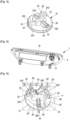
- Figure 1 illustrates a handle 1 for opening and/or closing a vehicle door according to the invention.
- the handle 1 for opening and/or closing a vehicle door 2 ( figure 13 ) comprises a cover member 4 configured to be secured to a bracket 6 ( figure 12 ).
- the cover member 4 comprises a frame part 8.
- the cover member 4 comprises an inner wall part 10 extending from the frame part 8.
- the cover member 4 comprises a cover element 16 configured to cover the opening 14.
- the cover element 16 is configured to be movable between a locked position ( figure 7 ) and an unlocked position ( figure 8 ), so that when in the unlocked position, the cover element 16 can be moved away from the opening 14, the cover element 16 being configured to be moved from the locked position ( figure 7 ) to the unlocked position ( figure 8 ) by rotating the cover element 16 with respect to the access part 12 according to the opening axis X.
- the opening axis refers to the mathematical axis around which the cover element 16 is configured to rotate with respect to the access part 12 to be moved from the locked position to the unlocked position.
- This opening mechanism also allows for reduced volume of the parts necessary to allow such access. Therefore, access to a device such as a backup device is made possible while the corresponding mechanical parts take limited space within the door handle.
- the access part 12 is an access part to a mechanical lockset (not shown) and the cover element 16 can be moved away from to the opening 14 such that the mechanical lockset can be accessed.
- the handle 1 comprises a gripping means 18 configured to be graspable by the user's hand to manually open the vehicle door.
- the gripping means 18 is arranged on the frame part 8 of the cover element 16.
- the gripping means 18 is a strip such as a chrome strip.
- the access part 12 is arranged on the inner wall part 10 of the cover member 4.
- the access part is the least visible on the handle, for instance from the user's side of the vehicle door, for instance a user's point of view from outside the vehicle when the handle is mounted on the vehicle door and the vehicle door 2 is mounted on the vehicle.
- the inner wall part 10 can for instance comprise a wall part and a guide part.
- the access part 12 is arranged on the wall part.
- the guide part forms a guide extending so as to allow access by a user's hand to at least one electronic switch of the bracket 6 as described hereafter.
- the guide part is for instance arranged sideways with respect to the guide part, for instance such that the wall part extends upstream a path of the guide part going downstream towards the electronic switch.
- the cover element 16 comprises at least one mounting and/or dismounting means 20, 20' and the access part comprises at least one complementary mounting and/or dismounting means 22, 22' disposed at the opening 14.
- the at least one mounting and/or dismounting means 20, 20' of the cover element 16 and the at least one complementary mounting and/or dismounting means 22, 22' of the access part 12 are configured to cooperate with each other in the locked position.
- the at least one mounting and/or dismounting means 20, 20' of the cover element 16 is a first part of a bayonet mounting and/or dismounting means and the at least one complementary mounting and/or dismounting means 22, 22' of the access part is a second part of a bayonet mounting and/or dismounting means.
- the at least one mounting and/or dismounting means 20, 20' of the cover element 16 is or comprises a lug or ridge 24, 24' or any other suitable element configured to ensure a rotation stop.
- the lug 24, 24' is arranged on a first side 26 of the cover element 16 and protrudes with respect to the first side 26 of the cover element 16.
- the first side 26 can for instance correspond to a side that is opposite to a second side accessible to the user.
- the first side 26 can be an inner side facing away from the outside of the vehicle door 2 when the vehicle door 2 is mounted on the vehicle.
- the opening 14 can for instance connect the first side and the second side.
- the opening axis X can for instance connect the first side and the second side.
- the lug 24, 24' comprises a first portion 240, 240' and a second portion 242, 242', tilted with respect to the first portion 240, 240'.
- the first portion 240, 240' can extend away from a central part of the cover element 16 from a central extremity to a peripheral extremity.
- the second portion 242, 242' can extend from the peripheral extremity of the first portion 240, 240'.
- the second portion 242, 242' extends from a proximal portion thereof, connected to the peripheral extremity, to an extremal portion thereof.
- second portion 242, 242' comprises a connecting portion connecting the proximal portion and the extremal portion.
- the central part of the cover element 16 may present a protrusion.
- the protrusion can be formed by a slot 44 as described hereunder, the slot 44 extending on the other side of the cover element 16.
- the first portion 240, 240' for instance the central extremities thereof, can extend from the protrusion.
- the protrusion have an elongated shape. The protrusion ensures that the slot 44 is closed, thus preventing dirt to enter that way.
- the at least one complementary mounting and/or dismounting means 22, 22' of the access part 12 can be or comprise a housing 28, 28' arranged on a wall 30, 30' of the cover member.
- the housing 28, 28' can be arranged at the level of opening 14, for instance around the opening 14.
- the housing 28, 28' can form an aperture, for instance an opening within the wall 30, 30', for instance an opening connecting the first side and the second side.
- the housing 28, 28' is configured to receive at least a portion of the lug 24, 24', for example at least a portion of the second portion 242, 242' of the lug 24, 24', for instance the extremal portion thereof, so that the lug 24, 24' ensures a rotation stop when received in the housing 28, 28', for example in the locked position.
- the connecting portion is for example thinner than the extremal portion and/or the extremal portion and the connecting portion are arranged so as to form a hook, for instance the extremal portion extending from the connecting portion so as to be directed back towards a face of the first side of the cover element and/or towards the second side of the cover element, for example facing away from the mechanical lockset.
- the cover element comprises two mounting and/or dismounting means 20, 20' and the access portion comprises two complementary mounting and/or dismounting means 22, 22' disposed at the opening 14.
- the cover element comprises a first mounting and/or dismounting means 20 and second mounting dismounting means 20' and the access part comprises a first complementary mounting and/or dismounting means 22 and a second complementary mounting and/or dismounting means 22', disposed at the opening 14.
- the first mounting and/or dismounting means 20 of the cover element and the first complementary mounting and/or dismounting means 22 of the access part cooperate with each other in the locked position
- the second mounting and/or dismounting means 20' of the cover element and the second complementary mounting and/or dismounting means 22' of the access part cooperate with each other in the locked position
- the mounting and/or dismounting means of the cover member and the complementary mounting and/or dismounting means of the access part cooperate with each other by clipping.
- the at least one lug 24, 24' comprises a recess 32 ( figure 4 ) configured to cooperate with the walls 30, 30' of the access part.
- the recess result in the connecting portion forms a bridge connecting the proximal portion and the extremal portion over a portion of the access part separating the opening 14 and the aperture of the housing 28, 28'.
- the cover member 4 comprises guiding means 34 configured to guide the cover element 16 when the cover element is moved to the locked position.
- the guiding means 34 comprises a guide rail 36 and a guide shoe 38, the access part 12 comprising the guide rail 36, and the cover element 16 comprising the guide shoe 38.
- the guide shoe 38 is configured to cooperate with the guide rail 36.
- the guide rail 36 is a third wall 30" disposed at the opening 14.
- the guide shoe 38 comprises an arm 380 arranged on a first side 26 of the cover element 16 and protrudes with respect to the first side of the cover element.
- the arm 380 comprises an end comprising a notch 40 ( figure 4 ) so that the arm 380 can cooperate with the third wall 30" of the guide rail.
- the access part 12 comprises a housing 42 arranged between two walls 30', 30"disposed at the opening. This housing 42 permits to guide the cover element with respect to the opening when the cover element is assembled to the opening to cover the opening.
- the cover element 16 comprises a slot 44 adapted for receiving a mechanical key such that the cover element 16 can be rotated between the locked position and unlocked position by the mechanical key.
- the cover element in the unlocked position, can be moved away from the opening by pulling and/or pushing the cover element, for instance with the help of a mechanical key inserted therein.
- the handle can be configured such that in the unlocked position, the cover element 16 is in an instable equilibrium position such that it tends to fall when solicited, for instance solicited by pulling and/or pushing, for instance with the help of a mechanical key inserted therein.
- the handle can be configured such that the cover element 16 is press fit with respect the cover member 4, for example the press fit being undone upon reaching the unlocked position, and/or by pulling and/or pushing the cover element 16, for instance with the help of a mechanical key inserted therein, thus resulting in the cover element 16 being moved away from the opening.
- the mechanical key once inserted, can cooperate with the slot so as to allow pulling of the cover element when pulling the key towards the user's side.
- the handle 1 comprises a connecting element 48 connecting the cover element 16 to another part of the cover member 4 so that the cover element 16 remains connected to the cover member 4 even when the cover element 16 is moved away from the opening 14 such that the mechanical lockset can be accessed.
- the connecting element allows easy retrieval of the cover element when it is not in the locked position.
- the connecting element allows the cover element to be moved with respect to the another part of the cover member while remaining at a predetermined maximum distance thereof.
- connecting element 48 does not prevent the cover element from being moved freely in translations and rotations with respect to the another part.
- the cover element 16 comprises a first retaining element 460 configured to retain a first portion of the connecting element 48
- the cover member 4 comprises a second retaining element 460' configured to retain a second portion of the connecting element 48, such that the cover element is linked to the cover member if the cover element is dismounted from the opening.
- the second retaining element 460' can form the another part of the cover member.
- the second retaining element 460' can for example extend from one of the clipping means 58, 58' described hereafter.
- the connecting element 48 can comprise or form a wire and/or a chain.
- the connecting element 48 connects the cover element 16 to another part of the cover member 4.
- the connecting element 48 comprises a first end secured to the first retaining element 460 of the cover element end a second end secured to the second retaining element 460'of the cover member.
- the first retaining element 460, and/or respectively the second retaining element 460', can have a hole for retaining the first portion of the connecting element48, and/or respectively the second portion of the connecting element 48.
- the first retaining element can extend from the central part of the cover element 16, for instance from the protrusion.
- the first retaining element can extend from the central extremity of the first portion 240'.
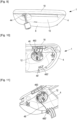
- Figure 12 illustrates an assembly for opening and/or closing according to the present invention.
- the assembly 100 comprises a bracket 6 configured to be assembled to an inner side of the vehicle door 2.
- the bracket 6 comprises at least one electronic switch configured to be activated by a user's touch to send a signal to an electronic latch to open the door.
- the assembly 100 comprises the handle as previously described.
- the bracket 6 is configured to be assembled to the inner side of the vehicle door 50.
- bracket 6 By “assembled to the inner side” it is to be understood that the bracket 6 can be fixed or attached or assembled by any suitable means to the inner side of the vehicle door 2.
- inner side of the door it is understood for example the side of the door destined to face the vehicle interior, by opposition to an outer side of the door destined to be disposed towards the exterior environment.
- the bracket is fixed to the inner side of the door 2 by means of screws 52, 52'.
- the bracket 6 is fixed to the inner side of the vehicle door by means a first screw 56 and second screw 56'.
- the bracket 56 is positioned against the inner side of the vehicle door.
- the bracket 6 comprises at least one electronic switch configured to be activated by a user's touch, for example, by mean of a user's finger touch.
- the electronic switch When activated by the user's touch, the electronic switch sends a signal to an electronic latch (not shown) so that the electronic latch open the vehicle door 2.
- the at least one switch is arranged on an upper part 6' of the bracket 6.
- the at least one switch is arranged behind a casing 54 arranged on the upper part 6' of the bracket 6.
- the cover member 4 is configured to be secured to the bracket 6.
- bracket 6 and the cover member 4 comprise complementary fastening means which cooperate with each other so that the cover member can be secured to the bracket.
- the cover member 4 comprises two clipping means 58, 58' and the bracket 6 comprises two corresponding housings 60, 60' ( figure14 ) each configured to receive one of the clipping means 58, 58' of the cover member 4.
- the assembly is configured such that the cover member 4 can be locked in position to the bracket 6.
- the bracket 6 can comprise a locking element.
- the locking element can be configured such that a sliding of the locking element with respect to a body of the bracket allows for locking the cover member on the bracket 6. The locking can result from the locking element being positioned at least partially between the clipped clipping means 58, 58' and the aperture.
- the cover member 48 is configured to be assembled to the external side of the vehicle door 2, opposite to the inner side of the door.
- the vehicle door 2 comprises an opening 62 ( figure 13 ) so that the cover member 4 can be assembled to the external side of the door and secured to the bracket 6.
- the frame part 8 is sized so that a user's hand can passes through the frame part 8.
- the frame part 8 is configured to be positioned against the external side of the vehicle door.
- the inner wall part 10 of the cover member 4 extends from the frame part 8.
- the inner wall part 10 extends from the frame part 8 so as to allow access by the user's hand the at least one electronic switch of the bracket when the handle is secured to the bracket.
- the inner wall part can form a guide to the at least one electronic switch.
- the inner wall part 10 can be tilted with respect to the frame part 8. This configuration permits to guide the user's hand toward the at least one electronic switch arranged on the upper part of the bracket 6.
- the inner wall part is curved ( figure 2 ).
- the frame part 8 and the tilted inner wall part 10 may form a bowl shape element.
- the frame part 10 and the tilted inner wall part may form a handle of the bowl type, for instance a bowl-shaped handle.
- the frame part 8 and the inner wall part 10 can be made integrally.
- the mechanical lockset is arranged on the bracket 6 (not visible).
- the opening 14 of the access part 12 allows an access to the mechanical lockset arranged on the bracket.
- the cover element 16 hide the opening 14.
- the user In case of electronic failure, the user remove the cover element 16 from the opening 14 of the access part 12 so that the mechanical lockset can be accessed.
- the vehicle door can be unlocked using a mechanical key inserted in the mechanical lockset.
- the user can pull on the strip 18 of the handle 1 to open the vehicle door manually.
- a system can comprise such an assembly 100 and the corresponding vehicle door.
- the assembly is assembled to the vehicle door.
- the assembly can further comprise the vehicle including the vehicle door mounted thereon.
- the system can comprise the mechanical lockset.
- the system can comprise the mechanical key configured to cooperate with the mechanical lockset and/or with the slot.
- a method for opening a vehicle door by means of the assembly as previously described comprises a step of moving the cover element 16 from the locked position to the unlocked position by rotating the cover element 16 with respect to the access part 12 according to the opening axis X.
- the method for opening further comprises a step of moving the cover element 16 in the unlocked position away from to the opening 14 such that the mechanical lockset can be accessed.
- the method for opening further comprises a step of accessing the mechanical lockset with the corresponding mechanical key and having the mechanical lockset and the mechanical key cooperate so as to open the door.
Landscapes
- Lock And Its Accessories (AREA)
Claims (12)
- Griff (1) zum Öffnen und/oder Schließen einer Fahrzeugtür, wobei der Griff (1) ein Abdeckbauteil (4) umfasst, das dazu konfiguriert ist, an einer Halterung befestigt zu werden, wobei das Abdeckbauteil (4) Folgendes umfasst:∘ ein Rahmenteil (8), und∘ ein Innenwandteil (10), das sich vom Rahmenteil (8) erstreckt, um zu ermöglichen, dass ein Benutzer mit der Hand auf mindestens einen elektronischen Schalter der Halterung zugreifen kann, wobei der mindestens eine elektronische Schalter dazu konfiguriert ist, durch Berührung eines Benutzers aktiviert zu werden, um ein Signal an einen elektronischen Riegel zu senden, um die Tür zu öffnen,wobei das Abdeckbauteil (4) Folgendes umfasst:∘ ein Zugangsteil (12) zu einem mechanischen Schloss, wobei das Zugangsteil (12) eine Öffnung (14) aufweist, durch die auf das mechanischen Schloss zugegriffen werden kann, wobei die Öffnung (14) eine durch die Öffnung verlaufende Öffnungsachse (X) definiert,∘ ein Abdeckelement (16), das dazu konfiguriert ist, die Öffnung (14) abzudecken,dadurch gekennzeichnet, dass das Abdeckelement (16) dazu konfiguriert ist, zwischen einer verriegelten Position und einer entriegelten Position bewegbar zu sein, so dass, wenn sich das Abdeckelement (16) in der entriegelten Position befindet, es von der Öffnung (14) derart wegbewegt werden kann, dass auf das mechanische Schloss zugegriffen werden kann, wobei das Abdeckelement (16) dazu konfiguriert ist, von der entriegelten Position in die entriegelte Position bewegt zu werden, indem das Abdeckelement (16) in Bezug auf das Zugangsteil (12) gemäß der Öffnungsachse (X) gedreht wird.
- Griff (1) nach Anspruch 1, wobei der Zugangsabschnitt (12) am Innenwandteil (10) des Abdeckbauteils (4) angeordnet ist.
- Griff (1) nach Anspruch 1 oder 2, wobei das Abdeckelement (16) mindestens ein Montage- und/oder Demontagemittel (20, 20') umfasst, und wobei das Zugangsteil (12) mindestens ein komplementäres Montage- und/oder Demontagemittel (22, 22') umfasst, das an der Öffnung (14) angeordnet ist, so dass das mindestens eine Montage- und/oder Demontagemittel (20, 20') des Abdeckelements (16) und das mindestens eine komplementäre Montage- und/oder Demontagemittel (22, 22') des Zugangsteils (12) in der verriegelten Position miteinander zusammenwirken.
- Griff (1) nach Anspruch 3, wobei das mindestens eine Montage- und/oder Demontagemittel (20, 20') ein erster Teil eines Bajonett-Montage- und/oder Demontagemittels (24, 24') ist, und wobei das mindestens zweite Montage- und/oder Demontagemittel (22, 22') ein zweiter Teil eines Bajonett-Montage- und/oder Demontagemittels (28, 28') ist.
- Griff (1) nach Anspruch 3 oder 4, wobei das mindestens eine Montage- und/oder Demontagemittel (20, 20') des Abdeckbauteils und das mindestens eine komplementäre Montage- und/oder Demontagemittel (22, 22') des Zugangsteils durch Verklipsen miteinander zusammenwirken.
- Griff (1) nach einem der vorhergehenden Ansprüche, wobei das Abdeckelement (16) einen Schlitz (44) umfasst, der zum Aufnehmen eines mechanischen Schlüssels ausgelegt ist, so dass das Abdeckelement durch den mechanischen Schlüssel zwischen der verriegelten Position und der entriegelten Position gedreht werden kann.
- Griff (1) nach einem der vorhergehenden Ansprüche, der ein Verbindungselement (48) umfasst, das das Abdeckelement mit einem anderen Teil des Abdeckbauteils verbindet, so dass das Abdeckelement auch dann mit dem Abdeckbauteil verbunden bleibt, wenn das Abdeckelement in Bezug zur Öffnung bewegt wird, so dass auf das mechanische Schloss zugegriffen werden kann.
- Griff (1) nach einem der vorhergehenden Ansprüche, wobei das Abdeckbauteil (16) Führungsmittel umfasst (die dazu konfiguriert sind, das Abdeckelement zu führen, wenn das Abdeckelement in die verriegelte Position bewegt wird.
- Griff nach dem vorhergehenden Anspruch, wobei die Führungsmittel (34) eine Führungsschiene (36) und einen Führungsschuh (38) umfassen, wobei das Zugangsteil die Führungsschiene (36) umfasst und das Abdeckelement den Führungsschuh (38) umfasst, wobei der Führungsschuh (38) dazu konfiguriert ist, mit der Führungsschiene (36) zusammenzuwirken.
- Anordnung (100) zum Öffnen und/oder Schließen einer Fahrzeugtür, wobei die Anordnung (100) Folgendes umfasst:- eine Halterung (6), die dazu konfiguriert ist, an einer Innenseite der Tür montiert zu werden, wobei die Halterung mindestens einen elektronischen Schalter umfasst, der dazu konfiguriert ist, durch Berührung eines Benutzers aktiviert zu werden, um ein Signal an einen elektronischen Riegel zu senden, um die Tür zu öffnen,- den Griff (1) nach einem der vorhergehenden Ansprüche.
- Verfahren zum Öffnen einer Fahrzeugtür mit Hilfe der Anordnung nach dem vorhergehenden Anspruch, wobei das Verfahren einen Schritt des Bewegens des Abdeckelements (16) von der verriegelten Position in die entriegelte Position durch Drehen des Abdeckelements (16) in Bezug auf das Zugangsteil (12) gemäß der Öffnungsachse (X) umfasst.
- Verfahren nach dem vorhergehenden Anspruch, das ferner den Schritt des Bewegens des Abdeckelements (16) in der entriegelten Position von der Öffnung (14) weg umfasst, so dass auf das mechanische Schloss zugegriffen werden kann.
Priority Applications (5)
| Application Number | Priority Date | Filing Date | Title |
|---|---|---|---|
| EP22150936.7A EP4209652B1 (de) | 2022-01-11 | 2022-01-11 | Griff zum öffnen und/oder schliessen einer fahrzeugtür |
| ES22150936T ES3002744T3 (en) | 2022-01-11 | 2022-01-11 | Handle for opening and/or closing a vehicle door |
| CN202380016811.8A CN118525125A (zh) | 2022-01-11 | 2023-01-10 | 用于打开和/或关闭车门的把手 |
| PCT/EP2023/050493 WO2023135149A1 (en) | 2022-01-11 | 2023-01-10 | Handle for opening and/or closing a vehicle door |
| US18/769,607 US20240368918A1 (en) | 2022-01-11 | 2024-07-11 | Handle for opening and/or closing a vehicle door |
Applications Claiming Priority (1)
| Application Number | Priority Date | Filing Date | Title |
|---|---|---|---|
| EP22150936.7A EP4209652B1 (de) | 2022-01-11 | 2022-01-11 | Griff zum öffnen und/oder schliessen einer fahrzeugtür |
Publications (2)
| Publication Number | Publication Date |
|---|---|
| EP4209652A1 EP4209652A1 (de) | 2023-07-12 |
| EP4209652B1 true EP4209652B1 (de) | 2024-10-02 |
Family
ID=79316809
Family Applications (1)
| Application Number | Title | Priority Date | Filing Date |
|---|---|---|---|
| EP22150936.7A Active EP4209652B1 (de) | 2022-01-11 | 2022-01-11 | Griff zum öffnen und/oder schliessen einer fahrzeugtür |
Country Status (5)
| Country | Link |
|---|---|
| US (1) | US20240368918A1 (de) |
| EP (1) | EP4209652B1 (de) |
| CN (1) | CN118525125A (de) |
| ES (1) | ES3002744T3 (de) |
| WO (1) | WO2023135149A1 (de) |
Family Cites Families (4)
| Publication number | Priority date | Publication date | Assignee | Title |
|---|---|---|---|---|
| DE102017124568A1 (de) * | 2017-10-20 | 2019-04-25 | Dr. Ing. H.C. F. Porsche Aktiengesellschaft | Türaußengriffanordnung für ein Kraftfahrzeug |
| DE102018100654A1 (de) * | 2018-01-12 | 2019-07-18 | Huf Hülsbeck & Fürst Gmbh & Co. Kg | Kraftfahrzeug-Griffanordnung und Verfahren zur Montage einer solchen Kraftfahrzeug-Griffanordnung |
| FR3081489B1 (fr) * | 2018-05-25 | 2022-09-09 | U Shin Italia Spa | Dispositif de poignee d’ouvrant, notamment pour vehicule |
| JP7218610B2 (ja) * | 2019-02-26 | 2023-02-07 | 株式会社アイシン | 車両用ドアハンドル装置 |
-
2022
- 2022-01-11 EP EP22150936.7A patent/EP4209652B1/de active Active
- 2022-01-11 ES ES22150936T patent/ES3002744T3/es active Active
-
2023
- 2023-01-10 CN CN202380016811.8A patent/CN118525125A/zh active Pending
- 2023-01-10 WO PCT/EP2023/050493 patent/WO2023135149A1/en not_active Ceased
-
2024
- 2024-07-11 US US18/769,607 patent/US20240368918A1/en active Pending
Also Published As
| Publication number | Publication date |
|---|---|
| CN118525125A (zh) | 2024-08-20 |
| US20240368918A1 (en) | 2024-11-07 |
| EP4209652A1 (de) | 2023-07-12 |
| WO2023135149A1 (en) | 2023-07-20 |
| ES3002744T3 (en) | 2025-03-07 |
Similar Documents
| Publication | Publication Date | Title |
|---|---|---|
| JP7419624B2 (ja) | 車両のドアパネル用ハンドル装置 | |
| JP4934074B2 (ja) | スイッチ固定構造 | |
| US7832240B2 (en) | Lid lock device | |
| US12258796B2 (en) | Door handle assembly having an outer bezel mechanism and an inner bracket mechanism | |
| US10712082B1 (en) | Refrigerator appliance with automatic open drawer front | |
| US20050011129A1 (en) | Closure system for motor vehicle motorized trunk | |
| WO2001046544A2 (en) | Vehicle lock assembly including a mounting bracket | |
| EP4209652B1 (de) | Griff zum öffnen und/oder schliessen einer fahrzeugtür | |
| US20020056299A1 (en) | Switchlock assembly with snap-in cam | |
| KR101956990B1 (ko) | 차량용 후드래치 어셈블리 | |
| US20230049181A1 (en) | Device for controlling external opening of an automobile vehicle door | |
| JP2006207192A (ja) | ドアラッチ装置 | |
| EP4209650A1 (de) | Vorrichtung zum öffnen und/oder schliessen einer fahrzeugtür | |
| JP4645324B2 (ja) | 車両用ドア | |
| EP4209651A1 (de) | Konsole zur montage an der innenseite einer fahrzeugtür und zugehörige anordnung und verfahren | |
| JP4641122B2 (ja) | 自動車用ドアロック組立体 | |
| EP0558211B1 (de) | Türverriegelung und Schlossaufbau | |
| KR101862511B1 (ko) | 잠금 기능을 갖춘 창호용 레버 | |
| US3433519A (en) | Automobile door internal handle assembly | |
| US20120119525A1 (en) | Method for assembling a handle in an openable body section of an automobile and associated openable body section handle | |
| CN219762959U (zh) | 展示柜 | |
| CN110644869A (zh) | 集成门闩锁组件、车辆以及操作车辆的滑动门的方法 | |
| JP2025071608A (ja) | 車両用ドア | |
| JPS5910282Y2 (ja) | 車両用ドアのインサイドハンドル機構 | |
| JPS597131Y2 (ja) | 自動車のバツクドア−構造 |
Legal Events
| Date | Code | Title | Description |
|---|---|---|---|
| PUAI | Public reference made under article 153(3) epc to a published international application that has entered the european phase |
Free format text: ORIGINAL CODE: 0009012 |
|
| STAA | Information on the status of an ep patent application or granted ep patent |
Free format text: STATUS: REQUEST FOR EXAMINATION WAS MADE |
|
| 17P | Request for examination filed |
Effective date: 20220111 |
|
| AK | Designated contracting states |
Kind code of ref document: A1 Designated state(s): AL AT BE BG CH CY CZ DE DK EE ES FI FR GB GR HR HU IE IS IT LI LT LU LV MC MK MT NL NO PL PT RO RS SE SI SK SM TR |
|
| RAP3 | Party data changed (applicant data changed or rights of an application transferred) |
Owner name: MINEBEA ACCESSSOLUTIONS ITALIA S.P.A. |
|
| RIN1 | Information on inventor provided before grant (corrected) |
Inventor name: CANNAVO, ANTONINO Inventor name: GUERIN, ANTHONY Inventor name: SAVANT, MARCO |
|
| GRAP | Despatch of communication of intention to grant a patent |
Free format text: ORIGINAL CODE: EPIDOSNIGR1 |
|
| STAA | Information on the status of an ep patent application or granted ep patent |
Free format text: STATUS: GRANT OF PATENT IS INTENDED |
|
| INTG | Intention to grant announced |
Effective date: 20240423 |
|
| GRAS | Grant fee paid |
Free format text: ORIGINAL CODE: EPIDOSNIGR3 |
|
| GRAA | (expected) grant |
Free format text: ORIGINAL CODE: 0009210 |
|
| STAA | Information on the status of an ep patent application or granted ep patent |
Free format text: STATUS: THE PATENT HAS BEEN GRANTED |
|
| AK | Designated contracting states |
Kind code of ref document: B1 Designated state(s): AL AT BE BG CH CY CZ DE DK EE ES FI FR GB GR HR HU IE IS IT LI LT LU LV MC MK MT NL NO PL PT RO RS SE SI SK SM TR |
|
| REG | Reference to a national code |
Ref country code: GB Ref legal event code: FG4D |
|
| REG | Reference to a national code |
Ref country code: CH Ref legal event code: EP |
|
| REG | Reference to a national code |
Ref country code: DE Ref legal event code: R096 Ref document number: 602022006436 Country of ref document: DE |
|
| REG | Reference to a national code |
Ref country code: IE Ref legal event code: FG4D |
|
| REG | Reference to a national code |
Ref country code: LT Ref legal event code: MG9D |
|
| REG | Reference to a national code |
Ref country code: NL Ref legal event code: MP Effective date: 20241002 |
|
| REG | Reference to a national code |
Ref country code: ES Ref legal event code: FG2A Ref document number: 3002744 Country of ref document: ES Kind code of ref document: T3 Effective date: 20250307 |
|
| REG | Reference to a national code |
Ref country code: AT Ref legal event code: MK05 Ref document number: 1728622 Country of ref document: AT Kind code of ref document: T Effective date: 20241002 |
|
| PG25 | Lapsed in a contracting state [announced via postgrant information from national office to epo] |
Ref country code: NL Free format text: LAPSE BECAUSE OF FAILURE TO SUBMIT A TRANSLATION OF THE DESCRIPTION OR TO PAY THE FEE WITHIN THE PRESCRIBED TIME-LIMIT Effective date: 20241002 |
|
| PG25 | Lapsed in a contracting state [announced via postgrant information from national office to epo] |
Ref country code: NL Free format text: LAPSE BECAUSE OF FAILURE TO SUBMIT A TRANSLATION OF THE DESCRIPTION OR TO PAY THE FEE WITHIN THE PRESCRIBED TIME-LIMIT Effective date: 20241002 |
|
| PG25 | Lapsed in a contracting state [announced via postgrant information from national office to epo] |
Ref country code: PT Free format text: LAPSE BECAUSE OF FAILURE TO SUBMIT A TRANSLATION OF THE DESCRIPTION OR TO PAY THE FEE WITHIN THE PRESCRIBED TIME-LIMIT Effective date: 20250203 Ref country code: HR Free format text: LAPSE BECAUSE OF FAILURE TO SUBMIT A TRANSLATION OF THE DESCRIPTION OR TO PAY THE FEE WITHIN THE PRESCRIBED TIME-LIMIT Effective date: 20241002 Ref country code: IS Free format text: LAPSE BECAUSE OF FAILURE TO SUBMIT A TRANSLATION OF THE DESCRIPTION OR TO PAY THE FEE WITHIN THE PRESCRIBED TIME-LIMIT Effective date: 20250202 |
|
| PG25 | Lapsed in a contracting state [announced via postgrant information from national office to epo] |
Ref country code: FI Free format text: LAPSE BECAUSE OF FAILURE TO SUBMIT A TRANSLATION OF THE DESCRIPTION OR TO PAY THE FEE WITHIN THE PRESCRIBED TIME-LIMIT Effective date: 20241002 |
|
| PG25 | Lapsed in a contracting state [announced via postgrant information from national office to epo] |
Ref country code: BG Free format text: LAPSE BECAUSE OF FAILURE TO SUBMIT A TRANSLATION OF THE DESCRIPTION OR TO PAY THE FEE WITHIN THE PRESCRIBED TIME-LIMIT Effective date: 20241002 |
|
| PG25 | Lapsed in a contracting state [announced via postgrant information from national office to epo] |
Ref country code: NO Free format text: LAPSE BECAUSE OF FAILURE TO SUBMIT A TRANSLATION OF THE DESCRIPTION OR TO PAY THE FEE WITHIN THE PRESCRIBED TIME-LIMIT Effective date: 20250102 |
|
| PG25 | Lapsed in a contracting state [announced via postgrant information from national office to epo] |
Ref country code: AT Free format text: LAPSE BECAUSE OF FAILURE TO SUBMIT A TRANSLATION OF THE DESCRIPTION OR TO PAY THE FEE WITHIN THE PRESCRIBED TIME-LIMIT Effective date: 20241002 Ref country code: LV Free format text: LAPSE BECAUSE OF FAILURE TO SUBMIT A TRANSLATION OF THE DESCRIPTION OR TO PAY THE FEE WITHIN THE PRESCRIBED TIME-LIMIT Effective date: 20241002 Ref country code: GR Free format text: LAPSE BECAUSE OF FAILURE TO SUBMIT A TRANSLATION OF THE DESCRIPTION OR TO PAY THE FEE WITHIN THE PRESCRIBED TIME-LIMIT Effective date: 20250103 |
|
| PG25 | Lapsed in a contracting state [announced via postgrant information from national office to epo] |
Ref country code: PL Free format text: LAPSE BECAUSE OF FAILURE TO SUBMIT A TRANSLATION OF THE DESCRIPTION OR TO PAY THE FEE WITHIN THE PRESCRIBED TIME-LIMIT Effective date: 20241002 Ref country code: CZ Free format text: LAPSE BECAUSE OF FAILURE TO SUBMIT A TRANSLATION OF THE DESCRIPTION OR TO PAY THE FEE WITHIN THE PRESCRIBED TIME-LIMIT Effective date: 20241002 |
|
| PG25 | Lapsed in a contracting state [announced via postgrant information from national office to epo] |
Ref country code: RS Free format text: LAPSE BECAUSE OF FAILURE TO SUBMIT A TRANSLATION OF THE DESCRIPTION OR TO PAY THE FEE WITHIN THE PRESCRIBED TIME-LIMIT Effective date: 20250102 |
|
| PG25 | Lapsed in a contracting state [announced via postgrant information from national office to epo] |
Ref country code: SM Free format text: LAPSE BECAUSE OF FAILURE TO SUBMIT A TRANSLATION OF THE DESCRIPTION OR TO PAY THE FEE WITHIN THE PRESCRIBED TIME-LIMIT Effective date: 20241002 |
|
| REG | Reference to a national code |
Ref country code: DE Ref legal event code: R097 Ref document number: 602022006436 Country of ref document: DE |
|
| PG25 | Lapsed in a contracting state [announced via postgrant information from national office to epo] |
Ref country code: DK Free format text: LAPSE BECAUSE OF FAILURE TO SUBMIT A TRANSLATION OF THE DESCRIPTION OR TO PAY THE FEE WITHIN THE PRESCRIBED TIME-LIMIT Effective date: 20241002 |
|
| PG25 | Lapsed in a contracting state [announced via postgrant information from national office to epo] |
Ref country code: EE Free format text: LAPSE BECAUSE OF FAILURE TO SUBMIT A TRANSLATION OF THE DESCRIPTION OR TO PAY THE FEE WITHIN THE PRESCRIBED TIME-LIMIT Effective date: 20241002 |
|
| PG25 | Lapsed in a contracting state [announced via postgrant information from national office to epo] |
Ref country code: RO Free format text: LAPSE BECAUSE OF FAILURE TO SUBMIT A TRANSLATION OF THE DESCRIPTION OR TO PAY THE FEE WITHIN THE PRESCRIBED TIME-LIMIT Effective date: 20241002 |
|
| PG25 | Lapsed in a contracting state [announced via postgrant information from national office to epo] |
Ref country code: SK Free format text: LAPSE BECAUSE OF FAILURE TO SUBMIT A TRANSLATION OF THE DESCRIPTION OR TO PAY THE FEE WITHIN THE PRESCRIBED TIME-LIMIT Effective date: 20241002 |
|
| PLBE | No opposition filed within time limit |
Free format text: ORIGINAL CODE: 0009261 |
|
| STAA | Information on the status of an ep patent application or granted ep patent |
Free format text: STATUS: NO OPPOSITION FILED WITHIN TIME LIMIT |
|
| REG | Reference to a national code |
Ref country code: CH Ref legal event code: PL |
|
| PG25 | Lapsed in a contracting state [announced via postgrant information from national office to epo] |
Ref country code: SE Free format text: LAPSE BECAUSE OF FAILURE TO SUBMIT A TRANSLATION OF THE DESCRIPTION OR TO PAY THE FEE WITHIN THE PRESCRIBED TIME-LIMIT Effective date: 20241002 |
|
| 26N | No opposition filed |
Effective date: 20250703 |
|
| PG25 | Lapsed in a contracting state [announced via postgrant information from national office to epo] |
Ref country code: LU Free format text: LAPSE BECAUSE OF NON-PAYMENT OF DUE FEES Effective date: 20250111 Ref country code: MC Free format text: LAPSE BECAUSE OF FAILURE TO SUBMIT A TRANSLATION OF THE DESCRIPTION OR TO PAY THE FEE WITHIN THE PRESCRIBED TIME-LIMIT Effective date: 20241002 |
|
| PG25 | Lapsed in a contracting state [announced via postgrant information from national office to epo] |
Ref country code: BE Free format text: LAPSE BECAUSE OF NON-PAYMENT OF DUE FEES Effective date: 20250131 |
|
| PG25 | Lapsed in a contracting state [announced via postgrant information from national office to epo] |
Ref country code: CH Free format text: LAPSE BECAUSE OF NON-PAYMENT OF DUE FEES Effective date: 20250131 |
|
| REG | Reference to a national code |
Ref country code: BE Ref legal event code: MM Effective date: 20250131 |
|
| PG25 | Lapsed in a contracting state [announced via postgrant information from national office to epo] |
Ref country code: IE Free format text: LAPSE BECAUSE OF NON-PAYMENT OF DUE FEES Effective date: 20250111 |
|
| PGFP | Annual fee paid to national office [announced via postgrant information from national office to epo] |
Ref country code: ES Payment date: 20260209 Year of fee payment: 5 |
|
| PGFP | Annual fee paid to national office [announced via postgrant information from national office to epo] |
Ref country code: DE Payment date: 20260114 Year of fee payment: 5 |
|
| PGFP | Annual fee paid to national office [announced via postgrant information from national office to epo] |
Ref country code: IT Payment date: 20260107 Year of fee payment: 5 |
|
| PGFP | Annual fee paid to national office [announced via postgrant information from national office to epo] |
Ref country code: FR Payment date: 20260128 Year of fee payment: 5 |