EP4204376B1 - Gehäuse zur bereitstellung einer kontrollierten umgebung während der herstellung von glasartikeln - Google Patents
Gehäuse zur bereitstellung einer kontrollierten umgebung während der herstellung von glasartikeln Download PDFInfo
- Publication number
- EP4204376B1 EP4204376B1 EP21762251.3A EP21762251A EP4204376B1 EP 4204376 B1 EP4204376 B1 EP 4204376B1 EP 21762251 A EP21762251 A EP 21762251A EP 4204376 B1 EP4204376 B1 EP 4204376B1
- Authority
- EP
- European Patent Office
- Prior art keywords
- enclosure
- inlet
- chamber
- width
- entry port
- Prior art date
- Legal status (The legal status is an assumption and is not a legal conclusion. Google has not performed a legal analysis and makes no representation as to the accuracy of the status listed.)
- Active
Links
Images


Classifications
-
- C—CHEMISTRY; METALLURGY
- C03—GLASS; MINERAL OR SLAG WOOL
- C03C—CHEMICAL COMPOSITION OF GLASSES, GLAZES OR VITREOUS ENAMELS; SURFACE TREATMENT OF GLASS; SURFACE TREATMENT OF FIBRES OR FILAMENTS MADE FROM GLASS, MINERALS OR SLAGS; JOINING GLASS TO GLASS OR OTHER MATERIALS
- C03C17/00—Surface treatment of glass, not in the form of fibres or filaments, by coating
- C03C17/001—General methods for coating; Devices therefor
-
- C—CHEMISTRY; METALLURGY
- C03—GLASS; MINERAL OR SLAG WOOL
- C03B—MANUFACTURE, SHAPING, OR SUPPLEMENTARY PROCESSES
- C03B17/00—Forming molten glass by flowing-out, pushing-out, extruding or drawing downwardly or laterally from forming slits or by overflowing over lips
- C03B17/04—Forming tubes or rods by drawing from stationary or rotating tools or from forming nozzles
-
- C—CHEMISTRY; METALLURGY
- C03—GLASS; MINERAL OR SLAG WOOL
- C03B—MANUFACTURE, SHAPING, OR SUPPLEMENTARY PROCESSES
- C03B23/00—Re-forming shaped glass
- C03B23/0073—Re-forming shaped glass by blowing
- C03B23/008—Vacuum-blowing
-
- C—CHEMISTRY; METALLURGY
- C03—GLASS; MINERAL OR SLAG WOOL
- C03C—CHEMICAL COMPOSITION OF GLASSES, GLAZES OR VITREOUS ENAMELS; SURFACE TREATMENT OF GLASS; SURFACE TREATMENT OF FIBRES OR FILAMENTS MADE FROM GLASS, MINERALS OR SLAGS; JOINING GLASS TO GLASS OR OTHER MATERIALS
- C03C17/00—Surface treatment of glass, not in the form of fibres or filaments, by coating
- C03C17/001—General methods for coating; Devices therefor
- C03C17/003—General methods for coating; Devices therefor for hollow ware, e.g. containers
- C03C17/005—Coating the outside
Definitions
- Embodiments of the present disclosure generally relate to controlled environments, and, more specifically, to controlled environments for use in the production of glass articles.
- Glass articles may be used in a variety of applications, including product packaging and specialty applications.
- the glass article may include a coating on the exterior of the glass article to impart a particular characteristic, such as to reduce or prevent scratches, to reflect UV light, or to impart a color on the surface of the glass.
- Coatings may be applied during the glass manufacturing process using any one of a variety of known techniques. For instance, US 3 895 126 and JP H10 67540 describe manufacturing lines for coating glass bottles. However, the performance of some techniques, such as spray coating techniques, often depends on the ambient environmental conditions in which the process occurs and in which the glass articles are located shortly after the process occurs. Moreover, vapors from solvents used in the coatings may evaporate from the surface of recently coated glass articles.
- Various embodiments provide enclosures that surround the glass articles and provide a controlled environment during at least part of the glass manufacturing process.
- the enclosures described herein can reduce the amount of temperature-and-humidity-controlled, filtered air required for the environment, and efficiently capture solvent evaporating from the glass articles, thereby preventing the solvent vapors from contaminating the ambient environment. Additionally, the enclosures of various embodiments can reduce or prevent contamination of the glass article from particles present in the ambient environment that may render the glass article unsuitable for its intended end use application.
- an enclosure for providing a controlled environment comprises a central plane extending through a top end of the enclosure and a bottom end of the enclosure and bisecting the enclosure along a width of the enclosure; an inlet at the bottom end of the enclosure having an inlet width, W inlet ; an enclosure wall extending from the inlet to the top end of the enclosure; an entry port at the top end of the enclosure configured to receive a part carrier; and an outlet between the entry port and the chamber region of the enclosure wall.
- the enclosure wall comprises a chamber region and a transition region between the inlet and the chamber region. The width of the chamber region, W chamber , is substantially constant through the chamber region.
- the width of the enclosure in the transition region decreases from W chamber to W inlet , and a ratio of W inlet to W chamber is from 1:2 to 1:5.
- the central plane passes through the inlet and the entry port of the enclosure, and the outlet extends along an outlet axis that is oriented at a non-zero angle with respect to the central plane.
- a manufacturing line for producing glass articles comprises an enclosure, and a part carrier.
- the enclosure comprises a central plane extending through a top end of the enclosure and a bottom end of the enclosure and bisecting the enclosure along a width of the enclosure; an inlet at the bottom end of the enclosure having an inlet width, W inlet ; an enclosure wall extending from the inlet to the top end of the enclosure; an entry port at the top end of the enclosure configured to receive a part carrier; and an outlet between the entry port and the chamber region of the enclosure wall.
- the enclosure wall comprises a chamber region and a transition region between the inlet and the chamber region. The width of the chamber region, W chamber , is substantially constant through the chamber region.
- the width of the enclosure in the transition region decreases from W chamber to W inlet , and a ratio of W inlet to W chamber is from 1:2 to 1:5.
- the central plane passes through the inlet and the entry port of the enclosure and the outlet extends along an outlet axis oriented at a non-zero angle with respect to the central plane.
- a gripping member of the part carrier is positioned through the entry port and the part carrier is configured to move a glass article through the chamber region of the enclosure.
- a method for transporting a coated article comprises positioning the coated article within an enclosure; supplying a flow of fluid to the enclosure through the inlet; removing a flow of fluid from the enclosure through the outlet; and moving the coated article along a path through the enclosure, where the path is substantially parallel to the central plane.
- the enclosure comprises a central plane extending through a top end of the enclosure and a bottom end of the enclosure and bisecting the enclosure along a width of the enclosure; an inlet at the bottom end of the enclosure having an inlet width, W inlet ; an enclosure wall extending from the inlet to the top end of the enclosure; an entry port at the top end of the enclosure configured to receive a part carrier; and an outlet between the entry port and the chamber region of the enclosure wall.
- the enclosure wall comprises a chamber region and a transition region between the inlet and the chamber region.
- a width of the chamber region, W chamber is substantially constant through the chamber region.
- the width of the enclosure in the transition region decreases from W chamber to W inlet , and a ratio of W inlet to W chamber is from 1:2 to 1:5.
- the central plane passes through the inlet and the entry port of the enclosure and the outlet extends along an outlet axis oriented at a non-zero angle with respect to the central plane.
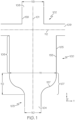
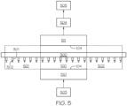
- FIG. 1 One embodiment of an enclosure is schematically depicted in FIG. 1 .
- the enclosure generally includes an enclosure wall, an inlet at the bottom end of the enclosure, a transition region, a chamber region, an entry port at the top of the enclosure and an outlet between the entry port and the chamber region.
- a central plane passes through the top end and the bottom end of the enclosure and bisects the enclosure along a width of the enclosure.
- controlled environment refers to an enclosed or partially enclosed volume in which certain atmospheric conditions are maintained within set boundaries. For example, temperature, pressure, and humidity may be kept within specified ranges within a controlled environment. Additionally, the entrance of particles into the controlled environment may be regulated, for example, by filtration of incoming air.
- laminar flow refers to the flow of a fluid including, without limitation, air that is free from cross-currents, eddies, swirls, and lateral mixing.
- an "inflection point” refers to a point along a curve where the curve transitions from concave to convex or from convex to concave.
- reflection symmetry refers to symmetry of an object with respect to a plane wherein the reflection of the object along that plane is indistinguishable from the object itself.
- FIG. 1 depicts an embodiment of an enclosure 100 for providing a controlled environment along at least a portion of, for example, a glass manufacturing line for producing coated glass articles.
- FIG. 1 schematically depicts a cross-section of the enclosure 100 along an XY plane as defined by the coordinate axes included in FIG. 1 .
- a central plane 101 provides a reference for several aspects of the enclosure 100. Specifically, the central plane 101 provides a reference for defining the symmetry of the enclosure 100, a position of an inlet 104 and an entry port 108 of the enclosure 100, and an orientation of an outlet 109 of the enclosure 100.
- the central plane 101 extends through a top end 102 and a bottom end 103 of the enclosure 100 in the +/-X direction.
- the central plane 101 extends in the Z direction through the length of the enclosure.
- the central plane 101 bisects the enclosure 100 along a width of the enclosure, for example, along a width of the inlet (W inlet 110), a width of a chamber region (W chamber 111), or a width of an entry (W entry 113).
- the enclosure 100 includes at least one enclosure wall 105, which extends from the bottom end 103 of the enclosure 100 to the top end 102 of the enclosure 100 and defines various regions of the enclosure 100.
- the enclosure wall 105 defines a chamber region 106 and a transition region 107 of the enclosure 100.
- the enclosure 100 includes two enclosure walls that oppose one another.
- the enclosure 100 may include enclosure walls on opposite sides of the central plane 101.
- the enclosure wall 105 includes one or more apertures through the enclosure wall 105.
- apertures through the enclosure wall 105 can include the inlet 104 and the outlet 109 of the enclosure 100.
- the enclosure wall 105 may comprise any material that is sufficiently smooth to facilitate laminar flow of air through the enclosure.
- the enclosure wall 105 may be formed from an opaque material, such as sheet metal or other, similar materials.
- a transparent material such as a polymer or plastic resin (e.g., PLEXIGLAS TM available from Arkema) may form the enclosure wall 105 to allow visual inspection of the various regions of the enclosure 100, including the chamber region 106 and the transition region 107.
- the enclosure wall 105 may be formed from a combination of opaque and transparent materials, such that at least a portion of the enclosure's interior may be visible from outside the enclosure 100. For example, in such embodiments, at least a portion of the chamber region 106 or the transition region 107, or both may be visible from the exterior of the enclosure 100.
- the inlet 104 is located at the bottom end 103 of the enclosure 100.
- the inlet 104 is an opening in the enclosure wall 105 that allows air to enter the enclosure 100.
- the inlet 104 may be formed between two opposing enclosure walls instead of being formed through a single enclosure wall.
- the inlet 104 has a width, W inlet 110.
- the width is measured in the Y direction from the inner surface 155 of the enclosure wall 105 to an opposing inner enclosure wall surface (e.g., the width is an interior width of the inlet 104).
- W inlet 110 is greater than or equal to 4 mm and less than or equal to 45 mm.
- W inlet 110 may be from 4 mm to 45 mm, from 4 mm to 40 mm, from 4 mm to 35 mm, from 4 mm to 30 mm, from 4 mm to 25 mm, from 4 mm to 20 mm, from 4 mm to 15 mm, from 4 mm to 10 mm, from 10 mm to 45 mm, from 15 mm to 45 mm, from 20 mm to 45 mm, from 25 mm to 45 mm, from 30 mm to 45 mm, from 35 mm to 45 mm, or even from 40 to 45 mm.
- the central plane 101 passes through the inlet 104 and bisects W inlet . In such embodiments, W inlet 110 is measured normal to the central plane 101.
- W inlet corresponds to the minimum interior width of the inlet 104.
- the enclosure wall 105 of the enclosure 100 defines a chamber region 106.
- the enclosure wall 105 extends in the X and Z directions through the chamber region 106 and is substantially parallel to the central plane 101 through the chamber region 106.
- the chamber region 106 has a width, W chamber 111.
- the width is measured in the Y direction from the inner surface 155 of the enclosure wall 105 to an opposing inner surface 155 of the enclosure wall 105 (e.g., the width is an interior width of the chamber region 106).
- W chamber 111 is substantially constant throughout the chamber region 106. In embodiments, W chamber 111 is greater than or equal to 20 mm and less than or equal to 90 mm.
- W chamber 111 may be from 20 mm to 90 mm, from 30 mm to 90 mm, from 40 mm to 90 mm, from 50 mm to 90 mm, from 60 mm to 90 mm, from 70 mm to 90 mm, or even from 80 mm to 90 mm.
- W chamber 111 may be from 20 mm to 80 mm, from 20 mm to 70 mm, from 20 mm to 60 mm, from 20 mm to 50 mm, from 20 mm to 40 mm, or even from 20 mm to 30 mm.
- Other values for the width 111 of the chamber region 106 are possible, provided that the width 111 is large enough to allow for adequate airflow around the maximum diameter of the part being transported through the enclosure 100.
- W chamber 111 is from 2 to 3 times the maximum diameter of the part. Additionally, in embodiments, the central plane 101 passes through the chamber region 106 of the enclosure 100 and bisects W chamber 111. In such embodiments, W chamber 111 is measured normal to the central plane 101.
- the enclosure 100 further comprises a transition region 107 between the inlet 104 and the chamber region 106.
- the transition region 107 is enclosed by a section of the enclosure wall 105 that is not parallel to the central plane 101.
- the width (e.g., the interior width) of the enclosure 100 decreases from W chamber 111 to W inlet 104.
- the decrease in width of the enclosure 100 takes place over a distance 112 (e.g., measured in the +/-X direction in FIG. 1 ) parallel to the central plane 101.
- the distance 112 is greater than or equal to 200 mm and less than or equal to 900 mm.
- the distance 112 may be from 200 mm to 900 mm, from 300 mm to 900 mm, from 400 mm to 900 mm, from 500 mm to 900 mm, from 600 mm to 900 mm, from 700 mm to 900 mm, or even from 800 mm to 900 mm.
- the distance 112 may be from 200 mm to 800 mm, from 200 mm to 700 mm, from 200 mm to 600 mm, from 200 mm to 500 mm, form 200 mm to 400 mm, or even from 200 mm to 300 mm.
- the distance 112 may be about ten times larger than W chamber 111.
- the ratio of W inlet 110 to W chamber 111 is from 1:2 to 1:5 or from 1:3 to 1:4.
- a transition region 107 dimensioned as described above i.e., where the ratio of W inlet 110 to W chamber 111 is from 1:2 to 1:5 may facilitate laminar air flow through the enclosure 100 by ensuring that the change in width of the enclosure 100 is not so sudden that eddies or other turbulent flow patterns are present in the air flowing from the inlet 104 into the chamber region 106.
- the flow through the transition region 107 may include transitional or turbulent flow, although the flow of fluid at both the chamber-end and the inlet end of the transition region 107 is one-dimensional.
- the enclosure wall 105 has an S-shaped curve within the transition region 107 of the enclosure 100, as illustrated in FIG. 1 .
- the S-shaped curve comprises an inflection point 157 at which a change in a direction of the curvature occurs.
- an S-shaped curve in the transition region 107 may help facilitate laminar air flow through the enclosure 100 by providing a smooth transition from the inlet 104 to the chamber region 106 of the enclosure 100.
- an S-shaped curve is specifically shown and described herein, it should be understood that other smooth curves and transitional shapes are possible and contemplated, provided they do not cause air flowing through the enclosure 100 to recirculate or become turbulent upon entry into the chamber region 106.
- the transition region 107 can be linear given a large enough distance 112 to enable one-dimensional fluid flow to be preserved without backflow.
- the enclosure 100 also comprises an entry port 108 at the top of the enclosure 100 that is configured to receive a part carrier (not shown in FIG. 1 ).
- the entry port 108 can be, for example an opening or slot through which the part is conveyed.
- the entry port 108 has a width, W entry 113, measured in the Y direction from an inner surface 158 of the entry port 108 to an opposing inner surface 158 of the entry port 108.
- W entry 113 is contingent on the dimensions of the part carrier.
- W entry 113 is greater than or equal to 1.0 cm and less than or equal to 5.0 cm.
- W entry 113 may be from 1.0 cm to 5.0 cm, from 1.5 cm to 5.0 cm, from 2.0 cm to 5.0 cm, from 2.5 cm to 5.0 cm, from 3.0 cm to 5.0 cm, from 3.5 cm to 5.0 cm, from 4.0 cm to 5.0 cm, or even from 4.5 cm to 5.0 cm.
- W entry 113 may be from 1.0 cm to 4.5 cm, from 1.0 cm to 4.0 cm, from 1.0 cm to 3.5 cm, from 1.0 cm to 3.0 cm, from 1.0 cm to 2.5 cm, from 1.0 cm to 2.0 cm, or even from 1.0 cm to 1.5 cm.
- W entry 113 is less than W chamber 111.
- the central plane 101 passes through the entry port 108 and, in embodiments, bisects the entry port 108 along W entry 113. In such embodiments, W entry 113 is measured normal to the central plane.
- the enclosure 100 further comprises at least one outlet 109 positioned between the entry port 108 and the chamber region 106 of the enclosure 100.
- the width of the outlet 109 is from 0.5 cm to 3.0 cm.
- the width of outlet 109 may be from 0.5 cm to 3.0 cm, from 1.0 cm to 3.0 cm, from 1.5 cm to 3.0 cm, from 2.0 cm to 3.0 cm, or even from 2.5 cm to 3.0 cm.
- the width of outlet 109 may be from 0.5 cm to 2.5 cm, from 0.5 cm to 2.0 cm, from 0.5 cm to 1.5 cm, or even from 0.5 cm to 1.0 cm.
- the outlet 109 extends along an outlet axis 112.
- the outlet axis 112 is oriented at a non-zero angle with respect to the central plane 101.
- the outlet axis 112 may be normal with respect to the central plane 101.
- the outlet axis 112 extends from the central plane 101 in the +/-Y direction and lies within a YZ plane.
- the enclosure 100 may comprise two outlets 109 where the outlets 109 are on opposite sides of the central plane 101 and the outlets 109 extend away from the central plane 101 along the outlet axis 112.
- each wall can include an outlet 109, with the outlets being symmetrically situated.
- the outlet 109 can be a single channel running along the length of the wall.
- the enclosure 100 comprises reflection symmetry with respect to the central plane 101. Without wishing to be bound by theory, it is believed that the symmetry of the enclosure 100 may facilitate a symmetric airflow pattern through the enclosure 100, which, in turn, may facilitate smooth, or laminar, airflow through the enclosure 100.
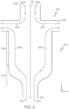
- fluid flow through the enclosure 100 is shown.
- the fluid flow is generally represented by flow lines 201-204. It should be understood that the flow lines 201-204 depict exemplary paths that fluid, such as air, may take through the enclosure 100 and that the flow of fluid is not limited specifically to the flow lines 201-204 in embodiments described herein.
- the fluid is supplied to the inlet 104 at a predetermined temperature and humidity from a fluid source, such as fluid source 503 ( FIG. 5 ).
- the fluid has a temperature of greater than or equal to 20 °C and less than or equal to 25 °C and a relative humidity (RH) of less than 60%.
- RH relative humidity
- the fluid may be supplied at a temperature from 20 °C to 25 °C, from 21 °C to 25 °C, from 22 °C to 25 °C, from 23 °C to 25 °C, or even from 24 °C to 25 °C.
- the temperature is measured by any suitable means, for example, by thermometer, thermography, or the like.
- the fluid may be supplied at a RH of less than 60%, less than 55%, less than 50%, less than 45%, or even less than 40%.
- RH is measured by any suitable means, for example, by hygrometer.
- the fluid supplied to the enclosure 100 is filtered before entering the enclosure 100.
- This can be achieved by passing the fluid through a high efficiency particulate air (“HEPA") filter before the fluid is provided to the inlet 104.
- HEPA high efficiency particulate air
- Any suitable HEPA filtration system known in the art may be used to filter the fluid entering the enclosure 100.
- filters other than HEPA filters can be used, depending on the particular embodiment. Without being bound by theory, it is believed that passing the fluid through a HEPA filter may remove particles from the fluid which could interfere with the coating on glass articles within the enclosure. Thus, filtering the fluid before it enters the enclosure may lead to an increased coating quality on the glass articles.
- passing the fluid entering the enclosure through a HEPA filter may remove particles that would contaminate the glass articles from entering the enclosure.
- filtering the fluid before it enters the enclosure may ensure that the glass articles are free from contaminants and suitable for use in, for example, pharmaceutical applications.
- fluid flow through the transition region 107 is substantially laminar (i.e., without eddies or other turbulent flow patterns).
- the fluid passing from the inlet 104 through the transition region 107 moves toward the top end 102 of the enclosure 100 (e.g., in the +X direction), regardless of its motion in the Y and Z directions.
- the fluid flow through the transition region 107 is free from eddies or currents in which the air flows toward the bottom end 103 of the enclosure 100 (e.g., in the -X direction).
- the flow lines 202 depicted in FIG. 2 depict the flow of fluid through the chamber region 106 of the enclosure 100. As in the transition region 107, the flow of fluid through the chamber region 106 is substantially laminar. As depicted by flow lines 202, the fluid continues to move toward the top end 102 of the enclosure 100 (e.g., in the +X direction) until it reaches the outlet 109. Once the fluid reaches the outlet 109, the fluid flows through the outlet 109 and is removed from the enclosure 100. To assist in maintaining the flow of fluid in the +X direction from the inlet 104 to the outlet 109, in embodiments, a vacuum is applied to the outlet 109 to establish a pressure differential through the enclosure 100, as will be discussed in greater detail herein.
- the fluid flow through the enclosure 100 is symmetric about the central plane 101.
- a glass article 302 such as a glass vial
- the symmetric fluid flow uniformly engulfs the surfaces of the glass article 302 with conditioned fluid that enters the enclosure through the inlet 104, which may ensure that the glass article 302 is protected from ambient air that could contain particles that could disrupt the coating or contaminate the glass article 302.
- the introduction of fluid into and through the enclosure 100 both flushes the volume of the enclosure of ambient air as well as supplies the interior volume of the enclosure with conditioned fluid (i.e., fluid having a desired temperature and/or relative humidity) which assists in uniformly processing a coating applied to the glass article.
- conditioned fluid i.e., fluid having a desired temperature and/or relative humidity
- the glass article 302 may be a pharmaceutical container, such as a vial or syringe; however, the glass article 302 is not limited to such containers.
- the ambient air entering the enclosure 100 through the entry port 108 may enter the enclosure 100 through the entry port 108 along flow lines 203.
- the ambient air entering the enclosure 100 through the entry port 108 is not temperature-or humidity-controlled or filtered to remove particulates. Accordingly, in embodiments, the position of the outlet 109 near the top end 102 of the enclosure 100 mitigates the flow of ambient air into the chamber region 106 through the entry port 108. As depicted by the flow lines 204, the ambient air exits the enclosure 100 through the outlet 109 before it is able to proceed into the chamber region 106.
- the outlet 109 is fluidly coupled to a vacuum source (e.g., vacuum source 504 in FIG. 5 ), which assists in maintaining the flow of fluid through the enclosure 100 as described above.
- a vacuum source e.g., vacuum source 504 in FIG. 5
- the vacuum can help to ensure that the ambient air exits the enclosure 100 before entering the chamber region 106 and that the fluid supplied through the inlet 104 constantly moves toward the top end 102 of the enclosure 100.
- the vacuum may induce pressures within the enclosure 100 below ambient pressure, which, in embodiments, ensures that any solvent evaporating from the coatings on the glass articles within the enclosure 100 exits through the outlet 109, as further discussed herein.
- Pressure within the enclosure 100 can be maintained at a pressure below ambient air pressure by controlling the vacuum fluidly coupled to the outlet 109 as well as the flow rate of fluid supplied to the enclosure 100 through the inlet 104, so the flow rate of fluid supplied to the enclosure 100 through the inlet 104 is less than or equal to the flow rate of fluid exiting the enclosure 100 through the outlet 109. Accordingly, an aggregate flow of fluid through the outlet 109 is greater than the flow of fluid entering the enclosure through the inlets to maintain a negative pressure within the chamber region 106. Any suitable method for controlling the flow rate of fluid known and used in the art can be used to ensure that the pressure within the enclosure 100 is maintained below ambient air pressure, such as a vacuum pump.
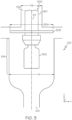
- the glass article 302 is coupled to a part carrier 300 through a gripping member 301 configured to move the glass article 302 along a manufacturing line through the enclosure 100.
- the gripping member 301 of the part carrier 300 extends through the entry port 108 of the enclosure 100 and holds the glass article 302 within the chamber region 106 of the enclosure 100.
- Suitable gripping members and part carriers are further described in U.S. Patent No. 10,576,494.
- the part carrier 300 moves the glass article 302 through the chamber region 106 of the enclosure 100 along a manufacturing line path (e.g., in the +Z direction), as depicted in FIGS. 3 and 4 .
- the part carrier 300 moves the glass article 302 through the chamber region 106 along the central plane 101.
- the glass article 302 may be situated within the enclosure 100 such that the central plane 101 generally bisects the glass article.
- the part carrier 300 comprises a plate 303 positioned between the entry port 108 and the chamber region 106 of the enclosure 100.
- the gripping member 301 is attached to the plate 303 so the plate 303 moves with the gripping member 301 through the enclosure 100.
- the plate 303 may be oriented such that a surface of the plate adjacent the entry port 108 lies in a plane normal to the central plane 101.
- the plate 303 has a width, W plate 304.
- W plate 304 refers to a maximum distance between two points on the edge of the plate 303 when measured across the plate 303 (as opposed to around the perimeter of the plate 303).
- W plate 304 is greater than or equal to W chamber 111.
- W plate 304 is greater than or equal to W entry 113.
- the plate 303 ensures that there is no direct, linear path between the entry port 108 and the glass article 302. Accordingly, the plate 303 can deflect ambient air entering from the entry port 108 toward the outlet 109. Additionally, any particles that enter the enclosure 100 through the entry port 108 can be intercepted by the plate 303 and prevented from contacting the glass articles 302.
- W plate 304 may be greater than W entry 113 and less than W chamber 111.
- the plate 303 may be in the form of a circular disk, although other shapes are contemplated.
- W plate corresponds to a diameter of the plate 303.
- a circular disk can advantageously uniformly direct the path of ambient air from the entry port 108 away from the glass article 302 being conveyed through the enclosure 100.
- the gripping member 301 rotates within the enclosure 100 (e.g., about an axis extending in the +/-X direction in the FIGS)
- the use of a circular disk maintains a constant relationship between Wpiate and W chamber or W entry at any point during the rotation of the gripping member 301.
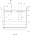
- FIG. 4 schematically depicts a side view of the enclosure 100 depicted in FIG. 3 to better illustrate the central plane 101 and the part carrier 300.
- the part carrier 300 forms part of a manufacturing line for producing glass articles 302.
- the central plane 101 is an XZ plane and extends through the inlet 104 at the bottom end 103 of the enclosure 100 and through the entry port 108 at the top end 102 of the enclosure 100. Additionally, the central plane 101 extends along a length of the enclosure 100, where the length of the enclosure is measured in the +/-Z direction.
- the part carrier 300 includes a plurality of gripping members 301 that may be conveyed through the enclosure 100.
- Each of the gripping members 301 is coupled to and moves a corresponding glass article 302 through the chamber region 106 of the enclosure 100.
- the gripping members 301 move along a length of the enclosure 100 in series along the manufacturing line path.
- the gripping members 301 move the glass articles 302 through the chamber region 106 along the central plane 101.
- the part carrier 300 is positioned to facilitate movement of the glass articles 302 from a coating apparatus 501, where a coating is applied to the glass articles 302, through the enclosure 100, and to a curing apparatus 502, where the coating is cured on the surface of the glass articles 302.
- a coating apparatus 501 where a coating is applied to the glass articles 302, through the enclosure 100, and to a curing apparatus 502, where the coating is cured on the surface of the glass articles 302.
- Other locations of the part carrier 300 (and the enclosure 100) within a glass article manufacturing line are contemplated and possible, depending on the particular embodiment.
- the gripping member 301 of the part carrier 300 can be replaced with a different interface for engaging the glass article 302, such as a platform on which the glass article 302 is positioned, a suction apparatus, or the like.
- the gripping member 301 of the part carrier 300 engages a glass article 302, such as by a vacuum chuck or closing robotic fingers around a neck region of the glass article 302.
- the glass article 302 can be engaged, for example, in a coating apparatus 501 or upstream of the coating apparatus 501 (e.g., prior to the glass article 302 entering the coating apparatus 501) as the glass article 302 moves along a glass article manufacturing line.
- the gripping member 301 moves along the manufacturing line path and enters the enclosure 100, thereby traversing a glass article 302 into and through the enclosure 100.
- the enclosure 100 can include an open end (not shown) that enables the glass article 302 to be passed between enclosure walls 105 of the enclosure 100 such that the glass article 302 is positioned within the chamber region 106 and the gripping member 301 extends through the entry port 108.
- a fluid knife such as an air knife or the like, may be positioned along the open end to prevent entry of particles and ambient air into the enclosure 100.
- the entry port 108 can include a region near the end of the enclosure 100 that has a width that is wider than the glass article 302 and the part carrier 300 (including the gripping member 301 and the plate 303).
- the part carrier 300 can vertically lower the glass article 302 (e.g., move the glass article 302 in the +/X direction) into the chamber region 106 of the enclosure 100 through the entry port 108 as it moves the glass article 302 along the manufacturing line path (e.g., along the +/-Z direction).
- conditioned fluid enters the enclosure 100 through the inlet 104 from a fluid source 503, which, in embodiments, is coupled to the inlet 104 by a manifold 510.
- the manifold 510 may include baffles or perforated plates to facilitate uniform fluid flow through the inlet 104.
- the fluid is conditioned to have a predetermined temperature, humidity, and particulate level, which can be achieved through various heating, humidity, and filtration systems.
- the conditioned fluid is provided to the inlet 104 at a predetermined flow rate and pressure, and flows through the enclosure 100 to the outlet 109, as was previously described with reference to FIG. 2 .
- a vacuum source 504 is additionally applied to the outlet 109 of the enclosure 100. Accordingly, a vacuum pump or other vacuum source 504 can be fluidly coupled to the outlet 109 by a manifold 511 to pull fluid from the enclosure 100 through the outlet 109.
- the vacuum source 504 in embodiments, further establishes a negative pressure within the enclosure 100, as described above, to facilitate flow of the conditioned fluid from the bottom end 103 of the enclosure 100 toward the top end 102 of the enclosure 100 and through the outlet 109.
- the part carrier 300 moves the glass articles 302 through the enclosure 100 along the manufacturing line path and, in embodiments, may further rotate the glass articles 302 around a rotation axis extending in the +/-X direction through the center of the glass article 302 and lying in the central plane 101.
- the part carrier 300 and more particularly, the gripping member 301, rotate the glass articles 302 at a rate of from 1000 to 3000 rotations per minute (RPM).
- the glass article 302 when the glass article 302 enters the enclosure 100, the glass article 302 has a coating thereon that includes one or more solvents.
- This solvent may evaporate from the surface of the glass article 302 while the coated glass article 302 is moving through the enclosure 100, thereby forming solvent vapors within the enclosure 100.
- the solvent vapors may be released from the surface of the glass article 302 during a partial curing of the coating as a result of the temperature and/or humidity of the environment within the enclosure 100.
- the solvent vapors are flushed from the enclosure 100 by the fluid and exit the enclosure 100 through the outlet 109.
- Negative pressure within the enclosure 100 ensures that nearly all the fluid within the enclosure 100 exits the enclosure 100 through the outlet 109, allowing the solvent to be removed from the fluid before the fluid is released into the environment.
- fluid including the solvent vapors are directed from the outlet 109, through the manifold 511 and the vacuum source 504, and to a solvent recovery system 505 or an air remediation system that filters, adsorbs, or otherwise separates the solvent vapors from the fluid flowing through the outlet 109 before the fluid is released into the ambient environment or recycled.
- solvent capture may reduce the presence of solvent in the ambient environment and also facilitate reclamation and recycling of the fluid and solvent.
- the enclosure 100 may be temperature controlled such that the enclosure 100 may act as a curing chamber. In such embodiments, the temperature within the enclosure is kept above 300 °C or higher, depending on the curing temperature of the coating. Accordingly, in embodiments, the air entering the enclosure 100 is heated. For example, heaters on the outside of metal pathways supplying air to the enclosure 100 may bring the temperature of the air entering the enclosure above 300 °C. Alternatively, the air may be passed through a heating unit to bring the air to the desired temperature. Using the enclosure 100 as a curing chamber may prevent particles from sticking to a coating on the glass article before the coating is cured. Additionally or alternatively, in embodiments, the enclosure 100 is temperature controlled to control solvent flash-off. In such embodiments, the temperature of the enclosure 100 is limited by the flammability limit of solvent of the coating on the glass article 302, but generally ranges from 60 °C to 100 °C.
- the part carrier 300 continues to move the glass articles 302 along the manufacturing line path until it reaches the next manufacturing station or location, which, in embodiments, may be a curing apparatus 502.
- the coating on each of the glass articles 302 is cured within the enclosure 100, or the glass articles 302 may exit the enclosure 100 before being directed into the curing apparatus 502.
- the curing apparatus 502 can be positioned within the enclosure 100 or adjacent to the enclosure 100, depending on the particular embodiment.
- the curing apparatus 502 may be any suitable type of curing apparatus, depending on the particular coating applied to the glass article 302.
- the curing apparatus 502 may be an oven or a light source (e.g., an infrared or UV light source).
- the glass article 302 can be removed from the enclosure 100 in a manner similar to the manner in which it was positioned within the enclosure 100.
- a three-dimensional computational fluid dynamics (3D CFD) model was used to model the flow of fluid through an enclosure according to one or more embodiments discussed in the detailed description.
- the modeled enclosure had a W inlet of 2.54 centimeters (cm), a W chamber of 7.62 cm, and two outlets with widths of 2.54 cm each.
- W entry was 3.81 cm and the clearance between the gripping member and the entry port was 0.41 cm on each side of the gripping member.
- the velocity of air entering through the inlet was 1.8 m/s and the velocity of air exiting through the outlets was 1.0 m/s for each outlet; thus, there was an imbalance between the flow of air through the inlet and the outlets.
- the 3D CFD model was used to predict detailed flow patterns through the enclosure during steady state operation. The flow patterns of various fluids and particles are depicted by pathlines in FIGS. 6-10 .
- FIG. 6 depicts pathlines generated by the 3D CFD model to visualize the flow of fluid from the inlet 104 through the enclosure 100. As shown in FIG. 6 , all of the fluid that entered through the inlet 104 left the enclosure 100 through the outlets 109. Additionally, the pathlines show that the flow of fluid was consistently in an upward direction, toward the top end 102 of the enclosure 100. The pathlines do not depict swirling or eddies in the flow of fluid from the inlet 104 through the enclosure 100, suggesting that the flow of fluid from the inlet 104 to the outlet 109 was substantially laminar.
- FIG. 7 depicts pathlines emanating from the glass article 302, which in this example is in the form of a glass vial.
- the pathlines show the flow of fluid from the surface of the glass article 302. This simulation accounted for the rotation of the glass article 302 within the enclosure 100 at a rate of 2000 RPM. Accordingly, the pathlines wrap around the glass article 302. As in FIG. 6 , all of the pathlines in FIG. 7 point toward the outlets 109, suggesting that none of the fluid in contact with the glass article 302 left the enclosure 100 through the entry port 108.
- FIG. 8 depicts the concentration of solvent vapor within the enclosure 100 when the concentration of solvent vapor at the surface of the glass article was 11% based on mass.
- FIG. 8 shows that the solvent vapor left the surface of the glass article and exited the enclosure 100 through the outlets 109, and not through the entry port 108.
- FIG. 9 depicts the flow of ambient air into the enclosure 100 through the entry port 108.
- the pathlines in FIG. 9 show that ambient air that entered the enclosure 100 through the entry port 108 exited the enclosure through the outlets 109, and did not enter the chamber region 106 of the enclosure 100 or contact the glass article 302. Additionally, the flow of ambient air into the enclosure 100 through the entry port 108 was believed to help prevent the leakage of solvent vapor from the enclosure through the entry port 108.
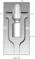
- spherical particles having a diameter of 100 ⁇ m and a density of 2,000 kg/m 3 were simulated entering the enclosure 100 through the entry port 108.
- Pathlines depicted in FIG. 10 show that most of these particles were removed from the enclosure 100 through the outlets 109 before they entered the chamber region 106 of the enclosure 100.
- a disk or plate included on the part carrier such as plate 303 ( FIG. 3 ), could catch these large particles before they entered the chamber region and could help direct smaller particles and air entering through the entry port 108 to the outlets 109 to be removed from the enclosure.
- FIG. 11 depicts pathlines which show that the particles entering the enclosure 100 through the entry port 108 and exiting the enclosure 100 through the outlets 109. The particles did not enter the chamber region 106, even when there is no gripping member 301 occupying space within the entry port 108. Thus, it is unlikely that contaminants having a diameter of less than 100 ⁇ m and a density of 2,000 kg/m 3 would enter the enclosure 100 through the entry port 108 in the space between gripping members 301.
Landscapes
- Chemical & Material Sciences (AREA)
- Engineering & Computer Science (AREA)
- Materials Engineering (AREA)
- Organic Chemistry (AREA)
- General Chemical & Material Sciences (AREA)
- Chemical Kinetics & Catalysis (AREA)
- Life Sciences & Earth Sciences (AREA)
- Geochemistry & Mineralogy (AREA)
- Surface Treatment Of Glass (AREA)
- Coating Apparatus (AREA)
- Re-Forming, After-Treatment, Cutting And Transporting Of Glass Products (AREA)
- Application Of Or Painting With Fluid Materials (AREA)
- Glass Compositions (AREA)
- Electroluminescent Light Sources (AREA)
Claims (17)
- Gehäuse zum Bereitstellen einer kontrollierten Umgebung, umfassend:eine Mittelebene, die sich durch ein oberes Ende des Gehäuses und ein unteres Ende des Gehäuses erstreckt und das Gehäuse entlang einer Breite des Gehäuses halbiert;einen Einlass an dem unteren Ende des Gehäuses mit einer Einlassbreite, WEinlass;eine Gehäusewand, die sich von dem Einlass zu dem oberen Ende des Gehäuses erstreckt, wobei die Gehäusewand einen Kammerbereich und einen Übergangsbereich zwischen dem Einlass und dem Kammerbereich umfasst, wobei eine Breite des Kammerbereichs, WKammer, im Wesentlichen konstant durch den Kammerbereich ist, die Breite des Gehäuses in dem Übergangsbereich von WKammer zu WEinlass abnimmt und ein Verhältnis von WEinlass zu WKammer von 1:2 bis 1:5 ist;eine Eintrittsöffnung an dem oberen Ende des Gehäuses, die konfiguriert ist, um einen Teileträger aufzunehmen; undeinen Auslass zwischen der Eintrittsöffnung und dem Kammerbereich der Gehäusewand;wobei die Mittelebene durch den Einlass und die Eintrittsöffnung des Gehäuses verläuft und sich der Auslass entlang einer Auslassachse erstreckt, die in einem Nichtnullwinkel in Bezug auf die Mittelebene ausgerichtet ist.
- Gehäuse nach Anspruch 1, wobei das Gehäuse Reflexionssymmetrie in Bezug auf die Mittelebene umfasst.
- Gehäuse nach Anspruch 1, wobei die Breite des Gehäuses von WEinlass zu WKammer über eine Strecke von 200 mm bis 900 mm übergeht.
- Gehäuse nach Anspruch 1, wobei WEinlass von 4 mm bis 45 mm ist.
- Gehäuse nach Anspruch 1, wobei WKammer von 20 mm bis 90 mm ist.
- Gehäuse nach Anspruch 1, wobei die Gehäusewand eine S-förmige Kurve mit einem Wendepunkt innerhalb des Übergangsbereichs umfasst.
- Gehäuse nach Anspruch 1, wobei die Auslassachse normal in Bezug auf die Mittelebene ist.
- Fertigungslinie zur Herstellung von Glasartikeln, umfassend:das Gehäuse nach Anspruch 1; undeinen Teileträger, wobei ein Greifelement des Teileträgers durch die Eintrittsöffnung positioniert ist und der Teileträger konfiguriert ist, um einen Glasartikel durch den Kammerbereich des Gehäuses zu bewegen.
- Fertigungslinie nach Anspruch 8, wobei der Teileträger eine Platte umfasst, die zwischen der Eintrittsöffnung und dem Kammerbereich positioniert ist und sich entlang einer Ebene normal zu der Mittelebene erstreckt, wobei sich das Greifelement durch die Platte erstreckt.
- Fertigungslinie nach Anspruch 9, wobei die Platte eine Breite, WPlatte, aufweist, die größer als oder gleich WKammer ist.
- Fertigungslinie nach Anspruch 9, wobei die Eintrittsöffnung eine Breite, WEitritt, aufweist und die Breite der Platte WPlatte größer als die Breite der Eintrittsöffnung, WEitritt, ist.
- Fertigungslinie nach Anspruch 11, wobei die Breite der Eintrittsöffnung, WEitritt, weniger als die Breite des Kammerbereichs, WKammer, ist.
- Fertigungslinie nach Anspruch 9, wobei sich die Platte in den Auslass erstreckt.
- Fertigungslinie nach Anspruch 9, wobei die Platte eine Scheibe mit einem Durchmesser größer als oder gleich WKammer umfasst.
- Fertigungslinie nach Anspruch 8, wobei die Auslassachse normal in Bezug auf die Mittelebene ist.
- Verfahren zum Transportieren eines beschichteten Artikels, wobei das Verfahren Folgendes umfasst:Positionieren des beschichteten Artikels innerhalb eines Gehäuses, wobei das Gehäuse Folgendes umfasst:eine Mittelebene, die sich durch ein oberes Ende des Gehäuses und ein unteres Ende des Gehäuses erstreckt und das Gehäuse entlang einer Breite des Gehäuses halbiert;einen Einlass an dem unteren Ende des Gehäuses mit einer Einlassbreite, WEinlass;eine Gehäusewand, die sich von dem Einlass zu dem oberen Ende des Gehäuses erstreckt, wobei die Gehäusewand einen Kammerbereich und einen Übergangsbereich zwischen dem Einlass und dem Kammerbereich umfasst, wobei eine Breite des Kammerbereichs, WKammer, im Wesentlichen konstant durch den Kammerbereich ist, die Breite des Gehäuses in dem Übergangsbereich von WKammer zu WEinlass abnimmt und ein Verhältnis von WEinlass zu WKammer von 1:2 bis 1:5 ist;eine Eintrittsöffnung an dem oberen Ende des Gehäuses, die konfiguriert ist, um einen Teileträger aufzunehmen; undeinen Auslass zwischen der Eintrittsöffnung und dem Kammerbereich der Gehäusewand;wobei die Mittelebene durch den Einlass und die Eintrittsöffnung des Gehäuses verläuft und sich der Auslass entlang einer Auslassachse erstreckt, die in einem Nichtnullwinkel in Bezug auf die Mittelebene ausgerichtet ist;Zuführen eines Stroms an Fluid zu dem Gehäuse durch den Einlass;Entfernen eines Stroms an Fluid aus dem Gehäuse durch den Auslass; undBewegen des beschichteten Artikels entlang eines Weges durch das Gehäuse, wobei der Weg im Wesentlichen parallel zu der Mittelebene ist.
- Verfahren nach Anspruch 16, wobei Dämpfe aus dem beschichteten Artikel während des Bewegens des beschichteten Artikels durch das Gehäuse verdampfen und aus dem Gehäuse durch den Auslass extrahiert werden.
Applications Claiming Priority (2)
| Application Number | Priority Date | Filing Date | Title |
|---|---|---|---|
| US202063071570P | 2020-08-28 | 2020-08-28 | |
| PCT/US2021/044584 WO2022046377A1 (en) | 2020-08-28 | 2021-08-05 | Enclosures for providing a controlled environment during the production of glass articles |
Publications (2)
| Publication Number | Publication Date |
|---|---|
| EP4204376A1 EP4204376A1 (de) | 2023-07-05 |
| EP4204376B1 true EP4204376B1 (de) | 2024-06-12 |
Family
ID=77519821
Family Applications (1)
| Application Number | Title | Priority Date | Filing Date |
|---|---|---|---|
| EP21762251.3A Active EP4204376B1 (de) | 2020-08-28 | 2021-08-05 | Gehäuse zur bereitstellung einer kontrollierten umgebung während der herstellung von glasartikeln |
Country Status (7)
| Country | Link |
|---|---|
| US (2) | US12338155B2 (de) |
| EP (1) | EP4204376B1 (de) |
| JP (1) | JP7822556B2 (de) |
| KR (1) | KR20230058656A (de) |
| CN (1) | CN116034096B (de) |
| MX (1) | MX2023002428A (de) |
| WO (1) | WO2022046377A1 (de) |
Family Cites Families (21)
| Publication number | Priority date | Publication date | Assignee | Title |
|---|---|---|---|---|
| US3694872A (en) * | 1965-05-13 | 1972-10-03 | Monsanto Co | Apparatus for drawing thermo-plastic filaments in a high temperature gas vortex |
| US3623854A (en) * | 1968-08-28 | 1971-11-30 | Owens Illinois Inc | Vapor treatment of containers with finish air barrier |
| US3615327A (en) * | 1969-08-20 | 1971-10-26 | Owens Illinois Inc | Methods and apparatus for applying oxide coating to glass containers |
| CA927690A (en) * | 1970-07-13 | 1973-06-05 | Ball Corporation | Apparatus and method for treating vitreous surfaces |
| US3895126A (en) * | 1973-05-24 | 1975-07-15 | Indian Head Inc | Resin bottle cladding system |
| JPS51126209A (en) * | 1975-04-25 | 1976-11-04 | Central Glass Co Ltd | Method and apparatus for production of which reflects heat rays |
| JPS5359738A (en) * | 1976-11-10 | 1978-05-29 | Onoda Cement Co Ltd | Continuous electrostatic powder coating and its equipment |
| JPS54113639A (en) * | 1978-02-27 | 1979-09-05 | Nippon Glass | Protection of mouth portion in glass bottle plastic coating by powder electrostatic coating |
| US4248615A (en) * | 1979-11-19 | 1981-02-03 | Owens-Corning Fiberglas Corporation | Pollution abating, energy conserving glass manufacturing process |
| GB8531424D0 (en) * | 1985-12-20 | 1986-02-05 | Glaverbel | Coating glass |
| US5090985A (en) * | 1989-10-17 | 1992-02-25 | Libbey-Owens-Ford Co. | Method for preparing vaporized reactants for chemical vapor deposition |
| JPH1067540A (ja) * | 1996-08-26 | 1998-03-10 | Asahi Beer Packs:Kk | ガラスゲル薄膜形成装置 |
| DE19719133C2 (de) * | 1997-05-07 | 1999-09-02 | Heraeus Quarzglas | Glocke aus Quarzglas und Verfahren für ihre Herstellung |
| US9776903B2 (en) * | 2010-06-17 | 2017-10-03 | Johns Manville | Apparatus, systems and methods for processing molten glass |
| US9011952B2 (en) * | 2011-11-09 | 2015-04-21 | Council Of Scientific & Industrial Research | Method and apparatus for the separation of seeds from fruit pulp/slurry/pomace |
| JP5935508B2 (ja) | 2012-05-28 | 2016-06-15 | 住友電気工業株式会社 | ガラス母材の製造方法および製造装置 |
| CN203297165U (zh) | 2013-04-26 | 2013-11-20 | 苏州尚科洁净技术有限公司 | 洁净微环境装置 |
| CN108467210B (zh) * | 2013-06-07 | 2020-09-29 | 株式会社藤仓 | 光纤裸线覆盖装置以及光纤裸线覆盖方法 |
| ES2673428T3 (es) * | 2015-06-12 | 2018-06-21 | Borealis Ag | Procedimiento y aparato para la polimerización de olefinas en fase gaseosa |
| CN205856318U (zh) * | 2016-08-10 | 2017-01-04 | 福建新福兴玻璃有限公司 | 玻璃镀膜生产线 |
| KR102633318B1 (ko) | 2017-11-27 | 2024-02-05 | 에이에스엠 아이피 홀딩 비.브이. | 청정 소형 구역을 포함한 장치 |
-
2021
- 2021-08-05 EP EP21762251.3A patent/EP4204376B1/de active Active
- 2021-08-05 CN CN202180053698.1A patent/CN116034096B/zh active Active
- 2021-08-05 KR KR1020237009768A patent/KR20230058656A/ko not_active Withdrawn
- 2021-08-05 MX MX2023002428A patent/MX2023002428A/es unknown
- 2021-08-05 WO PCT/US2021/044584 patent/WO2022046377A1/en not_active Ceased
- 2021-08-05 JP JP2023513692A patent/JP7822556B2/ja active Active
- 2021-08-24 US US17/410,131 patent/US12338155B2/en active Active
-
2025
- 2025-05-22 US US19/216,401 patent/US20250282666A1/en active Pending
Also Published As
| Publication number | Publication date |
|---|---|
| CN116034096A (zh) | 2023-04-28 |
| US12338155B2 (en) | 2025-06-24 |
| MX2023002428A (es) | 2023-05-19 |
| CN116034096B (zh) | 2025-11-18 |
| EP4204376A1 (de) | 2023-07-05 |
| WO2022046377A1 (en) | 2022-03-03 |
| KR20230058656A (ko) | 2023-05-03 |
| US20220064046A1 (en) | 2022-03-03 |
| JP7822556B2 (ja) | 2026-03-03 |
| US20250282666A1 (en) | 2025-09-11 |
| JP2023539622A (ja) | 2023-09-15 |
Similar Documents
| Publication | Publication Date | Title |
|---|---|---|
| KR102234619B1 (ko) | 액 공급 노즐 및 기판 처리 장치 | |
| KR101798261B1 (ko) | 프로세스 도구에서 메커니즘들을 이동시킴으로써 생성된 입자 오염의 감소 | |
| CN110461570B (zh) | 气流控制装置及拉伸膜的制造方法 | |
| CN201812803U (zh) | 大气传输单元及具有该大气传输单元的晶片传输系统 | |
| JP6152570B2 (ja) | ガラス処理装置及びガラス処理方法 | |
| EP4204376B1 (de) | Gehäuse zur bereitstellung einer kontrollierten umgebung während der herstellung von glasartikeln | |
| US4860643A (en) | Ventilated clean room work station with aerodynamic exhaust baffle | |
| TWI446480B (zh) | 基板冷卻裝置 | |
| TWI674642B (zh) | 具有微粒減少特徵之基板容器及其相關方法 | |
| EP1738123B1 (de) | Trockenumwandlungsverfahren und -vorrichtung | |
| JP2007137502A (ja) | 連続加熱方法およびその装置 | |
| CN102909205A (zh) | 排气系统及其方法 | |
| TW201637811A (zh) | 溶液製膜方法及設備 | |
| JP2006049493A (ja) | 基板搬送モジュールならびにそれを用いた基板搬送装置および基板搬送方法 | |
| TW202146352A (zh) | 用於減少處理期間的靜電電荷的玻璃表面蝕刻 | |
| US11492290B2 (en) | Coating apparatus for containers | |
| US20040266208A1 (en) | Method for preventing particle-based contamination of substrates and structure therefor | |
| CN117597315A (zh) | 用于制造玻璃带的方法和设备 | |
| KR101011768B1 (ko) | 기체유동제어장치 | |
| CN109926253A (zh) | 一种提高酒瓶喷涂质量的设备 | |
| WO2024049727A1 (en) | Methods and apparatus for manufacturing a ribbon | |
| TW202309989A (zh) | 無塵室 | |
| EP3445731A1 (de) | Beschichtungsvorrichtung für behälter | |
| CN118140095A (zh) | 用于制药或生物技术过程的机器,用于实现机器的组件和方法 | |
| EP3381875A1 (de) | Beschichtungsvorrichtung für behälter mit mitteln zur druckregelung |
Legal Events
| Date | Code | Title | Description |
|---|---|---|---|
| STAA | Information on the status of an ep patent application or granted ep patent |
Free format text: STATUS: UNKNOWN |
|
| STAA | Information on the status of an ep patent application or granted ep patent |
Free format text: STATUS: THE INTERNATIONAL PUBLICATION HAS BEEN MADE |
|
| PUAI | Public reference made under article 153(3) epc to a published international application that has entered the european phase |
Free format text: ORIGINAL CODE: 0009012 |
|
| STAA | Information on the status of an ep patent application or granted ep patent |
Free format text: STATUS: REQUEST FOR EXAMINATION WAS MADE |
|
| 17P | Request for examination filed |
Effective date: 20230316 |
|
| AK | Designated contracting states |
Kind code of ref document: A1 Designated state(s): AL AT BE BG CH CY CZ DE DK EE ES FI FR GB GR HR HU IE IS IT LI LT LU LV MC MK MT NL NO PL PT RO RS SE SI SK SM TR |
|
| DAV | Request for validation of the european patent (deleted) | ||
| DAX | Request for extension of the european patent (deleted) | ||
| GRAP | Despatch of communication of intention to grant a patent |
Free format text: ORIGINAL CODE: EPIDOSNIGR1 |
|
| STAA | Information on the status of an ep patent application or granted ep patent |
Free format text: STATUS: GRANT OF PATENT IS INTENDED |
|
| INTG | Intention to grant announced |
Effective date: 20240103 |
|
| GRAS | Grant fee paid |
Free format text: ORIGINAL CODE: EPIDOSNIGR3 |
|
| GRAA | (expected) grant |
Free format text: ORIGINAL CODE: 0009210 |
|
| STAA | Information on the status of an ep patent application or granted ep patent |
Free format text: STATUS: THE PATENT HAS BEEN GRANTED |
|
| AK | Designated contracting states |
Kind code of ref document: B1 Designated state(s): AL AT BE BG CH CY CZ DE DK EE ES FI FR GB GR HR HU IE IS IT LI LT LU LV MC MK MT NL NO PL PT RO RS SE SI SK SM TR |
|
| REG | Reference to a national code |
Ref country code: GB Ref legal event code: FG4D |
|
| REG | Reference to a national code |
Ref country code: CH Ref legal event code: EP |
|
| REG | Reference to a national code |
Ref country code: DE Ref legal event code: R096 Ref document number: 602021014425 Country of ref document: DE |
|
| REG | Reference to a national code |
Ref country code: IE Ref legal event code: FG4D |
|
| PG25 | Lapsed in a contracting state [announced via postgrant information from national office to epo] |
Ref country code: BG Free format text: LAPSE BECAUSE OF FAILURE TO SUBMIT A TRANSLATION OF THE DESCRIPTION OR TO PAY THE FEE WITHIN THE PRESCRIBED TIME-LIMIT Effective date: 20240612 |
|
| PG25 | Lapsed in a contracting state [announced via postgrant information from national office to epo] |
Ref country code: FI Free format text: LAPSE BECAUSE OF FAILURE TO SUBMIT A TRANSLATION OF THE DESCRIPTION OR TO PAY THE FEE WITHIN THE PRESCRIBED TIME-LIMIT Effective date: 20240612 Ref country code: HR Free format text: LAPSE BECAUSE OF FAILURE TO SUBMIT A TRANSLATION OF THE DESCRIPTION OR TO PAY THE FEE WITHIN THE PRESCRIBED TIME-LIMIT Effective date: 20240612 |
|
| REG | Reference to a national code |
Ref country code: LT Ref legal event code: MG9D |
|
| PG25 | Lapsed in a contracting state [announced via postgrant information from national office to epo] |
Ref country code: GR Free format text: LAPSE BECAUSE OF FAILURE TO SUBMIT A TRANSLATION OF THE DESCRIPTION OR TO PAY THE FEE WITHIN THE PRESCRIBED TIME-LIMIT Effective date: 20240913 |
|
| REG | Reference to a national code |
Ref country code: NL Ref legal event code: MP Effective date: 20240612 |
|
| PG25 | Lapsed in a contracting state [announced via postgrant information from national office to epo] |
Ref country code: ES Free format text: LAPSE BECAUSE OF FAILURE TO SUBMIT A TRANSLATION OF THE DESCRIPTION OR TO PAY THE FEE WITHIN THE PRESCRIBED TIME-LIMIT Effective date: 20240612 |
|
| PG25 | Lapsed in a contracting state [announced via postgrant information from national office to epo] |
Ref country code: LV Free format text: LAPSE BECAUSE OF FAILURE TO SUBMIT A TRANSLATION OF THE DESCRIPTION OR TO PAY THE FEE WITHIN THE PRESCRIBED TIME-LIMIT Effective date: 20240612 |
|
| PG25 | Lapsed in a contracting state [announced via postgrant information from national office to epo] |
Ref country code: NO Free format text: LAPSE BECAUSE OF FAILURE TO SUBMIT A TRANSLATION OF THE DESCRIPTION OR TO PAY THE FEE WITHIN THE PRESCRIBED TIME-LIMIT Effective date: 20240912 Ref country code: LV Free format text: LAPSE BECAUSE OF FAILURE TO SUBMIT A TRANSLATION OF THE DESCRIPTION OR TO PAY THE FEE WITHIN THE PRESCRIBED TIME-LIMIT Effective date: 20240612 Ref country code: HR Free format text: LAPSE BECAUSE OF FAILURE TO SUBMIT A TRANSLATION OF THE DESCRIPTION OR TO PAY THE FEE WITHIN THE PRESCRIBED TIME-LIMIT Effective date: 20240612 Ref country code: GR Free format text: LAPSE BECAUSE OF FAILURE TO SUBMIT A TRANSLATION OF THE DESCRIPTION OR TO PAY THE FEE WITHIN THE PRESCRIBED TIME-LIMIT Effective date: 20240913 Ref country code: FI Free format text: LAPSE BECAUSE OF FAILURE TO SUBMIT A TRANSLATION OF THE DESCRIPTION OR TO PAY THE FEE WITHIN THE PRESCRIBED TIME-LIMIT Effective date: 20240612 Ref country code: ES Free format text: LAPSE BECAUSE OF FAILURE TO SUBMIT A TRANSLATION OF THE DESCRIPTION OR TO PAY THE FEE WITHIN THE PRESCRIBED TIME-LIMIT Effective date: 20240612 Ref country code: BG Free format text: LAPSE BECAUSE OF FAILURE TO SUBMIT A TRANSLATION OF THE DESCRIPTION OR TO PAY THE FEE WITHIN THE PRESCRIBED TIME-LIMIT Effective date: 20240612 Ref country code: RS Free format text: LAPSE BECAUSE OF FAILURE TO SUBMIT A TRANSLATION OF THE DESCRIPTION OR TO PAY THE FEE WITHIN THE PRESCRIBED TIME-LIMIT Effective date: 20240912 |
|
| PG25 | Lapsed in a contracting state [announced via postgrant information from national office to epo] |
Ref country code: NL Free format text: LAPSE BECAUSE OF FAILURE TO SUBMIT A TRANSLATION OF THE DESCRIPTION OR TO PAY THE FEE WITHIN THE PRESCRIBED TIME-LIMIT Effective date: 20240612 |
|
| REG | Reference to a national code |
Ref country code: AT Ref legal event code: MK05 Ref document number: 1694108 Country of ref document: AT Kind code of ref document: T Effective date: 20240612 |
|
| PG25 | Lapsed in a contracting state [announced via postgrant information from national office to epo] |
Ref country code: NL Free format text: LAPSE BECAUSE OF FAILURE TO SUBMIT A TRANSLATION OF THE DESCRIPTION OR TO PAY THE FEE WITHIN THE PRESCRIBED TIME-LIMIT Effective date: 20240612 |
|
| PG25 | Lapsed in a contracting state [announced via postgrant information from national office to epo] |
Ref country code: PT Free format text: LAPSE BECAUSE OF FAILURE TO SUBMIT A TRANSLATION OF THE DESCRIPTION OR TO PAY THE FEE WITHIN THE PRESCRIBED TIME-LIMIT Effective date: 20241014 |
|
| PG25 | Lapsed in a contracting state [announced via postgrant information from national office to epo] |
Ref country code: PT Free format text: LAPSE BECAUSE OF FAILURE TO SUBMIT A TRANSLATION OF THE DESCRIPTION OR TO PAY THE FEE WITHIN THE PRESCRIBED TIME-LIMIT Effective date: 20241014 |
|
| PG25 | Lapsed in a contracting state [announced via postgrant information from national office to epo] |
Ref country code: PL Free format text: LAPSE BECAUSE OF FAILURE TO SUBMIT A TRANSLATION OF THE DESCRIPTION OR TO PAY THE FEE WITHIN THE PRESCRIBED TIME-LIMIT Effective date: 20240612 |
|
| PG25 | Lapsed in a contracting state [announced via postgrant information from national office to epo] |
Ref country code: EE Free format text: LAPSE BECAUSE OF FAILURE TO SUBMIT A TRANSLATION OF THE DESCRIPTION OR TO PAY THE FEE WITHIN THE PRESCRIBED TIME-LIMIT Effective date: 20240612 |
|
| PG25 | Lapsed in a contracting state [announced via postgrant information from national office to epo] |
Ref country code: IS Free format text: LAPSE BECAUSE OF FAILURE TO SUBMIT A TRANSLATION OF THE DESCRIPTION OR TO PAY THE FEE WITHIN THE PRESCRIBED TIME-LIMIT Effective date: 20241012 Ref country code: AT Free format text: LAPSE BECAUSE OF FAILURE TO SUBMIT A TRANSLATION OF THE DESCRIPTION OR TO PAY THE FEE WITHIN THE PRESCRIBED TIME-LIMIT Effective date: 20240612 |
|
| PG25 | Lapsed in a contracting state [announced via postgrant information from national office to epo] |
Ref country code: CZ Free format text: LAPSE BECAUSE OF FAILURE TO SUBMIT A TRANSLATION OF THE DESCRIPTION OR TO PAY THE FEE WITHIN THE PRESCRIBED TIME-LIMIT Effective date: 20240612 |
|
| PG25 | Lapsed in a contracting state [announced via postgrant information from national office to epo] |
Ref country code: RO Free format text: LAPSE BECAUSE OF FAILURE TO SUBMIT A TRANSLATION OF THE DESCRIPTION OR TO PAY THE FEE WITHIN THE PRESCRIBED TIME-LIMIT Effective date: 20240612 Ref country code: SK Free format text: LAPSE BECAUSE OF FAILURE TO SUBMIT A TRANSLATION OF THE DESCRIPTION OR TO PAY THE FEE WITHIN THE PRESCRIBED TIME-LIMIT Effective date: 20240612 |
|
| PG25 | Lapsed in a contracting state [announced via postgrant information from national office to epo] |
Ref country code: SM Free format text: LAPSE BECAUSE OF FAILURE TO SUBMIT A TRANSLATION OF THE DESCRIPTION OR TO PAY THE FEE WITHIN THE PRESCRIBED TIME-LIMIT Effective date: 20240612 |
|
| PG25 | Lapsed in a contracting state [announced via postgrant information from national office to epo] |
Ref country code: SM Free format text: LAPSE BECAUSE OF FAILURE TO SUBMIT A TRANSLATION OF THE DESCRIPTION OR TO PAY THE FEE WITHIN THE PRESCRIBED TIME-LIMIT Effective date: 20240612 Ref country code: SK Free format text: LAPSE BECAUSE OF FAILURE TO SUBMIT A TRANSLATION OF THE DESCRIPTION OR TO PAY THE FEE WITHIN THE PRESCRIBED TIME-LIMIT Effective date: 20240612 Ref country code: RO Free format text: LAPSE BECAUSE OF FAILURE TO SUBMIT A TRANSLATION OF THE DESCRIPTION OR TO PAY THE FEE WITHIN THE PRESCRIBED TIME-LIMIT Effective date: 20240612 Ref country code: PL Free format text: LAPSE BECAUSE OF FAILURE TO SUBMIT A TRANSLATION OF THE DESCRIPTION OR TO PAY THE FEE WITHIN THE PRESCRIBED TIME-LIMIT Effective date: 20240612 Ref country code: IS Free format text: LAPSE BECAUSE OF FAILURE TO SUBMIT A TRANSLATION OF THE DESCRIPTION OR TO PAY THE FEE WITHIN THE PRESCRIBED TIME-LIMIT Effective date: 20241012 Ref country code: EE Free format text: LAPSE BECAUSE OF FAILURE TO SUBMIT A TRANSLATION OF THE DESCRIPTION OR TO PAY THE FEE WITHIN THE PRESCRIBED TIME-LIMIT Effective date: 20240612 Ref country code: CZ Free format text: LAPSE BECAUSE OF FAILURE TO SUBMIT A TRANSLATION OF THE DESCRIPTION OR TO PAY THE FEE WITHIN THE PRESCRIBED TIME-LIMIT Effective date: 20240612 Ref country code: AT Free format text: LAPSE BECAUSE OF FAILURE TO SUBMIT A TRANSLATION OF THE DESCRIPTION OR TO PAY THE FEE WITHIN THE PRESCRIBED TIME-LIMIT Effective date: 20240612 |
|
| REG | Reference to a national code |
Ref country code: DE Ref legal event code: R097 Ref document number: 602021014425 Country of ref document: DE |
|
| REG | Reference to a national code |
Ref country code: CH Ref legal event code: PL |
|
| PG25 | Lapsed in a contracting state [announced via postgrant information from national office to epo] |
Ref country code: DK Free format text: LAPSE BECAUSE OF FAILURE TO SUBMIT A TRANSLATION OF THE DESCRIPTION OR TO PAY THE FEE WITHIN THE PRESCRIBED TIME-LIMIT Effective date: 20240612 |
|
| PG25 | Lapsed in a contracting state [announced via postgrant information from national office to epo] |
Ref country code: LU Free format text: LAPSE BECAUSE OF NON-PAYMENT OF DUE FEES Effective date: 20240805 |
|
| PLBE | No opposition filed within time limit |
Free format text: ORIGINAL CODE: 0009261 |
|
| STAA | Information on the status of an ep patent application or granted ep patent |
Free format text: STATUS: NO OPPOSITION FILED WITHIN TIME LIMIT |
|
| PG25 | Lapsed in a contracting state [announced via postgrant information from national office to epo] |
Ref country code: MC Free format text: LAPSE BECAUSE OF FAILURE TO SUBMIT A TRANSLATION OF THE DESCRIPTION OR TO PAY THE FEE WITHIN THE PRESCRIBED TIME-LIMIT Effective date: 20240612 Ref country code: CH Free format text: LAPSE BECAUSE OF NON-PAYMENT OF DUE FEES Effective date: 20240831 |
|
| 26N | No opposition filed |
Effective date: 20250313 |
|
| REG | Reference to a national code |
Ref country code: BE Ref legal event code: MM Effective date: 20240831 |
|
| PG25 | Lapsed in a contracting state [announced via postgrant information from national office to epo] |
Ref country code: BE Free format text: LAPSE BECAUSE OF NON-PAYMENT OF DUE FEES Effective date: 20240831 |
|
| PG25 | Lapsed in a contracting state [announced via postgrant information from national office to epo] |
Ref country code: IE Free format text: LAPSE BECAUSE OF NON-PAYMENT OF DUE FEES Effective date: 20240805 |
|
| PG25 | Lapsed in a contracting state [announced via postgrant information from national office to epo] |
Ref country code: SE Free format text: LAPSE BECAUSE OF FAILURE TO SUBMIT A TRANSLATION OF THE DESCRIPTION OR TO PAY THE FEE WITHIN THE PRESCRIBED TIME-LIMIT Effective date: 20240612 |
|
| PGFP | Annual fee paid to national office [announced via postgrant information from national office to epo] |
Ref country code: DE Payment date: 20250709 Year of fee payment: 5 |
|
| PGFP | Annual fee paid to national office [announced via postgrant information from national office to epo] |
Ref country code: IT Payment date: 20250811 Year of fee payment: 5 |
|
| PGFP | Annual fee paid to national office [announced via postgrant information from national office to epo] |
Ref country code: GB Payment date: 20250710 Year of fee payment: 5 |
|
| PGFP | Annual fee paid to national office [announced via postgrant information from national office to epo] |
Ref country code: FR Payment date: 20250709 Year of fee payment: 5 |
|
| PG25 | Lapsed in a contracting state [announced via postgrant information from national office to epo] |
Ref country code: CY Free format text: LAPSE BECAUSE OF FAILURE TO SUBMIT A TRANSLATION OF THE DESCRIPTION OR TO PAY THE FEE WITHIN THE PRESCRIBED TIME-LIMIT; INVALID AB INITIO Effective date: 20210805 |
|
| PG25 | Lapsed in a contracting state [announced via postgrant information from national office to epo] |
Ref country code: HU Free format text: LAPSE BECAUSE OF FAILURE TO SUBMIT A TRANSLATION OF THE DESCRIPTION OR TO PAY THE FEE WITHIN THE PRESCRIBED TIME-LIMIT; INVALID AB INITIO Effective date: 20210805 |