EP4201616B1 - Système d'alimentation pour outils de poinçonnage - Google Patents
Système d'alimentation pour outils de poinçonnage Download PDFInfo
- Publication number
- EP4201616B1 EP4201616B1 EP21942799.4A EP21942799A EP4201616B1 EP 4201616 B1 EP4201616 B1 EP 4201616B1 EP 21942799 A EP21942799 A EP 21942799A EP 4201616 B1 EP4201616 B1 EP 4201616B1
- Authority
- EP
- European Patent Office
- Prior art keywords
- locking
- disposed
- storage rack
- rods
- frame
- Prior art date
- Legal status (The legal status is an assumption and is not a legal conclusion. Google has not performed a legal analysis and makes no representation as to the accuracy of the status listed.)
- Active
Links
Images

Classifications
-
- B—PERFORMING OPERATIONS; TRANSPORTING
- B26—HAND CUTTING TOOLS; CUTTING; SEVERING
- B26D—CUTTING; DETAILS COMMON TO MACHINES FOR PERFORATING, PUNCHING, CUTTING-OUT, STAMPING-OUT OR SEVERING
- B26D7/00—Details of apparatus for cutting, cutting-out, stamping-out, punching, perforating, or severing by means other than cutting
- B26D7/08—Means for treating work or cutting member to facilitate cutting
-
- B—PERFORMING OPERATIONS; TRANSPORTING
- B26—HAND CUTTING TOOLS; CUTTING; SEVERING
- B26F—PERFORATING; PUNCHING; CUTTING-OUT; STAMPING-OUT; SEVERING BY MEANS OTHER THAN CUTTING
- B26F1/00—Perforating; Punching; Cutting-out; Stamping-out; Apparatus therefor
- B26F1/38—Cutting-out; Stamping-out
- B26F1/44—Cutters therefor; Dies therefor
-
- B—PERFORMING OPERATIONS; TRANSPORTING
- B25—HAND TOOLS; PORTABLE POWER-DRIVEN TOOLS; MANIPULATORS
- B25H—WORKSHOP EQUIPMENT, e.g. FOR MARKING-OUT WORK; STORAGE MEANS FOR WORKSHOPS
- B25H3/00—Storage means or arrangements for workshops facilitating access to, or handling of, work tools or instruments
- B25H3/04—Racks
-
- B—PERFORMING OPERATIONS; TRANSPORTING
- B26—HAND CUTTING TOOLS; CUTTING; SEVERING
- B26D—CUTTING; DETAILS COMMON TO MACHINES FOR PERFORATING, PUNCHING, CUTTING-OUT, STAMPING-OUT OR SEVERING
- B26D5/00—Arrangements for operating and controlling machines or devices for cutting, cutting-out, stamping-out, punching, perforating, or severing by means other than cutting
-
- B—PERFORMING OPERATIONS; TRANSPORTING
- B26—HAND CUTTING TOOLS; CUTTING; SEVERING
- B26D—CUTTING; DETAILS COMMON TO MACHINES FOR PERFORATING, PUNCHING, CUTTING-OUT, STAMPING-OUT OR SEVERING
- B26D7/00—Details of apparatus for cutting, cutting-out, stamping-out, punching, perforating, or severing by means other than cutting
- B26D7/26—Means for mounting or adjusting the cutting member; Means for adjusting the stroke of the cutting member
-
- B—PERFORMING OPERATIONS; TRANSPORTING
- B26—HAND CUTTING TOOLS; CUTTING; SEVERING
- B26F—PERFORATING; PUNCHING; CUTTING-OUT; STAMPING-OUT; SEVERING BY MEANS OTHER THAN CUTTING
- B26F1/00—Perforating; Punching; Cutting-out; Stamping-out; Apparatus therefor
- B26F1/38—Cutting-out; Stamping-out
-
- B—PERFORMING OPERATIONS; TRANSPORTING
- B26—HAND CUTTING TOOLS; CUTTING; SEVERING
- B26F—PERFORATING; PUNCHING; CUTTING-OUT; STAMPING-OUT; SEVERING BY MEANS OTHER THAN CUTTING
- B26F1/00—Perforating; Punching; Cutting-out; Stamping-out; Apparatus therefor
- B26F1/38—Cutting-out; Stamping-out
- B26F1/40—Cutting-out; Stamping-out using a press, e.g. of the ram type
- B26F1/405—Travelling head presses
-
- B—PERFORMING OPERATIONS; TRANSPORTING
- B26—HAND CUTTING TOOLS; CUTTING; SEVERING
- B26D—CUTTING; DETAILS COMMON TO MACHINES FOR PERFORATING, PUNCHING, CUTTING-OUT, STAMPING-OUT OR SEVERING
- B26D7/00—Details of apparatus for cutting, cutting-out, stamping-out, punching, perforating, or severing by means other than cutting
- B26D7/26—Means for mounting or adjusting the cutting member; Means for adjusting the stroke of the cutting member
- B26D2007/2607—Means for mounting or adjusting the cutting member; Means for adjusting the stroke of the cutting member for mounting die cutters
Definitions
- the present invention relates to the technical field of automatic cutting machines, and in particular to a die cutter supply system and a high-speed smart cutting and processing center using the system.
- CN 107 097 294 A discloses a cutting machine for sheet cutting which comprises a die cutting head, a cutting die replacement mechanism, a tool magazine, a rack, a bracket and a control box.
- the die cutting head is arranged on the rack which is arranged at one end of the die cutting head.
- the tool magazine is arranged in the bracket.
- the cutting die replacement mechanism is arranged between the tool magazine and the die cutting head.
- a cutting die is arranged under the die cutting head, and the control box is arranged on the rack.
- CN 201 231 508 Y discloses a foam board cutting machine.
- the present invention provides a die cutter supply system and a high-speed smart cutting and processing center using the system, which feature simple structure, small volume and good stability.
- the present invention is achieved by providing a die cutter supply system, which includes a frame and a die cutter storage rack and a drive device disposed within the frame.
- An exit-entry portion for die cutters to enter and exit the storage rack is disposed at back and front sides of the frame respectively.
- a plurality of die cutters are stacked up and down in different layers in the storage rack.
- Guide columns are respectively disposed at four corners of the frame, and guide sleeves slidable cooperating with the guide columns are disposed on the storage rack.
- the drive device drives the storage rack up and down along the guide columns.
- the drive device includes a motor gear box provided with a dual-output shaft, driving belt wheels, a driven shaft, driven bearings, driven belt wheels and synchronous belts.
- the motor gear box is disposed on the top of the frame.
- the locking operation rod is slid up and down along the locking bearings under the drive of the locking cylinder.
- the rotary shaft fixing rod is fixed at a side of the storage rack, and the rotary shaft fixing rod is provided with a plurality of avoiding holes corresponding to a placement position of each layer of die cutter.
- the driving rods, the locking rods and the locking rod rotary shafts are respectively disposed at a side of the placement position of each layer of die cutter by sets.
- the locking rods are provided with a waist-shaped hole, a rotary shaft hole, and an arc-shaped portion.
- the locking rod rotary shafts are penetrated through the rotary shaft fixing rod and the rotary shaft holes of the locking rods to movably connect the locking rods in the avoiding holes of the locking rods.
- One end of the driving rods is fixed on the locking rods, and the other end is movably inserted into the waist-shaped holes of the locking rods.
- the arc-shaped portions of the locking rods are fitted into limiting grooves of side edges of the die cutters.
- the locking operation rod slides up and down and thus drives the locking rods to rotate around the locking rod rotary shafts through the driving rods.
- a roller is disposed at a sidewall of each slideway 7.
- the locking operation rod is provided with a contact block, and an upper travel switch and a lower travel switch cooperating with the contact block are respectively disposed on the frame.
- a cutter rack support column is disposed at the bottom of the storage rack, and a cutter rack limiting column is disposed on the top of the frame 1.
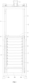
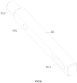
- a preferred embodiment of a die cutter supply system of the present invention includes a frame 1 and a die cutter storage rack 2 and a drive device 3 disposed within the frame 1.
- An exit-entry portion 4 for die cutters A to enter and exit the storage rack 2 is disposed at back and front sides of the frame 1 respectively.
- the exit-entry portion 4 at one side is used to connect with a high-speed smart cutting and processing center to provide a desired die cutter A for the high-speed smart cutting and processing center.
- the exit-entry portion 4 at the other side is used to change and sequentially configure the die cutters A in the frame 1.
- a plurality of die cutters A are stacked up and down in different layers in the storage rack 2.
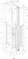
- Guide columns 5 are respectively disposed at four corners of the frame 1.
- Guide sleeves 6 slidably cooperating with the guide columns 5 are disposed on the storage rack 2.
- the drive device 3 drives the storage rack 2 up and down along the guide columns 5.
- the drive device includes a motor gear box 31 provided with a dual output shaft, driving belt wheels 32, a driven shaft 33, driven bearings 34, driven belt wheels 35 and synchronous belts 36.
- the motor gear box 31 is disposed on the top of the frame 1.
- Two driving belt wheels 32 are respectively disposed on both ends of the output shaft.
- Two driven bearings 34 are fixed at a lower portion of the frame 1 and located below the storage rack 2.
- the driven shaft 33 is penetrated through the two driven bearings 34, and the driven belt wheels 35 are disposed on both ends of the driven shaft 33.
- the driving belt wheels 32 drive the driven belt wheels 35 to rotate by the synchronous belts 36.
- a synchronous belt 36 is disposed on left and right sides of the frame 1 respectively, and each synchronous belt 36 is provided with a cutter rack fixing plate 37, one end of the cutter rack fixing plate 37 is fixed on the synchronous belt 36, and the other end is fixed on the storage rack 2 at this side.
- the two synchronous belts 36 drive the storage rack 2 to move up and down along the guide columns 5 through respective cutter rack fixing plates 37 at the same time.
- the structure of the drive device 3 is simplified and the repeatability of the up and down moving position of the storage rack 2 is improved, thereby increasing the running stability.
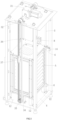
- a plurality of slideways 7 for placing the die cutters A are disposed at the left and right sides of the storage rack 2 respectively and a die cutter locking device 8 for positioning the die cutters A in the slideways 7 is disposed at the right side of the storage rack 2.
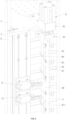
- the die cutter locking device 8 includes a locking cylinder 81, a locking operation rod 82, locking bearings 83, driving rods 84, locking rods 85, locking rod rotary shafts 86, and a rotary shaft fixing rod 87.
- the locking cylinder 81, the locking bearing 83, and the rotary shaft fixing rod 87 are respectively fixed to the storage rack 2.
- the locking cylinder 81 is fixed on an upper portion of the storage rack 2, and the locking operation rod 82 is fixedly connected with an output shaft of the locking cylinder 81.
- the locking operation rod 82 is penetrated through two locking bearings 83 which are fixed on the storage rack 2 and respectively located both ends of the locking operation rod 82.
- the locking operation rod 82 is slid up and down along the locking bearings 83 under the drive of the locking cylinder 81.
- the rotary shaft fixing rod 87 is fixed at a side of the storage rack 2, and the rotary shaft fixing rod 87 is provided with a plurality of avoiding holes 871 each corresponding to a placement position of the each layer of die cutter A.
- the driving rods 84, the locking rods 85 and the locking rod rotary shafts 86 are disposed at a side of the placement position of each layer of die cutter A respectively by sets.
- the locking rod is provided with a waist-shaped hole 851, a rotary shaft hole 852 and an arc-shaped portion 853 respectively, where the waist-shaped hole 851 and the arc-shaped portion 853 are located at both sides of the rotary shaft hole 852.
- the locking rod rotary shafts 86 are penetrated through the rotary shaft fixing rod 87 and the rotary shaft holes 852 of the locking rods 85 to movably connect the locking rods 85 in the locking rod avoiding holes 871 such that the locking rods 85 can rotate around the locking rod rotary shafts 86.
- One end of the driving rods 84 is fixed on the locking rods 85, and the other end is movable inserted into the waist-shaped holes of the locking rods 85.
- the arc-shaped portions 853 of the locking rods 85 are fitted into limiting grooves B of side edges of the die cutters A, as shown in FIG. 5 .
- the locking operation rod 82 slides up and down and thus drives the locking rods 85 to rotate around the locking rod rotary shafts 86 through the driving rods 84, such that the arc-shaped portions 853 of the locking rods 85 are fitted into the limiting grooves B of the die cutters A so as to lock up the die cutters A, or the arc-shaped portions 853 of the locking rods 85 are released from the limiting grooves B of the die cutters A so as to unlock the die cutters A.
- the locking operation rod 82 is provided with a contact block 88, and an upper travel switch 10 and a lower travel switch 11 cooperating with the contact block 88 are respectively disposed on the frame 1.
- the contact block 88 moves up and down along with the locking operation rod 82 to trigger the upper travel switch 10 and the lower travel switch 11 respectively so as to limit the upper and lower positions for the movement of the locking operation rod 82, thereby improving the operation safety of the die cutter locking device 8.
- a roller 9 is disposed at a sidewall of each slideway 7.
- the rollers 9 are located above the die cutters A and close to the exit-entry portion 4 at the back of the frame 1, so as to achieve limiting and guiding effect when the die cutters A are guided into or out of the storage rack 2.
- a cutter rack support column 12 is disposed at the bottom of the storage rack 2 and fixed on the frame 1.
- a cutter rack limiting column 13 is disposed on the top of the frame 1. In this embodiment, four cutter rack support columns 12 are disposed correspondingly at four corners of the bottom of the storage rack 2, and four cutter rack limiting columns 13 are disposed correspondingly at four corners of the top of the frame 1. In this way, the safety and stability of the storage rack 2 can be improved.
- a stop switch 14 triggered by the storage rack 2 is disposed on the frame 1. The stop switch 14 is used to limit a descending position of the storage rack 2, thereby improving the movement safety and stability of the storage rack 2.
- the present invention is achieved by providing a high-speed smart cutting and processing center.
- the high-speed smart cutting and processing center uses the above die cutter supply system.
- the die cutter supply system can automatically provide the die cutters A desired for cutting operation to the high-speed smart cutting and processing center.
Landscapes
- Engineering & Computer Science (AREA)
- Mechanical Engineering (AREA)
- Life Sciences & Earth Sciences (AREA)
- Forests & Forestry (AREA)
- Perforating, Stamping-Out Or Severing By Means Other Than Cutting (AREA)
Claims (6)
- Un système d'alimentation en couteaux de découpe, comprenant :un cadre (1), un support de stockage des couteaux de découpe (2) et un dispositif d'entraînement (3) disposés à l'intérieur du cadre (1), dans lequel une section d'entrée-sortie (4) pour permettre aux couteaux de découpe (A) d'entrer et de sortir du support de stockage (2) est disposée respectivement sur les côtés avant et arrière du cadre (1), une pluralité de couteaux de découpe (A) sont empilés en différentes couches dans le support de stockage (2), des colonnes de guidage (5) sont disposées aux quatre coins du cadre (1), des manchons de guidage (6) coopérant de manière coulissante avec les colonnes de guidage (5) sont disposés sur le support de stockage (2), et le dispositif d'entraînement (3) déplace le support de stockage (2) de haut en bas le long des colonnes de guidage (5) ;caractérisé en ce que le dispositif d'entraînement (3) comprend une boîte de vitesses à moteur (31) équipée d'un arbre de sortie double, des poulies d'entraînement (32), un arbre entraîné (33), des paliers entraînés (34), des poulies entraînées (35) et des courroies synchrones (36), la boîte de vitesses à moteur (31) est disposée au sommet du cadre (1), deux poulies d'entraînement (32) sont respectivement disposées aux deux extrémités de l'arbre de sortie, deux paliers entraînés (34) sont fixés dans la partie inférieure du cadre (1) et situés en dessous du support de stockage (2), l'arbre entraîné (33) traverse les deux paliers entraînés (34), les poulies entraînées (35) sont disposées aux deux extrémités de l'arbre entraîné (33), les poulies d'entraînement (32) entraînent les poulies entraînées (35) en rotation via les courroies synchrones (36), une courroie synchrone (36) est respectivement disposée sur les côtés gauche et droit du cadre (1), chaque courroie synchrone (36) est équipée d'une plaque de fixation de support de couteaux (37), une extrémité de la plaque de fixation de support de couteaux (37) est fixée sur la courroie synchrone (36), et l'autre extrémité est fixée sur le support de stockage (2) du même côté,dans lequel une pluralité de glissières (7) pour placer les couteaux de découpe (A) sont respectivement disposées verticalement sur les côtés gauche et droit du support de stockage (2), un dispositif de verrouillage des couteaux de découpe (8) pour positionner un couteau de découpe (A) dans une glissière (7) est disposé sur le côté droit du support de stockage (2), le dispositif de verrouillage des couteaux de découpe (8) comprend un cylindre de verrouillage (81), une tige d'opération de verrouillage (82), des paliers de verrouillage (83), des tiges d'entraînement (84), des tiges de verrouillage (85), des axes rotatifs des tiges de verrouillage (86), et des barres de fixation des axes rotatifs (87), le cylindre de verrouillage (81) est fixé sur une partie supérieure du support de stockage (2), la tige d'opération de verrouillage (82) est fixée de manière permanente à un arbre de sortie du cylindre de verrouillage (81), la tige d'opération de verrouillage (82) traverse deux paliers de verrouillage (83), les deux paliers de verrouillage (83) sont fixés sur le support de stockage (2) et respectivement situés à chaque extrémité de la tige d'opération de verrouillage (82), la tige d'opération de verrouillage (82) coulisse verticalement le long des paliers de verrouillage (83) sous l'entraînement du cylindre de verrouillage (81), la barre de fixation des axes rotatifs (87) est fixée sur un côté du support de stockage (2), la barre de fixation des axes rotatifs (87) est équipée de plusieurs orifices de dégagement (871) correspondant aux positions de placement de chaque couche de couteaux de découpe (A), les tiges d'entraînement (84), les tiges de verrouillage (85) et les axes rotatifs des tiges de verrouillage (86) sont respectivement disposés sur un côté des positions de placement de chaque couche de couteaux de découpe (A) en ensembles, les tiges de verrouillage (85) sont pourvues d'un trou en forme de fente (851), d'un trou d'axe rotatif (852) et d'une partie arquée (853), les axes rotatifs des tiges de verrouillage (86) traversent la barre de fixation des axes rotatifs (87) et les trous d'axes rotatifs (852) des tiges de verrouillage (85) pour connecter de manière mobile les tiges de verrouillage (85) dans les orifices de dégagement (871), une extrémité des tiges d'entraînement (84) est fixée sur les tiges de verrouillage (85), l'autre extrémité est insérée de manière mobile dans les trous en forme de fente (851) des tiges de verrouillage (85), la partie arquée (853) des tiges de verrouillage (85) est insérée dans les rainures de limitation (B) des bords latéraux des couteaux de découpe (A), et la tige d'opération de verrouillage (82) coulisse verticalement, entraînant ainsi les tiges de verrouillage (85) à pivoter autour des axes rotatifs des tiges de verrouillage (86) via les tiges d'entraînement (84).
- Le système d'alimentation en couteaux de découpe selon la revendication 1, dans lequel un rouleau (9) est disposé sur une paroi latérale de chaque glissière (7).
- Le système d'alimentation en couteaux de découpe selon la revendication 1, dans lequel la tige d'opération de verrouillage (82) est équipée d'un bloc de contact (88), et un interrupteur de fin de course supérieur (10) et un interrupteur de fin de course inférieur (11) coopérant avec le bloc de contact (88) sont respectivement disposés sur le cadre (1).
- Le système d'alimentation en couteaux de découpe selon la revendication 1, dans lequel une colonne de support de couteaux (12) est disposée en bas du support de stockage (2), et une colonne de limitation des couteaux (13) est disposée sur le dessus du cadre (1).
- Le système d'alimentation en couteaux de découpe selon la revendication 1, dans lequel un interrupteur d'arrêt (14) activé par le support de stockage (2) est disposé sur le cadre (1).
- Un centre de découpe et de traitement intelligent à grande vitesse utilisant le système d'alimentation en couteaux de découpe selon l'une quelconque des revendications 1 à 4.
Applications Claiming Priority (2)
| Application Number | Priority Date | Filing Date | Title |
|---|---|---|---|
| CN202110567905.7A CN113146724B (zh) | 2021-05-24 | 2021-05-24 | 刀模供给系统及使用该系统的高速智能裁断加工中心 |
| PCT/CN2021/138070 WO2022247236A1 (fr) | 2021-05-24 | 2021-12-14 | Système d'alimentation de matrice de couteau et centre de traitement de coupe intelligent à grande vitesse utilisant celui-ci |
Publications (4)
| Publication Number | Publication Date |
|---|---|
| EP4201616A1 EP4201616A1 (fr) | 2023-06-28 |
| EP4201616A4 EP4201616A4 (fr) | 2024-05-29 |
| EP4201616B1 true EP4201616B1 (fr) | 2025-01-29 |
| EP4201616C0 EP4201616C0 (fr) | 2025-01-29 |
Family
ID=76877222
Family Applications (1)
| Application Number | Title | Priority Date | Filing Date |
|---|---|---|---|
| EP21942799.4A Active EP4201616B1 (fr) | 2021-05-24 | 2021-12-14 | Système d'alimentation pour outils de poinçonnage |
Country Status (3)
| Country | Link |
|---|---|
| EP (1) | EP4201616B1 (fr) |
| CN (1) | CN113146724B (fr) |
| WO (1) | WO2022247236A1 (fr) |
Families Citing this family (1)
| Publication number | Priority date | Publication date | Assignee | Title |
|---|---|---|---|---|
| CN113146724B (zh) * | 2021-05-24 | 2025-09-19 | 衢州台威精工机械有限公司 | 刀模供给系统及使用该系统的高速智能裁断加工中心 |
Family Cites Families (17)
| Publication number | Priority date | Publication date | Assignee | Title |
|---|---|---|---|---|
| JP3515952B2 (ja) * | 2000-11-22 | 2004-04-05 | 株式会社協和製作所 | スリッタの刃物交換装置及び刃物交換方法 |
| CN201231508Y (zh) * | 2008-07-22 | 2009-05-06 | 武炳太 | 泡沫板切割机 |
| CN204640345U (zh) * | 2015-05-18 | 2015-09-16 | 瑞安市中泰科技设备有限公司 | 模切机的刀板快速装卸装置 |
| CN106926316B (zh) * | 2017-04-10 | 2018-05-25 | 盐城市华森机械有限公司 | 一种片材切割高效裁切机 |
| CN207077527U (zh) * | 2017-04-10 | 2018-03-09 | 盐城市华森机械有限公司 | 一种片材切割高效裁切机 |
| CN107097294A (zh) * | 2017-06-19 | 2017-08-29 | 盐城市华森机械有限公司 | 一种片材切割高效裁切机 |
| CN107775725B (zh) * | 2017-11-16 | 2023-07-18 | 瑞安市奥尔印刷包装机械有限公司 | 一种模切机 |
| CN108384904A (zh) * | 2018-05-30 | 2018-08-10 | 盐城市裕正精密机械有限公司 | 全自动皮革裁断机 |
| JP7112724B2 (ja) * | 2018-08-07 | 2022-08-04 | 京都機械工具株式会社 | 工具棚 |
| CN209793905U (zh) * | 2019-01-28 | 2019-12-17 | 温州永裕智能科技有限公司 | 一种自动换刀式裁断机 |
| CN109822664A (zh) * | 2019-01-28 | 2019-05-31 | 温州永裕智能科技有限公司 | 一种用于裁断机的自动换刀装置 |
| CN212525693U (zh) * | 2019-12-06 | 2021-02-12 | 盐城市裕正精密机械有限公司 | 裁断机刀模库结构 |
| CN112297115A (zh) * | 2020-11-05 | 2021-02-02 | 东莞市陆陆兴工业自动化科技有限公司 | 一种自动换刀裁断机 |
| CN113134863B (zh) * | 2021-05-24 | 2024-02-27 | 衢州台威精工机械有限公司 | 高速智能裁断加工中心以及更换刀模板的方法 |
| CN214686868U (zh) * | 2021-05-24 | 2021-11-12 | 衢州台威精工机械有限公司 | 刀模供给系统及使用该系统的高速智能裁断加工中心 |
| CN113146724B (zh) * | 2021-05-24 | 2025-09-19 | 衢州台威精工机械有限公司 | 刀模供给系统及使用该系统的高速智能裁断加工中心 |
| CN215511311U (zh) * | 2021-05-24 | 2022-01-14 | 衢州台威精工机械有限公司 | 一种高速智能裁断加工中心 |
-
2021
- 2021-05-24 CN CN202110567905.7A patent/CN113146724B/zh active Active
- 2021-12-14 EP EP21942799.4A patent/EP4201616B1/fr active Active
- 2021-12-14 WO PCT/CN2021/138070 patent/WO2022247236A1/fr not_active Ceased
Also Published As
| Publication number | Publication date |
|---|---|
| WO2022247236A1 (fr) | 2022-12-01 |
| EP4201616A1 (fr) | 2023-06-28 |
| CN113146724A (zh) | 2021-07-23 |
| EP4201616A4 (fr) | 2024-05-29 |
| EP4201616C0 (fr) | 2025-01-29 |
| CN113146724B (zh) | 2025-09-19 |
Similar Documents
| Publication | Publication Date | Title |
|---|---|---|
| EP4201614B1 (fr) | Centre d'usinage par coupe intelligent à grande vitesse et procédé de remplacement de plateaux matrices à lame | |
| CN112720715B (zh) | 数控侧钻机 | |
| CN219336428U (zh) | 一种切割稳定的激光切割机 | |
| EP4201616B1 (fr) | Système d'alimentation pour outils de poinçonnage | |
| CN113001223A (zh) | 一种具有直排刀库换刀结构的全自动裁断机 | |
| CN215511311U (zh) | 一种高速智能裁断加工中心 | |
| CN214686868U (zh) | 刀模供给系统及使用该系统的高速智能裁断加工中心 | |
| CN219652361U (zh) | 一种新型铜带分切装置 | |
| CN209453227U (zh) | 割边设备的上下料机构 | |
| CN208840893U (zh) | 一种双面铣床 | |
| CN217915474U (zh) | 一种标签纸生产用切割装置 | |
| CN111715932A (zh) | 一种板材飞剪机 | |
| CN113618260B (zh) | 一种多角度调节的激光切割机 | |
| CN212526270U (zh) | 一种板材飞剪机 | |
| CN214293572U (zh) | 智能全自动数控开槽机 | |
| CN221454647U (zh) | 一种h型钢激光切割机材料夹紧装置 | |
| CN220008054U (zh) | 分切机 | |
| CN221517009U (zh) | 自动换刀精雕机 | |
| CN222712242U (zh) | 一种座椅锁下盖冲压加工设备 | |
| CN221362885U (zh) | 一种带材加工用裁边装置 | |
| CN222842875U (zh) | 具有自动拼刀结构的折弯机 | |
| CN220882530U (zh) | 一种设有防护机构的切纸机 | |
| CN219311464U (zh) | 冲切一体机 | |
| CN221517937U (zh) | 一种印刷用裁纸设备 | |
| CN221935501U (zh) | 一种机械加工切割设备 |
Legal Events
| Date | Code | Title | Description |
|---|---|---|---|
| STAA | Information on the status of an ep patent application or granted ep patent |
Free format text: STATUS: THE INTERNATIONAL PUBLICATION HAS BEEN MADE |
|
| PUAI | Public reference made under article 153(3) epc to a published international application that has entered the european phase |
Free format text: ORIGINAL CODE: 0009012 |
|
| STAA | Information on the status of an ep patent application or granted ep patent |
Free format text: STATUS: REQUEST FOR EXAMINATION WAS MADE |
|
| 17P | Request for examination filed |
Effective date: 20230321 |
|
| AK | Designated contracting states |
Kind code of ref document: A1 Designated state(s): AL AT BE BG CH CY CZ DE DK EE ES FI FR GB GR HR HU IE IS IT LI LT LU LV MC MK MT NL NO PL PT RO RS SE SI SK SM TR |
|
| A4 | Supplementary search report drawn up and despatched |
Effective date: 20240425 |
|
| RIC1 | Information provided on ipc code assigned before grant |
Ipc: B26F 1/44 20060101ALI20240419BHEP Ipc: B26D 5/00 20060101ALI20240419BHEP Ipc: B26F 1/40 20060101ALI20240419BHEP Ipc: B26D 7/26 20060101AFI20240419BHEP |
|
| DAV | Request for validation of the european patent (deleted) | ||
| DAX | Request for extension of the european patent (deleted) | ||
| GRAP | Despatch of communication of intention to grant a patent |
Free format text: ORIGINAL CODE: EPIDOSNIGR1 |
|
| STAA | Information on the status of an ep patent application or granted ep patent |
Free format text: STATUS: GRANT OF PATENT IS INTENDED |
|
| GRAS | Grant fee paid |
Free format text: ORIGINAL CODE: EPIDOSNIGR3 |
|
| GRAA | (expected) grant |
Free format text: ORIGINAL CODE: 0009210 |
|
| STAA | Information on the status of an ep patent application or granted ep patent |
Free format text: STATUS: THE PATENT HAS BEEN GRANTED |
|
| INTG | Intention to grant announced |
Effective date: 20241127 |
|
| AK | Designated contracting states |
Kind code of ref document: B1 Designated state(s): AL AT BE BG CH CY CZ DE DK EE ES FI FR GB GR HR HU IE IS IT LI LT LU LV MC MK MT NL NO PL PT RO RS SE SI SK SM TR |
|
| REG | Reference to a national code |
Ref country code: GB Ref legal event code: FG4D |
|
| REG | Reference to a national code |
Ref country code: CH Ref legal event code: EP |
|
| REG | Reference to a national code |
Ref country code: DE Ref legal event code: R096 Ref document number: 602021025722 Country of ref document: DE |
|
| REG | Reference to a national code |
Ref country code: IE Ref legal event code: FG4D |
|
| U01 | Request for unitary effect filed |
Effective date: 20250225 |
|
| U07 | Unitary effect registered |
Designated state(s): AT BE BG DE DK EE FI FR IT LT LU LV MT NL PT RO SE SI Effective date: 20250303 |
|
| PG25 | Lapsed in a contracting state [announced via postgrant information from national office to epo] |
Ref country code: RS Free format text: LAPSE BECAUSE OF FAILURE TO SUBMIT A TRANSLATION OF THE DESCRIPTION OR TO PAY THE FEE WITHIN THE PRESCRIBED TIME-LIMIT Effective date: 20250429 |
|
| PG25 | Lapsed in a contracting state [announced via postgrant information from national office to epo] |
Ref country code: PL Free format text: LAPSE BECAUSE OF FAILURE TO SUBMIT A TRANSLATION OF THE DESCRIPTION OR TO PAY THE FEE WITHIN THE PRESCRIBED TIME-LIMIT Effective date: 20250129 |
|
| PG25 | Lapsed in a contracting state [announced via postgrant information from national office to epo] |
Ref country code: ES Free format text: LAPSE BECAUSE OF FAILURE TO SUBMIT A TRANSLATION OF THE DESCRIPTION OR TO PAY THE FEE WITHIN THE PRESCRIBED TIME-LIMIT Effective date: 20250129 |
|
| PG25 | Lapsed in a contracting state [announced via postgrant information from national office to epo] |
Ref country code: IS Free format text: LAPSE BECAUSE OF FAILURE TO SUBMIT A TRANSLATION OF THE DESCRIPTION OR TO PAY THE FEE WITHIN THE PRESCRIBED TIME-LIMIT Effective date: 20250529 Ref country code: NO Free format text: LAPSE BECAUSE OF FAILURE TO SUBMIT A TRANSLATION OF THE DESCRIPTION OR TO PAY THE FEE WITHIN THE PRESCRIBED TIME-LIMIT Effective date: 20250429 |
|
| PG25 | Lapsed in a contracting state [announced via postgrant information from national office to epo] |
Ref country code: HR Free format text: LAPSE BECAUSE OF FAILURE TO SUBMIT A TRANSLATION OF THE DESCRIPTION OR TO PAY THE FEE WITHIN THE PRESCRIBED TIME-LIMIT Effective date: 20250129 |
|
| PG25 | Lapsed in a contracting state [announced via postgrant information from national office to epo] |
Ref country code: GR Free format text: LAPSE BECAUSE OF FAILURE TO SUBMIT A TRANSLATION OF THE DESCRIPTION OR TO PAY THE FEE WITHIN THE PRESCRIBED TIME-LIMIT Effective date: 20250430 |
|
| PG25 | Lapsed in a contracting state [announced via postgrant information from national office to epo] |
Ref country code: SM Free format text: LAPSE BECAUSE OF FAILURE TO SUBMIT A TRANSLATION OF THE DESCRIPTION OR TO PAY THE FEE WITHIN THE PRESCRIBED TIME-LIMIT Effective date: 20250129 |
|
| PG25 | Lapsed in a contracting state [announced via postgrant information from national office to epo] |
Ref country code: CZ Free format text: LAPSE BECAUSE OF FAILURE TO SUBMIT A TRANSLATION OF THE DESCRIPTION OR TO PAY THE FEE WITHIN THE PRESCRIBED TIME-LIMIT Effective date: 20250129 |
|
| PG25 | Lapsed in a contracting state [announced via postgrant information from national office to epo] |
Ref country code: SK Free format text: LAPSE BECAUSE OF FAILURE TO SUBMIT A TRANSLATION OF THE DESCRIPTION OR TO PAY THE FEE WITHIN THE PRESCRIBED TIME-LIMIT Effective date: 20250129 |