EP4201616B1 - Die cutter supply system - Google Patents
Die cutter supply system Download PDFInfo
- Publication number
- EP4201616B1 EP4201616B1 EP21942799.4A EP21942799A EP4201616B1 EP 4201616 B1 EP4201616 B1 EP 4201616B1 EP 21942799 A EP21942799 A EP 21942799A EP 4201616 B1 EP4201616 B1 EP 4201616B1
- Authority
- EP
- European Patent Office
- Prior art keywords
- locking
- disposed
- storage rack
- rods
- frame
- Prior art date
- Legal status (The legal status is an assumption and is not a legal conclusion. Google has not performed a legal analysis and makes no representation as to the accuracy of the status listed.)
- Active
Links
Images

Classifications
-
- B—PERFORMING OPERATIONS; TRANSPORTING
- B26—HAND CUTTING TOOLS; CUTTING; SEVERING
- B26D—CUTTING; DETAILS COMMON TO MACHINES FOR PERFORATING, PUNCHING, CUTTING-OUT, STAMPING-OUT OR SEVERING
- B26D7/00—Details of apparatus for cutting, cutting-out, stamping-out, punching, perforating, or severing by means other than cutting
- B26D7/08—Means for treating work or cutting member to facilitate cutting
-
- B—PERFORMING OPERATIONS; TRANSPORTING
- B26—HAND CUTTING TOOLS; CUTTING; SEVERING
- B26F—PERFORATING; PUNCHING; CUTTING-OUT; STAMPING-OUT; SEVERING BY MEANS OTHER THAN CUTTING
- B26F1/00—Perforating; Punching; Cutting-out; Stamping-out; Apparatus therefor
- B26F1/38—Cutting-out; Stamping-out
- B26F1/44—Cutters therefor; Dies therefor
-
- B—PERFORMING OPERATIONS; TRANSPORTING
- B25—HAND TOOLS; PORTABLE POWER-DRIVEN TOOLS; MANIPULATORS
- B25H—WORKSHOP EQUIPMENT, e.g. FOR MARKING-OUT WORK; STORAGE MEANS FOR WORKSHOPS
- B25H3/00—Storage means or arrangements for workshops facilitating access to, or handling of, work tools or instruments
- B25H3/04—Racks
-
- B—PERFORMING OPERATIONS; TRANSPORTING
- B26—HAND CUTTING TOOLS; CUTTING; SEVERING
- B26D—CUTTING; DETAILS COMMON TO MACHINES FOR PERFORATING, PUNCHING, CUTTING-OUT, STAMPING-OUT OR SEVERING
- B26D5/00—Arrangements for operating and controlling machines or devices for cutting, cutting-out, stamping-out, punching, perforating, or severing by means other than cutting
-
- B—PERFORMING OPERATIONS; TRANSPORTING
- B26—HAND CUTTING TOOLS; CUTTING; SEVERING
- B26D—CUTTING; DETAILS COMMON TO MACHINES FOR PERFORATING, PUNCHING, CUTTING-OUT, STAMPING-OUT OR SEVERING
- B26D7/00—Details of apparatus for cutting, cutting-out, stamping-out, punching, perforating, or severing by means other than cutting
- B26D7/26—Means for mounting or adjusting the cutting member; Means for adjusting the stroke of the cutting member
-
- B—PERFORMING OPERATIONS; TRANSPORTING
- B26—HAND CUTTING TOOLS; CUTTING; SEVERING
- B26F—PERFORATING; PUNCHING; CUTTING-OUT; STAMPING-OUT; SEVERING BY MEANS OTHER THAN CUTTING
- B26F1/00—Perforating; Punching; Cutting-out; Stamping-out; Apparatus therefor
- B26F1/38—Cutting-out; Stamping-out
-
- B—PERFORMING OPERATIONS; TRANSPORTING
- B26—HAND CUTTING TOOLS; CUTTING; SEVERING
- B26F—PERFORATING; PUNCHING; CUTTING-OUT; STAMPING-OUT; SEVERING BY MEANS OTHER THAN CUTTING
- B26F1/00—Perforating; Punching; Cutting-out; Stamping-out; Apparatus therefor
- B26F1/38—Cutting-out; Stamping-out
- B26F1/40—Cutting-out; Stamping-out using a press, e.g. of the ram type
- B26F1/405—Travelling head presses
-
- B—PERFORMING OPERATIONS; TRANSPORTING
- B26—HAND CUTTING TOOLS; CUTTING; SEVERING
- B26D—CUTTING; DETAILS COMMON TO MACHINES FOR PERFORATING, PUNCHING, CUTTING-OUT, STAMPING-OUT OR SEVERING
- B26D7/00—Details of apparatus for cutting, cutting-out, stamping-out, punching, perforating, or severing by means other than cutting
- B26D7/26—Means for mounting or adjusting the cutting member; Means for adjusting the stroke of the cutting member
- B26D2007/2607—Means for mounting or adjusting the cutting member; Means for adjusting the stroke of the cutting member for mounting die cutters
Definitions
- the present invention relates to the technical field of automatic cutting machines, and in particular to a die cutter supply system and a high-speed smart cutting and processing center using the system.
- CN 107 097 294 A discloses a cutting machine for sheet cutting which comprises a die cutting head, a cutting die replacement mechanism, a tool magazine, a rack, a bracket and a control box.
- the die cutting head is arranged on the rack which is arranged at one end of the die cutting head.
- the tool magazine is arranged in the bracket.
- the cutting die replacement mechanism is arranged between the tool magazine and the die cutting head.
- a cutting die is arranged under the die cutting head, and the control box is arranged on the rack.
- CN 201 231 508 Y discloses a foam board cutting machine.
- the present invention provides a die cutter supply system and a high-speed smart cutting and processing center using the system, which feature simple structure, small volume and good stability.
- the present invention is achieved by providing a die cutter supply system, which includes a frame and a die cutter storage rack and a drive device disposed within the frame.
- An exit-entry portion for die cutters to enter and exit the storage rack is disposed at back and front sides of the frame respectively.
- a plurality of die cutters are stacked up and down in different layers in the storage rack.
- Guide columns are respectively disposed at four corners of the frame, and guide sleeves slidable cooperating with the guide columns are disposed on the storage rack.
- the drive device drives the storage rack up and down along the guide columns.
- the drive device includes a motor gear box provided with a dual-output shaft, driving belt wheels, a driven shaft, driven bearings, driven belt wheels and synchronous belts.
- the motor gear box is disposed on the top of the frame.
- the locking operation rod is slid up and down along the locking bearings under the drive of the locking cylinder.
- the rotary shaft fixing rod is fixed at a side of the storage rack, and the rotary shaft fixing rod is provided with a plurality of avoiding holes corresponding to a placement position of each layer of die cutter.
- the driving rods, the locking rods and the locking rod rotary shafts are respectively disposed at a side of the placement position of each layer of die cutter by sets.
- the locking rods are provided with a waist-shaped hole, a rotary shaft hole, and an arc-shaped portion.
- the locking rod rotary shafts are penetrated through the rotary shaft fixing rod and the rotary shaft holes of the locking rods to movably connect the locking rods in the avoiding holes of the locking rods.
- One end of the driving rods is fixed on the locking rods, and the other end is movably inserted into the waist-shaped holes of the locking rods.
- the arc-shaped portions of the locking rods are fitted into limiting grooves of side edges of the die cutters.
- the locking operation rod slides up and down and thus drives the locking rods to rotate around the locking rod rotary shafts through the driving rods.
- a roller is disposed at a sidewall of each slideway 7.
- the locking operation rod is provided with a contact block, and an upper travel switch and a lower travel switch cooperating with the contact block are respectively disposed on the frame.
- a cutter rack support column is disposed at the bottom of the storage rack, and a cutter rack limiting column is disposed on the top of the frame 1.
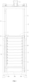
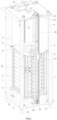
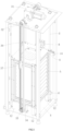
- a preferred embodiment of a die cutter supply system of the present invention includes a frame 1 and a die cutter storage rack 2 and a drive device 3 disposed within the frame 1.
- An exit-entry portion 4 for die cutters A to enter and exit the storage rack 2 is disposed at back and front sides of the frame 1 respectively.
- the exit-entry portion 4 at one side is used to connect with a high-speed smart cutting and processing center to provide a desired die cutter A for the high-speed smart cutting and processing center.
- the exit-entry portion 4 at the other side is used to change and sequentially configure the die cutters A in the frame 1.
- a plurality of die cutters A are stacked up and down in different layers in the storage rack 2.
- Guide columns 5 are respectively disposed at four corners of the frame 1.
- Guide sleeves 6 slidably cooperating with the guide columns 5 are disposed on the storage rack 2.
- the drive device 3 drives the storage rack 2 up and down along the guide columns 5.
- the drive device includes a motor gear box 31 provided with a dual output shaft, driving belt wheels 32, a driven shaft 33, driven bearings 34, driven belt wheels 35 and synchronous belts 36.
- the motor gear box 31 is disposed on the top of the frame 1.
- Two driving belt wheels 32 are respectively disposed on both ends of the output shaft.
- Two driven bearings 34 are fixed at a lower portion of the frame 1 and located below the storage rack 2.
- the driven shaft 33 is penetrated through the two driven bearings 34, and the driven belt wheels 35 are disposed on both ends of the driven shaft 33.
- the driving belt wheels 32 drive the driven belt wheels 35 to rotate by the synchronous belts 36.
- a synchronous belt 36 is disposed on left and right sides of the frame 1 respectively, and each synchronous belt 36 is provided with a cutter rack fixing plate 37, one end of the cutter rack fixing plate 37 is fixed on the synchronous belt 36, and the other end is fixed on the storage rack 2 at this side.
- the two synchronous belts 36 drive the storage rack 2 to move up and down along the guide columns 5 through respective cutter rack fixing plates 37 at the same time.
- the structure of the drive device 3 is simplified and the repeatability of the up and down moving position of the storage rack 2 is improved, thereby increasing the running stability.
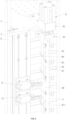
- a plurality of slideways 7 for placing the die cutters A are disposed at the left and right sides of the storage rack 2 respectively and a die cutter locking device 8 for positioning the die cutters A in the slideways 7 is disposed at the right side of the storage rack 2.
- the die cutter locking device 8 includes a locking cylinder 81, a locking operation rod 82, locking bearings 83, driving rods 84, locking rods 85, locking rod rotary shafts 86, and a rotary shaft fixing rod 87.
- the locking cylinder 81, the locking bearing 83, and the rotary shaft fixing rod 87 are respectively fixed to the storage rack 2.
- the locking cylinder 81 is fixed on an upper portion of the storage rack 2, and the locking operation rod 82 is fixedly connected with an output shaft of the locking cylinder 81.
- the locking operation rod 82 is penetrated through two locking bearings 83 which are fixed on the storage rack 2 and respectively located both ends of the locking operation rod 82.
- the locking operation rod 82 is slid up and down along the locking bearings 83 under the drive of the locking cylinder 81.
- the rotary shaft fixing rod 87 is fixed at a side of the storage rack 2, and the rotary shaft fixing rod 87 is provided with a plurality of avoiding holes 871 each corresponding to a placement position of the each layer of die cutter A.
- the driving rods 84, the locking rods 85 and the locking rod rotary shafts 86 are disposed at a side of the placement position of each layer of die cutter A respectively by sets.
- the locking rod is provided with a waist-shaped hole 851, a rotary shaft hole 852 and an arc-shaped portion 853 respectively, where the waist-shaped hole 851 and the arc-shaped portion 853 are located at both sides of the rotary shaft hole 852.
- the locking rod rotary shafts 86 are penetrated through the rotary shaft fixing rod 87 and the rotary shaft holes 852 of the locking rods 85 to movably connect the locking rods 85 in the locking rod avoiding holes 871 such that the locking rods 85 can rotate around the locking rod rotary shafts 86.
- One end of the driving rods 84 is fixed on the locking rods 85, and the other end is movable inserted into the waist-shaped holes of the locking rods 85.
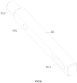
- the arc-shaped portions 853 of the locking rods 85 are fitted into limiting grooves B of side edges of the die cutters A, as shown in FIG. 5 .
- the locking operation rod 82 slides up and down and thus drives the locking rods 85 to rotate around the locking rod rotary shafts 86 through the driving rods 84, such that the arc-shaped portions 853 of the locking rods 85 are fitted into the limiting grooves B of the die cutters A so as to lock up the die cutters A, or the arc-shaped portions 853 of the locking rods 85 are released from the limiting grooves B of the die cutters A so as to unlock the die cutters A.
- the locking operation rod 82 is provided with a contact block 88, and an upper travel switch 10 and a lower travel switch 11 cooperating with the contact block 88 are respectively disposed on the frame 1.
- the contact block 88 moves up and down along with the locking operation rod 82 to trigger the upper travel switch 10 and the lower travel switch 11 respectively so as to limit the upper and lower positions for the movement of the locking operation rod 82, thereby improving the operation safety of the die cutter locking device 8.
- a roller 9 is disposed at a sidewall of each slideway 7.
- the rollers 9 are located above the die cutters A and close to the exit-entry portion 4 at the back of the frame 1, so as to achieve limiting and guiding effect when the die cutters A are guided into or out of the storage rack 2.
- a cutter rack support column 12 is disposed at the bottom of the storage rack 2 and fixed on the frame 1.
- a cutter rack limiting column 13 is disposed on the top of the frame 1. In this embodiment, four cutter rack support columns 12 are disposed correspondingly at four corners of the bottom of the storage rack 2, and four cutter rack limiting columns 13 are disposed correspondingly at four corners of the top of the frame 1. In this way, the safety and stability of the storage rack 2 can be improved.
- a stop switch 14 triggered by the storage rack 2 is disposed on the frame 1. The stop switch 14 is used to limit a descending position of the storage rack 2, thereby improving the movement safety and stability of the storage rack 2.
- the present invention is achieved by providing a high-speed smart cutting and processing center.
- the high-speed smart cutting and processing center uses the above die cutter supply system.
- the die cutter supply system can automatically provide the die cutters A desired for cutting operation to the high-speed smart cutting and processing center.
Landscapes
- Engineering & Computer Science (AREA)
- Mechanical Engineering (AREA)
- Life Sciences & Earth Sciences (AREA)
- Forests & Forestry (AREA)
- Perforating, Stamping-Out Or Severing By Means Other Than Cutting (AREA)
Description
- The present invention relates to the technical field of automatic cutting machines, and in particular to a die cutter supply system and a high-speed smart cutting and processing center using the system.
- The die cutters of the existing cutting machines are usually fixed mounted on the heads of the cutting machines and the die cutters need to be replaced manually each time the die cutters are to be changed to another model. This requires huge workload as well as position and angle debugging following each change of the die cutters, leading to much time wastes and low production efficiency as well as uncontrolled quality. Although some cutting machines adopt automatic die cutter change technology, these cutting machines are complex in structure, large in volume, huge in land occupation area, high in failure rate and poor in running stability.
CN 107 097 294 A discloses a cutting machine for sheet cutting which comprises a die cutting head, a cutting die replacement mechanism, a tool magazine, a rack, a bracket and a control box. The die cutting head is arranged on the rack which is arranged at one end of the die cutting head. The tool magazine is arranged in the bracket. The cutting die replacement mechanism is arranged between the tool magazine and the die cutting head. A cutting die is arranged under the die cutting head, and the control box is arranged on the rack.CN 201 231 508 Y discloses a foam board cutting machine. - In order to address the above technical problems, the present invention provides a die cutter supply system and a high-speed smart cutting and processing center using the system, which feature simple structure, small volume and good stability.
- The present invention is achieved by providing a die cutter supply system, which includes a frame and a die cutter storage rack and a drive device disposed within the frame. An exit-entry portion for die cutters to enter and exit the storage rack is disposed at back and front sides of the frame respectively. A plurality of die cutters are stacked up and down in different layers in the storage rack. Guide columns are respectively disposed at four corners of the frame, and guide sleeves slidable cooperating with the guide columns are disposed on the storage rack. The drive device drives the storage rack up and down along the guide columns. The drive device includes a motor gear box provided with a dual-output shaft, driving belt wheels, a driven shaft, driven bearings, driven belt wheels and synchronous belts. The motor gear box is disposed on the top of the frame. Two driving belt wheels are respectively disposed on both ends of the output shaft. Two driven bearings are fixed at a lower portion of the frame and located below the storage rack. The driven shaft is penetrated through the two driven bearings, and the driven belt wheels are disposed on both ends of the driven shaft. The driving belt wheels drive the driven belt wheels to rotate by the synchronous belts. A synchronous belt is disposed on left and right sides of the frame respectively, and each synchronous belt is provided with a cutter rack fixing plate. One end of the cutter rack fixing plate is fixed on the synchronous belt, and the other end is fixed on the storage rack at this side.
- According to present invention, a plurality of slideways for placing die cutters are disposed up and down at right and left sides of the storage rack respectively. A die cutter locking device for positioning a die cutter in a slideway is disposed at the right side of the storage rack. The die cutter locking device includes a locking cylinder, a locking operation rod, locking bearings, driving rods, locking rods, locking rod rotary shafts, and a rotary shaft fixing rod. The locking cylinder is fixed on an upper portion of the storage rack, and the locking operation rod is fixedly connected with an output shaft of the locking cylinder. The locking operation rod is penetrated through two locking bearings, and the two locking bearings are fixed on the storage rack and respectively located at both ends of the locking operation rod. The locking operation rod is slid up and down along the locking bearings under the drive of the locking cylinder. The rotary shaft fixing rod is fixed at a side of the storage rack, and the rotary shaft fixing rod is provided with a plurality of avoiding holes corresponding to a placement position of each layer of die cutter. The driving rods, the locking rods and the locking rod rotary shafts are respectively disposed at a side of the placement position of each layer of die cutter by sets. The locking rods are provided with a waist-shaped hole, a rotary shaft hole, and an arc-shaped portion. The locking rod rotary shafts are penetrated through the rotary shaft fixing rod and the rotary shaft holes of the locking rods to movably connect the locking rods in the avoiding holes of the locking rods. One end of the driving rods is fixed on the locking rods, and the other end is movably inserted into the waist-shaped holes of the locking rods. The arc-shaped portions of the locking rods are fitted into limiting grooves of side edges of the die cutters. The locking operation rod slides up and down and thus drives the locking rods to rotate around the locking rod rotary shafts through the driving rods.
- Optionally, a roller is disposed at a sidewall of each
slideway 7. - Optionally, the locking operation rod is provided with a contact block, and an upper travel switch and a lower travel switch cooperating with the contact block are respectively disposed on the frame.
- Optionally, a cutter rack support column is disposed at the bottom of the storage rack, and a cutter rack limiting column is disposed on the top of the
frame 1. - Optionally, a stop switch triggered by the storage rack is disposed on the frame.
- The present invention is achieved by providing a high-speed smart cutting and processing center. The high-speed smart cutting and processing center uses the above die cutter supply system.
- Compared with the prior arts, in the die cuter supply system and the high-speed smart cutting and processing center using the system in the present invention, the die cutter supply system includes a die cutter storage rack and a drive device disposed within the frame; the die cutters are stacked up and down in different layers in the storage rack; the guide columns are respectively disposed at four corners of the frame; guide sleeves slidable cooperating with the guide columns are disposed on the storage rack; the drive device drives the storage rack to move up and down along the guide columns; the drive device includes synchronous belts disposed at the right and left sides of the frame, and each synchronous belt is provided with a cutter rack fixing plate, one end of which is fixed to the synchronous belt and the other end is fixed to the storage rack at this side; the two synchronous belts drive the storage rack to move up and down through respective cutter rack fixing plates at the same time. With the synchronous belt structure, the drive structure is simplified, and the device volume is effectively reduced, and further the repeatability of the up and down moving position of the die cutter storage rack is improved, thereby ensuring good device stability. On the other hand, the present invention facilitates change of die cutters, which not only shortens the change time but also increases the working efficiency. Further, accurate positioning can be achieved so as to improve the cutting accuracy of the high-speed smart cutting and processing center.
-
-
FIG. 1 is a front view of a preferred embodiment of a die cutter supply system in the present invention. -
FIG. 2 is a stereoscopic schematic diagram ofFIG. 1 . -
FIG. 3 is a stereoscopic schematic diagram ofFIG. 2 from another perspective. -
FIG. 4 is a partially-enlarged view of an M part inFIG. 2 . -
FIG. 5 is a stereoscopic schematic diagram of a die cutter inFIG. 2 . -
FIG. 6 is a stereoscopic schematic diagram of a locking rod inFIG. 2 . - In order to make the technical problems, the technical solutions and the beneficial effects clearer and more intelligible, the present invention will be further elaborated in combination with accompanying drawings and specific embodiments. It should be understood that the specific embodiments described herein are used only to explain the present invention rather than limit the present invention.
- By referring
FIGS. 1 to 4 at the same time, a preferred embodiment of a die cutter supply system of the present invention includes aframe 1 and a diecutter storage rack 2 and adrive device 3 disposed within theframe 1. - An exit-
entry portion 4 for die cutters A to enter and exit thestorage rack 2 is disposed at back and front sides of theframe 1 respectively. The exit-entry portion 4 at one side is used to connect with a high-speed smart cutting and processing center to provide a desired die cutter A for the high-speed smart cutting and processing center. The exit-entry portion 4 at the other side is used to change and sequentially configure the die cutters A in theframe 1. A plurality of die cutters A are stacked up and down in different layers in thestorage rack 2.Guide columns 5 are respectively disposed at four corners of theframe 1.Guide sleeves 6 slidably cooperating with theguide columns 5 are disposed on thestorage rack 2. Thedrive device 3 drives thestorage rack 2 up and down along theguide columns 5. - The drive device includes a
motor gear box 31 provided with a dual output shaft, drivingbelt wheels 32, a drivenshaft 33, drivenbearings 34, drivenbelt wheels 35 andsynchronous belts 36. Themotor gear box 31 is disposed on the top of theframe 1. Two drivingbelt wheels 32 are respectively disposed on both ends of the output shaft. Two drivenbearings 34 are fixed at a lower portion of theframe 1 and located below thestorage rack 2. The drivenshaft 33 is penetrated through the two drivenbearings 34, and the drivenbelt wheels 35 are disposed on both ends of the drivenshaft 33. The drivingbelt wheels 32 drive the drivenbelt wheels 35 to rotate by thesynchronous belts 36. Asynchronous belt 36 is disposed on left and right sides of theframe 1 respectively, and eachsynchronous belt 36 is provided with a cutterrack fixing plate 37, one end of the cutterrack fixing plate 37 is fixed on thesynchronous belt 36, and the other end is fixed on thestorage rack 2 at this side. The twosynchronous belts 36 drive thestorage rack 2 to move up and down along theguide columns 5 through respective cutterrack fixing plates 37 at the same time. With the synchronous belt technology, the structure of thedrive device 3 is simplified and the repeatability of the up and down moving position of thestorage rack 2 is improved, thereby increasing the running stability. - A plurality of
slideways 7 for placing the die cutters A are disposed at the left and right sides of thestorage rack 2 respectively and a diecutter locking device 8 for positioning the die cutters A in theslideways 7 is disposed at the right side of thestorage rack 2. - The die
cutter locking device 8 includes alocking cylinder 81, a lockingoperation rod 82, lockingbearings 83, drivingrods 84, lockingrods 85, lockingrod rotary shafts 86, and a rotaryshaft fixing rod 87. The lockingcylinder 81, the lockingbearing 83, and the rotaryshaft fixing rod 87 are respectively fixed to thestorage rack 2. - The locking
cylinder 81 is fixed on an upper portion of thestorage rack 2, and the lockingoperation rod 82 is fixedly connected with an output shaft of the lockingcylinder 81. The lockingoperation rod 82 is penetrated through two lockingbearings 83 which are fixed on thestorage rack 2 and respectively located both ends of the lockingoperation rod 82. The lockingoperation rod 82 is slid up and down along the lockingbearings 83 under the drive of the lockingcylinder 81. The rotaryshaft fixing rod 87 is fixed at a side of thestorage rack 2, and the rotaryshaft fixing rod 87 is provided with a plurality of avoidingholes 871 each corresponding to a placement position of the each layer of die cutter A. - The driving
rods 84, the lockingrods 85 and the lockingrod rotary shafts 86 are disposed at a side of the placement position of each layer of die cutter A respectively by sets. As shown inFIG. 6 , the locking rod is provided with a waist-shapedhole 851, arotary shaft hole 852 and an arc-shapedportion 853 respectively, where the waist-shapedhole 851 and the arc-shapedportion 853 are located at both sides of therotary shaft hole 852. The lockingrod rotary shafts 86 are penetrated through the rotaryshaft fixing rod 87 and the rotary shaft holes 852 of the lockingrods 85 to movably connect the lockingrods 85 in the lockingrod avoiding holes 871 such that the lockingrods 85 can rotate around the lockingrod rotary shafts 86. One end of the drivingrods 84 is fixed on the lockingrods 85, and the other end is movable inserted into the waist-shaped holes of the lockingrods 85. The arc-shapedportions 853 of the lockingrods 85 are fitted into limiting grooves B of side edges of the die cutters A, as shown inFIG. 5 . - The locking
operation rod 82 slides up and down and thus drives the lockingrods 85 to rotate around the lockingrod rotary shafts 86 through the drivingrods 84, such that the arc-shapedportions 853 of the lockingrods 85 are fitted into the limiting grooves B of the die cutters A so as to lock up the die cutters A, or the arc-shapedportions 853 of the lockingrods 85 are released from the limiting grooves B of the die cutters A so as to unlock the die cutters A. - The locking
operation rod 82 is provided with acontact block 88, and an upper travel switch 10 and alower travel switch 11 cooperating with thecontact block 88 are respectively disposed on theframe 1. Thecontact block 88 moves up and down along with the lockingoperation rod 82 to trigger the upper travel switch 10 and thelower travel switch 11 respectively so as to limit the upper and lower positions for the movement of the lockingoperation rod 82, thereby improving the operation safety of the diecutter locking device 8. - With the locking
cylinder 81 as power, the response time of the diecutter locking device 8 can be shortened and the working efficiency of the die cutter supply system can be improved. - A
roller 9 is disposed at a sidewall of eachslideway 7. Therollers 9 are located above the die cutters A and close to the exit-entry portion 4 at the back of theframe 1, so as to achieve limiting and guiding effect when the die cutters A are guided into or out of thestorage rack 2. A cutterrack support column 12 is disposed at the bottom of thestorage rack 2 and fixed on theframe 1. A cutterrack limiting column 13 is disposed on the top of theframe 1. In this embodiment, four cutterrack support columns 12 are disposed correspondingly at four corners of the bottom of thestorage rack 2, and four cutterrack limiting columns 13 are disposed correspondingly at four corners of the top of theframe 1. In this way, the safety and stability of thestorage rack 2 can be improved. Astop switch 14 triggered by thestorage rack 2 is disposed on theframe 1. Thestop switch 14 is used to limit a descending position of thestorage rack 2, thereby improving the movement safety and stability of thestorage rack 2. - The present invention is achieved by providing a high-speed smart cutting and processing center. The high-speed smart cutting and processing center uses the above die cutter supply system. The die cutter supply system can automatically provide the die cutters A desired for cutting operation to the high-speed smart cutting and processing center.
- The above descriptions are made only to preferred embodiments of the present invention and are not used to limit the present invention, which is defined by the claims.
Claims (6)
- A die cutter supply system, comprising: a frame (1) and a die cutter storage rack (2) and a drive device (3) disposed within the frame (1), wherein an exit-entry portion (4) for die cutters (A) to enter and exit the storage rack (2) are disposed at back and front sides of the frame (1) respectively, a plurality of die cutters (A) are stacked up and down in different layers in the storage rack (2), guide columns (5) are respectively disposed at four corners of the frame (1), guide sleeves (6) slidably cooperating with the guide columns (5) are disposed on the storage rack (2), and the drive device (3) drives the storage rack (2) up and down along the guide columns (5); characterised in that the drive device (3) comprises a motor gear box (31) provided with a dual output shaft, driving belt wheels (32), a driven shaft (33), driven bearings (34), driven belt wheels (35) and synchronous belts (36), the motor gear box (31) is disposed on the top of the frame (1), two driving belt wheels (32) are respectively disposed on both ends of the output shaft, two driven bearings (34) are fixed at a lower portion of the frame (1) and located below the storage rack (2), the driven shaft (33) is penetrated through the two driven bearings (34), the driven belt wheels (35) are disposed on both ends of the driven shaft (33), the driving belt wheels (32) drive the driven belt wheels (35) to rotate by the synchronous belts (36), a synchronous belt (36) is disposed on left and right sides of the frame (1) respectively, each synchronous belt (36) is provided with a cutter rack fixing plate (37), one end of the cutter rack fixing plate (37) is fixed on the synchronous belt (36), and the other end is fixed on the storage rack (2) at this side,
wherein a plurality of slideways (7) for placing die cutters (A) are disposed up and down at right and left sides of the storage rack (2) respectively, a die cutter locking device (8) for positioning a die cutter (A) in a slideway (7) is disposed at the right side of the storage rack (2), the die cutter locking device (8) comprises a locking cylinder (81), a locking operation rod (82), locking bearings (83), driving rods (84), locking rods (85), locking rod rotary shafts (86), and rotary shaft fixing rods (87), the locking cylinder (81) is fixed on an upper portion of the storage rack (2), the locking operation rod (82) is fixedly connected with an output shaft of the locking cylinder (81), the locking operation rod (82) is penetrated through two locking bearings (83), the two locking bearings (83) are fixed on the storage rack (2) and respectively located at both ends of the locking operation rod (82), the locking operation rod (82) is slid up and down along the locking bearings (83) under the drive of the locking cylinder (81), the rotary shaft fixing rod (87) is fixed at a side of the storage rack (2), the rotary shaft fixing rod (87) is provided with a plurality of avoiding holes (871) corresponding to a placement position of each layer of die cutter (A), the driving rods (84), the locking rods (85) and the locking rod rotary shafts (86) are respectively disposed at a side of the placement position of each layer of die cutter (A) by sets, the locking rods (85) are provided with a waist-shaped hole (851), a rotary shaft hole (852), and an arc-shaped portion (853), the locking rod rotary shafts (86) are penetrated through the rotary shaft fixing rod (87) and the rotary shaft holes (852) of the locking rods (85) to movably connect the locking rods (85) in the avoiding hole (871) of the locking rods (85), one end of the driving rods (84) is fixed on the locking rods (85), the other end is movably inserted into the waist-shaped holes (851) of the locking rods (85), the arc-shaped portion (853) of the locking rods (85) is fitted into limiting grooves (B) of side edges of the die cutters (A) and the locking operation rod (82) slides up and down and thus drives the locking rods (85) to rotate around the locking rod rotary shafts (86) through the driving rods (84). - The die cutter supply system of claim 1, wherein a roller (9) is disposed at a sidewall of each slideway (7).
- The die cutter supply system of claim 1, wherein the locking operation rod (82) is provided with a contact block (88), and an upper travel switch (10) and a lower travel switch (11) cooperating with the contact block (88) are respectively disposed on the frame (1).
- The die cutter supply system of claim 1, wherein a cutter rack support column (12) is disposed at the bottom of the storage rack (2), and a cutter rack limiting column (13) is disposed on the top of the frame (1).
- The die cutter supply system of claim 1, wherein a stop switch (14) triggered by the storage rack (2) is disposed on the frame (1).
- A high-speed smart cutting and processing center, using the die cutter supply system of any one of claims 1 to 4.
Applications Claiming Priority (2)
| Application Number | Priority Date | Filing Date | Title |
|---|---|---|---|
| CN202110567905.7A CN113146724B (en) | 2021-05-24 | 2021-05-24 | Cutting die supply system and high-speed intelligent cutting machining center using same |
| PCT/CN2021/138070 WO2022247236A1 (en) | 2021-05-24 | 2021-12-14 | Knife die supply system and high-speed intelligent cutting processing center using same |
Publications (4)
| Publication Number | Publication Date |
|---|---|
| EP4201616A1 EP4201616A1 (en) | 2023-06-28 |
| EP4201616A4 EP4201616A4 (en) | 2024-05-29 |
| EP4201616C0 EP4201616C0 (en) | 2025-01-29 |
| EP4201616B1 true EP4201616B1 (en) | 2025-01-29 |
Family
ID=76877222
Family Applications (1)
| Application Number | Title | Priority Date | Filing Date |
|---|---|---|---|
| EP21942799.4A Active EP4201616B1 (en) | 2021-05-24 | 2021-12-14 | Die cutter supply system |
Country Status (3)
| Country | Link |
|---|---|
| EP (1) | EP4201616B1 (en) |
| CN (1) | CN113146724B (en) |
| WO (1) | WO2022247236A1 (en) |
Families Citing this family (1)
| Publication number | Priority date | Publication date | Assignee | Title |
|---|---|---|---|---|
| CN113146724B (en) * | 2021-05-24 | 2025-09-19 | 衢州台威精工机械有限公司 | Cutting die supply system and high-speed intelligent cutting machining center using same |
Family Cites Families (17)
| Publication number | Priority date | Publication date | Assignee | Title |
|---|---|---|---|---|
| JP3515952B2 (en) * | 2000-11-22 | 2004-04-05 | 株式会社協和製作所 | Slitter blade changing device and blade changing method |
| CN201231508Y (en) * | 2008-07-22 | 2009-05-06 | 武炳太 | Foam board cutter |
| CN204640345U (en) * | 2015-05-18 | 2015-09-16 | 瑞安市中泰科技设备有限公司 | The knife plate fast assembling and disassembling device of die-cutting machine |
| CN106926316B (en) * | 2017-04-10 | 2018-05-25 | 盐城市华森机械有限公司 | A kind of sheet material cuts efficient guillotine |
| CN207077527U (en) * | 2017-04-10 | 2018-03-09 | 盐城市华森机械有限公司 | A kind of sheet material cuts efficient guillotine |
| CN107097294A (en) * | 2017-06-19 | 2017-08-29 | 盐城市华森机械有限公司 | A kind of sheet material cuts efficient guillotine |
| CN107775725B (en) * | 2017-11-16 | 2023-07-18 | 瑞安市奥尔印刷包装机械有限公司 | Die cutting machine |
| CN108384904A (en) * | 2018-05-30 | 2018-08-10 | 盐城市裕正精密机械有限公司 | Full-automatic leather cutting machine |
| JP7112724B2 (en) * | 2018-08-07 | 2022-08-04 | 京都機械工具株式会社 | tool shelf |
| CN209793905U (en) * | 2019-01-28 | 2019-12-17 | 温州永裕智能科技有限公司 | automatic tool changing type cutting machine |
| CN109822664A (en) * | 2019-01-28 | 2019-05-31 | 温州永裕智能科技有限公司 | A kind of automatic tool changer for cutting machine |
| CN212525693U (en) * | 2019-12-06 | 2021-02-12 | 盐城市裕正精密机械有限公司 | Cutting machine cutting die storehouse structure |
| CN112297115A (en) * | 2020-11-05 | 2021-02-02 | 东莞市陆陆兴工业自动化科技有限公司 | Automatic tool changing cutting machine |
| CN113146724B (en) * | 2021-05-24 | 2025-09-19 | 衢州台威精工机械有限公司 | Cutting die supply system and high-speed intelligent cutting machining center using same |
| CN215511311U (en) * | 2021-05-24 | 2022-01-14 | 衢州台威精工机械有限公司 | A high-speed intelligent cutting and machining center |
| CN214686868U (en) * | 2021-05-24 | 2021-11-12 | 衢州台威精工机械有限公司 | Die supply system and high-speed intelligent cutting and machining center using the system |
| CN113134863B (en) * | 2021-05-24 | 2024-02-27 | 衢州台威精工机械有限公司 | High-speed intelligent cutting machining center and method for replacing cutter template |
-
2021
- 2021-05-24 CN CN202110567905.7A patent/CN113146724B/en active Active
- 2021-12-14 EP EP21942799.4A patent/EP4201616B1/en active Active
- 2021-12-14 WO PCT/CN2021/138070 patent/WO2022247236A1/en not_active Ceased
Also Published As
| Publication number | Publication date |
|---|---|
| EP4201616A1 (en) | 2023-06-28 |
| CN113146724B (en) | 2025-09-19 |
| EP4201616C0 (en) | 2025-01-29 |
| EP4201616A4 (en) | 2024-05-29 |
| CN113146724A (en) | 2021-07-23 |
| WO2022247236A1 (en) | 2022-12-01 |
Similar Documents
| Publication | Publication Date | Title |
|---|---|---|
| EP4201614B1 (en) | High-speed intelligent cutting machining center and method for replacing knife die plates | |
| CN112720715B (en) | Numerical control side drilling machine | |
| CN219336428U (en) | Stable laser cutting machine cuts | |
| EP4201616B1 (en) | Die cutter supply system | |
| CN113001223A (en) | Full-automatic cutting machine with tool changing structure of straight-line tool magazine | |
| CN215511311U (en) | A high-speed intelligent cutting and machining center | |
| CN214686868U (en) | Die supply system and high-speed intelligent cutting and machining center using the system | |
| CN219652361U (en) | Novel copper strips is cut device | |
| CN209453227U (en) | The charging and discharging mechanism of cut edge equipment | |
| CN208840893U (en) | A kind of double sides milling machine | |
| CN217915474U (en) | Cutting device is used in label paper production | |
| CN111715932A (en) | Plate flying shear | |
| CN216882016U (en) | Plastic-aluminum section bar saw cuts machining center | |
| CN212526270U (en) | Plate flying shear | |
| CN214293572U (en) | Intelligent full-automatic numerical control grooving machine | |
| CN221454647U (en) | Material clamping device of H-shaped steel laser cutting machine | |
| CN220008054U (en) | Splitting machine | |
| CN221517009U (en) | Automatic tool changing engraving and milling machine | |
| CN222712242U (en) | A stamping equipment for seat lock lower cover | |
| CN221028498U (en) | Automatic cowhide roll cutting machine with correction function | |
| CN221362885U (en) | Edge cutting device for strip machining | |
| CN222842875U (en) | Bending machine with automatic blade splitting structure | |
| CN220882530U (en) | Paper cutter with protection machanism | |
| CN221517937U (en) | Paper cutting equipment for printing | |
| CN223701062U (en) | Foam slitting machine |
Legal Events
| Date | Code | Title | Description |
|---|---|---|---|
| STAA | Information on the status of an ep patent application or granted ep patent |
Free format text: STATUS: THE INTERNATIONAL PUBLICATION HAS BEEN MADE |
|
| PUAI | Public reference made under article 153(3) epc to a published international application that has entered the european phase |
Free format text: ORIGINAL CODE: 0009012 |
|
| STAA | Information on the status of an ep patent application or granted ep patent |
Free format text: STATUS: REQUEST FOR EXAMINATION WAS MADE |
|
| 17P | Request for examination filed |
Effective date: 20230321 |
|
| AK | Designated contracting states |
Kind code of ref document: A1 Designated state(s): AL AT BE BG CH CY CZ DE DK EE ES FI FR GB GR HR HU IE IS IT LI LT LU LV MC MK MT NL NO PL PT RO RS SE SI SK SM TR |
|
| A4 | Supplementary search report drawn up and despatched |
Effective date: 20240425 |
|
| RIC1 | Information provided on ipc code assigned before grant |
Ipc: B26F 1/44 20060101ALI20240419BHEP Ipc: B26D 5/00 20060101ALI20240419BHEP Ipc: B26F 1/40 20060101ALI20240419BHEP Ipc: B26D 7/26 20060101AFI20240419BHEP |
|
| DAV | Request for validation of the european patent (deleted) | ||
| DAX | Request for extension of the european patent (deleted) | ||
| GRAP | Despatch of communication of intention to grant a patent |
Free format text: ORIGINAL CODE: EPIDOSNIGR1 |
|
| STAA | Information on the status of an ep patent application or granted ep patent |
Free format text: STATUS: GRANT OF PATENT IS INTENDED |
|
| GRAS | Grant fee paid |
Free format text: ORIGINAL CODE: EPIDOSNIGR3 |
|
| GRAA | (expected) grant |
Free format text: ORIGINAL CODE: 0009210 |
|
| STAA | Information on the status of an ep patent application or granted ep patent |
Free format text: STATUS: THE PATENT HAS BEEN GRANTED |
|
| INTG | Intention to grant announced |
Effective date: 20241127 |
|
| AK | Designated contracting states |
Kind code of ref document: B1 Designated state(s): AL AT BE BG CH CY CZ DE DK EE ES FI FR GB GR HR HU IE IS IT LI LT LU LV MC MK MT NL NO PL PT RO RS SE SI SK SM TR |
|
| REG | Reference to a national code |
Ref country code: GB Ref legal event code: FG4D |
|
| REG | Reference to a national code |
Ref country code: CH Ref legal event code: EP |
|
| REG | Reference to a national code |
Ref country code: DE Ref legal event code: R096 Ref document number: 602021025722 Country of ref document: DE |
|
| REG | Reference to a national code |
Ref country code: IE Ref legal event code: FG4D |
|
| U01 | Request for unitary effect filed |
Effective date: 20250225 |
|
| U07 | Unitary effect registered |
Designated state(s): AT BE BG DE DK EE FI FR IT LT LU LV MT NL PT RO SE SI Effective date: 20250303 |
|
| PG25 | Lapsed in a contracting state [announced via postgrant information from national office to epo] |
Ref country code: RS Free format text: LAPSE BECAUSE OF FAILURE TO SUBMIT A TRANSLATION OF THE DESCRIPTION OR TO PAY THE FEE WITHIN THE PRESCRIBED TIME-LIMIT Effective date: 20250429 |
|
| PG25 | Lapsed in a contracting state [announced via postgrant information from national office to epo] |
Ref country code: PL Free format text: LAPSE BECAUSE OF FAILURE TO SUBMIT A TRANSLATION OF THE DESCRIPTION OR TO PAY THE FEE WITHIN THE PRESCRIBED TIME-LIMIT Effective date: 20250129 |
|
| PG25 | Lapsed in a contracting state [announced via postgrant information from national office to epo] |
Ref country code: ES Free format text: LAPSE BECAUSE OF FAILURE TO SUBMIT A TRANSLATION OF THE DESCRIPTION OR TO PAY THE FEE WITHIN THE PRESCRIBED TIME-LIMIT Effective date: 20250129 |
|
| PG25 | Lapsed in a contracting state [announced via postgrant information from national office to epo] |
Ref country code: IS Free format text: LAPSE BECAUSE OF FAILURE TO SUBMIT A TRANSLATION OF THE DESCRIPTION OR TO PAY THE FEE WITHIN THE PRESCRIBED TIME-LIMIT Effective date: 20250529 Ref country code: NO Free format text: LAPSE BECAUSE OF FAILURE TO SUBMIT A TRANSLATION OF THE DESCRIPTION OR TO PAY THE FEE WITHIN THE PRESCRIBED TIME-LIMIT Effective date: 20250429 |
|
| PG25 | Lapsed in a contracting state [announced via postgrant information from national office to epo] |
Ref country code: HR Free format text: LAPSE BECAUSE OF FAILURE TO SUBMIT A TRANSLATION OF THE DESCRIPTION OR TO PAY THE FEE WITHIN THE PRESCRIBED TIME-LIMIT Effective date: 20250129 |
|
| PG25 | Lapsed in a contracting state [announced via postgrant information from national office to epo] |
Ref country code: GR Free format text: LAPSE BECAUSE OF FAILURE TO SUBMIT A TRANSLATION OF THE DESCRIPTION OR TO PAY THE FEE WITHIN THE PRESCRIBED TIME-LIMIT Effective date: 20250430 |
|
| PG25 | Lapsed in a contracting state [announced via postgrant information from national office to epo] |
Ref country code: SM Free format text: LAPSE BECAUSE OF FAILURE TO SUBMIT A TRANSLATION OF THE DESCRIPTION OR TO PAY THE FEE WITHIN THE PRESCRIBED TIME-LIMIT Effective date: 20250129 |
|
| PG25 | Lapsed in a contracting state [announced via postgrant information from national office to epo] |
Ref country code: CZ Free format text: LAPSE BECAUSE OF FAILURE TO SUBMIT A TRANSLATION OF THE DESCRIPTION OR TO PAY THE FEE WITHIN THE PRESCRIBED TIME-LIMIT Effective date: 20250129 |
|
| PG25 | Lapsed in a contracting state [announced via postgrant information from national office to epo] |
Ref country code: SK Free format text: LAPSE BECAUSE OF FAILURE TO SUBMIT A TRANSLATION OF THE DESCRIPTION OR TO PAY THE FEE WITHIN THE PRESCRIBED TIME-LIMIT Effective date: 20250129 |
|
| PLBE | No opposition filed within time limit |
Free format text: ORIGINAL CODE: 0009261 |
|
| STAA | Information on the status of an ep patent application or granted ep patent |
Free format text: STATUS: NO OPPOSITION FILED WITHIN TIME LIMIT |
|
| U20 | Renewal fee for the european patent with unitary effect paid |
Year of fee payment: 5 Effective date: 20251105 |
|
| 26N | No opposition filed |
Effective date: 20251030 |