EP4201614B1 - Centre d'usinage par coupe intelligent à grande vitesse et procédé de remplacement de plateaux matrices à lame - Google Patents
Centre d'usinage par coupe intelligent à grande vitesse et procédé de remplacement de plateaux matrices à lame Download PDFInfo
- Publication number
- EP4201614B1 EP4201614B1 EP21942800.0A EP21942800A EP4201614B1 EP 4201614 B1 EP4201614 B1 EP 4201614B1 EP 21942800 A EP21942800 A EP 21942800A EP 4201614 B1 EP4201614 B1 EP 4201614B1
- Authority
- EP
- European Patent Office
- Prior art keywords
- die cutter
- die
- disposed
- plate
- locking
- Prior art date
- Legal status (The legal status is an assumption and is not a legal conclusion. Google has not performed a legal analysis and makes no representation as to the accuracy of the status listed.)
- Active
Links
Images


Classifications
-
- B—PERFORMING OPERATIONS; TRANSPORTING
- B26—HAND CUTTING TOOLS; CUTTING; SEVERING
- B26D—CUTTING; DETAILS COMMON TO MACHINES FOR PERFORATING, PUNCHING, CUTTING-OUT, STAMPING-OUT OR SEVERING
- B26D7/00—Details of apparatus for cutting, cutting-out, stamping-out, punching, perforating, or severing by means other than cutting
- B26D7/08—Means for treating work or cutting member to facilitate cutting
-
- B—PERFORMING OPERATIONS; TRANSPORTING
- B26—HAND CUTTING TOOLS; CUTTING; SEVERING
- B26D—CUTTING; DETAILS COMMON TO MACHINES FOR PERFORATING, PUNCHING, CUTTING-OUT, STAMPING-OUT OR SEVERING
- B26D5/00—Arrangements for operating and controlling machines or devices for cutting, cutting-out, stamping-out, punching, perforating, or severing by means other than cutting
-
- B—PERFORMING OPERATIONS; TRANSPORTING
- B25—HAND TOOLS; PORTABLE POWER-DRIVEN TOOLS; MANIPULATORS
- B25H—WORKSHOP EQUIPMENT, e.g. FOR MARKING-OUT WORK; STORAGE MEANS FOR WORKSHOPS
- B25H3/00—Storage means or arrangements for workshops facilitating access to, or handling of, work tools or instruments
-
- B—PERFORMING OPERATIONS; TRANSPORTING
- B26—HAND CUTTING TOOLS; CUTTING; SEVERING
- B26D—CUTTING; DETAILS COMMON TO MACHINES FOR PERFORATING, PUNCHING, CUTTING-OUT, STAMPING-OUT OR SEVERING
- B26D7/00—Details of apparatus for cutting, cutting-out, stamping-out, punching, perforating, or severing by means other than cutting
- B26D7/26—Means for mounting or adjusting the cutting member; Means for adjusting the stroke of the cutting member
- B26D7/2614—Means for mounting the cutting member
-
- B—PERFORMING OPERATIONS; TRANSPORTING
- B26—HAND CUTTING TOOLS; CUTTING; SEVERING
- B26F—PERFORATING; PUNCHING; CUTTING-OUT; STAMPING-OUT; SEVERING BY MEANS OTHER THAN CUTTING
- B26F1/00—Perforating; Punching; Cutting-out; Stamping-out; Apparatus therefor
- B26F1/38—Cutting-out; Stamping-out
-
- B—PERFORMING OPERATIONS; TRANSPORTING
- B26—HAND CUTTING TOOLS; CUTTING; SEVERING
- B26F—PERFORATING; PUNCHING; CUTTING-OUT; STAMPING-OUT; SEVERING BY MEANS OTHER THAN CUTTING
- B26F1/00—Perforating; Punching; Cutting-out; Stamping-out; Apparatus therefor
- B26F1/38—Cutting-out; Stamping-out
- B26F1/40—Cutting-out; Stamping-out using a press, e.g. of the ram type
- B26F1/405—Travelling head presses
-
- B—PERFORMING OPERATIONS; TRANSPORTING
- B26—HAND CUTTING TOOLS; CUTTING; SEVERING
- B26D—CUTTING; DETAILS COMMON TO MACHINES FOR PERFORATING, PUNCHING, CUTTING-OUT, STAMPING-OUT OR SEVERING
- B26D7/00—Details of apparatus for cutting, cutting-out, stamping-out, punching, perforating, or severing by means other than cutting
- B26D7/26—Means for mounting or adjusting the cutting member; Means for adjusting the stroke of the cutting member
- B26D2007/2607—Means for mounting or adjusting the cutting member; Means for adjusting the stroke of the cutting member for mounting die cutters
Definitions
- According to the present invention relates to the technical field of smart cutting equipment, and in particular to a high-speed smart cutting and processing center and a method of changing a die cutter.
- the cutting machines require frequent change of die cutters based on cutting patterns and the die cutters are usually disposed on the die cutter plates.
- die cutters are changed by hand, which leads to long time and low efficiency.
- the position repeatability of the changed die cutters is poor and the size accuracy of the cut products is low.
- the die cutters are changed by using a pinion and rack mechanism, which brings up the working efficient and reduces the workload.
- the die cutter changing mechanism has the following defects: 1. the die cutter changing mechanism is located at a side of the cutting machine, leading to large land occupation area, long transverse movement distance and structural instability; 2.
- the working panel needs to rotate 90° to enable the die cutter to be in transverse state, leading to complex structure and occurrence of failures; 3. the pinion and rack mechanism can generate large noise during operation and has the disadvantages of complex structure and troublesome repairs; 4. after change, the die cutter may have displacement during movement or rotation, leading to inaccurate processing position, and unstable product quality; 5. the running speed is low and the time for changing a die cutter is long.
- CN 107 097 294 A discloses a high-speed smart cutting and processing center, comprising a cutting machine, a die cutter magazine and a die cutter circulation table, wherein the cutting machine includes a machine base, a working table and a cross beam, where the working table and the cross beam are disposed on the machine base, punch slide rails are disposed on the cross beam, matching punch slide seats are disposed on the punch slide rails respectively, a rotary cutting head is disposed under the punch slide seats, a die cutter fixing plate is disposed at the bottom of the rotary cutting head, a die cutter for cutting and a die cutter clamping and limiting device are disposed at the bottom of the rotary cutting head, the die cutter circulation table is located at the left side of the working table, one end of the die cutter circulation table is connected with the die cutter magazine and the other end is connected with the working table, the die cutter magazine comprises a frame, a die cutter storage rack and a lifting device, where the die cutter storage rack and the lifting device are disposed within the frame, a plurality
- CN 106 734 503 A discloses an automatic tool die changing type special-shaped material blanking machine which comprises a punching head, a tool die changing mechanism, a rack and a control box.
- the punching head is arranged on the rack, and a tool die is arranged below the punching head.
- the tool die changing mechanism is arranged on one side of the punching head, the control box is arranged on the rack, and the tool die changing mechanism can be used for driving the tool die to move between the punching head and a tool die warehouse.
- CN 212 525 693 U discloses a cutter die library structure of a cutting machine, which comprises a cutter library frame, two sides of the front end of the cutter library frame are respectively fixed on a rack of the cutting machine through a fixing frame, vertical screw rods are symmetrically arranged on two sides of the rack, and the upper ends and the lower ends of the vertical screw rods are respectively and rotatably arranged on the cutter library frame through bearing seats.
- First driven chain wheels are arranged at the upper ends, extending out of the bearing seats, of the two vertical screws respectively, the two first driven chain wheels are connected through a driven chain, and a tensioning chain wheel adjusting frame is movably arranged at the position, between the two first driven chain wheels, of the tool magazine frame.
- a tensioning chain wheel matched with the driven chain is rotationally arranged at the upper end of the tensioning chain wheel adjusting frame through a rotating shaft, a servo speed reduction motor is fixedly arranged on one side of the upper end of the tool magazine frame through a motor fixing base, and a driving chain wheel is arranged on a motor shaft of the servo speed reduction motor.
- the present invention provides a high-speed smart cutting and processing center and a method of changing a die cutter, which achieves fast change of a die cutter and stable operation of the die cutter changing mechanism. This not only shortens the time for changing a die cutter but also noticeably improves the use rate of the cutting machine. Further, the position repeatability and positioning accuracy of changing the die cutter are improved, and the size accuracy and size stability of the cut products are both increased, thus satisfying the needs of the users.
- the present invention is achieved by providing a high-speed smart cutting and processing center.
- the high-speed smart cutting and processing center includes a cutting machine, a die cutter magazine and a die cutter circulation table.
- the cutting machine includes a machine base, a working table and a cross beam, where the working table and the cross beam are disposed on the machine base.
- Punch slide rails are disposed on the cross beam.
- Matching punch slide seats are disposed on the punch slide rails respectively.
- a rotary cutting head is disposed under the punch slide seats.
- a die cutter fixing plate is disposed at the bottom of the rotary cutting head.
- a die cutter for cutting and a die cutter clamping and limiting device are disposed at the bottom of the rotary cutting head.
- the die cutter circulation table is located at the left side of the working table.
- the die cutter magazine includes a frame, a die cutter storage rack and a lifting device, where the die cutter storage rack and the lifting device are disposed within the frame.
- a plurality of die cutters are stacked up and down in different layers in the die cutter storage rack.
- Guide columns are disposed at four corners of the frame, and guide sleeves slidably cooperating with the guide columns are disposed on the die cutter storage rack.
- the lifting device drives the die cutter storage rack to move up and down along the guide columns.
- the lifting device includes a motor gear box provided with a dual-output shaft, driving belt wheels, a driven shaft, driven bearings, driven belt wheels and synchronous belts.
- the motor gear box is disposed on the top of the frame.
- Two driving belt wheels are respectively disposed on both ends of the output shaft.
- Two driven bearings are fixed at a lower portion of the frame and located below the die cutter storage rack.
- the driven shaft is penetrated through the two driven bearings, and the driven belt wheels are disposed on both ends of the driven shaft.
- the driving 4 belt wheels drive the driven belt wheels to rotate by the synchronous belts.
- a synchronous belt is disposed on left and right sides of the frame respectively, and each synchronous belt is provided with a cutter rack fixing plate. One end of the cutter rack fixing plate is fixed on the synchronous belt, and the other end is fixed on the die cutter storage rack at this side.
- a plurality of slideways for placing the die cutters are disposed at the left and right sides of the die cutter storage rack respectively, and a die cutter locking device for positioning the die cutters in the slideways is disposed at the right side of the die cutter storage rack.
- the die cutter locking device includes a locking cylinder, a locking operation rod, locking bearings, driving rods, locking rods, locking rod rotary shafts, and a rotary shaft fixing rod.
- the locking cylinder is fixed on an upper portion of the die cutter storage rack, and the locking operation rod is fixedly connected with an output shaft of the locking cylinder.
- the locking operation rod is penetrated through two locking bearings which are fixed on the die cutter storage rack and respectively located both ends of the locking operation rod.
- the locking operation rod is slid up and down along the locking bearings under the drive of the locking cylinder.
- the rotary shaft fixing rod is fixed at a side of the die cutter storage rack, and the rotary shaft fixing rod is provided with a plurality of avoiding holes each corresponding to a placement position of the each layer of die cutter.
- the driving rods, the locking rods and the locking rod rotary shafts are disposed at a side of the placement position of each layer of die cutter respectively by sets.
- the locking rod is provided with a waist-shaped hole, a rotary shaft hole and an arc-shaped portion respectively.
- the locking rod rotary shafts are penetrated through the rotary shaft fixing rod and the rotary shaft holes of the locking rods to movably connect the locking rods in the locking rod avoiding holes.
- One end of the driving rods is fixed on the locking rods, and the other end is movable inserted into the waist-shaped holes of the locking rods.
- the arc-shaped portions of the locking rods are fitted into limiting grooves of side edges of the die cutters.
- the locking operation rod slides up and down, so as to drive the locking rods to rotate around the locking rod rotary shafts through the driving rods.
- the locking operation rod may be provided with a contact block, and an upper travel switch and a lower travel switch cooperating with the contact block are respectively disposed on the frame.
- a stop switch triggered by the die cutter storage rack is disposed on the frame.
- the die cutter circulation table may include two raceway plates, a cylinder mounting plate, a primary thrust cylinder, a thrust slide rail, a thrust block, two lifting cylinders, a cylinder connection plate, a secondary thrust cylinder, and a hook plate with a pull hook.
- One end of the two raceway plates is connected to the die cutter magazine, and the other end is connected with the working table.
- the two raceway plates are separated left and right to form a channel for the die cutter to enter or exit the die cutter magazine.
- the cylinder mounting plate is fixed on the working table, and the primary thrust cylinder and the thrust slide rail are fixed on the cylinder mounting plate.
- the two lifting cylinders are respectively fixed at the left and right sides of the thrust block.
- the cylinder connection plate is linked to cylinder rods of the two lifting cylinders respectively.
- the secondary thrust cylinder is fixed on the cylinder connection plate, and the hook plate is disposed on a cylinder rod of the secondary thrust cylinder.
- the primary thrust cylinder drives, by the thrust block, the two lifting cylinders, the cylinder connection plate, the secondary thrust cylinder and the hook plate to reciprocate along the thrust slide rail at the same time.
- the clamping and limiting device may include a clamping assembly and a limiting assembly and is mounted on the die cutter fixing plate located at the bottom of the cutting machine.
- the clamping assembly includes a left die pressing plate, a right die pressing plate, and pressing cylinders.
- Two pressing cylinders are disposed at the right and left sides of the die cutter fixing plate respectively.
- the two pressing cylinders act simultaneously to press or release the die cutter.
- the left die pressing plate and the right die pressing plate are disposed on the left and right side edges of a lower surface of the die cutter fixing plate respectively.
- the pressing cylinders are disposed inside the die cutter fixing plate and drive the left die pressing plate and the right die pressing plate respectively to press the die cutter closely against the lower surface of the die cutter fixing plate.
- the limiting assembly includes front limiting components and rear limiting components located at front and rear side surfaces of the die cutter fixing plate. At least one of the front limiting component and the rear limiting component is a movable limiting component and the other is a fixed limiting component or movable limiting component.
- the movable limiting components perform limiting for the front and rear side surfaces of the die cutter in linkage with the left die pressing plate or the right die pressing plate.
- the pressing cylinder may include a cylindrical hole, a valve core shaft, an upper piston, a lower piston, an upper air chamber and a lower air chamber, where the cylindrical hole is disposed inside the die cutter fixing plate and the valve core shaft, the upper piston, the lower piston, the upper air chamber and the lower air chamber are disposed inside the cylindrical hole.
- the upper piston and the lower piston are disposed on the valve core shaft respectively.
- the upper air chamber is disposed between the upper piston and the top wall of the cylindrical hole.
- the lower air chamber is disposed between the upper piston and the lower piston.
- An upper air pipe connector and a lower air pipe connector are disposed on the die cutter fixing plate respectively.
- the upper air pipe connector and the lower air pipe connector are in communication with the upper air chamber and the lower air chamber through an upper channel and a lower channel disposed in the die cutter fixing plate.
- a stop washer is disposed on an inner wall of the cylindrical hole to limit a movement position of the lower piston.
- the movable limiting component may include a first connection bar, a second connection bar, a first rotary shaft, a second rotary shaft, and a third rotary shaft.
- the first rotary shaft is fixed on the die cutter fixing plate
- the third rotary shaft is fixed on the left die pressing plate or the right die pressing plate.
- the first rotary shaft is movable disposed in the middle of the first connection bar
- the second rotary shaft movably connects an end of the first connection bar to an end of the second connection bar.
- a blocking portion is disposed on the other end of the first connection bar to limit the die cutter, and the other end of the second connection bar is movably connected with the third rotary shaft.
- the fixed limiting component may include a limiting block and a fastening bolt.
- the limiting block limits the movement position of the die cutter, and the fastening bolt fixes the limiting block on a side surface of the die cutter fixing plate.
- limiting screws may be disposed between the left die pressing plate/the right die pressing plate and the die cutter fixing plate.
- the limiting screws are used to limit a maximum distance between the left die pressing plate/the right die pressing plate and the die cutter fixing plate respectively.
- the present invention is achieved by providing a method of changing a die cutter, which is used on the above high-speed smart cutting and processing center of claim 4.
- the method includes the following steps.
- the rotary cutting head is moved from a working region in the middle of the working table to be over the die cutter circulation table; the movable limiting components of the clamping and limiting device is moved close to the die cutter magazine; the rotary cutting head drives the die cutter to descend to a position for changing the die cutter; the pressing cylinders drive the left die pressing plate and the right die pressing plate to move down respectively to enable the movable limiting components to be in an unlocked state through linkage; the clamping assembly is in a released state, and the old die cutter waits for being changed.
- the primary thrust cylinder drives the secondary thrust cylinder and the hook plate to move from an initial position toward the rotary cutting head; at the same time, the secondary thrust cylinder also drives the hook plate toward the rotary cutting head until the hook plate is located below the old die cutter to be changed; two lifting cylinders drive the secondary thrust cylinder and the hook plate to move upward through the cylinder connection plate at the same time until the pull hook of the hook plate is inserted upward into the hook hole of the old die cutter.
- step 3 the secondary thrust cylinder and the primary thrust cylinder move toward the die cutter magazine at the same time; the old die cutter is pulled out of the clamping and limiting device in a released state in step 1 and moved to a set position in the die cutter magazine; next, two lifting cylinders drive the hook plate to move down and then the secondary thrust cylinder retreats to enable the hook plate to leave the die cutter magazine.
- the lifting device in the die cutter magazine acts to move a new die cutter to a proper position; the secondary thrust cylinder moves again toward the die cutter magazine, and the two lifting cylinders lift the hook plate again until the pull hook of the hook plate is inserted upward into the hook hole of the new die cutter.
- the primary thrust cylinder drives the secondary thrust cylinder and the hook plate toward the rotary cutting head; at the same time, the secondary thrust cylinder also drives the hook plate toward the rotary cutting head until the hook plate moves the new die cutter into the clamping and limiting device in a released state; the new die cutter is stopped by the fixed limiting component at the other side, and the clamping assembly acts reversely to clamp the new die cutter; the pressing cylinders drive the left die pressing plate and the right die pressing plate to move upward to enable the movable limiting components to be in a limiting state through linkage; thus, the new die cutter is clamped and limited; then, two lifting cylinders drive the hook plate to move down, and then the primary thrust cylinder and the second thrust cylinder retreat to their initial positions; the rotary cutting head is lifted up and returned to the working region in the middle of the working table, thereby completing the cycle of changing the die cutter.
- the high-speed smart cutting and processing center and the method of changing a die cutter in the present invention have the following advantages.
- the present invention can automatically and quickly change a die cutter, shortening the time for changing a die cutter and improving working efficiency.
- the die cutter magazine is disposed at an end of the cutting machine such that the die cutter will move a shorter distance for change, achieving more accurate positioning, more reasonable structure and higher changing efficiency.
- the machine can run stably with low failure rate.
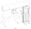
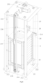
- a preferred embodiment of a high-speed smart cutting and processing center of the present invention includes a cutting machine 1, a die cutter magazine 2 and a die cutter circulation table 3.
- the cutting machine 1 includes a machine base, a working table 4 and a cross beam 5, where the working table 4 and the cross beam 5 are disposed on the machine base.
- the cross beam 5 is located above the working table 4.
- a punch slide rail 6 is disposed at the front and rear sides of the cross beam 5 respectively.
- a matching punch slide seat 7 is disposed on the two punch slide rails 6 respectively.
- a rotary cutting head 8 is disposed under the punch slide seats 7.
- a die cutter fixing plate 10 is disposed at the bottom of the rotary cutting head 8.
- a die cutter A for cutting and a die cutter clamping and limiting device 9 are disposed on the die cutter fixing plate 10. The clamping and limiting device 9 is used to achieve limiting and clamping on an imported die cutter A or achieve unlocking and release on a die cutter to be exported.
- the die cutter circulation table 3 is located at the left side of the working table 4. One end of the die cutter circulation table 3 is connected with the die cutter magazine 2 and the other end is connected with the working table 4.
- the rotary cutting head 8 may move to be above the die cutter circulation table 3.
- the die cutter circulation table 3 is used to pull out a die cutter A from the die cutter magazine 2 and mount it into the clamping and limiting device 9 of the rotary cutting head 8 or pull out and return the die cutter A in the clamping and limiting device 9 of the rotary cutting head 8 to the die cutter magazine 2.
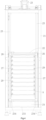
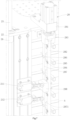
- the die cutter magazine 2 includes a frame 21, a die cutter storage rack 22 and a lifting device 23, where the die cutter storage rack 22 and the lifting device 23 are disposed within the frame 21.
- An exit-entry portion 24 for the die cutter A to enter and exit the die cutter storage rack 22 is disposed at the front and rear sides of the frame 21 respectively.
- the exit-entry portion 24 at the front side is connected with the cutting machine 1 to provide a desired die cutter A to the cutting machine 1.
- the exit-entry portion 24 at the rear side is used to change and sequentially configure the die cutters A in the frame 21.
- a plurality of die cutters A are stacked up and down in different layers in the die cutter storage rack 22.
- Guide columns 25 are disposed at four corners of the frame 21, and guide sleeves 26 slidably cooperating with the guide columns 25 are disposed on the die cutter storage rack 22.
- the lifting device 23 drives the die cutter storage rack 22 to move up and down along the guide columns 25.
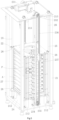
- the lifting device 23 includes a motor gear box 231 provided with a dual-output shaft, driving belt wheels 232, a driven shaft 233, driven bearings 234, driven belt wheels 235 and synchronous belts 236.
- the motor gear box 231 is disposed on the top of the frame 21.
- Two driving belt wheels 232 are respectively disposed on both ends of the output shaft.
- Two driven bearings 234 are fixed at a lower portion of the frame 21 and located below the die cutter storage rack 22.
- the driven shaft 233 is penetrated through the two driven bearings 234, and the driven belt wheels 235 are disposed on both ends of the driven shaft 233.
- the driving belt wheels 232 drive the driven belt wheels 235 to rotate by the synchronous belts 236.
- a synchronous belt 236 is disposed on left and right sides of the frame 21 respectively, and each synchronous belt 236 is provided with a cutter rack fixing plate 237.
- One end of the cutter rack fixing plate 237 is fixed on the synchronous belt 236, and the other end is fixed on the storage rack 22 at this side.
- the two synchronous belts 236 drive the die cutter storage rack 22 to move up and down along the guide columns 25 through respective cutter rack fixing plates 237 at the same time.
- a plurality of slideways 27 for placing the die cutters A are disposed at the left and right sides of the die cutter storage rack 22 respectively and a die cutter locking device 28 for positioning the die cutters A in the slideways 27 is disposed at the right side of the die cutter storage rack 22.
- the die cutter locking device 28 includes a locking cylinder 281, a locking operation rod 282, locking bearings 283, driving rods 284, locking rods 285, locking rod rotary shafts 286, and a rotary shaft fixing rod 287.
- the locking cylinder 281, the locking bearings 283, and the rotary shaft fixing rod 287 are respectively fixed to the die cutter storage rack 22.
- the locking cylinder 281 is fixed on an upper portion of the die cutter storage rack 22, and the locking operation rod 282 is fixedly connected with an output shaft of the locking cylinder 281.
- the locking operation rod 282 is penetrated through two locking bearings 283 which are fixed on the die cutter storage rack 22 and respectively located both ends of the locking operation rod 282.
- the locking operation rod 282 is slid up and down along the locking bearings 283 under the drive of the locking cylinder 281.
- the rotary shaft fixing rod 287 is fixed at a side of the die cutter storage rack 22, and the rotary shaft fixing rod 287 is provided with a plurality of avoiding holes 2871 each corresponding to a placement position of the each layer of die cutter A.
- the driving rods 284, the locking rods 285 and the locking rod rotary shafts 286 are disposed at a side of the placement position of each layer of die cutter A respectively by sets.
- the locking rod 285 is provided with a waist-shaped hole 2851, a rotary shaft hole 2852 and an arc-shaped portion 2853 respectively, where the waist-shaped hole 2851 and the arc-shaped portion 2853 are located at both sides of the rotary shaft hole 2852.
- the locking rod rotary shafts 286 are penetrated through the rotary shaft fixing rod 287 and the rotary shaft holes 2852 of the locking rods 285 to movably connect the locking rods 285 in the locking rod avoiding holes 2871 such that the locking rods 285 can rotate around the locking rod rotary shafts 286.
- One end of the driving rods 284 is fixed on the locking rods 85, and the other end is movable inserted into the waist-shaped holes 2851 of the locking rods 285.
- the arc-shaped portions 2853 of the locking rods 285 are fitted into limiting grooves B of side edges of the die cutters A, as shown in FIG. 8 .
- the locking operation rod 282 slides up and down and thus drives the locking rods 285 to rotate around the locking rod rotary shafts 286 through the driving rods 84, such that the arc-shaped portions 2853 of the locking rods 285 are fitted into the limiting grooves B of the die cutters A so as to lock up the die cutters A, or the arc-shaped portions 2853 of the locking rods 285 are released from the limiting grooves B of the die cutters A so as to unlock the die cutters A.
- the locking operation rod 282 is provided with a contact block 288, and an upper travel switch 210 and a lower travel switch 211 cooperating with the contact block 288 are respectively disposed on the frame 21.
- the contact block 288 moves up and down along with the locking operation rod 282 to trigger the upper travel switch 210 and the lower travel switch 211 respectively so as to limit the upper and lower positions for the movement of the locking operation rod 282, thereby improving the operation safety of the die cutter locking device 28.
- the response time of the die cutter locking device 28 can be shortened and the working efficiency of the die cutter supply system can be improved.
- a roller 29 is disposed at a sidewall of each slideway 27.
- the rollers 29 are located above the die cutters A and close to the exit-entry portion 24 at the back of the frame 21, so as to achieve limiting and guiding effect when the die cutters A are guided into or out of the die cutter storage rack 22.
- a cutter rack support column 212 is disposed at the bottom of the die cutter storage rack 22 and fixed on the frame 21.
- a cutter rack limiting column 213 is disposed on the top of the frame 21. In this embodiment, four cutter rack support columns 212 are disposed correspondingly at four corners of the bottom of the die cutter storage rack 22, and four cutter rack limiting columns 213 are disposed correspondingly at four corners of the top of the frame 21. In this way, the safety and stability of the die cutter storage rack 22 can be improved.
- a stop switch 214 triggered by the die cutter storage rack 22 is disposed on the frame 21.
- the stop switch 214 is used to limit a descending position of the die cutter storage rack 22, thereby improving the movement safety and stability of the die cutter storage rack 22.
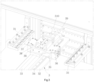
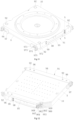
- the die cutter circulation table 3 includes two raceway plates 31, a cylinder mounting plate 32, a primary thrust cylinder 33, a thrust slide rail 34, a thrust block 35, two lifting cylinders 36, a cylinder connection plate 37, a secondary thrust cylinder 38, and a hook plate 39 with a pull hook 310.
- One end of the two raceway plates 31 is connected to the die cutter magazine 2, and the other end is connected with the working table 4.
- the two raceway plates 31 are separated left and right to form a channel for the die cutter A to enter or exit the die cutter magazine 2.
- the cylinder mounting plate 32 is fixed on the working table 4, and the primary thrust cylinder 33 and the thrust slide rail 34 are fixed on the cylinder mounting plate 32.
- the primary thrust cylinder 33 is a rodless cylinder which drives the thrust block 35 to reciprocate along the thrust slide rail 34.
- the primary thrust cylinder 33 and the secondary thrust cylinder 38 are disposed, which not only shortens the length of the primary thrust cylinder 33 but also avoids excess length of the primary thrust cylinder 33, thereby saving costs and improving the movement stability of the thrust block 35. Furthermore, when the two stages of cylinders thrust or retreat, they can thrust or retreat at the same time, shortening the thrust or retreat time and achieving fast movement of the thrust block 35. Further, the die cutters A can be stably and quickly changed, thereby improving working efficiency.
- the disposal of the thrust slide rail 34 increases the stability of the thrust block 35 in quick thrust or retreat process.
- the two lifting cylinders 36 are respectively fixed at the left and right sides of the thrust block 35.
- the cylinder connection plate 37 is linked to cylinder rods of the two lifting cylinders 36 respectively.
- the secondary thrust cylinder 38 is fixed on the cylinder connection plate 37, and the hook plate 39 is disposed on a cylinder rod of the secondary thrust cylinder 38.
- the primary thrust cylinder 33 drives, by the thrust block 35, the two lifting cylinders 36, the cylinder connection plate 37, the secondary thrust cylinder 38 and the hook plate 39 to reciprocate along the thrust slide rail 34 at the same time.
- the pull hook 310 on the hook plate 39 is inserted into a hook hole C on the die cutterAas shown in FIG. 8 , such that the die cutter A is pushed into the released clamping and limiting device 9 or pulled out from the released clamping and limiting device 9.
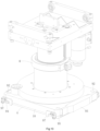
- the clamping and limiting device 9 includes a clamping assembly 91 and a limiting assembly and is mounted on the die cutter fixing plate 10 located at the bottom of the cutting machine 1.
- the clamping assembly 91 includes a left die pressing plate 94, a right die pressing plate 95, and pressing cylinders 96.
- the left die pressing plate 94 and the right die pressing plate 95 are disposed on the left and right side edges of a lower surface of the die cutter fixing plate 10 respectively.
- the pressing cylinders 96 are disposed inside the die cutter fixing plate 10 and located at four corners of the die cutter fixing plate 10 in a manner of left-right and back-front symmetry.
- the pressing cylinders 96 drive the left die pressing plate 94 and the right die pressing plate 95 respectively to press the die cutter A closely against the lower surface of the die cutter fixing plate 10.
- the limiting assembly includes front limiting components and rear limiting components located at front and rear side surfaces of the die cutter fixing plate 10. At least one of the front limiting component and the rear limiting component is a movable limiting component 97 and the other is a fixed limiting component or movable limiting component 97.
- the movable limiting components 97 perform limiting or unlocking for the front and rear side surfaces of the die cutter A in linkage with the left die pressing plate 94 or the right die pressing plate 95. As shown in FIGS. 10 , 11, and 12 , movable limiting components 97 are disposed at the front and rear side surfaces of the die cutter fixing plate 10.
- the left die pressing plate 94 and the right die pressing plate 95 press the die cutter A closely against the lower surface of the die cutter fixing plate 10 along an up-down direction under the drive of the pressing cylinders 6.
- the limiting assembly performs limiting for the front and rear side surfaces of the die cutter A. In this way, the position repeatability and positioning accuracy of the die cutter is improved and the size accuracy of the cut products is also improved.
- the limiting assembly acts in the following process: when the left die pressing plate 94 and the right die pressing plate 95 of the clamping assembly 91 press the die cutter A closely against the lower surface of the die cutter fixing plate 10, the movable limiting components 97 perform limiting for the front side surface and/or rear side surface of the die cutter A immediately. On the contrary, when the left die pressing plate 94 and the right die pressing plate 95 of the clamping assembly 91 release the up-down press on the die cutter A, the movable limiting components 97 release limitation for the front side surface and/or the rear side surface of the die cutter A immediately.
- Two pressing cylinders 96 are disposed at the right and left sides of the die cutter fixing plate 10 respectively.
- the two pressing cylinders 96 act simultaneously to press or release the die cutter A.
- the pressing cylinder 96 includes a cylindrical hole 961, a valve core shaft 962, an upper piston 963, a lower piston 964, an upper air chamber 965 and a lower air chamber 966, where the cylindrical hole 61 is disposed inside the die cutter fixing plate 10 and the valve core shaft 962, the upper piston 963, the lower piston 964, the upper air chamber 965 and the lower air chamber 966 are disposed inside the cylindrical hole 961.
- the upper piston 963 and the lower piston 964 are disposed on the valve core shaft 962 respectively.
- the upper air chamber 965 is disposed between the upper piston 963 and the top wall of the cylindrical hole 961.
- the lower air chamber 966 is disposed between the upper piston 963 and the lower piston 964.
- An upper air pipe connector 98 and a lower air pipe connector 99 are disposed on the die cutter fixing plate 10 respectively.
- the upper air pipe connector 98 and the lower air pipe connector 99 are in communication with the upper air chamber 965 and the lower air chamber 966 through an upper channel 967 and a lower channel 968 disposed in the die cutter fixing plate 10.
- the pressing cylinders 96 are directly made inside the die cutter fixing plate 10, which simplifies the structure of the die cutter clamping and limiting device, reduces the weight of the die cutter fixing plate 10 and improves its stability.
- the pressing cylinders 96 act in the following process: when high pressure air is introduced into the upper air chamber 965 via the upper air pipe connector 98, the lower air chamber 966 recovers air via the lower air pipe connector 99, and then the valve core shaft 962 is driven to move down together with the upper piston 963 and the lower piston 964 disposed thereon, and then the valve core shaft 962 pushes open the left die pressing plate 94 or the right die pressing plate 95, thereby unlocking the die cutter A.
- the upper air chamber 965 recovers air via the upper air pipe connector 98, and then the valve core shaft 962 is driven to move up for resetting together with the upper piston 963 and the lower piston 964 disposed thereon, and then the valve core shaft 962 drives the left die pressing plate 94 or the right die pressing plate 95 closely against the die cutter A.
- a stop washer 969 is disposed on an inner wall of the cylindrical hole 961 to limit a movement position of the lower piston 964, so as to limit a movement position of the valve core shaft 962, thereby limiting a telescoping height of the pressing cylinder 96.
- the fixed limiting component includes a limiting block and a fastening bolt (not shown).
- the limiting block limits the movement position of the die cutter A, and the fastening bolt fixes the limiting block on a side surface of the die cutter fixing plate 10.
- the movable limiting component 97 includes a first connection bar 971, a second connection bar 972, a first rotary shaft 973, a second rotary shaft 974, and a third rotary shaft 975.
- the first rotary shaft 973 is fixed on the die cutter fixing plate 10
- the third rotary shaft 975 is fixed on the left die pressing plate 94 or the right die pressing plate 95.
- the first rotary shaft 973 is movable disposed in the middle of the first connection bar 971, and the second rotary shaft 74 movably connects an end of the first connection bar 971 to an end of the second connection bar 972.
- a blocking portion 976 is disposed on the other end of the first connection bar 971 to limit the die cutter A, and the other end of the second connection bar 972 is movably connected with the third rotary shaft 975.
- one segment of inclined surface or arc-shaped surface 977 is disposed on the blocking portion 976 of the first connection bar 971, and thus it is convenient to push the die cutter A back to a correct limiting position when the first connection bar 971 performs limiting for the die cutter A.
- the movable limiting component 97 acts in the following process: when the pressing cylinders 96 drive the left die pressing plate 94 or the right die pressing plate 95 to move down, the third rotary shaft 975 and the second connection bar 972 move down accordingly, and the second connection bar 972 also drives, via the second rotary shaft 974, an end of the first connection bar 971 to move down.
- the first connection bar 971 rotates around the first rotary shaft 973, so as to lift up the other end of the first connection bar 971, thus releasing the limited die cutter A.
- the pressing cylinders 96 drive the left die pressing plate 94 or the right die pressing plate 95 to move up
- the third rotary shaft 975 and the second connection bar 972 move up accordingly
- the second connection bar 972 drives, via the second rotary shaft 974, an end of the first connection bar 971 to move up.
- the first connection bar 971 rotates around the first rotary shaft 973, so as to lower the other end of the first connection bar 971, thus limiting the die cutter A.
- Limiting screws 92 are disposed between the left die pressing plate 94/the right die pressing plate 95 and the die cutter fixing plate 10. The limiting screws 92 are used to adjust and limit a maximum distance between the left die pressing plate 94/the right die pressing plate 95 and the die cutter fixing plate 10 respectively.
- the die cutter A can be quickly limited and clamped, thus achieving quick change of the die cutter A. Further, good position repeatability and high positioning accuracy are ensured.
- the present invention further provides a method of changing a die cutter, which is used on the above high-speed smart cutting and processing center.
- the method includes the following steps.
- the rotary cutting head 8 is moved from a working region in the middle of the working table 4 to be over the die cutter circulation table 3; the movable limiting components 97 of the clamping and limiting device 9 is moved close to the die cutter magazine 2; the rotary cutting head 8 drives the die cutter A to descend to a position for changing the die cutter; the pressing cylinders 96 drive the left die pressing plate 94 and the right die pressing plate 95 to move down respectively to enable the movable limiting components 97 to be in an unlocked state through linkage; the clamping assembly 91 is in a released state, and the old die cutter A1 waits for being changed.
- the primary thrust cylinder 33 drives the secondary thrust cylinder 38 and the hook plate 39 to move from an initial position toward the rotary cutting head 8; at the same time, the secondary thrust cylinder 38 also drives the hook plate 39 toward the rotary cutting head 8 until the hook plate 39 is located below the old die cutter A1 to be changed; two lifting cylinders 36 drive the secondary thrust cylinder 38 and the hook plate 39 to move upward through the cylinder connection plate 37 at the same time until the pull hook 310 of the hook plate 39 is inserted upward into the hook hole C of the old die cutter A1.
- step 3 the secondary thrust cylinder 38 and the primary thrust cylinder 33 move toward the die cutter magazine 2 at the same time; the old die cutter A is pulled out of the clamping and limiting device 9 in a released state in step 1 and moved to a set position in the die cutter magazine 2; next, two lifting cylinders 36 drive the hook plate 39 to move down and then the secondary thrust cylinder 38 retreats to enable the hook plate 39 to leave the die cutter magazine 2.
- the lifting device 23 in the die cutter magazine 2 acts to move a new die cutter A2 to a proper position; the secondary thrust cylinder 38 moves again toward the die cutter magazine 2, and the two lifting cylinders 36 lift the hook plate 39 again until the pull hook 310 of the hook plate 39 is inserted upward into the hook hole C of the new die cutter A2.
- the primary thrust cylinder 33 drives the secondary thrust cylinder 38 and the hook plate 39 toward the rotary cutting head 8; at the same time, the secondary thrust cylinder 33 also drives the hook plate 39 toward the rotary cutting head 8 until the hook plate 39 moves the new die cutter A2 into the clamping and limiting device 9 in a released state; the new die cutter A2 is stopped by the fixed limiting component at the other side, and the clamping assembly 91 acts reversely to clamp the new die cutter A2; the pressing cylinders 96 drive the left die pressing plate 94 and the right die pressing plate 95 to move upward to enable the movable limiting components 97 to be in a limiting state through linkage; thus, the new die cutter A2 is clamped and limited; then, two lifting cylinders 36 drive the hook plate 39 to move down, and then the primary thrust cylinder 33 and the second thrust cylinder 38 retreat to their initial positions; the rotary cutting head 8 is lifted up and returned to the working region in the middle of the working table 4, thereby completing the cycle of changing the die cutter.
- the above process can be operated at high speed on the cutting machine of the present invention under the control of a smart operating system.
Landscapes
- Engineering & Computer Science (AREA)
- Mechanical Engineering (AREA)
- Life Sciences & Earth Sciences (AREA)
- Forests & Forestry (AREA)
- Perforating, Stamping-Out Or Severing By Means Other Than Cutting (AREA)
- Mounting, Exchange, And Manufacturing Of Dies (AREA)
Claims (9)
- Centre de découpe et d'usinage intelligent à haute vitesse, comprenant une machine à découper (1), un chargeur d'emporte-pièces (2) et une table de déplacement d'emporte-pièces (3), dans lequel la machine à découper (1) inclut une base de machine, une table de travail (4) et une barre transversale (5), où la table de travail (4) et la barre transversale (5) sont disposées sur la base de machine, des rails de coulissement à poinçons (6) sont disposés sur la barre transversale (5), des sièges de coulissement à poinçons (7) correspondants sont disposés sur les rails de coulissement à poinçons (6) respectivement, une tête de découpe rotative (8) est disposée sous les sièges de coulissement à poinçons (7), une plaque de fixation d'emporte-pièces (10) est disposée sur le bas de la tête de découpe rotative (8), un emporte-pièce (A) de découpe et un dispositif de limitation et de serrage d'emporte-pièces (9) sont disposés sur le bas de la tête de découpe rotative (8), la table de déplacement d'emporte-pièces (3) se trouve sur le côté gauche de la table de travail (4), une extrémité de la table de déplacement d'emporte-pièces (3) est reliée au chargeur d'emporte-pièces (2) et l'autre extrémité est reliée à la table de travail (4), le chargeur d'emporte-pièces (2) comprend un cadre (21), un support de stockage d'emporte-pièces (22) et un dispositif de levage (23), où le support de stockage d'emporte-pièces (22) et le dispositif de levage (23) sont disposés dans le cadre (21), une pluralité d'emporte-pièces (A) sont empilés de haut en bas dans différentes couches dans le support de stockage d'emporte-pièces (22), des colonnes de guidage (25) sont disposées aux quatre coins du cadre (21), des manchons de guidage (26) coopérant de façon coulissante avec les colonnes de guidage (25) sont disposés sur le support de stockage d'emporte-pièces (22), le dispositif de levage (23) entraîne le support de stockage d'emporte-pièces (22) en déplacement vers le haut et vers le bas le long des colonnes de guidage (25), le dispositif de levage (23) comprend une boîte de transmission de moteur (231) disposée en haut du cadre (21), caractérisé en ce que la boîte de transmission de moteur (231) est dotée d'un arbre à double sortie, de roues de courroie d'entraînement (232), d'un arbre entraîné (233), de paliers entraînés (234), de roues de courroie entraînées (235) et de courroies synchrones (236), dans lequel deux roues de courroie d'entraînement (232) sont disposées respectivement aux deux extrémités de l'arbre de sortie, deux paliers entraînés (234) sont fixés à une partie inférieure du cadre (21) et situés sous le support de stockage d'emporte-pièces (22), dans lequel l'arbre entraîné (233) pénètre à travers les deux paliers entraînés (234), les roues de courroie entraînées (235) sont disposées aux deux extrémités de l'arbre entraîné (233), les roues de courroie d'entraînement (232) entraînent les roues de courroie entraînées (235) en rotation par le biais des courroies synchrones (236), dans lequel une courroie synchrone (236) est disposée sur des côtés gauche et droit du cadre (21) respectivement, et chaque courroie synchrone (236) est dotée d'une plaque de fixation de support d'emporte-pièces (237), une extrémité de la plaque de fixation de support d'emporte-pièces (237) est fixée à la courroie synchrone (236), et l'autre extrémité est fixée au support de stockage d'emporte-pièces (22) sur ce côté, dans lequel une pluralité de voies de coulissement (27) destinées au placement des emporte-pièces (A) sont disposées de haut en bas sur les côtés gauche et droit du support de stockage d'emporte-pièces (22) respectivement, un dispositif de verrouillage d'emporte-pièces (28) pour le positionnement des emporte-pièces (A) dans les voies de coulissement (27) est disposé sur le côté droit du support de stockage d'emporte-pièces (22), le dispositif de verrouillage d'emporte-pièces (28) comprend un cylindre de verrouillage (281), une tige d'actionnement de verrouillage (282), des paliers de verrouillage (283), des tiges d'entraînement (284), des tiges de verrouillage (285), des arbres rotatifs de tige de verrouillage (286), et une tige de fixation d'arbre rotatif (287), le cylindre de verrouillage (281) est fixé à une partie supérieure du support de stockage d'emporte-pièces (22), la tige d'actionnement de verrouillage (282) est reliée fixement à un arbre de sortie du cylindre de verrouillage (281), la tige d'actionnement de verrouillage (282) pénètre à travers deux paliers de verrouillage (283), lesquels sont fixés au support de stockage d'emporte-pièces (22) et situés respectivement aux deux extrémités de la tige d'actionnement de verrouillage (282), la tige d'actionnement de verrouillage (282) coulisse de haut en bas le long des paliers de verrouillage (283) sous l'entraînement du cylindre de verrouillage (281), la tige de fixation d'arbre rotatif (287) est fixée sur un côté du support de stockage d'emporte-pièces (22), la tige de fixation d'arbre rotatif (287) est dotée d'une pluralité de trous d'évitement (2871) correspondant respectivement à une position de placement de chaque couche d'emporte-pièces, les tiges d'entraînement (284), les tiges de verrouillage (285) et les arbres rotatifs de tige de verrouillage (286) sont disposés sur un côté de la position de placement de chaque couche d'emporte-pièces respectivement par jeux, la tiges de verrouillage est dotée d'un trou cintré (2851), d'un trou d'arbre rotatif (2852) et d'une partie arquée (2853) respectivement, les arbres rotatifs de tige de verrouillage (286) pénètrent à travers la tige de fixation d'arbre rotatif (287) et les trous d'arbre rotatif (2852) des tiges de verrouillage (285) pour relier les tiges de verrouillage (285) de façon mobile dans les trous d'évitement de tige de verrouillage (2871), une extrémité des tiges d'entraînement (284) est fixée aux tiges de verrouillage (285), et l'autre extrémité est insérée de façon mobile dans les trous cintrés (2851) des tiges de verrouillage (285), les parties arquées (2853) des tiges de verrouillage (285) sont ajustées dans des rainures de limitation (B) de bords latéraux des emporte-pièces (A), la tige d'actionnement de verrouillage (282) coulisse vers le haut et le bas, de manière à entraîner les tiges de verrouillage (285) en rotation autour des arbres rotatifs de tige de verrouillage (286) à travers les tiges d'entraînement (284).
- Centre de découpe et d'usinage intelligent à haute vitesse selon la revendication 1, dans lequel la tige d'actionnement de verrouillage (282) est dotée d'un bloc de contact (288), un commutateur de déplacement supérieur (210) et un commutateur de déplacement inférieur (211) coopérant avec le bloc de contact (288) sont disposés respectivement sur le cadre (21), et un commutateur d'arrêt (214) déclenché par le support de stockage d'emporte-pièces (22) est disposé sur le cadre (21).
- Centre de découpe et d'usinage intelligent à haute vitesse selon la revendication 1, dans lequel la table de déplacement d'emporte-pièces (3) comprend deux plaques de chemin de roulement (31), une plaque de montage de cylindre (32), un cylindre de poussée primaire (33), un rail de coulissement de poussée (34), un bloc de poussée (35), deux cylindres de levage (36), une plaque de connexion de cylindre (37), un cylindre de poussée secondaire (38), et une plaque à crochet (39) avec un crochet de traction (310), une extrémité des deux plaques de chemin de roulement (31) est reliée au chargeur d'emporte-pièces (2), et l'autre extrémité est reliée à la table de travail (4), les deux plaques de chemin de roulement (31) sont séparées à gauche et à droite pour former un canal permettant aux emporte-pièces d'entrer dans le chargeur d'emporte-pièces (2) ou de sortir de celui-ci, la plaque de montage de cylindre (32) est fixée à la table de travail (4), le cylindre de poussée primaire (33) et le rail de coulissement de poussée (34) sont fixés à la plaque de montage de cylindre (32), les deux cylindres de levage (36) sont fixés respectivement sur les côtés gauche et droit du bloc de poussée (35), la plaque de connexion de cylindre (37) est reliée aux tiges de cylindre des deux cylindres de levage (36) respectivement, le cylindre de poussée secondaire (38) est fixé à la plaque de connexion de cylindre (37), la plaque à crochet (39) est disposée sur une tige de cylindre du cylindre de poussée secondaire (38), le cylindre de poussée primaire (33) entraîne, par le biais du bloc de poussée (35), les deux cylindres de levage (36), la plaque de connexion de cylindre (37), le cylindre de poussée secondaire (38) et la plaque à crochet (39) de manière à ce qu'ils effectuent un mouvement alternatif le long du rail de coulissement de poussée (34) simultanément.
- Centre de découpe et d'usinage intelligent à haute vitesse selon la revendication 3, dans lequel le dispositif de limitation et de serrage d'emporte-pièces (9) comprend un ensemble de serrage (91) et un ensemble de limitation et est monté sur la plaque de fixation d'emporte-pièces (10) de la machine à découper (1), l'ensemble de serrage (91) comprend une plaque de pression d'emporte-pièces de gauche (94), une plaque de pression d'emporte-pièces de droite (95) et des cylindres de pression (96), deux cylindres de pression (96) sont disposés sur les côtés gauche et droit de la plaque de fixation d'emporte-pièces (10) respectivement et agissent simultanément pour presser ou relâcher l'emporte-pièce (A), la plaque de pression d'emporte-pièces de gauche (94) et la plaque de pression d'emporte-pièces de droite (95) sont disposées sur les bords latéraux gauche et droit d'une surface inférieure de la plaque de fixation d'emporte-pièces (10) respectivement, les cylindres de pression (96) sont disposés à l'intérieur de la plaque de fixation d'emporte-pièces (10) et entraînent la plaque de pression d'emporte-pièces de gauche (94) et la plaque de pression d'emporte-pièces de droite (95) respectivement de manière à ce qu'elles pressent l'emporte-pièce (A) étroitement contre la surface inférieure de la plaque de fixation d'emporte-pièces (10), l'ensemble de limitation comprend des composants de limitation avant et des composants de limitation arrière situés sur des surfaces latérales avant et arrière de la plaque de fixation d'emporte-pièces (10), l'un au moins parmi le composant de limitation avant et le composant de limitation arrière est un composant de limitation mobile (97) et l'autre est un composant de limitation fixe ou un composant de limitation mobile (97), et les composants de limitation mobiles (97) assurent une limitation pour les surfaces latérales avant et arrière de l'emporte-pièce (A) en liaison avec la plaque de pression d'emporte-pièces de gauche (94) ou la plaque de pression d'emporte-pièces de droite (95).
- Centre de découpe et d'usinage intelligent à haute vitesse selon la revendication 4, dans lequel le cylindres de pression (96) comprend un trou cylindrique (961), un arbre de noyau de soupape, un piston supérieur (963), un piston inférieur (964), une chambre à air supérieure (965) et une chambre à air inférieure (966), où le trou cylindrique (961) est disposé à l'intérieur de la plaque de fixation d'emporte-pièces (10) et l'arbre de noyau de soupape, le piston supérieur (963), le piston inférieur (964), la chambre à air supérieure (965) et la chambre à air inférieure (966) sont disposés à l'intérieur du trou cylindrique (961) ; le piston supérieur (963) et le piston inférieur (964) sont disposés sur l'arbre de noyau de soupape (962) respectivement, la chambre à air supérieure (965) est disposée entre le piston supérieur (963) et la paroi supérieure du trou cylindrique (961), la chambre à air inférieure (966) est disposée entre le piston supérieur (963) et le piston inférieur (964), un raccord de tuyau d'air supérieur (98) et un raccord de tuyau d'air inférieur (99) sont disposés sur la plaque de fixation d'emporte-pièces (10) respectivement, le raccord de tuyau d'air supérieur (98) et le raccord de tuyau d'air inférieur (99) sont en communication avec la chambre à air supérieure (965) et la chambre à air inférieure (966) par le biais d'un canal supérieur (967) et d'un canal inférieur (968) disposés dans la plaque de fixation d'emporte-pièces (10), et une rondelle d'arrêt est disposée sur une paroi intérieure du trou cylindrique (961) pour limiter une position de déplacement du piston inférieur (964).
- Centre de découpe et d'usinage intelligent à haute vitesse selon la revendication 4, dans lequel le composant de limitation mobile (97) comprend une première barre de liaison (971), une deuxième barre de liaison (972), un premier arbre rotatif (973), un deuxième arbre rotatif (974) et un troisième arbre rotatif (975), le premier arbre rotatif (973) est fixé à la plaque de fixation d'emporte-pièces (10), le troisième arbre rotatif (975) est fixé à la plaque de pression d'emporte-pièces de gauche (94) ou à la plaque de pression d'emporte-pièces de droite (95), le premier arbre rotatif (973) est disposé de façon mobile au milieu de la première barre de liaison (971), le deuxième arbre rotatif (974) relie de façon mobile une extrémité de la première barre de liaison (971) à une extrémité de la deuxième barre de liaison (972), une partie de blocage (976) est disposée à l'autre extrémité de la première barre de liaison (971) pour limiter l'emporte-pièce (A), et l'autre extrémité de la deuxième barre de liaison (972) est reliée de façon mobile au troisième arbre rotatif (975).
- Centre de découpe et d'usinage intelligent à haute vitesse selon la revendication 4, dans lequel le composant de limitation fixe comprend un bloc de limitation et un boulon de fixation, le bloc de limitation limite la position de déplacement de l'emporte-pièce (A), et le boulon de fixation fixe le bloc de limitation à une surface latérale de la plaque de fixation d'emporte-pièces (10).
- Centre de découpe et d'usinage intelligent à haute vitesse selon la revendication 4, dans lequel des vis de limitation (92) sont disposées entre le plaque de pression d'emporte-pièces de gauche (94)/la plaque de pression d'emporte-pièces de droite (95) et la plaque de fixation d'emporte-pièces (10), et les vis de limitation sont utilisées pour limiter une distance maximale entre la plaque de pression d'emporte-pièces de gauche (94)/la plaque de pression d'emporte-pièces de droite (95) et la plaque de fixation d'emporte-pièces (10) respectivement.
- Procédé de remplacement d'un emporte-pièce (A), lequel est utilisé sur le centre de découpe et d'usinage intelligent à haute vitesse selon la revendication 4 et comprend les étapes suivantes :dans l'étape 1, la tête de découpe rotative (8) est déplacée à partir d'une région de travail au milieu de la table de travail (4) pour se retrouver au-dessus de la table de déplacement d'emporte-pièces (3) ; les composants de limitation mobiles (97) du dispositif de limitation et de serrage d'emporte-pièces (9) sont déplacés à proximité du chargeur d'emporte-pièces (2) ; la tête de découpe rotative (8) entraîne l'emporte-pièce (A) en descente vers une position permettant le remplacement de l'emporte-pièce (A) ; les cylindres de pression (96) entraînent la plaque de pression d'emporte-pièces de gauche (94) et la plaque de pression d'emporte-pièces de droite (95) en déplacement vers le bas respectivement pour permettre aux composants de limitation mobiles (97) de se trouver dans un état déverrouillé par liaison ; l'ensemble de serrage (91) est dans un état relâché, et l'ancien emporte-pièce (A1) attend d'être remplacé ;dans l'étape 2, le cylindre de poussée primaire (33) entraîne le cylindre de poussée secondaire (38) et la plaque à crochet (39) en déplacement à partir d'une position initiale vers la tête de découpe rotative (8) ; simultanément, le cylindre de poussée secondaire (38) entraîne également la plaque à crochet (39) vers la tête de découpe rotative (8) jusqu'à ce que la plaque à crochet (39) se trouve sous un ancien emporte-pièce (A1) à remplacer ; deux cylindres de levage (36) entraînent le cylindre de poussée secondaire (38) et la plaque à crochet (39) en déplacement vers le haut à travers la plaque de connexion de cylindre (37) simultanément jusqu'à l'insertion du crochet de traction (310) de la plaque à crochet (39) vers le haut dans le trou de crochet (C) de l'ancien emporte-pièce (A1) ;dans l'étape 3, le cylindre de poussée secondaire (38) et le cylindre de poussée primaire (33) se déplacent simultanément vers le chargeur d'emporte-pièces (2) ; l'ancien emporte-pièce (A1) est retiré du dispositif de limitation et de serrage d'emporte-pièces (9) dans un état relâché dans l'étape 1 et déplacé vers une position définie dans le chargeur d'emporte-pièces (2) ; ensuite, deux cylindres de levage (36) entraînent la plaque à crochet (39) en déplacement vers le bas et puis le cylindre de poussée secondaire (38) recule pour permettre à la plaque à crochet (39) de quitter le chargeur d'emporte-pièces (2) ;dans l'étape 4, le dispositif de levage (23) dans le chargeur d'emporte-pièces (2) agit pour déplacer un nouvel emporte-pièce (A2) vers une position propre ; le cylindre de poussée secondaire (38) se déplace à nouveau vers le chargeur d'emporte-pièces (2), et les deux cylindres de levage (36) relèvent à nouveau la plaque à crochet (39) jusqu'à l'insertion du crochet de traction (310) de la plaque à crochet (39) vers le haut dans le trou de crochet (C) du nouvel emporte-pièce (A2) ;dans l'étape 5, le cylindre de poussée primaire (33) entraîne le cylindre de poussée secondaire (38) et la plaque à crochet (39) vers la tête de découpe rotative (8) ; simultanément, le cylindre de poussée secondaire (38) entraîne également la plaque à crochet (39) vers la tête de découpe rotative (8) jusqu'à ce que la plaque à crochet (39) déplace le nouvel emporte-pièce (A2) dans le dispositif de limitation et de serrage d'emporte-pièces (9) dans un état relâché ; le nouvel emporte-pièce (A2) est arrêté par le composant de limitation fixe de l'autre côté, et l'ensemble de serrage (91) agit inversement pour serrer le nouvel emporte-pièce (A2) ; les cylindres de pression (96) entraînent la plaque de pression d'emporte-pièces de gauche (94) et la plaque de pression d'emporte-pièces de droite (95) en déplacement vers le haut pour permettre aux composants de limitation mobiles (97) de se trouver dans un état de limitation par liaison ; ainsi, le nouvel emporte-pièce (A2) est serré et limité ; ensuite, deux cylindres de levage (36) entraînent la plaque à crochet (39) en déplacement vers le bas, et puis le cylindre de poussée primaire (33) et le cylindre de poussée secondaire (38) reculent vers leurs positions initiales ; la tête de découpe rotative (8) est relevée et renvoyée vers la région de travail au milieu de la table de travail (4), achevant ainsi le cycle de remplacement de l'emporte-pièce (A).
Applications Claiming Priority (2)
| Application Number | Priority Date | Filing Date | Title |
|---|---|---|---|
| CN202110566589.1A CN113134863B (zh) | 2021-05-24 | 2021-05-24 | 高速智能裁断加工中心以及更换刀模板的方法 |
| PCT/CN2021/138071 WO2022247237A1 (fr) | 2021-05-24 | 2021-12-14 | Centre d'usinage par coupe intelligent à grande vitesse et procédé de remplacement de plateaux matrices à lame |
Publications (4)
| Publication Number | Publication Date |
|---|---|
| EP4201614A1 EP4201614A1 (fr) | 2023-06-28 |
| EP4201614A4 EP4201614A4 (fr) | 2024-02-28 |
| EP4201614C0 EP4201614C0 (fr) | 2025-01-08 |
| EP4201614B1 true EP4201614B1 (fr) | 2025-01-08 |
Family
ID=76818064
Family Applications (1)
| Application Number | Title | Priority Date | Filing Date |
|---|---|---|---|
| EP21942800.0A Active EP4201614B1 (fr) | 2021-05-24 | 2021-12-14 | Centre d'usinage par coupe intelligent à grande vitesse et procédé de remplacement de plateaux matrices à lame |
Country Status (3)
| Country | Link |
|---|---|
| EP (1) | EP4201614B1 (fr) |
| CN (1) | CN113134863B (fr) |
| WO (1) | WO2022247237A1 (fr) |
Families Citing this family (12)
| Publication number | Priority date | Publication date | Assignee | Title |
|---|---|---|---|---|
| CN113134863B (zh) * | 2021-05-24 | 2024-02-27 | 衢州台威精工机械有限公司 | 高速智能裁断加工中心以及更换刀模板的方法 |
| CN113146724B (zh) * | 2021-05-24 | 2025-09-19 | 衢州台威精工机械有限公司 | 刀模供给系统及使用该系统的高速智能裁断加工中心 |
| CN113172694A (zh) * | 2021-05-24 | 2021-07-27 | 衢州台威精工机械有限公司 | 一种高速智能数控液压裁断机 |
| CN115157841B (zh) * | 2022-06-28 | 2023-11-03 | 温州强大新材料科技有限公司 | 镭射膜无缝压模设备及制备工艺 |
| CN118386666A (zh) * | 2023-03-16 | 2024-07-26 | 刘晓波 | 一种用于锂电池铝塑膜移印和模切的一体化装置 |
| CN116352811B (zh) * | 2023-04-18 | 2025-10-14 | 余姚市宝马印刷器材有限公司 | 一种方便拆卸更换的模切刀 |
| CN116766324A (zh) * | 2023-06-30 | 2023-09-19 | 苏州利乐电子科技有限公司 | 一种小尺寸背胶模切系统及其方法 |
| CN117021220B (zh) * | 2023-08-23 | 2025-09-12 | 苏州市职业大学(苏州开放大学) | 一种板材冲孔装置 |
| CN117374007B (zh) * | 2023-12-04 | 2024-03-15 | 容泰半导体(江苏)有限公司 | 一种具有刀具切换功能的半导体切筋成型装置 |
| CN117644396B (zh) * | 2023-12-13 | 2025-01-14 | 江苏天力建机电科技发展有限公司 | 一种铁路道岔平垫板钻孔装置及方法 |
| CN118782502B (zh) * | 2024-07-31 | 2024-12-24 | 通威微电子有限公司 | 碳化硅晶圆贴膜装置 |
| CN119795076B (zh) * | 2025-01-13 | 2025-07-11 | 滁州爱沃富光电科技有限公司 | 一种用于光子芯片检测的快速定位机构 |
Family Cites Families (17)
| Publication number | Priority date | Publication date | Assignee | Title |
|---|---|---|---|---|
| CN1171993A (zh) * | 1997-03-31 | 1998-02-04 | 杨维雄 | 摇臂式下料机 |
| JP3185019B2 (ja) * | 1997-11-14 | 2001-07-09 | 株式会社ワコール | プレス裁断機および裁断用刃型 |
| US6209436B1 (en) * | 1998-03-02 | 2001-04-03 | Container Graphics Corporation | Cutting die for cutting corrugated board having a quick attach/detach blade securing mechanism |
| JP3515952B2 (ja) * | 2000-11-22 | 2004-04-05 | 株式会社協和製作所 | スリッタの刃物交換装置及び刃物交換方法 |
| KR100809912B1 (ko) * | 2006-07-27 | 2008-03-04 | 한재형 | 3차원 프레스 로봇시스템 및 3차원 프레스 로봇시스템을이용한 프레스 소재 운반방법 |
| CN105216058B (zh) * | 2015-10-13 | 2017-03-01 | 盐城市华森机械有限公司 | 液压龙门裁断机自动刀模库 |
| CN106734503B (zh) * | 2016-11-25 | 2018-07-10 | 盐城市华森机械有限公司 | 自动换刀模式异形材料冲裁机 |
| CN207077527U (zh) * | 2017-04-10 | 2018-03-09 | 盐城市华森机械有限公司 | 一种片材切割高效裁切机 |
| CN107097294A (zh) * | 2017-06-19 | 2017-08-29 | 盐城市华森机械有限公司 | 一种片材切割高效裁切机 |
| CN107718160B (zh) * | 2017-09-27 | 2019-06-07 | 北京快鹿织造有限公司 | 一种液压龙门裁断机 |
| CN108384904A (zh) * | 2018-05-30 | 2018-08-10 | 盐城市裕正精密机械有限公司 | 全自动皮革裁断机 |
| CN108582254A (zh) * | 2018-05-30 | 2018-09-28 | 盐城市裕正精密机械有限公司 | 裁断机刀模架升降传动机构 |
| CN209793905U (zh) * | 2019-01-28 | 2019-12-17 | 温州永裕智能科技有限公司 | 一种自动换刀式裁断机 |
| CN212525693U (zh) * | 2019-12-06 | 2021-02-12 | 盐城市裕正精密机械有限公司 | 裁断机刀模库结构 |
| CN112297115A (zh) * | 2020-11-05 | 2021-02-02 | 东莞市陆陆兴工业自动化科技有限公司 | 一种自动换刀裁断机 |
| CN113134863B (zh) * | 2021-05-24 | 2024-02-27 | 衢州台威精工机械有限公司 | 高速智能裁断加工中心以及更换刀模板的方法 |
| CN215511311U (zh) * | 2021-05-24 | 2022-01-14 | 衢州台威精工机械有限公司 | 一种高速智能裁断加工中心 |
-
2021
- 2021-05-24 CN CN202110566589.1A patent/CN113134863B/zh active Active
- 2021-12-14 EP EP21942800.0A patent/EP4201614B1/fr active Active
- 2021-12-14 WO PCT/CN2021/138071 patent/WO2022247237A1/fr not_active Ceased
Also Published As
| Publication number | Publication date |
|---|---|
| EP4201614C0 (fr) | 2025-01-08 |
| CN113134863B (zh) | 2024-02-27 |
| EP4201614A4 (fr) | 2024-02-28 |
| CN113134863A (zh) | 2021-07-20 |
| EP4201614A1 (fr) | 2023-06-28 |
| WO2022247237A1 (fr) | 2022-12-01 |
Similar Documents
| Publication | Publication Date | Title |
|---|---|---|
| EP4201614B1 (fr) | Centre d'usinage par coupe intelligent à grande vitesse et procédé de remplacement de plateaux matrices à lame | |
| CA1238775A (fr) | Machine de multitraitement | |
| KR101621064B1 (ko) | 프로파일의 펀칭 및 노칭 자동가공장치 | |
| CN205112021U (zh) | 一种长板料钻孔机 | |
| US4503741A (en) | Bridge type punch press | |
| US6478571B1 (en) | Clamping apparatus of an injection molding machine | |
| CN106926316A (zh) | 一种片材切割高效裁切机 | |
| CN215511311U (zh) | 一种高速智能裁断加工中心 | |
| US6648568B2 (en) | Linear blind broaching machine | |
| EP4201616B1 (fr) | Système d'alimentation pour outils de poinçonnage | |
| CN117086393A (zh) | 一种立式龙门加工中心自动剪切设备 | |
| EP0100282B1 (fr) | Poinçonneuse à portique | |
| JP3051841B1 (ja) | 加圧装置 | |
| CN214686868U (zh) | 刀模供给系统及使用该系统的高速智能裁断加工中心 | |
| KR100212592B1 (ko) | 프레스 가공기 | |
| CN217727200U (zh) | 成孔装置及其机组 | |
| CN210733395U (zh) | 一种液压机的无源起降式高速移动工作台 | |
| CN213202254U (zh) | 一种随行工装升降旋转装置 | |
| CN115041745B (zh) | 一种基于皮带连续送料结构的十刀库裁断机 | |
| CN223093615U (zh) | 一种驱动机构及定子嵌线装置 | |
| CN222712242U (zh) | 一种座椅锁下盖冲压加工设备 | |
| CN222710666U (zh) | 一种具有自动送料功能的闭式双点连续冲床 | |
| CN219851906U (zh) | 一种立式辗环机轴向调节机构 | |
| CN221434642U (zh) | 一种齿轮箱盖加工用冲压成型模具 | |
| CN223440877U (zh) | 电池端板加工冲床 |
Legal Events
| Date | Code | Title | Description |
|---|---|---|---|
| STAA | Information on the status of an ep patent application or granted ep patent |
Free format text: STATUS: THE INTERNATIONAL PUBLICATION HAS BEEN MADE |
|
| PUAI | Public reference made under article 153(3) epc to a published international application that has entered the european phase |
Free format text: ORIGINAL CODE: 0009012 |
|
| STAA | Information on the status of an ep patent application or granted ep patent |
Free format text: STATUS: REQUEST FOR EXAMINATION WAS MADE |
|
| 17P | Request for examination filed |
Effective date: 20230321 |
|
| AK | Designated contracting states |
Kind code of ref document: A1 Designated state(s): AL AT BE BG CH CY CZ DE DK EE ES FI FR GB GR HR HU IE IS IT LI LT LU LV MC MK MT NL NO PL PT RO RS SE SI SK SM TR |
|
| A4 | Supplementary search report drawn up and despatched |
Effective date: 20240126 |
|
| RIC1 | Information provided on ipc code assigned before grant |
Ipc: B26D 5/00 20060101ALI20240122BHEP Ipc: B26F 1/40 20060101ALI20240122BHEP Ipc: B26D 7/26 20060101ALI20240122BHEP Ipc: B26F 1/38 20060101ALI20240122BHEP Ipc: B26D 7/08 20060101AFI20240122BHEP |
|
| DAV | Request for validation of the european patent (deleted) | ||
| DAX | Request for extension of the european patent (deleted) | ||
| GRAP | Despatch of communication of intention to grant a patent |
Free format text: ORIGINAL CODE: EPIDOSNIGR1 |
|
| STAA | Information on the status of an ep patent application or granted ep patent |
Free format text: STATUS: GRANT OF PATENT IS INTENDED |
|
| INTG | Intention to grant announced |
Effective date: 20241018 |
|
| GRAS | Grant fee paid |
Free format text: ORIGINAL CODE: EPIDOSNIGR3 |
|
| GRAA | (expected) grant |
Free format text: ORIGINAL CODE: 0009210 |
|
| STAA | Information on the status of an ep patent application or granted ep patent |
Free format text: STATUS: THE PATENT HAS BEEN GRANTED |
|
| AK | Designated contracting states |
Kind code of ref document: B1 Designated state(s): AL AT BE BG CH CY CZ DE DK EE ES FI FR GB GR HR HU IE IS IT LI LT LU LV MC MK MT NL NO PL PT RO RS SE SI SK SM TR |
|
| REG | Reference to a national code |
Ref country code: GB Ref legal event code: FG4D |
|
| REG | Reference to a national code |
Ref country code: CH Ref legal event code: EP |
|
| REG | Reference to a national code |
Ref country code: DE Ref legal event code: R096 Ref document number: 602021024849 Country of ref document: DE |
|
| REG | Reference to a national code |
Ref country code: IE Ref legal event code: FG4D |
|
| U01 | Request for unitary effect filed |
Effective date: 20250121 |
|
| U07 | Unitary effect registered |
Designated state(s): AT BE BG DE DK EE FI FR IT LT LU LV MT NL PT RO SE SI Effective date: 20250127 |
|
| PG25 | Lapsed in a contracting state [announced via postgrant information from national office to epo] |
Ref country code: RS Free format text: LAPSE BECAUSE OF FAILURE TO SUBMIT A TRANSLATION OF THE DESCRIPTION OR TO PAY THE FEE WITHIN THE PRESCRIBED TIME-LIMIT Effective date: 20250408 |
|
| PG25 | Lapsed in a contracting state [announced via postgrant information from national office to epo] |
Ref country code: PL Free format text: LAPSE BECAUSE OF FAILURE TO SUBMIT A TRANSLATION OF THE DESCRIPTION OR TO PAY THE FEE WITHIN THE PRESCRIBED TIME-LIMIT Effective date: 20250108 |
|
| PG25 | Lapsed in a contracting state [announced via postgrant information from national office to epo] |
Ref country code: ES Free format text: LAPSE BECAUSE OF FAILURE TO SUBMIT A TRANSLATION OF THE DESCRIPTION OR TO PAY THE FEE WITHIN THE PRESCRIBED TIME-LIMIT Effective date: 20250108 |
|
| PG25 | Lapsed in a contracting state [announced via postgrant information from national office to epo] |
Ref country code: NO Free format text: LAPSE BECAUSE OF FAILURE TO SUBMIT A TRANSLATION OF THE DESCRIPTION OR TO PAY THE FEE WITHIN THE PRESCRIBED TIME-LIMIT Effective date: 20250408 Ref country code: IS Free format text: LAPSE BECAUSE OF FAILURE TO SUBMIT A TRANSLATION OF THE DESCRIPTION OR TO PAY THE FEE WITHIN THE PRESCRIBED TIME-LIMIT Effective date: 20250508 |
|
| PG25 | Lapsed in a contracting state [announced via postgrant information from national office to epo] |
Ref country code: HR Free format text: LAPSE BECAUSE OF FAILURE TO SUBMIT A TRANSLATION OF THE DESCRIPTION OR TO PAY THE FEE WITHIN THE PRESCRIBED TIME-LIMIT Effective date: 20250108 |
|
| PG25 | Lapsed in a contracting state [announced via postgrant information from national office to epo] |
Ref country code: GR Free format text: LAPSE BECAUSE OF FAILURE TO SUBMIT A TRANSLATION OF THE DESCRIPTION OR TO PAY THE FEE WITHIN THE PRESCRIBED TIME-LIMIT Effective date: 20250409 |
|
| PG25 | Lapsed in a contracting state [announced via postgrant information from national office to epo] |
Ref country code: SM Free format text: LAPSE BECAUSE OF FAILURE TO SUBMIT A TRANSLATION OF THE DESCRIPTION OR TO PAY THE FEE WITHIN THE PRESCRIBED TIME-LIMIT Effective date: 20250108 |
|
| PG25 | Lapsed in a contracting state [announced via postgrant information from national office to epo] |
Ref country code: CZ Free format text: LAPSE BECAUSE OF FAILURE TO SUBMIT A TRANSLATION OF THE DESCRIPTION OR TO PAY THE FEE WITHIN THE PRESCRIBED TIME-LIMIT Effective date: 20250108 |
|
| PG25 | Lapsed in a contracting state [announced via postgrant information from national office to epo] |
Ref country code: SK Free format text: LAPSE BECAUSE OF FAILURE TO SUBMIT A TRANSLATION OF THE DESCRIPTION OR TO PAY THE FEE WITHIN THE PRESCRIBED TIME-LIMIT Effective date: 20250108 |
|
| PLBE | No opposition filed within time limit |
Free format text: ORIGINAL CODE: 0009261 |
|
| STAA | Information on the status of an ep patent application or granted ep patent |
Free format text: STATUS: NO OPPOSITION FILED WITHIN TIME LIMIT |