EP4201499A1 - Verfahren und system zur selbstregulierung eines suppressors - Google Patents
Verfahren und system zur selbstregulierung eines suppressors Download PDFInfo
- Publication number
- EP4201499A1 EP4201499A1 EP22213415.7A EP22213415A EP4201499A1 EP 4201499 A1 EP4201499 A1 EP 4201499A1 EP 22213415 A EP22213415 A EP 22213415A EP 4201499 A1 EP4201499 A1 EP 4201499A1
- Authority
- EP
- European Patent Office
- Prior art keywords
- suppressor
- voltage
- state
- offset voltage
- slope
- Prior art date
- Legal status (The legal status is an assumption and is not a legal conclusion. Google has not performed a legal analysis and makes no representation as to the accuracy of the status listed.)
- Granted
Links
Images


Classifications
-
- G—PHYSICS
- G01—MEASURING; TESTING
- G01N—INVESTIGATING OR ANALYSING MATERIALS BY DETERMINING THEIR CHEMICAL OR PHYSICAL PROPERTIES
- G01N30/00—Investigating or analysing materials by separation into components using adsorption, absorption or similar phenomena or using ion-exchange, e.g. chromatography or field flow fractionation
- G01N30/02—Column chromatography
- G01N30/86—Signal analysis
- G01N30/8658—Optimising operation parameters
-
- G—PHYSICS
- G01—MEASURING; TESTING
- G01N—INVESTIGATING OR ANALYSING MATERIALS BY DETERMINING THEIR CHEMICAL OR PHYSICAL PROPERTIES
- G01N30/00—Investigating or analysing materials by separation into components using adsorption, absorption or similar phenomena or using ion-exchange, e.g. chromatography or field flow fractionation
- G01N30/96—Investigating or analysing materials by separation into components using adsorption, absorption or similar phenomena or using ion-exchange, e.g. chromatography or field flow fractionation using ion-exchange
-
- B—PERFORMING OPERATIONS; TRANSPORTING
- B01—PHYSICAL OR CHEMICAL PROCESSES OR APPARATUS IN GENERAL
- B01D—SEPARATION
- B01D15/00—Separating processes involving the treatment of liquids with solid sorbents; Apparatus therefor
- B01D15/08—Selective adsorption, e.g. chromatography
- B01D15/26—Selective adsorption, e.g. chromatography characterised by the separation mechanism
- B01D15/36—Selective adsorption, e.g. chromatography characterised by the separation mechanism involving ionic interaction, e.g. ion-exchange, ion-pair, ion-suppression or ion-exclusion
-
- G—PHYSICS
- G01—MEASURING; TESTING
- G01N—INVESTIGATING OR ANALYSING MATERIALS BY DETERMINING THEIR CHEMICAL OR PHYSICAL PROPERTIES
- G01N30/00—Investigating or analysing materials by separation into components using adsorption, absorption or similar phenomena or using ion-exchange, e.g. chromatography or field flow fractionation
- G01N30/02—Column chromatography
- G01N2030/022—Column chromatography characterised by the kind of separation mechanism
- G01N2030/027—Liquid chromatography
-
- G—PHYSICS
- G01—MEASURING; TESTING
- G01N—INVESTIGATING OR ANALYSING MATERIALS BY DETERMINING THEIR CHEMICAL OR PHYSICAL PROPERTIES
- G01N30/00—Investigating or analysing materials by separation into components using adsorption, absorption or similar phenomena or using ion-exchange, e.g. chromatography or field flow fractionation
- G01N30/96—Investigating or analysing materials by separation into components using adsorption, absorption or similar phenomena or using ion-exchange, e.g. chromatography or field flow fractionation using ion-exchange
- G01N2030/965—Investigating or analysing materials by separation into components using adsorption, absorption or similar phenomena or using ion-exchange, e.g. chromatography or field flow fractionation using ion-exchange suppressor columns
-
- G—PHYSICS
- G01—MEASURING; TESTING
- G01N—INVESTIGATING OR ANALYSING MATERIALS BY DETERMINING THEIR CHEMICAL OR PHYSICAL PROPERTIES
- G01N30/00—Investigating or analysing materials by separation into components using adsorption, absorption or similar phenomena or using ion-exchange, e.g. chromatography or field flow fractionation
- G01N30/02—Column chromatography
- G01N30/62—Detectors specially adapted therefor
- G01N30/64—Electrical detectors
Definitions
- This application relates, in general, to separating ionic species in ion chromatography, and more particularly to methods and systems for self-regulating a suppressor during ion chromatography.
- Ion chromatography is widely used in the analysis of samples containing anions or cations. And suppressors play an instrumental role in ion chromatography by allowing analytes to be detectable.
- a typical ion chromatography process begins with introducing a sample into a solution of conductive eluent, then chromatographically separating sample ions in the eluent, suppressing the eluent to remove eluent ions counter to sample ions, and detecting the sample ions.
- the purpose of suppression is to reduce the background conductivity of the eluent and increase the conductivity of the sample analytes, thus promoting subsequent conductive detection of the sample analytes.
- Suppressors are utilized to suppress eluent.
- Suppressors generally include an eluent channel and a regenerant channel, which are separated by an ion-exchange membrane.
- the membrane allows ions to pass between the channels while blocking liquid flow between channels.
- An electric potential is be applied to the suppressor that causes ions of a particular charge to pass through the membrane from eluent flowing through the eluent channel to regenerant flowing through the regenerant channel.
- a user must determine the voltage and/or current settings of a suppressor based upon various parameters.
- Such parameters include the electrolytic properties of a given eluent as well as the concentration of the eluent flowing through the suppressor and its flow rate.
- suppressors generally require currents higher than theoretically predicted for achieving quantitative suppression, especially when gradients of varying concentration are utilized.
- current systems provide users with a range of currents to be applied to the suppressor, and the users are often encouraged to increase the current if a lower range does not sufficiently suppress the eluent.
- higher currents generally translate into heat generation and higher background noise, especially under high eluent concentration conditions.
- One aspect of the present invention is directed to a method for self-regulating a suppressor of an ion chromatography system.
- the method may include: setting a power supply to provide an offset voltage V OS to the suppressor; activating the power supply to provide an applied voltage waveform V A to the suppressor in addition to the offset voltage V OS ; commencing an ion chromatography run on the ion chromatography system in which an eluent flows through the suppressor; measuring a current of the suppressor responsive to the offset and applied voltages V OS and V A during the ion chromatography run; determining a suppressor state of the suppressor based upon the measured current in response to the offset voltage; and/or adjusting the offset voltage V OS based upon the suppressor state, wherein (a) offset voltage V OS is increased for an unsuppressed state, and (b) offset voltage V OS is maintained for a suppressed state.
- the system may include: an ion chromatography suppressor including a liquid-sample channel, an ion-receiving channel, and an ion-exchange membrane configured to substantially block bulk liquid flow between the liquid-sample and ion-receiving channels while allowing passage of ions of one charge, positive or negative, between the channels; first and second electrodes in electrical communication with the liquid-sample and ion-receiving channels, respectively; a power supply for applying an electric potential to the suppressor via the first and second electrodes; and/or a control unit including one or more processors and memory.
- the one or more processors run software configured to perform the following steps: setting the power supply to provide an offset voltage V OS to the suppressor; activating the power supply to provide an applied voltage V A to the suppressor in addition to the offset voltage V OS ; commencing an ion chromatography run in which an eluent flows through the suppressor; measuring a current of the suppressor responsive to the offset and applied voltages V OS and V A during the ion chromatography run; determining a suppressor state of the suppressor based upon the measured current in response to the offset voltage; and/or adjusting the offset voltage V OS based upon the suppressor state, wherein (a) offset voltage V OS is increased for an unsuppressed state, and (b) offset voltage Vas is maintained for a suppressed state.
- a further aspect of the present invention is directed to a device for self-regulating the separation of ionic species in a liquid sample.
- the device may include: a power supply configured to apply an electric potential to an ion chromatography suppressor, the suppressor including a liquid-sample channel, an ion-receiving channel, and an ion-exchange membrane configured to substantially block bulk liquid flow between the liquid-sample and ion-receiving channels while allowing passage of ions of one charge, positive or negative, between the channels; and/or a control unit including one or more processors and memory.
- the one or more processors run software configured to perform the following steps: setting the power supply to provide an offset voltage V OS to the suppressor; activating the power supply to provide an applied voltage waveform V A to the suppressor in addition to the offset voltage V OS ; commencing an ion chromatography run in which an eluent flows through the suppressor; measuring a current of the suppressor responsive to the offset and applied voltages Vas and V A during the ion chromatography run; determining a suppressor state of the suppressor based upon the measured current in response to the offset voltage; and/or adjusting the offset voltage V OS based upon the suppressor state, wherein (a) offset voltage V OS is increased for an unsuppressed state, and (b) offset voltage V OS is maintained for a suppressed state.
- Embodiments of the invention may include one or more of the following features.
- a concentration of the eluent may be varied with time as the eluent flows through the suppressor, and wherein the adjusting step may vary the offset voltage V OS over time in response to the varied concentration of the eluent with time.
- Diminishing upper current may indicate electrical capacitance and resistance within the suppressor, and substantially constant current may indicate substantially constant electrical resistance within the suppressor.
- the determining step may be also based upon the measured current in response to the offset voltage, wherein increasing upper current indicates an over-suppressed state.
- the adjusting step may be also based on the suppressor state wherein offset voltage V OS is decreased for an over-suppressed state.
- the oscillating voltage may have a voltage amplitude A and a voltage frequency F, and the applied voltage V A may be a square-waveform voltage having a positive pulse width and a negative pulse width.
- a current slope (S P ) of the positive pulse width less than a first predetermined threshold may indicate an unsuppressed state.
- a substantially neutral current slope (S P ) of the positive pulse width greater than the first predetermined threshold and less than a second predetermined threshold may indicate a suppressed state.
- a current slope (S P ) of the positive pulse width greater than the second predetermined threshold may indicate an over-suppressed state.
- the applied voltage V A may be a square waveform voltage having a positive pulse width and a negative pulse width, wherein the positive pulse width has a slope S P .
- a slope S P of less than 0.1 mA/s may indicate an unsuppressed state
- a slope S P of 0.1 mA/s to 0.3 mA/s may indicate a suppressed state
- a slope S P greater than 0.3 mA/s may indicate an over-suppressed state.
- the applied voltage V A may be a square waveform voltage having a positive pulse width and a negative pulse width, wherein the negative pulse width has a slope S N .
- a slope S N greater than -0.05 mA/s may indicate an unsuppressed state, and a slope S N less than -0.05 may indicate a suppressed or over-suppressed state.
- the applied voltage V A may be an oscillating voltage having period T, wherein the measuring, determining, and adjusting steps are performed for each period T.
- the adjusting step may adjust the offset voltage Vas by an adjusted voltage ⁇ V each period T.
- the adjusted voltage ⁇ V may be less than the applied voltage V A .
- the adjusted voltage ⁇ V may be less than 10% of the applied voltage V A .
- the adjusted voltage ⁇ V may be 5 mV.
- Increasing upper current may indicate increased electrical resistance and thermal effects within the suppressor. And (a) a diminishing upper current may indicate an unsuppressed state of the eluent flowing through the suppressor, and (b) a substantially constant upper current may indicate a suppressed state
- the system may further include a chromatography column upstream from the suppressor and a conductivity detector downstream from the suppressor.
- the power supply may be a dedicated power supply providing the electric potential to the suppressor.
- the system may further include a power-supply module that includes the power supply and the control unit.
- the power supply may be a dedicated power supply providing the electric potential only to the suppressor.
- Chromatography is a separation technique where analytes within a sample mixture are separated while going through a chromatography column based on the analytes' distinct affinity for a stationary phase versus a mobile phase.
- IC ion chromatography
- analytes may be detected by conductivity detectors due to the electrical properties of ions.
- This inherently presents a challenge as the separated analytes are enveloped by a sea of eluent, which eluent is also conductive, whereby conductive detection of the eluting analyte can be impossible.
- This challenge may be resolved by utilizing a suppressor between the separation column and the conductivity detector that removes background conductivity of the eluent by turning the eluent into water, which effectively enhances the signal of the analyte.
- the mechanisms are slightly different for anion and cation analyses.
- sodium or potassium ions are respectively removed from the eluent flowing through the suppressor of sodium hydroxide or potassium hydroxide and the remaining hydroxide ions combine with hydronium ions to form water, which has a very low conductivity and thus lowers the background signal of the eluent.
- the counter cations of the analytes are replaced with hydronium, thus changing the analytes from a salt form to an acid form therefore enhancing their signals.
- metasulfunate and sulfunate are respectively removed from the eluent flowing through the suppressor of metasulfonic acid and sulfuric acid and the remaining hydronium ions combine with hydroxide ions to form water, which again lowers the background signal of the eluent.
- the counter anions of the analytes are replaced with hydroxide, thus transforming the analytes from a salt form to their base form therefore enhancing their signals.
- suppressors have evolved from single column devices that needed several regeneration cycles (such as those described in U.S. Patent Nos. 3,897,213 , 3,920,397 , 3,925,019 , 3,926,559 , and 5,597,734 ), to continuously regenerated in-line devices (such as those described in U.S. Patent No. 4,474,664 ), to more recent electrolytically regenerating devices (such as those shown in U.S. Patent Nos. 4,459,357 , 4,403,039 , 4,999,098 and 5,248,426 ), the entire content of which patents is incorporated herein for all purposes by this reference.
- a voltage is applied to a suppressor to effect an ion exchange between eluent and regenerant channels.
- the amount of voltage needed to sufficiently suppress the eluent is generally dependent on the eluent flow rate and concentration.
- the methods and systems herein allow for self-regulation of suppressors by determining the state of the suppressor to distinguish whether there is insufficient current, optimal current, or too much current being provided to the suppressor.
- the state of the suppressor may be determined based upon the impedance of the suppressor, in which capacitance may indicate an unsuppressed state, resistance may indicate a suppressed state, and resistance with thermal effects may indicate an over-suppressed state.
- FIG. 1 illustrates an exemplary chromatography (IC) system 30 in accordance with various aspects of the present invention.
- the IC system generally includes an eluent source 32, a sample injection valve 33, an ion-chromatography column 35, a suppressor 37, and a conductivity detector 39.
- the system also includes a power supply 40 and a control unit 42, which are configured to monitor and adjust the voltage applied to the suppressor in order to improve or optimize the performance of the suppressor.
- the control unit generally includes one or more processors and memory, with the processor(s) being configured to run software for performing various steps.
- the power supply may be a dedicated power supply providing the electric potential to the suppressor, which configuration may be particularly well suited for retrofitting existing IC systems.
- the power supply and the control unit may be discrete components, or they may be integrated into a power-supply module 44 that may be integrally provided in a new IC system or separately provided to retrofit an existing IC system.
- a sample is introduced into an eluent through sample injection valve 33 and the resulting solution flows to and through column 35, which is packed with a chromatographic separation medium to separate analytes within the sample from one another.
- the solution leaving column 35 is directed downstream to suppressor 37, which suppresses the conductivity of the eluent but not the ionic conductivity of the separated analytes.
- suppressor 37 includes a primary eluent or liquid-sample channel 46 through which sample containing an ionic species flows, and a regenerant or ion-receiving channel 47 through which a regenerant flows.
- a primary eluent or liquid-sample channel 46 through which sample containing an ionic species flows
- regenerant or ion-receiving channel 47 through which a regenerant flows.
- the primary channel may suppress an eluent with an ionic species, or alternatively, may simply pretreat a liquid including an ionic species.
- the suppressed eluent is then directed downstream to a detection means such as a conductivity detector 39 for detecting the resolved ionic species.
- a detection means such as a conductivity detector 39 for detecting the resolved ionic species.
- the conductivity detector the presence of ionic species produces an electrical signal proportional to the amount of ionic material, thus permitting detection of the concentration of separated ionic species.
- the conductivity detector may be operably connected to a computer, processing device, data acquisition system, or other suitable means for acquiring and/or processing the data.
- the eluent may be directed to ion-receiving channel 47 of suppressor 37, thus providing a source of water to the suppressor 37, in manner similar to that described in U.S. Patent No. 5,352,360 , the entire content of which is incorporated herein for all purposes by this reference.
- the suppressed eluent may then be directed to waste.
- the system may include a back pressure coil 49 downstream from the conductivity detector through which eluent flows before flowing to the ion-receiving channel of the suppressor.
- the back pressure coil may help prevent gases generated during suppression, from out-gassing and thus prevent the formation of bubbles in the conductivity detector, thus reducing noise and improving accuracy of the detector.
- the suppressor includes liquid-sample channel 46 through which sample flows containing an ionic species, and ion-receiving channel 47 through which a regenerant flows.
- An ion-exchange membrane 51 between the channels and is configured to substantially block bulk liquid flow between the liquid-sample and ion-receiving channels while allowing passage of ions of one charge, positive or negative, between the channels.
- the suppressor is provided with a first electrode 53 in electrical communication with liquid-sample channel 46, and a second electrode 54 in electrical communication ion-receiving channel 47.
- the electrodes may be in the form of flat plates or other structure that can be mounted or embedded in the respective channels.
- the electrodes may be formed of highly conductive materials that are inert to the solutions passed through the suppressor. Platinum is a preferred material for this purpose, however, one will appreciate that other suitable materials may be utilized.
- An electrical potential is applied between the electrodes from the power supply.
- Power supply 40 is configured to apply an electric potential to suppressor 37 via first and second electrodes 53, 54.
- An external power supply may be utilized, such as a N6774A power supply in conjunction with an N6705C power analyzer, both by Keysight Technologies of Colorado Springs, CO.
- suitable power supply devices may be utilized, either incorporated within one or more components of system 30, or provided externally to the system.
- the power supply is configured to provide an operating or offset voltage Vas to the suppressor.
- the power supply is also configured to provide an applied voltage waveform V A to the suppressor in addition to the offset voltage Vos, the purpose of which will become apparent as described below.
- the power-supply module and/or control unit may utilize engineering software for measurement, hardware control and data insights.
- a suitable engineering software is the LabVIEW system engineering software by National Instruments of Austin, TX.
- LabVIEW system engineering software by National Instruments of Austin, TX.
- One will appreciate that such software may be provided with a standalone computing device, incorporated into firmware of the power-supply module and/or control unit, or incorporated into other firmware or software of the IC system.
- power supplies and control units may be utilized in accordance with various aspects of the present invention.
- conductivity signals in the over-suppressed state are not easily distinguishable from those of the suppressed state, namely because conductivity signals in the over-suppressed state are higher than but generally within the same magnitude as those of the suppressed state, with similarly positive peaks.
- the systems and methods described herein do not rely on conductivity signals. Instead, and in accordance with various aspects of the present invention, the systems and methods described herein rely on a measured current signal of the suppressor itself. And the measured current signal of the suppressor may be used to distinguish the primary operational states of the suppressor based on the impedance of the suppressor.
- Impedance is the obstruction to a current at a given applied voltage.
- the three forms of impedance are resistance, capacitance, and inductance. In the case of pure resistance, the voltage signal and the current signal are in phase and generally proportional to one another. In the case of capacitance, the voltage signal lags the current signal. And in inductance, the voltage signal leads the current signal.
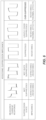
- FIG. 3 illustrates various forms of impedance.
- the resistance form of impedance has a square current signal i(t) that closely resembles the input square voltage signal V(t) - both the voltage and current waveforms are in phase and proportional.
- the capacitance form of impedance has a square current signal i(t) that is lagging as compared to the input square voltage signal V(t) - here the current signal is the derivative of the voltage signal.
- the inductance form of impedance has a current signal i(t) that is leading as compared to the input square voltage signal V(t) - here the current signal is the integral of the voltage signal.
- a relatively small applied voltage waveform V A may be applied to the suppressor in addition to the offset voltage Vas in order to monitor suppressor's current responses to the applied voltage.
- the applied voltage waveform V A is applied in an oscillating square waveform having a frequency F and amplitude A
- the combined offset and applied voltage waveform may be represented as shown in FIG. 4 .
- the measured current response resulting from the offset and applied voltages provides an indication as to the impedance and corresponding operational state of the suppressor.
- the measured current response exhibits a diminishing waveform, as shown in the leftmost measured current response.
- capacitance decreases when the suppressor approaches suppression, the measured current response exhibits a less diminishing waveform, as shown in the second-from-left measured current response.
- the resulting waveform is substantially a square waveform.
- the middle measured current response largely approximates the applied voltage waveform shown in FIG. 4 .
- the impedance is overwhelmingly driven by resistance due to the fact that the eluent is mainly water.
- the measured current response is substantially in phase and proportional to the applied voltage waveform shown in FIG. 4 .
- the power supply may be set to provide an oscillating offset voltage Vas to the suppressor. And the power supply may be activated to provide an applied voltage waveform V A to the suppressor in addition to the offset voltage V OS . An ion chromatography run may then be commenced on the IC system in which eluent flows through the suppressor.
- a current of the suppressor is cyclically measured responsive to the offset and applied voltages V OS and V A , and a suppressor state of the suppressor is determined based upon the measured current waveform.
- Diminishing current corresponding to the upper voltage square waveform may indicate an unsuppressed state of the eluent flowing through the suppressor, which may be due to electrical capacitance and resistance within the suppressor.
- Substantially constant current may indicate a suppressed state, which may be due to substantially constant electrical resistance within the suppressor.
- increasing current corresponding to the upper voltage square waveform may indicate an over-suppressed state, which may be due to increased electrical resistance and thermal effects within the suppressor.
- the offset voltage Vas supplied to the suppressor may be adjusted based upon the suppressor state. Offset voltage V OS may be increased for an unsuppressed state. Offset voltage V OS may be maintained for a suppressed state. And offset voltage V OS may be decreased for an over-suppressed state. Such adjustments may vary the offset voltage V OS over time in response to varied concentration of eluent flowing through the suppressor over time.
- the voltage waveform may have a voltage amplitude A and a voltage frequency F
- the applied voltage waveform V A may be a waveform voltage having a positive pulse width and a negative pulse width.
- an applied square-waveform voltage is utilized to provide readily identifiable positive and negative pulse widths, from which the resulting current response signals would provide readily identifiable current slopes.
- a current slope of a positive pulse width (S P ) less than a first predetermined threshold may indicate an unsuppressed state
- a substantially neutral current slope of the positive pulse width (S P ) greater than the first predetermined threshold and less than a second predetermined threshold may indicate a suppressed state
- a current slope of the positive pulse width (S P ) greater than the second predetermined threshold may indicate an over-suppressed state.
- the applied voltage V A may have a square waveform voltage having a positive pulse width and a negative pulse width.
- the applied voltage V A may be an oscillating voltage having period T, wherein the measuring, determining, and adjusting steps are performed for each period T.
- the measured current response has a positive pulse width slope S P (e.g., slope S P in FIG. 7 ) and a negative pulse width slope S N (e.g., slope S N in FIG. 7 ).
- a slope S P of less than approximately 0.1 mA/s indicates an unsuppressed state
- a slope S P of approximately 0.1 mA/s to 0.3 mA/s indicates a suppressed state
- a slope S P greater than approximately 0.3 mA/s indicates an over-suppressed state
- a slope S N greater than approximately -0.05 mA/s indicates an unsuppressed state
- a slope S N less than approximately -0.05 indicates a suppressed or over-suppressed state.
- An adjusting step may adjust the offset voltage V OS by an adjusted voltage ⁇ V each period T.
- the adjusted voltage ⁇ V is less than the applied voltage V A .
- the adjusted voltage ⁇ V is less than 10% of the Amplitude A.
- the adjusted voltage ⁇ V may be approximately 5 mV.
- a ⁇ V of approximately 0.01 to 10% of the Amplitude A may efficiently adjust the voltage while avoiding overcorrection.
- the power supply and control unit may be configured in various ways to apply offset voltages V OS and applied voltage waveforms V A to the suppressor, and to measure the current of the suppressor response to the offset and applied voltages V OS , V A .
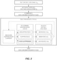
- the power supply and control unit may be configured to execute a repeat-cycle program similar to that illustrated in FIG. 6 .
- a program allows the self-adjustment of the offset voltage provided to the suppressor based on the current response of the suppressor, thereby creating a self-regulating feedback loop.
- the program may generally run as follows:
- the power supply and control unit may be configured to operate the suppressor.
- various protocols and parameters may be utilized to apply predetermined operating voltages (i.e., offset voltage V OS ) and observable applied voltage waveforms (i.e., applied voltage V A ) to the suppressor and measure the resulting current of the suppressor in order to self-regulate the suppressor.
- predetermined operating voltages i.e., offset voltage V OS
- observable applied voltage waveforms i.e., applied voltage V A
- the upper or the lower slope e.g., slopes S P and S N in FIG. 7
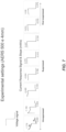
- the following parameters were used for applying a square waveform voltage to a Dionex TM AERS TM 500 4mm suppressor: cycle time of 10 seconds; frequency of 0.1 Hz; amplitude of 100 mV; and a delta voltage ⁇ V of +/- 5 mV (i.e., the amount by which the offset voltage is changed each cycle time every 10 seconds).
- cycle time 10 seconds
- frequency of 0.1 Hz amplitude of 100 mV
- a delta voltage ⁇ V i.e., the amount by which the offset voltage is changed each cycle time every 10 seconds.
- the current response is shown in FIG. 7 , and it can be seen that diminishing measured current response signals indicate unsuppressed states of the suppressor, negligible slopes indicate suppressed states, and increasing wave signals indicate over-suppressed states.
- upper and lower slope criteria of the measured current response signals may be defined to distinguish each suppressor state.
- the following table sets forth slope criteria that may be utilized to distinguish each suppressor state. Slope (mA/s) Criteria Upper (or S P ) Lower (or S N ) Unsuppressed ⁇ 0.100 > -0.050 Suppressed 0.100 - 0.300 ⁇ -0.050 Over-Suppressed > 0.300 ⁇ -0.050
- the unsuppressed state may be identified when the upper slope (e.g., S P in FIG. 7 ) is below approximately 0.100 mA/s, the suppressed state when the upper slope is approximately 0.100 to 0.300 mA/s, and the over-suppressed state when the upper slope is above approximately 0.300 mA/s.
- the unsuppressed state may also be identified when the lower slope (e.g., S N ) is above approximately -0.050 mA/s.
- the power supply may regulate voltage to the suppressor as follows:
- the upper slope alone (e.g., S P in FIG. 7 ) may be capable of identifying the unsuppressed, suppressed, and over-suppressed states of the suppressor.
- the lower slope alone (e.g., S N in FIG. 7 ) may be capable of identifying whether or not the suppressor is unsuppressed.
- both slopes may be utilized together to identify the three suppressor states.
- the systems and methods described herein may provide simpler equipment configurations as desired voltages for the suppressor are determined without any feedback from the conductivity detector. In fact, the systems and methods described herein may provide desired voltages to the suppressor without knowledge of eluent concentrations and/or flow rates through the suppressor.
- the systems and methods described herein allow for automatically voltage changes to the suppressor. For example, as eluent concentration through the suppressor increases, a constant voltage to the suppressor would result in under-suppression of the greater eluent concentration.
- the present systems and methods allow for identifying such an unsuppressed state and automatically take corrective action.
- a power supply and/or control unit may be readily retrofit to existing IC systems.
Landscapes
- Chemical & Material Sciences (AREA)
- Analytical Chemistry (AREA)
- Physics & Mathematics (AREA)
- Health & Medical Sciences (AREA)
- Life Sciences & Earth Sciences (AREA)
- Biochemistry (AREA)
- General Health & Medical Sciences (AREA)
- General Physics & Mathematics (AREA)
- Immunology (AREA)
- Pathology (AREA)
- Chemical Kinetics & Catalysis (AREA)
- Investigating Or Analyzing Materials By The Use Of Electric Means (AREA)
Applications Claiming Priority (1)
| Application Number | Priority Date | Filing Date | Title |
|---|---|---|---|
| US17/558,464 US11860143B2 (en) | 2021-12-21 | 2021-12-21 | Method and system for self-regulating a suppressor |
Publications (2)
| Publication Number | Publication Date |
|---|---|
| EP4201499A1 true EP4201499A1 (de) | 2023-06-28 |
| EP4201499B1 EP4201499B1 (de) | 2025-08-13 |
Family
ID=84536154
Family Applications (1)
| Application Number | Title | Priority Date | Filing Date |
|---|---|---|---|
| EP22213415.7A Active EP4201499B1 (de) | 2021-12-21 | 2022-12-14 | Verfahren und system zur selbstregulierung eines suppressors |
Country Status (4)
| Country | Link |
|---|---|
| US (1) | US11860143B2 (de) |
| EP (1) | EP4201499B1 (de) |
| JP (1) | JP7490171B2 (de) |
| CN (1) | CN116298056A (de) |
Families Citing this family (1)
| Publication number | Priority date | Publication date | Assignee | Title |
|---|---|---|---|---|
| US12474310B2 (en) * | 2022-11-30 | 2025-11-18 | Dionex Corporation | Suppressor diagnostic tool |
Citations (13)
| Publication number | Priority date | Publication date | Assignee | Title |
|---|---|---|---|---|
| US3897213A (en) | 1973-08-06 | 1975-07-29 | Dow Chemical Co | Automated quantitative analysis of ionic species |
| US3920397A (en) | 1973-08-06 | 1975-11-18 | Dow Chemical Co | Apparatus and method for quantitative analysis of ionic species by liquid column chromatography |
| US3925019A (en) | 1973-08-06 | 1975-12-09 | Dow Chemical Co | Chromatographic analysis of ionic species |
| US3926559A (en) | 1973-08-06 | 1975-12-16 | Dow Chemical Co | Method and apparatus for quantitative chromatographic analysis of cationic species |
| US4403039A (en) | 1980-10-29 | 1983-09-06 | Yokogawa Hokushin Electric Works | Method and apparatus for analysis of ionic species |
| US4459357A (en) | 1981-07-08 | 1984-07-10 | Jansen Karl Heinz | Process and apparatus for the quantitative determination of cations or anions by ion chromatography |
| US4474664A (en) | 1980-01-16 | 1984-10-02 | The Dow Chemical Company | Ion analysis method and apparatus |
| US4999098A (en) | 1984-10-04 | 1991-03-12 | Dionex Corporation | Modified membrane suppressor and method for use |
| US5248426A (en) | 1992-02-10 | 1993-09-28 | Dionex Corporation | Ion chromatography system using electrochemical suppression and detector effluent recycle |
| US5597734A (en) | 1993-08-27 | 1997-01-28 | Dionex Corporation | Ion chromatography using frequent regeneration of batch-type suppressor |
| WO2000042426A1 (en) * | 1999-01-15 | 2000-07-20 | Dionex Corporation | Current-efficient suppressors and method of use |
| US20100284861A1 (en) * | 2008-01-07 | 2010-11-11 | Shigeyoshi Horiike | Suppressor and ion chromatograph employing the same |
| EP1299717B1 (de) * | 2000-07-07 | 2014-10-08 | Dionex Corporation | Kombination aus elektrolytischem suppressor und separatem eluentgenerator |
Family Cites Families (36)
| Publication number | Priority date | Publication date | Assignee | Title |
|---|---|---|---|---|
| US3966596A (en) * | 1973-08-06 | 1976-06-29 | The Dow Chemical Company | High performance, cation-exchange chromatography on surface-sulfonated compositions |
| US4017262A (en) * | 1973-08-06 | 1977-04-12 | The Dow Chemical Company | Chromatographic apparatus for analysis of ionic species |
| US4042499A (en) * | 1976-08-02 | 1977-08-16 | The Dow Chemical Company | Liquid adsorption chromatographic apparatus and method |
| US4672322A (en) * | 1984-08-24 | 1987-06-09 | Milton Roy Company | High sensitivity conductivity detector |
| US4861555A (en) * | 1985-03-11 | 1989-08-29 | Applied Automation, Inc. | Apparatus for chromatographic analysis of ionic species |
| GB2226135A (en) * | 1988-12-15 | 1990-06-20 | Forex Neptune Sa | Monitoring ions present in drilling muds or fluids |
| US4925567A (en) * | 1989-03-02 | 1990-05-15 | Basf Corporation | Baseline stabiilty in gradient ion chromatography by using a nonionic modifier |
| US5045204A (en) * | 1990-02-13 | 1991-09-03 | Dionex Corporation | Method and apparatus for generating a high purity chromatography eluent |
| ATE196949T1 (de) * | 1995-03-03 | 2000-10-15 | Alltech Associates Inc | Verfahren und vorrichtung zur elektrochemischen veränderung von chromatographiematerial |
| US6200477B1 (en) | 1998-05-06 | 2001-03-13 | Alltech Associates, Inc. | Continuously regenerated and integrated suppressor and detector for suppressed ion chromatography and method |
| CA2426571A1 (en) * | 2000-11-01 | 2002-05-10 | Eleftherios P. Diamandis | Detection of ovarian cancer |
| US6752927B2 (en) * | 2001-03-01 | 2004-06-22 | Dionex Corporation | Suppressed chromatography and salt conversion system |
| AU2003266038A1 (en) * | 2002-08-28 | 2004-03-19 | Mount Sinai Hospital | Methods for detecting endocrine cancer using kallikrein 13 (klk13) as a biomarker |
| US8037902B2 (en) * | 2003-05-19 | 2011-10-18 | Protasis Corporation | Fluid logic device |
| US8101422B2 (en) * | 2005-09-16 | 2012-01-24 | Dionex Corporation | Multidimensional chromatography apparatus and method |
| US8293099B2 (en) * | 2008-02-28 | 2012-10-23 | Dionex Corporation | Ion detector and system |
| EP2444990B1 (de) * | 2010-10-19 | 2014-06-25 | ICT Integrated Circuit Testing Gesellschaft für Halbleiterprüftechnik mbH | Vereinfachter Partikelemitter und Betriebsverfahren dafür |
| WO2012170078A2 (en) * | 2011-06-08 | 2012-12-13 | Lc Sciences | Peptide capture and characterization |
| JP5990956B2 (ja) | 2012-03-21 | 2016-09-14 | 株式会社島津製作所 | サプレッサ及びそれを用いたイオンクロマトグラフ |
| US10048233B2 (en) * | 2012-11-12 | 2018-08-14 | Dionex Corporation | Suppressor device |
| US11090606B2 (en) * | 2013-12-05 | 2021-08-17 | Dionex Corporation | Gas-less electrolytic device and method |
| US10175211B2 (en) * | 2014-12-31 | 2019-01-08 | Dionex Corporation | Current-efficient suppressor and pretreatment device and method |
| US10228355B2 (en) * | 2016-05-06 | 2019-03-12 | Board Of Regents, The University Of Texas System | Volatile eluent preparation |
| US10416137B2 (en) * | 2016-09-07 | 2019-09-17 | Board Of Regents, University Of Texas System | Electrodialytic capillary suppressor for suppressed conductometric ion chromatography |
| EP3545296B1 (de) * | 2016-11-28 | 2025-06-25 | Board of Regents, The University of Texas System | Systeme, verfahren und vorrichtungen zur breitenbasierten analyse von spitzenspuren |
| CN106645472A (zh) * | 2016-12-08 | 2017-05-10 | 同方威视技术股份有限公司 | 气相色谱‑离子迁移谱设备 |
| JP6751446B2 (ja) * | 2017-01-06 | 2020-09-02 | 富士フイルム株式会社 | 薬液の品質検査方法 |
| JP6809594B2 (ja) * | 2017-02-20 | 2021-01-06 | 株式会社島津製作所 | 電気伝導度検出器及びイオンクロマトグラフ |
| CN110637230B (zh) * | 2017-07-24 | 2022-06-24 | 株式会社岛津制作所 | 离子抑制器及离子色谱仪 |
| JP6897772B2 (ja) * | 2017-07-24 | 2021-07-07 | 株式会社島津製作所 | イオンサプレッサーおよびイオンクロマトグラフ |
| US11105782B2 (en) | 2017-10-10 | 2021-08-31 | Dionex Corporation | Fast startup ion chromatography system and methods |
| US12031957B2 (en) * | 2019-03-27 | 2024-07-09 | Shimadzu Corporation | Ion suppressor |
| US11982653B2 (en) * | 2019-04-01 | 2024-05-14 | Shimadzu Corporation | Ion chromatograph and ion component analysis method |
| JP7260000B2 (ja) * | 2020-01-08 | 2023-04-18 | 株式会社島津製作所 | イオンクロマトグラフ用サプレッサ装置 |
| JP7468388B2 (ja) * | 2021-02-02 | 2024-04-16 | 株式会社島津製作所 | 液体クロマトグラフ用検出器 |
| JP7468389B2 (ja) * | 2021-02-03 | 2024-04-16 | 株式会社島津製作所 | 液体クロマトグラフ用検出器 |
-
2021
- 2021-12-21 US US17/558,464 patent/US11860143B2/en active Active
-
2022
- 2022-12-14 EP EP22213415.7A patent/EP4201499B1/de active Active
- 2022-12-20 CN CN202211643144.XA patent/CN116298056A/zh active Pending
- 2022-12-21 JP JP2022204190A patent/JP7490171B2/ja active Active
Patent Citations (14)
| Publication number | Priority date | Publication date | Assignee | Title |
|---|---|---|---|---|
| US3897213A (en) | 1973-08-06 | 1975-07-29 | Dow Chemical Co | Automated quantitative analysis of ionic species |
| US3920397A (en) | 1973-08-06 | 1975-11-18 | Dow Chemical Co | Apparatus and method for quantitative analysis of ionic species by liquid column chromatography |
| US3925019A (en) | 1973-08-06 | 1975-12-09 | Dow Chemical Co | Chromatographic analysis of ionic species |
| US3926559A (en) | 1973-08-06 | 1975-12-16 | Dow Chemical Co | Method and apparatus for quantitative chromatographic analysis of cationic species |
| US4474664A (en) | 1980-01-16 | 1984-10-02 | The Dow Chemical Company | Ion analysis method and apparatus |
| US4403039A (en) | 1980-10-29 | 1983-09-06 | Yokogawa Hokushin Electric Works | Method and apparatus for analysis of ionic species |
| US4459357A (en) | 1981-07-08 | 1984-07-10 | Jansen Karl Heinz | Process and apparatus for the quantitative determination of cations or anions by ion chromatography |
| US4999098A (en) | 1984-10-04 | 1991-03-12 | Dionex Corporation | Modified membrane suppressor and method for use |
| US5248426A (en) | 1992-02-10 | 1993-09-28 | Dionex Corporation | Ion chromatography system using electrochemical suppression and detector effluent recycle |
| US5352360A (en) | 1992-02-10 | 1994-10-04 | Dionex Corporation | Ion chromatography system using electrochemical suppression and detector effluent recycle |
| US5597734A (en) | 1993-08-27 | 1997-01-28 | Dionex Corporation | Ion chromatography using frequent regeneration of batch-type suppressor |
| WO2000042426A1 (en) * | 1999-01-15 | 2000-07-20 | Dionex Corporation | Current-efficient suppressors and method of use |
| EP1299717B1 (de) * | 2000-07-07 | 2014-10-08 | Dionex Corporation | Kombination aus elektrolytischem suppressor und separatem eluentgenerator |
| US20100284861A1 (en) * | 2008-01-07 | 2010-11-11 | Shigeyoshi Horiike | Suppressor and ion chromatograph employing the same |
Non-Patent Citations (1)
| Title |
|---|
| VALENTIN-BLASINI ET AL: "Quantification of iodide and sodium-iodide symporter inhibitors in human urine using ion chromatography tandem mass spectrometry", JOURNAL OF CHROMATOGRAPHY A, ELSEVIER, AMSTERDAM, NL, vol. 1155, no. 1, 7 June 2007 (2007-06-07), pages 40 - 46, XP022109222, ISSN: 0021-9673, DOI: 10.1016/J.CHROMA.2007.04.014 * |
Also Published As
| Publication number | Publication date |
|---|---|
| JP2023092525A (ja) | 2023-07-03 |
| EP4201499B1 (de) | 2025-08-13 |
| JP7490171B2 (ja) | 2024-05-27 |
| US20230194484A1 (en) | 2023-06-22 |
| CN116298056A (zh) | 2023-06-23 |
| US11860143B2 (en) | 2024-01-02 |
Similar Documents
| Publication | Publication Date | Title |
|---|---|---|
| JP3104247B2 (ja) | 電気化学検出器 | |
| EP4201499A1 (de) | Verfahren und system zur selbstregulierung eines suppressors | |
| EP1107817B1 (de) | Kontinuierlich regenerierter integrierter suppressor sowie detektor und verfahren zur suppressor-ionenchromatographie | |
| Masár et al. | Conductivity detection and quantitation of isotachophoretic analytes on a planar chip with on-line coupled separation channels | |
| WO2020098361A1 (zh) | 双铂电极式高锰酸盐指数在线分析仪滴定终点指示装置 | |
| Křivánková et al. | Analysis of ethyl glucuronide in human serum by capillary electrophoresis with sample self-stacking and indirect detection | |
| Martınez et al. | Capillary zone electrophoresis with indirect UV detection of haloacetic acids in water | |
| Small et al. | Electrically polarized ion-exchange beds in ion chromatography: eluent generation and recycling | |
| KR20100138949A (ko) | 용리액 재순환을 동반하는 이온 크로마토그래피 시스템 | |
| KR101829405B1 (ko) | 전기탈이온 제어 시스템 | |
| EP3177915B1 (de) | Verfahren zur reduzierung des suppressorrauschens | |
| Saari-Nordhaus et al. | Recent advances in ion chromatography suppressor improve anion separation and detection | |
| Malá et al. | Methodology of analysis of very weak acids by isotachophoresis with electrospray-ionization mass-spectrometric detection: Anionic electrolyte systems for the medium-alkaline pH range | |
| JPS6011690A (ja) | 液体クロマトグラフ | |
| JP2024035932A (ja) | イオンクロマトグラフィ分析システム | |
| JP3135211U (ja) | イオンクロマトグラフ | |
| JP3299362B2 (ja) | 液体クロマトグラフィーのグラジエント分析方法および装置 | |
| EP4375660A1 (de) | Verbesserte chromatografie-grundlinienstabilität | |
| Avdalovic et al. | Capillary ion chromatography | |
| JP2007033232A (ja) | 濃縮イオンクロマトグラフ測定方法および濃縮イオンクロマトグラフ測定装置 | |
| Deelder et al. | A potentiometric membrane cell as a detector in liquid chromatography | |
| JP2005195489A (ja) | 液体クロマトグラフ装置およびこれによるアルコール類および糖類の分析方法 | |
| Šlais | Simultaneous conductivity and potentiometric detector for miniaturized liquid chromatography and flow analysis | |
| US12540929B2 (en) | Desalting system for chromatography | |
| EP4270003A1 (de) | Überwachung und abschwächung von suppressorfehlern |
Legal Events
| Date | Code | Title | Description |
|---|---|---|---|
| PUAI | Public reference made under article 153(3) epc to a published international application that has entered the european phase |
Free format text: ORIGINAL CODE: 0009012 |
|
| STAA | Information on the status of an ep patent application or granted ep patent |
Free format text: STATUS: THE APPLICATION HAS BEEN PUBLISHED |
|
| AK | Designated contracting states |
Kind code of ref document: A1 Designated state(s): AL AT BE BG CH CY CZ DE DK EE ES FI FR GB GR HR HU IE IS IT LI LT LU LV MC ME MK MT NL NO PL PT RO RS SE SI SK SM TR |
|
| STAA | Information on the status of an ep patent application or granted ep patent |
Free format text: STATUS: REQUEST FOR EXAMINATION WAS MADE |
|
| 17P | Request for examination filed |
Effective date: 20231004 |
|
| RBV | Designated contracting states (corrected) |
Designated state(s): AL AT BE BG CH CY CZ DE DK EE ES FI FR GB GR HR HU IE IS IT LI LT LU LV MC ME MK MT NL NO PL PT RO RS SE SI SK SM TR |
|
| GRAP | Despatch of communication of intention to grant a patent |
Free format text: ORIGINAL CODE: EPIDOSNIGR1 |
|
| STAA | Information on the status of an ep patent application or granted ep patent |
Free format text: STATUS: GRANT OF PATENT IS INTENDED |
|
| INTG | Intention to grant announced |
Effective date: 20250310 |
|
| GRAS | Grant fee paid |
Free format text: ORIGINAL CODE: EPIDOSNIGR3 |
|
| GRAA | (expected) grant |
Free format text: ORIGINAL CODE: 0009210 |
|
| STAA | Information on the status of an ep patent application or granted ep patent |
Free format text: STATUS: THE PATENT HAS BEEN GRANTED |
|
| AK | Designated contracting states |
Kind code of ref document: B1 Designated state(s): AL AT BE BG CH CY CZ DE DK EE ES FI FR GB GR HR HU IE IS IT LI LT LU LV MC ME MK MT NL NO PL PT RO RS SE SI SK SM TR |
|
| REG | Reference to a national code |
Ref country code: GB Ref legal event code: FG4D |
|
| REG | Reference to a national code |
Ref country code: CH Ref legal event code: EP |
|
| REG | Reference to a national code |
Ref country code: DE Ref legal event code: R096 Ref document number: 602022019345 Country of ref document: DE |
|
| REG | Reference to a national code |
Ref country code: IE Ref legal event code: FG4D |
|
| REG | Reference to a national code |
Ref country code: NL Ref legal event code: MP Effective date: 20250813 |
|
| REG | Reference to a national code |
Ref country code: CH Ref legal event code: U11 Free format text: ST27 STATUS EVENT CODE: U-0-0-U10-U11 (AS PROVIDED BY THE NATIONAL OFFICE) Effective date: 20260101 |
|
| PG25 | Lapsed in a contracting state [announced via postgrant information from national office to epo] |
Ref country code: IS Free format text: LAPSE BECAUSE OF FAILURE TO SUBMIT A TRANSLATION OF THE DESCRIPTION OR TO PAY THE FEE WITHIN THE PRESCRIBED TIME-LIMIT Effective date: 20251213 |
|
| PGFP | Annual fee paid to national office [announced via postgrant information from national office to epo] |
Ref country code: DE Payment date: 20251113 Year of fee payment: 4 |
|
| PG25 | Lapsed in a contracting state [announced via postgrant information from national office to epo] |
Ref country code: NO Free format text: LAPSE BECAUSE OF FAILURE TO SUBMIT A TRANSLATION OF THE DESCRIPTION OR TO PAY THE FEE WITHIN THE PRESCRIBED TIME-LIMIT Effective date: 20251113 |
|
| REG | Reference to a national code |
Ref country code: LT Ref legal event code: MG9D |
|
| PG25 | Lapsed in a contracting state [announced via postgrant information from national office to epo] |
Ref country code: PT Free format text: LAPSE BECAUSE OF FAILURE TO SUBMIT A TRANSLATION OF THE DESCRIPTION OR TO PAY THE FEE WITHIN THE PRESCRIBED TIME-LIMIT Effective date: 20251215 |
|
| PG25 | Lapsed in a contracting state [announced via postgrant information from national office to epo] |
Ref country code: FI Free format text: LAPSE BECAUSE OF FAILURE TO SUBMIT A TRANSLATION OF THE DESCRIPTION OR TO PAY THE FEE WITHIN THE PRESCRIBED TIME-LIMIT Effective date: 20250813 |
|
| PG25 | Lapsed in a contracting state [announced via postgrant information from national office to epo] |
Ref country code: HR Free format text: LAPSE BECAUSE OF FAILURE TO SUBMIT A TRANSLATION OF THE DESCRIPTION OR TO PAY THE FEE WITHIN THE PRESCRIBED TIME-LIMIT Effective date: 20250813 Ref country code: NL Free format text: LAPSE BECAUSE OF FAILURE TO SUBMIT A TRANSLATION OF THE DESCRIPTION OR TO PAY THE FEE WITHIN THE PRESCRIBED TIME-LIMIT Effective date: 20250813 |
|
| PG25 | Lapsed in a contracting state [announced via postgrant information from national office to epo] |
Ref country code: GR Free format text: LAPSE BECAUSE OF FAILURE TO SUBMIT A TRANSLATION OF THE DESCRIPTION OR TO PAY THE FEE WITHIN THE PRESCRIBED TIME-LIMIT Effective date: 20251114 |
|
| PG25 | Lapsed in a contracting state [announced via postgrant information from national office to epo] |
Ref country code: SE Free format text: LAPSE BECAUSE OF FAILURE TO SUBMIT A TRANSLATION OF THE DESCRIPTION OR TO PAY THE FEE WITHIN THE PRESCRIBED TIME-LIMIT Effective date: 20250813 |
|
| PG25 | Lapsed in a contracting state [announced via postgrant information from national office to epo] |
Ref country code: LV Free format text: LAPSE BECAUSE OF FAILURE TO SUBMIT A TRANSLATION OF THE DESCRIPTION OR TO PAY THE FEE WITHIN THE PRESCRIBED TIME-LIMIT Effective date: 20250813 |
|
| PG25 | Lapsed in a contracting state [announced via postgrant information from national office to epo] |
Ref country code: BG Free format text: LAPSE BECAUSE OF FAILURE TO SUBMIT A TRANSLATION OF THE DESCRIPTION OR TO PAY THE FEE WITHIN THE PRESCRIBED TIME-LIMIT Effective date: 20250813 Ref country code: PL Free format text: LAPSE BECAUSE OF FAILURE TO SUBMIT A TRANSLATION OF THE DESCRIPTION OR TO PAY THE FEE WITHIN THE PRESCRIBED TIME-LIMIT Effective date: 20250813 |
|
| PG25 | Lapsed in a contracting state [announced via postgrant information from national office to epo] |
Ref country code: RS Free format text: LAPSE BECAUSE OF FAILURE TO SUBMIT A TRANSLATION OF THE DESCRIPTION OR TO PAY THE FEE WITHIN THE PRESCRIBED TIME-LIMIT Effective date: 20251113 |
|
| PG25 | Lapsed in a contracting state [announced via postgrant information from national office to epo] |
Ref country code: ES Free format text: LAPSE BECAUSE OF FAILURE TO SUBMIT A TRANSLATION OF THE DESCRIPTION OR TO PAY THE FEE WITHIN THE PRESCRIBED TIME-LIMIT Effective date: 20250813 |