EP4197858A1 - Stossabsorbierendes fahrzeugscheinwerfersystem - Google Patents
Stossabsorbierendes fahrzeugscheinwerfersystem Download PDFInfo
- Publication number
- EP4197858A1 EP4197858A1 EP21215092.4A EP21215092A EP4197858A1 EP 4197858 A1 EP4197858 A1 EP 4197858A1 EP 21215092 A EP21215092 A EP 21215092A EP 4197858 A1 EP4197858 A1 EP 4197858A1
- Authority
- EP
- European Patent Office
- Prior art keywords
- vehicle
- pin
- vehicle headlight
- rotary arm
- triggering
- Prior art date
- Legal status (The legal status is an assumption and is not a legal conclusion. Google has not performed a legal analysis and makes no representation as to the accuracy of the status listed.)
- Granted
Links
Images

Classifications
-
- B—PERFORMING OPERATIONS; TRANSPORTING
- B60—VEHICLES IN GENERAL
- B60Q—ARRANGEMENT OF SIGNALLING OR LIGHTING DEVICES, THE MOUNTING OR SUPPORTING THEREOF OR CIRCUITS THEREFOR, FOR VEHICLES IN GENERAL
- B60Q1/00—Arrangement of optical signalling or lighting devices, the mounting or supporting thereof or circuits therefor
- B60Q1/02—Arrangement of optical signalling or lighting devices, the mounting or supporting thereof or circuits therefor the devices being primarily intended to illuminate the way ahead or to illuminate other areas of way or environments
- B60Q1/04—Arrangement of optical signalling or lighting devices, the mounting or supporting thereof or circuits therefor the devices being primarily intended to illuminate the way ahead or to illuminate other areas of way or environments the devices being headlights
- B60Q1/0491—Shock absorbing devices therefor
-
- B—PERFORMING OPERATIONS; TRANSPORTING
- B60—VEHICLES IN GENERAL
- B60Q—ARRANGEMENT OF SIGNALLING OR LIGHTING DEVICES, THE MOUNTING OR SUPPORTING THEREOF OR CIRCUITS THEREFOR, FOR VEHICLES IN GENERAL
- B60Q1/00—Arrangement of optical signalling or lighting devices, the mounting or supporting thereof or circuits therefor
- B60Q1/0017—Devices integrating an element dedicated to another function
- B60Q1/0023—Devices integrating an element dedicated to another function the element being a sensor, e.g. distance sensor, camera
-
- B—PERFORMING OPERATIONS; TRANSPORTING
- B60—VEHICLES IN GENERAL
- B60Q—ARRANGEMENT OF SIGNALLING OR LIGHTING DEVICES, THE MOUNTING OR SUPPORTING THEREOF OR CIRCUITS THEREFOR, FOR VEHICLES IN GENERAL
- B60Q1/00—Arrangement of optical signalling or lighting devices, the mounting or supporting thereof or circuits therefor
- B60Q1/02—Arrangement of optical signalling or lighting devices, the mounting or supporting thereof or circuits therefor the devices being primarily intended to illuminate the way ahead or to illuminate other areas of way or environments
- B60Q1/04—Arrangement of optical signalling or lighting devices, the mounting or supporting thereof or circuits therefor the devices being primarily intended to illuminate the way ahead or to illuminate other areas of way or environments the devices being headlights
- B60Q1/0408—Arrangement of optical signalling or lighting devices, the mounting or supporting thereof or circuits therefor the devices being primarily intended to illuminate the way ahead or to illuminate other areas of way or environments the devices being headlights built into the vehicle body, e.g. details concerning the mounting of the headlamps on the vehicle body
-
- B—PERFORMING OPERATIONS; TRANSPORTING
- B60—VEHICLES IN GENERAL
- B60Q—ARRANGEMENT OF SIGNALLING OR LIGHTING DEVICES, THE MOUNTING OR SUPPORTING THEREOF OR CIRCUITS THEREFOR, FOR VEHICLES IN GENERAL
- B60Q1/00—Arrangement of optical signalling or lighting devices, the mounting or supporting thereof or circuits therefor
- B60Q1/02—Arrangement of optical signalling or lighting devices, the mounting or supporting thereof or circuits therefor the devices being primarily intended to illuminate the way ahead or to illuminate other areas of way or environments
- B60Q1/04—Arrangement of optical signalling or lighting devices, the mounting or supporting thereof or circuits therefor the devices being primarily intended to illuminate the way ahead or to illuminate other areas of way or environments the devices being headlights
- B60Q1/0408—Arrangement of optical signalling or lighting devices, the mounting or supporting thereof or circuits therefor the devices being primarily intended to illuminate the way ahead or to illuminate other areas of way or environments the devices being headlights built into the vehicle body, e.g. details concerning the mounting of the headlamps on the vehicle body
- B60Q1/0441—Arrangement of optical signalling or lighting devices, the mounting or supporting thereof or circuits therefor the devices being primarily intended to illuminate the way ahead or to illuminate other areas of way or environments the devices being headlights built into the vehicle body, e.g. details concerning the mounting of the headlamps on the vehicle body the housing being fastened onto the vehicle body using means other than screws
-
- B—PERFORMING OPERATIONS; TRANSPORTING
- B60—VEHICLES IN GENERAL
- B60Q—ARRANGEMENT OF SIGNALLING OR LIGHTING DEVICES, THE MOUNTING OR SUPPORTING THEREOF OR CIRCUITS THEREFOR, FOR VEHICLES IN GENERAL
- B60Q1/00—Arrangement of optical signalling or lighting devices, the mounting or supporting thereof or circuits therefor
- B60Q1/02—Arrangement of optical signalling or lighting devices, the mounting or supporting thereof or circuits therefor the devices being primarily intended to illuminate the way ahead or to illuminate other areas of way or environments
- B60Q1/04—Arrangement of optical signalling or lighting devices, the mounting or supporting thereof or circuits therefor the devices being primarily intended to illuminate the way ahead or to illuminate other areas of way or environments the devices being headlights
- B60Q1/0483—Arrangement of optical signalling or lighting devices, the mounting or supporting thereof or circuits therefor the devices being primarily intended to illuminate the way ahead or to illuminate other areas of way or environments the devices being headlights mounted on a bracket, e.g. details concerning the mouting of the lamps on the vehicle body
-
- B—PERFORMING OPERATIONS; TRANSPORTING
- B60—VEHICLES IN GENERAL
- B60Q—ARRANGEMENT OF SIGNALLING OR LIGHTING DEVICES, THE MOUNTING OR SUPPORTING THEREOF OR CIRCUITS THEREFOR, FOR VEHICLES IN GENERAL
- B60Q1/00—Arrangement of optical signalling or lighting devices, the mounting or supporting thereof or circuits therefor
- B60Q1/02—Arrangement of optical signalling or lighting devices, the mounting or supporting thereof or circuits therefor the devices being primarily intended to illuminate the way ahead or to illuminate other areas of way or environments
- B60Q1/04—Arrangement of optical signalling or lighting devices, the mounting or supporting thereof or circuits therefor the devices being primarily intended to illuminate the way ahead or to illuminate other areas of way or environments the devices being headlights
- B60Q1/06—Arrangement of optical signalling or lighting devices, the mounting or supporting thereof or circuits therefor the devices being primarily intended to illuminate the way ahead or to illuminate other areas of way or environments the devices being headlights adjustable, e.g. remotely-controlled from inside vehicle
- B60Q1/08—Arrangement of optical signalling or lighting devices, the mounting or supporting thereof or circuits therefor the devices being primarily intended to illuminate the way ahead or to illuminate other areas of way or environments the devices being headlights adjustable, e.g. remotely-controlled from inside vehicle automatically
- B60Q1/10—Arrangement of optical signalling or lighting devices, the mounting or supporting thereof or circuits therefor the devices being primarily intended to illuminate the way ahead or to illuminate other areas of way or environments the devices being headlights adjustable, e.g. remotely-controlled from inside vehicle automatically due to vehicle inclination, e.g. due to load distribution
- B60Q1/115—Arrangement of optical signalling or lighting devices, the mounting or supporting thereof or circuits therefor the devices being primarily intended to illuminate the way ahead or to illuminate other areas of way or environments the devices being headlights adjustable, e.g. remotely-controlled from inside vehicle automatically due to vehicle inclination, e.g. due to load distribution by electric means
-
- B—PERFORMING OPERATIONS; TRANSPORTING
- B60—VEHICLES IN GENERAL
- B60R—VEHICLES, VEHICLE FITTINGS, OR VEHICLE PARTS, NOT OTHERWISE PROVIDED FOR
- B60R21/00—Arrangements or fittings on vehicles for protecting or preventing injuries to occupants or pedestrians in case of accidents or other traffic risks
- B60R21/34—Protecting non-occupants of a vehicle, e.g. pedestrians
-
- F—MECHANICAL ENGINEERING; LIGHTING; HEATING; WEAPONS; BLASTING
- F21—LIGHTING
- F21S—NON-PORTABLE LIGHTING DEVICES; SYSTEMS THEREOF; VEHICLE LIGHTING DEVICES SPECIALLY ADAPTED FOR VEHICLE EXTERIORS
- F21S41/00—Illuminating devices specially adapted for vehicle exteriors, e.g. headlamps
- F21S41/10—Illuminating devices specially adapted for vehicle exteriors, e.g. headlamps characterised by the light source
- F21S41/19—Attachment of light sources or lamp holders
- F21S41/196—Wire spring attachments
-
- B—PERFORMING OPERATIONS; TRANSPORTING
- B60—VEHICLES IN GENERAL
- B60Q—ARRANGEMENT OF SIGNALLING OR LIGHTING DEVICES, THE MOUNTING OR SUPPORTING THEREOF OR CIRCUITS THEREFOR, FOR VEHICLES IN GENERAL
- B60Q2300/00—Indexing codes for automatically adjustable headlamps or automatically dimmable headlamps
- B60Q2300/10—Indexing codes relating to particular vehicle conditions
- B60Q2300/14—Other vehicle conditions
- B60Q2300/146—Abnormalities, e.g. fail-safe
-
- B—PERFORMING OPERATIONS; TRANSPORTING
- B60—VEHICLES IN GENERAL
- B60R—VEHICLES, VEHICLE FITTINGS, OR VEHICLE PARTS, NOT OTHERWISE PROVIDED FOR
- B60R21/00—Arrangements or fittings on vehicles for protecting or preventing injuries to occupants or pedestrians in case of accidents or other traffic risks
- B60R21/34—Protecting non-occupants of a vehicle, e.g. pedestrians
- B60R2021/343—Protecting non-occupants of a vehicle, e.g. pedestrians using deformable body panel, bodywork or components
Definitions
- the invention relates to a shock-absorbing vehicle headlight system, having at least one vehicle frame element that can be firmly connected to a vehicle, a vehicle headlight housing that is held displaceably on the vehicle frame element and has at least one pin connected to the vehicle headlight housing, which is preferably firmly connected to the vehicle headlight housing, the vehicle frame element having at least one guide for receiving and linear guidance of the pin, the pin being in engagement with the guide so that the vehicle headlight housing is guided along the guide by displacement of the pin and can thereby be displaced in relation to the vehicle frame element, at least one triggering element which can be mechanically connected to a bumper of a vehicle, and at least one release mechanism fixedly connected to the vehicle frame element, which is set up to receive the release element and the pin and to switch between a state blocking the pin and a state releasing the pin, at least depending on the position of the release element, with the state releasing the pin the vehicle headlight housing can be displaced together with the pin in relation to the vehicle frame element.
- Impact-absorbing vehicle headlights are used to protect pedestrians, since in the event of a collision, impact energy can be absorbed by shifting the vehicle headlights.
- document EP1332915 B1 shows a prior art shock absorbing vehicle headlamp.
- One object of the invention is therefore to create an impact-absorbing vehicle headlight system which offers reliable protection for pedestrians and at the same time has a high perceived value.
- the triggering mechanism comprises the following: A rotary arm which is rotatably mounted in the triggering mechanism and which rotary arm has an engagement area for receiving the pin, the rotary arm being set up to be rotated between two positions to be, namely between a holding position in which the rotary arm counteracts a movement of a pin received in the engagement area along the guide, and a release position in which the rotary arm releases the movement of the pin along the guide, a locking element which is linearly displaceable in the release mechanism is held, wherein the locking element is set up to engage in the rotary arm in the blocking position and to lock it in this blocking position depending on the position of the release element or to enable a change to the release position by moving the locking element between a locking position for blocking the rotating arm and an unlocking position for releasing the change of the rotating arm into the release position, wherein a first spring element is provided, which exerts a spring force on the locking element
- a second spring element is provided, which is connected to the vehicle frame element and to the vehicle headlight housing is set up to exert a restoring spring force on the vehicle headlight housing, so that the pin is pressed in the direction of the rotary arm. Therefore, when the pivot is held in the pivot arm, the vehicle headlamp housing is in a rest position. In the event of activation by the triggering element, the rotary arm is released and the vehicle headlight housing together with the pin can typically be displaced counter to the main emission direction of the headlight.
- the spring also absorbs impact energy, which is transmitted, for example, by a pedestrian in the event of a collision to the vehicle, in particular the headlight or its housing.
- the release mechanism has a displaceable holding element and a fourth spring element, with the holding element being set up with the aid of the spring element to prevent the rotary arm from changing from the release position to the blocking position by pressing a Spring force is exerted, which counteracts the spring force of the third spring element and exceeds it, so that a return of the rotary arm by displacement of the holding element against the spring force of the fourth spring element is only released when a restoring force of the second spring element exerted by the pin is added.
- the triggering element is designed as a projection, in particular as a pin.
- the locking element has a hook for engaging in the rotary arm.
- the guide in the vehicle frame element is designed as a groove or slot.
- the locking element is mechanically coupled to the triggering element in such a way that the triggering element penetrating into the Locking element, the locking element is pressed against the force of the first spring element in the unlocked position.
- the system thus also includes a headlight.
- the guide and the pin are designed in such a way that the maximum stroke of the vehicle headlight housing along the guide is between 3 cm and 10 cm, in particular between 5 cm and 7 cm.
- the invention relates to a motor vehicle comprising at least one impact-absorbing vehicle headlight system according to one of the preceding claims.
- the motor vehicle has two headlight units for generating a low beam distribution and a high beam distribution, the motor vehicle having two shock-absorbing vehicle headlight systems, the two vehicle headlight housings of the two shock-absorbing vehicle headlight systems forming the vehicle headlight housings of the two headlight units.
- the shock-absorbing vehicle headlight system 1 comprises at least one vehicle frame element 2 that can be firmly connected to a vehicle and a vehicle headlight housing 3 that is held displaceably on the vehicle frame element 2 and has at least one pin 4 that is connected to the vehicle headlight housing 3, which is preferably firmly connected to the vehicle headlight housing 3.
- the vehicle frame element 2 has at least one guide 2a for receiving and linearly guiding the pin 4, the pin 4 being in engagement with the guide 2a so that the vehicle headlight housing 3 is guided along the guide 2a by displacement of the pin 4 and thereby in relation to the Vehicle frame member 2 is displaceable.
- the shock-absorbing vehicle headlight system 1 has at least one triggering element 5 that can be mechanically connected to a bumper (not shown in the figures) of a vehicle, and at least one triggering mechanism 6 that is firmly connected to the vehicle frame element 2 .
- the release mechanism 6 is set up to receive the release element 5 and the pin 4 and at least depending on the position of the release element 5 between a state S1 blocking the pin 4 (see 1 ) and a state S2 releasing the pin 4 (see 3 ) switch.
- the vehicle headlight housing 3 together with the pin 4 can be displaced in relation to the vehicle frame element 2, preferably in the opposite direction to the main direction of travel of the vehicle, so that the vehicle headlight housing 3 comprehensive headlight can be pushed into the vehicle in the event of a collision with a pedestrian.
- the triggering mechanism 6 comprises a rotary arm 6a which is rotatably mounted in the triggering mechanism 6 .
- the rotary arm 6a has an engagement area 6a' for receiving the pin 4, the rotary arm 6a being adapted to be rotated between two positions, namely between a holding position D1 in which the rotary arm 6a follows a movement of a pin received in the engagement area 6a' 4 along the guide 2a, and a release position D2 (see 3 ), in which the rotary arm 6a frees the movement of the pin 4 along the guide 2a.
- the release mechanism 6 also has a locking element 6b, which is held in the release mechanism 6 in a linearly displaceable manner, the locking element 6b being set up to engage in the rotary arm 6a in the blocking position D1, and this depending on the position of the release element 5 in this To lock blocking position D1 or to release a change to the release position D2.
- the locking element 6b can be moved between a locking position V1 for blocking the rotary arm 6a and an unlocking position V2 (see 3 ) to release the change of the rotary arm 6a in the release position D2 is displaceable.
- a first spring element 6c is provided, which exerts a spring force F F1 on the locking element 6b, pressing the latter into the locking position V1.
- the locking element 6b is mechanically coupled to the triggering element 5 in such a way that in a starting position P1 of the triggering element 5 the locking element 6b is held in the locking position V1 with the aid of the first spring element 6c, and that as a result of a displacement of the position of the triggering element 5 into a triggering position P2 (see 3 ) the locking element 6b is displaced against the spring force F F1 into the unlocking position V2, so that the rotary arm 6a can rotate from the holding position D1 towards the release position D2, and the release mechanism 6 thus changes to the release state S2.
- a second spring element 7 is provided, which is connected to the vehicle frame element 2 and to the vehicle headlight housing 3.
- the second spring element 7 is set up to exert a restoring spring force F F2 on the vehicle headlight housing 3, so that the pin 4 is pressed in the direction of the rotary arm 6a.
- the pin 4 is held in the rotary arm 6a, this is located Vehicle headlight housing 3 therefore in a rest position; in the event of an impact of the triggering element 5, the rotary arm 6a is released and the vehicle headlight housing 3 together with the pin 4 can typically be displaced counter to the main emission direction of the headlight.
- the spring 7 also absorbs impact energy, which is transmitted, for example, by a pedestrian to the vehicle, in particular to the headlight, in the event of a collision.
- the release mechanism 6 can have a third spring element 6d, which is arranged in such a way that a force F F3 is exerted on the rotary arm 6a, which force presses the rotary arm 6a in the direction of the holding position D1. As a result, the rotary arm 6a can be reset automatically.
- the retaining element 6e is set up to prevent the rotary arm 6a from changing from the release position D2 to the blocking position D1 by exerting a spring force F F4 on a rotary arm 6a in the release position D2 that corresponds to the spring force F F3 of the third spring element 6d counteracts and exceeds it, so that a return of the rotary arm 6a by displacement of the holding element 6e against the spring force F F4 of the fourth spring element 6f is only released when a restoring force F F2 of the second spring element 7 exerted by the pin 4 is added.
- the triggering element 5 can be designed as a projection, in particular as a pin. Provision can be made for the locking element 6b to have a hook 6b' for engagement in the rotary arm 6a.
- the shock-absorbing vehicle headlight system 1 being designed to be self-healing.
- the triggering element 5 can move towards the triggering mechanism 6 .
- the locking element 6b is pushed to the left against the spring force F F1 by the penetrating inclined surface 5' of the triggering element 5 (purely schematic representation) (see FIG 2 in a middle position P12 and 3 in position P2), whereby the hook 6b' no longer engages with the rotary arm 6a.
- the guide 2a and the pin 4 can be designed in such a way that the maximum stroke of the vehicle headlight housing 3 along the guide 2a is between 3 cm and 10 cm, in particular between 5 cm and 7 cm.
- the guide 2a in the vehicle frame element 2 can be designed, for example, as a groove or slot.
- the locking element 6b is mechanically coupled to the triggering element 5 in such a way that the locking element 6b is pressed against the force of the first spring element 6c into the unlocking position V2 when the triggering element 5 penetrates into the locking element 6b.
- 2 shows the release mechanism 6 in an intermediate position in which the pin 4 is still held in the rotary arm 6a, but the rotary arm 6a is no longer locked in a position P12 by the locking element 6b and is therefore both in the direction of the spring force F F3 and against this force can be moved.
- the direction of movement depends on whether an external force is still acting on the headlight housing 3 as a result of a collision.
- the pin 4 is pressed into the rotary arm 6a, so that the rotary arm 6a, together with the pin, returns to the starting position D1.
- the triggering element 5 then leaves the intermediate position P12 and moves back to the starting position P1.
- the vehicle headlight housing 3 encloses at least one light module that is set up to emit a light distribution, in particular a low beam distribution and/or a high beam distribution.
- the invention also relates to a motor vehicle, not shown in the figures, comprising at least one shock-absorbing vehicle headlight system 1 according to the invention.
- the motor vehicle can have two headlight units for generating a low beam and a high beam distribution, wherein the motor vehicle can have two shock-absorbing vehicle headlight systems according to the invention, the two vehicle headlight housings 3 of the two shock-absorbing vehicle headlight systems forming the vehicle headlight housings of the two headlight units.
- the motor vehicle has a bumper, with each triggering element 5 being connected to the bumper, so that in the event of a collision-related displacement of the bumper, the triggering element is displaced in the direction of the vehicle headlight, and thus a displacement of the vehicle headlight against the main driving direction of the vehicle is enabled.
Landscapes
- Engineering & Computer Science (AREA)
- Mechanical Engineering (AREA)
- General Engineering & Computer Science (AREA)
- Lighting Device Outwards From Vehicle And Optical Signal (AREA)
Abstract
Description
- Die Erfindung betrifft ein stoßabsorbierendes Fahrzeugscheinwerfersystem, aufweisend zumindest ein mit einem Fahrzeug fest verbindbares Fahrzeugrahmenelement, ein an dem Fahrzeugrahmenelement verschiebbar gehaltenes Fahrzeugscheinwerfergehäuse mit zumindest einem mit dem Fahrzeugscheinwerfergehäuse verbundenen Zapfen, welcher vorzugsweise fest mit dem Fahrzeugscheinwerfergehäuse verbunden ist, wobei das Fahrzeugrahmenelement zumindest eine Führung zur Aufnahme und linearen Führung des Zapfens aufweist, wobei der Zapfen mit der Führung in Eingriff steht, sodass das Fahrzeugscheinwerfergehäuse durch Verschiebung des Zapfens entlang der Führung geführt und dadurch in Bezug auf das Fahrzeugrahmenelement verschiebbar ist, zumindest ein mit einem Stoßfänger eines Fahrzeuges mechanisch verbindbares Auslöseelement, und zumindest eine mit dem Fahrzeugrahmenelement fest verbundene Auslösemechanik, welche dazu eingerichtet ist, das Auslöseelement sowie den Zapfen aufzunehmen und zumindest in Abhängigkeit von der Position des Auslöseelements zwischen einem den Zapfen blockierenden Zustand und einem den Zapfen freigebenden Zustand zu wechseln, wobei im den Zapfen freigebenden Zustand das Fahrzeugscheinwerfergehäuse mitsamt dem Zapfen in Bezug auf das Fahrzeugrahmenelement verschiebbar ist.
- Stoßabsorbierende Fahrzeugscheinwerfer dienen dem Schutz von Passanten, da im Falle einer Kollision durch Verschiebung der Fahrzeugscheinwerfer Stoßenergie aufgenommen werden kann. Dokument
EP1332915 B1 zeigt einen stoßabsorbierenden Fahrzeugscheinwerfer gemäß dem Stand der Technik. - Bestehende stoßabsorbierende Fahrzeugscheinwerfersysteme weisen häufig den Nachteil auf, dass die Scheinwerfergehäuse federnd gehalten werden, ohne dabei in einer Position fixiert zu werden. Dadurch können die Scheinwerfergehäuse auch in Situationen in Bewegung gesetzt werden, in denen eine solche Bewegung gar nicht erwünscht oder zweckmäßig ist. So können z.B. Erschütterungen, Vibrationen im Fahrbetrieb, manuell bei einer Reinigung oder Autowaschanlage ausgeübter Druck etc. zu einer Verschiebung der Scheinwerfer führen. Diese leichte Verschiebbarkeit vermittelt einen niederwertigen instabilen Eindruck. Eine Erhöhung der Steifigkeit des Systems würde allerdings den Fußgängerschutz reduzieren.
- Eine Aufgabe der Erfindung besteht daher darin ein stoßabsorbierendes Fahrzeugscheinwerfersystem zu schaffen, welches einen zuverlässigen Fußgängerschutz bietet und gleichzeitig eine hohe Wertanmutung aufweist.
- Diese Aufgabe wird mit einem stoßabsorbierenden Fahrzeugscheinwerfersystem der eingangs genannten Art gelöst, bei welchem die Auslösemechanik erfindungsgemäß Folgendes umfasst: Einen in der Auslösemechanik drehbar gelagerten Dreharm, welcher Dreharm einen Eingriffsbereich zur Aufnahme des Zapfens aufweist, wobei der Dreharm dazu eingerichtet ist, zwischen zwei Positionen verdreht zu werden, nämlich zwischen einer Halteposition, in der der Dreharm einer Bewegung eines im Eingriffsbereichs aufgenommenen Zapfens entlang der Führung entgegen wirkt, und einer Freigabeposition, in der der Dreharm die Bewegung des Zapfens entlang der Führung freigibt, ein Verriegelungselement, welches linear verschiebbar in der Auslösemechanik gehalten ist, wobei das Verriegelungselement dazu eingerichtet ist, in den Dreharm in der Blockierposition einzugreifen, und diesen in Abhängigkeit von der Position des Auslöseelements in dieser Blockierposition zu verriegeln oder einen Wechsel in die Freigabeposition freizugeben, indem das Verriegelungselement zwischen einer Verriegelungsposition zum Blockieren des Dreharmes und einer Entriegelungsposition zum Freigeben des Wechsel des Dreharmes in die Freigabeposition verschiebbar ist, wobei ein erstes Federelement vorgesehen ist, das auf das Verriegelungselement eine dieses in die Verriegelungsposition drückende Federkraft ausübt, wobei das Verriegelungselement mit dem Auslöseelement dergestalt mechanisch gekoppelt ist, dass in einer Ausgangsposition des Auslöseelements das Verriegelungselement mit Hilfe des ersten Federelements in der Verriegelungsposition gehalten ist, und dass in Folge einer Verschiebung der Position des Auslöseelements in eine Auslöseposition das Verriegelungselement entgegen der Federkraft in die Entriegelungsposition verschoben ist, sodass eine Drehung des Dreharms von der Halteposition hin zur Freigabeposition ermöglicht wird, und die Auslösemechanik somit in den freigebenden Zustand wechselt. Durch diese Merkmale wird eine geschickte Konfiguration eines stoßabsorbierenden Fahrzeugscheinwerfersystems geschaffen, das einerseits die Verschiebung eines Fahrzeugscheinwerfergehäuses im Falle eines Unfalles zulässt, und andererseits unerwünschte Verschiebungen durch Verriegelung des Gehäuses verhindert.
- Insbesondere kann vorgesehen sein, dass ein zweites Federelement vorgesehen ist, das mit dem Fahrzeugrahmenelement und mit dem Fahrzeugscheinwerfergehäuse verbunden ist, das dazu eingerichtet ist, auf das Fahrzeugscheinwerfergehäuse eine rückstellende Federkraft auszuüben, sodass der Zapfen in Richtung des Dreharmes gedrückt wird. Wenn der Zapfen im Dreharm gehalten wird, befindet sich das Fahrzeugscheinwerfergehäuse daher in einer Ruheposition. Im Falle einer Aktivierung durch das Auslöseelement wird der Dreharm freigegeben und das Fahrzeugscheinwerfergehäuse kann mitsamt dem Zapfen typischerweise entgegen der Hauptabstrahlrichtung des Scheinwerfers verschoben werden. Die Feder nimmt dabei auch Stoßenergie auf, die beispielsweise von einem Fußgänger im Falle einer Kollision auf das Fahrzeug, insbesondere den Scheinwerfer bzw. sein Gehäuse, übertragen wird.
- Weiters kann vorgesehen sein, dass die Auslösemechanik ein drittes Federelement aufweist, das dergestalt angeordnet ist, dass auf den Dreharm eine Kraft ausgeübt wird, die den Dreharm in Richtung der Halteposition drückt. Dadurch kann eine automatische Rückstellung des Dreharms erfolgen. Insbesondere kann vorgesehen sein, dass die Auslösemechanik ein verschiebbares Halteelement sowie ein viertes Federelement aufweist, wobei das Halteelement mit Hilfe des Federelements dazu eingerichtet ist, einen Wechsel des Dreharms von der Freigabeposition in die Blockierposition zu behindern, indem auf einen in der Freigabeposition befindlichen Dreharm eine Federkraft ausgeübt wird, die der Federkraft des dritten Federelements entgegen wirkt und diese übersteigt, sodass erst durch Hinzukommen einer durch den Zapfen ausgeübten Rückstellkraft des zweiten Federelements eine Rückstellung des Dreharms durch Verschiebung des Halteelements entgegen der Federkraft des vierten Federelements freigegeben wird.
- Weiters kann vorgesehen sein, dass das Auslöseelement als Vorsprung, insbesondere als Zapfen, ausgebildet ist.
- Insbesondere kann vorgesehen sein, dass das Verriegelungselement einen Haken zum Eingriff in den Dreharm aufweist.
- Weiters kann vorgesehen sein, dass die Führung im Fahrzeugrahmenelement als Nut oder Langloch ausgebildet ist.
- Insbesondere kann vorgesehen sein, dass das Verriegelungselement dergestalt mit dem Auslöseelement mechanisch gekoppelt ist, dass durch Eindringen des Auslöseelements in das Verriegelungselement das Verriegelungselement entgegen der Kraft des ersten Federelements in die Entriegelungsposition gedrückt wird.
- Weiters kann vorgesehen sein, dass das Fahrzeugscheinwerfergehäuse zumindest ein Lichtmodul einschließt, das zur Abgabe einer Lichtverteilung eingerichtet ist. Dadurch wird ein Scheinwerfer ausgebildet. Das System umfasst somit ebenso einen Scheinwerfer.
- Weiters kann vorgesehen sein, dass die Führung und der Zapfen dergestalt ausgelegt sind, dass der maximale Hub des Fahrzeugscheinwerfergehäuses entlang der Führung zwischen 3cm und 10cm, insbesondere zwischen 5cm und 7cm, beträgt.
- Weiters betrifft die Erfindung ein Kraftfahrzeug umfassend zumindest ein stoßabsorbierendes Fahrzeugscheinwerfersystem nach einem der vorhergehenden Ansprüche.
- Weiters kann vorgesehen sein, dass das Kraftfahrzeug zwei Frontscheinwerfereinheiten zur Erzeugung einer Abblendlichtverteilung sowie einer Fernlichtverteilung aufweist, wobei das Kraftfahrzeug zwei stoßabsorbierende Fahrzeugscheinwerfersysteme aufweist, wobei die zwei Fahrzeugscheinwerfergehäuse der zwei stoßabsorbierenden Fahrzeugscheinwerfersysteme die Fahrzeugscheinwerfergehäuse der beiden Frontscheinwerfereinheiten ausbilden.
- Weiters kann vorgesehen sein, dass das Kraftfahrzeug eine Stoßstange aufweist, wobei jedes Auslöseelement mit der Stoßstange verbunden ist, sodass im Falle einer kollisionsbedingten Verschiebung der Stoßstange das Auslöseelement in Richtung des Fahrzeugscheinwerfers verschoben wird, und damit eine Verschiebung des Fahrzeugscheinwerfers entgegen der Hauptfahrrichtung des Fahrzeuges ermöglicht ist.
- Die Erfindung ist im Folgenden anhand einer beispielhaften und nicht einschränkenden Ausführungsform näher erläutert, die in den Figuren veranschaulicht ist. Darin zeigt
-
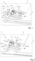
Figur 1 eine schematische Darstellung einer Ausführungsform eines erfindungsgemäßen stoßabsorbierenden Fahrzeugscheinwerfersystems in einer ersten Position, -
Figur 2 eine schematische Darstellung des erfindungsgemäßen stoßabsorbierenden Fahrzeugscheinwerfersystems gemäßFig. 1 in einer zweiten Position, -
Figur 3 eine schematische Darstellung des erfindungsgemäßen stoßabsorbierenden Fahrzeugscheinwerfersystems gemäßFig. 1 und Fig. 2 in einer dritten Position, und -
Figur 4 eine schematische Seitenansicht des erfindungsgemäßen stoßabsorbierenden Fahrzeugscheinwerfersystems gemäßFig. 1 bis 3 . - In den folgenden Figuren bezeichnen - sofern nicht anders angegeben - gleiche Bezugszeichen gleiche Merkmale.
-
Fig. 1 zeigt eine schematische Darstellung einer Ausführungsform eines erfindungsgemäßen stoßabsorbierenden Fahrzeugscheinwerfersystems 1 in einer ersten Position. Das stoßabsorbierende Fahrzeugscheinwerfersystem 1 umfasst zumindest ein mit einem Fahrzeug fest verbindbares Fahrzeugrahmenelement 2 sowie ein an dem Fahrzeugrahmenelement 2 verschiebbar gehaltenes Fahrzeugscheinwerfergehäuse 3 mit zumindest einem mit dem Fahrzeugscheinwerfergehäuse 3 verbundenen Zapfen 4, welcher vorzugsweise fest mit dem Fahrzeugscheinwerfergehäuse 3 verbunden ist. Das Fahrzeugrahmenelement 2 weist zumindest eine Führung 2a zur Aufnahme und linearen Führung des Zapfens 4 auf, wobei der Zapfen 4 mit der Führung 2a in Eingriff steht, sodass das Fahrzeugscheinwerfergehäuse 3 durch Verschiebung des Zapfens 4 entlang der Führung 2a geführt und dadurch in Bezug auf das Fahrzeugrahmenelement 2 verschiebbar ist. - Weiters weist das stoßabsorbierende Fahrzeugscheinwerfersystem 1 zumindest ein mit einem Stoßfänger (in den Figuren nicht gezeigt) eines Fahrzeuges mechanisch verbindbares Auslöseelement 5, und zumindest eine mit dem Fahrzeugrahmenelement 2 fest verbundene Auslösemechanik 6 auf. Die Auslösemechanik 6 ist dazu eingerichtet, das Auslöseelement 5 sowie den Zapfen 4 aufzunehmen und zumindest in Abhängigkeit von der Position des Auslöseelements 5 zwischen einem den Zapfen 4 blockierenden Zustand S1 (siehe
Fig. 1 ) und einem den Zapfen 4 freigebenden Zustand S2 (sieheFig. 3 ) zu wechseln. In dem den Zapfen 4 freigebenden Zustand S2 ist das Fahrzeugscheinwerfergehäuse 3 mitsamt dem Zapfen 4 in Bezug auf das Fahrzeugrahmenelement 2 verschiebbar, und zwar vorzugsweise entgegen der Hauptfahrrichtung des Fahrzeuges, sodass ein das Fahrzeugscheinwerfergehäuse 3 umfassender Scheinwerfer im Falle einer Kollision mit einem Fußgänger in das Fahrzeug hinein geschoben werden kann. - In
Fig. 1 ist erkennbar, dass die Auslösemechanik 6 einen in der Auslösemechanik 6 drehbar gelagerten Dreharm 6a umfasst. Der Dreharm 6a weist einen Eingriffsbereich 6a' zur Aufnahme des Zapfens 4 auf, wobei der Dreharm 6a dazu eingerichtet ist, zwischen zwei Positionen verdreht zu werden, nämlich zwischen einer Halteposition D1, in der der Dreharm 6a einer Bewegung eines im Eingriffsbereichs 6a' aufgenommenen Zapfens 4 entlang der Führung 2a entgegen wirkt, und einer Freigabeposition D2 (sieheFig. 3 ), in der der Dreharm 6a die Bewegung des Zapfens 4 entlang der Führung 2a freigibt. Weiters weist die Auslösemechanik 6 ein Verriegelungselement 6b auf, welches linear verschiebbar in der Auslösemechanik 6 gehalten ist, wobei das Verriegelungselement 6b dazu eingerichtet ist, in den Dreharm 6a in der Blockierposition D1 einzugreifen, und diesen in Abhängigkeit von der Position des Auslöseelements 5 in dieser Blockierposition D1 zu verriegeln oder einen Wechsel in die Freigabeposition D2 freizugeben. Hierzu ist vorgesehen, dass das Verriegelungselement 6b zwischen einer Verriegelungsposition V1 zum Blockieren des Dreharmes 6a und einer Entriegelungsposition V2 (sieheFig. 3 ) zum Freigeben des Wechsel des Dreharmes 6a in die Freigabeposition D2 verschiebbar ist. Es ist ein erstes Federelement 6c vorgesehen, das auf das Verriegelungselement 6b eine dieses in die Verriegelungsposition V1 drückende Federkraft FF1 ausübt. Das Verriegelungselement 6b ist mit dem Auslöseelement 5 dergestalt mechanisch gekoppelt, dass in einer Ausgangsposition P1 des Auslöseelements 5 das Verriegelungselement 6b mit Hilfe des ersten Federelements 6c in der Verriegelungsposition V1 gehalten ist, und dass in Folge einer Verschiebung der Position des Auslöseelements 5 in eine Auslöseposition P2 (sieheFig. 3 ) das Verriegelungselement 6b entgegen der Federkraft FF1 in die Entriegelungsposition V2 verschoben ist, sodass eine Drehung des Dreharms 6a von der Halteposition D1 hin zur Freigabeposition D2 ermöglicht wird, und die Auslösemechanik 6 somit in den freigebenden Zustand S2 wechselt. - In
Fig. 4 , die eine seitliche Ansicht des stoßabsorbierenden Fahrzeugscheinwerfersystems 1 zeigt, ist erkennbar, dass ein zweites Federelement 7 vorgesehen ist, das mit dem Fahrzeugrahmenelement 2 und mit dem Fahrzeugscheinwerfergehäuse 3 verbunden ist. Das zweite Federelement 7 ist dazu eingerichtet, auf das Fahrzeugscheinwerfergehäuse 3 eine rückstellende Federkraft FF2 auszuüben, sodass der Zapfen 4 in Richtung des Dreharmes 6a gedrückt wird. Wenn der Zapfen 4 im Dreharm 6a gehalten wird, befindet sich das Fahrzeugscheinwerfergehäuse 3 daher in einer Ruheposition; im Falle eines Stoßes des Auslöseelements 5 wird der Dreharm 6a freigegeben und das Fahrzeugscheinwerfergehäuse 3 kann mitsamt dem Zapfen 4 typischerweise entgegen der Hauptabstrahlrichtung des Scheinwerfers verschoben werden. Die Feder 7 nimmt dabei auch Stoßenergie auf, die beispielsweise von einem Fußgänger im Falle einer Kollision auf das Fahrzeug, insbesondere auf den Scheinwerfer, übertragen wird. - Mit Blick auf
Fig. 1 sei nun erwähnt, dass die Auslösemechanik 6 ein drittes Federelement 6d aufweisen kann, das dergestalt angeordnet ist, dass auf den Dreharm 6a eine Kraft FF3 ausgeübt wird, die den Dreharm 6a in Richtung der Halteposition D1 drückt. Dadurch kann eine automatische Rückstellung des Dreharms 6a erfolgen. - Weiters kann vorgesehen sein, dass die Auslösemechanik 6 ein verschiebbares Halteelement 6e sowie ein viertes Federelement 6f aufweist. Das Halteelement 6e ist mit Hilfe des Federelements 6f dazu eingerichtet, einen Wechsel des Dreharms 6a von der Freigabeposition D2 in die Blockierposition D1 zu behindern, indem auf einen in der Freigabeposition D2 befindlichen Dreharm 6a eine Federkraft FF4 ausgeübt wird, die der Federkraft FF3 des dritten Federelements 6d entgegen wirkt und diese übersteigt, sodass erst durch Hinzukommen einer durch den Zapfen 4 ausgeübten Rückstellkraft FF2 des zweiten Federelements 7 eine Rückstellung des Dreharms 6a durch Verschiebung des Halteelements 6e entgegen der Federkraft FF4 des vierten Federelements 6f freigegeben wird. Das Auslöseelement 5 kann als Vorsprung, insbesondere als Zapfen, ausgebildet sein. Es kann vorgesehen sein, dass das Verriegelungselement 6b einen Haken 6b' zum Eingriff in den Dreharm 6a aufweist.
- Mit Blick auf
Fig. 1 bis 3 sei nun ein Auslösevorgang des stoßabsorbierenden Fahrzeugscheinwerfersystems 1 erklärt, wobei das stoßabsorbierende Fahrzeugscheinwerfersystem 1 selbstheilend ausgeführt ist. Wird ausgehend vonFig. 1 ein Stoß auf eine mit dem Auslöseelement 5 verbundene Stoßstange bzw. einen Stoßfänger durchgeführt, dann kann sich das Auslöseelement 5 hin zu der Auslösemechanik 6 verschieben. Durch die eindringende geschrägte Fläche 5' des Auslöseelements 5 (rein schematische Darstellung) wird das Verriegelungselement 6b entgegen der Federkraft FF1 nach links geschoben (sieheFig. 2 in einer Mittelposition P12 undFig. 3 in der Position P2), wodurch der Haken 6b' nicht mehr in den Dreharm 6a eingreift. Wirkt der Stoß nun auch auf das Fahrzeugscheinwerfergehäuse 3, so kann dieses mitsamt dem Zapfen 4 entlang der Führung 2a in Richtung der Fahrzeugmitte verschoben werden. Die durch den Zapfen 4 ausgeübte Kraft drückt den Dreharm 6a entgegen der Federkraft FF3 in die Position D3 (sieheFig. 3 ), in der der Zapfen 4 freigegeben wird, sodass dieser entlang der Führung 2a entgegen der Federkraft FF2 in Richtung der Fahrzeugmitte bis zum Erreichen eines maximalen Hubes gleiten kann. Die Führung 2a und der Zapfen 4 können dergestalt ausgelegt sein, dass der maximale Hub des Fahrzeugscheinwerfergehäuses 3 entlang der Führung 2a zwischen 3cm und 10cm, insbesondere zwischen 5cm und 7cm, beträgt. Die Führung 2a im Fahrzeugrahmenelement 2 kann z.B. als Nut oder Langloch ausgebildet sein. Anders ausgedrückt ist das Verriegelungselement 6b dergestalt mit dem Auslöseelement 5 mechanisch gekoppelt, dass durch Eindringen des Auslöseelements 5 in das Verriegelungselement 6b das Verriegelungselement 6b entgegen der Kraft des ersten Federelements 6c in die Entriegelungsposition V2 gedrückt wird.Fig. 2 zeigt die Auslösemechanik 6 in einer Zwischenposition, in der der Zapfen 4 noch im Dreharm 6a gehalten wird, der Dreharm 6a in einer Position P12 allerdings nicht mehr durch das Verriegelungselement 6b verriegelt ist und daher sowohl in Richtung der Federkraft FF3 als auch entgegen dieser Kraft bewegt werden kann. Die Bewegungsrichtung hängt davon ab, ob auf das Scheinwerfergehäuse 3 noch eine äußere Kraft in Folge einer Kollision wirkt. Falls dies nicht zutrifft, so wird der Zapfen 4 in den Dreharm 6a gedrückt, sodass sich der Dreharm 6a mitsamt den Zapfen wieder in die Ausgangsposition D1 begibt. Das Auslöseelement 5 verlässt dann die Zwischenposition P12 und wandert wieder zurück in die Ausgangsposition P1. - Es kann vorgesehen sein, dass das Fahrzeugscheinwerfergehäuse 3 zumindest ein Lichtmodul einschließt, das zur Abgabe einer Lichtverteilung, insbesondere einer Abblendlichtverteilung und/oder einer Fernlichtverteilung eingerichtet ist.
- Weiters betrifft die Erfindung ein in den Figuren nicht gezeigtes Kraftfahrzeug, umfassend zumindest ein erfindungsgemäßes stoßabsorbierendes Fahrzeugscheinwerfersystem 1.
- Das Kraftfahrzeug kann zwei Frontscheinwerfereinheiten zur Erzeugung einer Abblendlichtverteilung sowie einer Fernlichtverteilung aufweisen, wobei das Kraftfahrzeug zwei erfindungsgemäße stoßabsorbierende Fahrzeugscheinwerfersysteme aufweisen kann, wobei die zwei Fahrzeugscheinwerfergehäuse 3 der zwei stoßabsorbierenden Fahrzeugscheinwerfersysteme die Fahrzeugscheinwerfergehäuse der beiden Frontscheinwerfereinheiten ausbilden.
- Weiters kann vorgesehen sein, dass das Kraftfahrzeug eine Stoßstange aufweist, wobei jedes Auslöseelement 5 mit der Stoßstange verbunden ist, sodass im Falle einer kollisionsbedingten Verschiebung der Stoßstange das Auslöseelement in Richtung des Fahrzeugscheinwerfers verschoben wird, und damit eine Verschiebung des Fahrzeugscheinwerfers entgegen der Hauptfahrrichtung des Fahrzeuges ermöglicht ist.
- Die Erfindung ist nicht auf die gezeigten Ausführungsformen beschränkt, sondern durch den gesamten Schutzumfang der Ansprüche definiert. Auch können einzelne Aspekte der Erfindung bzw. der Ausführungsformen aufgegriffen und miteinander kombiniert werden. Etwaige Bezugszeichen in den Ansprüchen sind beispielhaft und dienen nur der einfacheren Lesbarkeit der Ansprüche, ohne diese einzuschränken.
Claims (13)
- Stoßabsorbierendes Fahrzeugscheinwerfersystem (1), aufweisend- zumindest ein mit einem Fahrzeug fest verbindbares Fahrzeugrahmenelement (2),- ein an dem Fahrzeugrahmenelement (2) verschiebbar gehaltenes Fahrzeugscheinwerfergehäuse (3) mit zumindest einem mit dem Fahrzeugscheinwerfergehäuse (3) verbundenen Zapfen (4), welcher vorzugsweise fest mit dem Fahrzeugscheinwerfergehäuse (3) verbunden ist, wobei das Fahrzeugrahmenelement (2) zumindest eine Führung (2a) zur Aufnahme und linearen Führung des Zapfens (4) aufweist, wobei der Zapfen (4) mit der Führung (2a) in Eingriff steht, sodass das Fahrzeugscheinwerfergehäuse (3) durch Verschiebung des Zapfens (4) entlang der Führung (2a) geführt und dadurch in Bezug auf das Fahrzeugrahmenelement (2) verschiebbar ist,- zumindest ein mit einem Stoßfänger eines Fahrzeuges mechanisch verbindbares Auslöseelement (5), und- zumindest eine mit dem Fahrzeugrahmenelement (2) fest verbundene Auslösemechanik (6), welche dazu eingerichtet ist, das Auslöseelement (5) sowie den Zapfen (4) aufzunehmen und zumindest in Abhängigkeit von der Position des Auslöseelements (5) zwischen einem den Zapfen (4) blockierenden Zustand (S1) und einem den Zapfen (4) freigebenden Zustand (S2) zu wechseln, wobei im den Zapfen (4) freigebenden Zustand (S2) das Fahrzeugscheinwerfergehäuse (3) mitsamt dem Zapfen (4) in Bezug auf das Fahrzeugrahmenelement (2) verschiebbar ist,dadurch gekennzeichnet, dass
die Auslösemechanik (6) Folgendes umfasst:*einen in der Auslösemechanik (6) drehbar gelagerten Dreharm (6a), welcher Dreharm (6a) einen Eingriffsbereich (6a') zur Aufnahme des Zapfens (4) aufweist, wobei der Dreharm (6a) dazu eingerichtet ist, zwischen zwei Positionen verdreht zu werden, nämlich zwischen einer Halteposition (D1), in der der Dreharm (6a) einer Bewegung eines im Eingriffsbereichs (6a') aufgenommenen Zapfens (4) entlang der Führung (2a) entgegen wirkt, und einer Freigabeposition (D2), in der der Dreharm (6a) die Bewegung des Zapfens (4) entlang der Führung (2a) freigibt,*ein Verriegelungselement (6b), welches linear verschiebbar in der Auslösemechanik (6) gehalten ist, wobei das Verriegelungselement (6b) dazu eingerichtet ist, in den Dreharm (6a) in der Blockierposition (D1) einzugreifen, und diesen in Abhängigkeit von der Position des Auslöseelements (5) in dieser Blockierposition (D1) zu verriegeln oder einen Wechsel in die Freigabeposition (D2) freizugeben, indem das Verriegelungselement (6b) zwischen einer Verriegelungsposition (V1) zum Blockieren des Dreharmes (6a) und einer Entriegelungsposition (V2) zum Freigeben des Wechsel des Dreharmes (6a) in die Freigabeposition (D2) verschiebbar ist, wobei ein erstes Federelement (6c) vorgesehen ist, das auf das Verriegelungselement (6b) eine dieses in die Verriegelungsposition (V1) drückende Federkraft (FF1) ausübt, wobei das Verriegelungselement (6b) mit dem Auslöseelement (5) dergestalt mechanisch gekoppelt ist, dass in einer Ausgangsposition (P1) des Auslöseelements (5) das Verriegelungselement (6b) mit Hilfe des ersten Federelements (6c) in der Verriegelungsposition (V1) gehalten ist, und dass in Folge einer Verschiebung der Position des Auslöseelements (5) in eine Auslöseposition (P2) das Verriegelungselement (6b) entgegen der Federkraft (FF1) in die Entriegelungsposition (V2) verschoben ist, sodass eine Drehung des Dreharms (6a) von der Halteposition (D1) hin zur Freigabeposition (D2) ermöglicht wird, und die Auslösemechanik (6) somit in den freigebenden Zustand (S2) wechselt. - Stoßabsorbierendes Fahrzeugscheinwerfersystem (1) nach Anspruch 1, wobei ein zweites Federelement (7) vorgesehen ist, das mit dem Fahrzeugrahmenelement (2) und mit dem Fahrzeugscheinwerfergehäuse (3) verbunden ist, wobei das Federelement (7) dazu eingerichtet ist, auf das Fahrzeugscheinwerfergehäuse (3) eine rückstellende Federkraft (FF2) auszuüben, sodass der Zapfen (4) in Richtung des Dreharmes (6a) gedrückt wird.
- Stoßabsorbierendes Fahrzeugscheinwerfersystem (1) nach einem der vorhergehenden Ansprüche, wobei die Auslösemechanik (6) ein drittes Federelement (6d) aufweist, das dergestalt angeordnet ist, dass auf den Dreharm (6a) eine Kraft (FF3) ausgeübt wird, die den Dreharm (6a) in Richtung der Halteposition (D1) drückt.
- Stoßabsorbierendes Fahrzeugscheinwerfersystem (1) nach einem der vorhergehenden Ansprüche, wobei die Auslösemechanik (6) ein verschiebbares Halteelement (6e) sowie ein viertes Federelement (6f) aufweist, wobei das Halteelement (6e) mit Hilfe des Federelements (6f) dazu eingerichtet ist, einen Wechsel des Dreharms (6a) von der Freigabeposition (D2) in die Blockierposition (D1) zu behindern, indem auf einen in der Freigabeposition (D2) befindlichen Dreharm (6a) eine Federkraft (FF4) ausgeübt wird, die der Federkraft (FF3) des dritten Federelements (6d) entgegen wirkt und diese übersteigt, sodass erst durch Hinzukommen einer durch den Zapfen (4) ausgeübten Rückstellkraft (FF2) des zweiten Federelements (7) eine Rückstellung des Dreharms (6a) durch Verschiebung des Halteelements (6e) entgegen der Federkraft (FF4) des vierten Federelements (6f) freigegeben wird.
- Stoßabsorbierendes Fahrzeugscheinwerfersystem (1) nach einem der vorhergehenden Ansprüche, wobei das Auslöseelement (5) als Vorsprung, insbesondere als Zapfen, ausgebildet ist.
- Stoßabsorbierendes Fahrzeugscheinwerfersystem (1) nach einem der vorhergehenden Ansprüche, wobei das Verriegelungselement (6b) einen Haken (6b') zum Eingriff in den Dreharm (6a) aufweist.
- Stoßabsorbierendes Fahrzeugscheinwerfersystem (1) nach einem der vorhergehenden Ansprüche, wobei die Führung (2a) im Fahrzeugrahmenelement (2) als Nut oder Langloch ausgebildet ist.
- Stoßabsorbierendes Fahrzeugscheinwerfersystem (1) nach einem der vorhergehenden Ansprüche, wobei das Verriegelungselement (6b) dergestalt mit dem Auslöseelement (5) mechanisch gekoppelt ist, dass durch Eindringen des Auslöseelements (5) in das Verriegelungselement (6b) das Verriegelungselement (6b) entgegen der Kraft des ersten Federelements (6c) in die Entriegelungsposition (V2) gedrückt wird.
- Stoßabsorbierendes Fahrzeugscheinwerfersystem (1) nach einem der vorhergehenden Ansprüche, wobei das Fahrzeugscheinwerfergehäuse (3) zumindest ein Lichtmodul einschließt, das zur Abgabe einer Lichtverteilung eingerichtet ist.
- Stoßabsorbierendes Fahrzeugscheinwerfersystem (1) nach einem der vorhergehenden Ansprüche, wobei die Führung (2a) und der Zapfen (4) dergestalt ausgelegt sind, dass der maximale Hub des Fahrzeugscheinwerfergehäuses (3) entlang der Führung (2a) zwischen 3cm und 10cm, insbesondere zwischen 5cm und 7cm, beträgt.
- Kraftfahrzeug umfassend zumindest ein stoßabsorbierendes Fahrzeugscheinwerfersystem (1) nach einem der vorhergehenden Ansprüche.
- Kraftfahrzeug nach Anspruch 11, wobei das Kraftfahrzeug zwei Frontscheinwerfereinheiten zur Erzeugung einer Abblendlichtverteilung sowie einer Fernlichtverteilung aufweist, wobei das Kraftfahrzeug zwei stoßabsorbierende Fahrzeugscheinwerfersysteme nach einem der Ansprüchen 1 bis 10 aufweist, wobei die zwei Fahrzeugscheinwerfergehäuse (3) der zwei stoßabsorbierenden Fahrzeugscheinwerfersysteme die Fahrzeugscheinwerfergehäuse der beiden Frontscheinwerfereinheiten ausbilden.
- Kraftfahrzeug nach Anspruch 12, wobei das Kraftfahrzeug eine Stoßstange aufweist, wobei jedes Auslöseelement (5) mit der Stoßstange verbunden ist, sodass im Falle einer kollisionsbedingten Verschiebung der Stoßstange das Auslöseelement in Richtung des Fahrzeugscheinwerfers verschoben wird, und damit eine Verschiebung des Fahrzeugscheinwerfers entgegen der Hauptfahrrichtung des Fahrzeuges ermöglicht ist.
Priority Applications (5)
| Application Number | Priority Date | Filing Date | Title |
|---|---|---|---|
| EP21215092.4A EP4197858B1 (de) | 2021-12-16 | 2021-12-16 | Stossabsorbierendes fahrzeugscheinwerfersystem |
| JP2022194104A JP7407265B2 (ja) | 2021-12-16 | 2022-12-05 | 衝撃吸収式の車両投光器システム |
| US18/081,598 US11745640B2 (en) | 2021-12-16 | 2022-12-14 | Impact-absorbing vehicle headlamp system |
| CN202211619865.7A CN116265288B (zh) | 2021-12-16 | 2022-12-16 | 减震的车辆前照灯系统 |
| KR1020220176429A KR102804955B1 (ko) | 2021-12-16 | 2022-12-16 | 충격 흡수식 차량 헤드라이트 시스템 |
Applications Claiming Priority (1)
| Application Number | Priority Date | Filing Date | Title |
|---|---|---|---|
| EP21215092.4A EP4197858B1 (de) | 2021-12-16 | 2021-12-16 | Stossabsorbierendes fahrzeugscheinwerfersystem |
Publications (2)
| Publication Number | Publication Date |
|---|---|
| EP4197858A1 true EP4197858A1 (de) | 2023-06-21 |
| EP4197858B1 EP4197858B1 (de) | 2024-07-03 |
Family
ID=78918701
Family Applications (1)
| Application Number | Title | Priority Date | Filing Date |
|---|---|---|---|
| EP21215092.4A Active EP4197858B1 (de) | 2021-12-16 | 2021-12-16 | Stossabsorbierendes fahrzeugscheinwerfersystem |
Country Status (5)
| Country | Link |
|---|---|
| US (1) | US11745640B2 (de) |
| EP (1) | EP4197858B1 (de) |
| JP (1) | JP7407265B2 (de) |
| KR (1) | KR102804955B1 (de) |
| CN (1) | CN116265288B (de) |
Families Citing this family (1)
| Publication number | Priority date | Publication date | Assignee | Title |
|---|---|---|---|---|
| EP4296120B1 (de) * | 2022-06-21 | 2025-01-08 | ZKW Group GmbH | Stossabsorbierendes fahrzeugscheinwerfersystem |
Citations (7)
| Publication number | Priority date | Publication date | Assignee | Title |
|---|---|---|---|---|
| JPH03208738A (ja) * | 1990-01-12 | 1991-09-11 | Nissan Motor Co Ltd | 車両用ヘッドランプの取付構造 |
| JPH0930321A (ja) * | 1995-07-17 | 1997-02-04 | Honda Motor Co Ltd | 車両用灯体の取付構造 |
| JPH11165581A (ja) * | 1997-12-01 | 1999-06-22 | Mitsubishi Motors Corp | 車両用灯具の取付構造 |
| EP1332915B1 (de) | 2002-01-30 | 2011-12-28 | Volvo Car Corporation | Scheinwerferanordnung mit Fussgängerschutzeinrichtung |
| FR2983142A1 (fr) * | 2011-11-24 | 2013-05-31 | Renault Sa | Ensemble d'un projecteur et son dispositif de montage limitant les reparations de l'aile adjacente lors d'un choc et vehicule correspondant |
| EP3501894A1 (de) * | 2017-12-19 | 2019-06-26 | Ningbo Geely Automobile Research & Development Co., Ltd. | Vorrichtung zum aufhängen einer lampe in einem fahrzeug |
| JP2021079770A (ja) * | 2019-11-15 | 2021-05-27 | スズキ株式会社 | 車両用ランプ取付構造 |
Family Cites Families (15)
| Publication number | Priority date | Publication date | Assignee | Title |
|---|---|---|---|---|
| US4614015A (en) * | 1985-10-02 | 1986-09-30 | American Sterilizer Company | Device for retaining/ejecting a lamp from a socket and frame |
| DE19926346A1 (de) * | 1999-06-09 | 2000-12-14 | Hella Kg Hueck & Co | Scheinwerfer |
| JP4043818B2 (ja) * | 2002-03-22 | 2008-02-06 | 株式会社小糸製作所 | 車輌用前照灯 |
| FR2844757B1 (fr) * | 2002-09-20 | 2005-10-07 | Valeo Vision | Projecteur de vehicule automobile comportant des moyens perfectionnes de liaison au chassis du vehicule |
| DE10258629B4 (de) * | 2002-12-16 | 2006-07-27 | Daimlerchrysler Ag | Fahrzeug |
| KR20060081183A (ko) * | 2005-01-07 | 2006-07-12 | 현대자동차주식회사 | 차량의 헤드램프 체결구조 |
| KR100696041B1 (ko) * | 2005-08-16 | 2007-03-16 | 현대모비스 주식회사 | 차량 전조등의 충격 흡수 장치 |
| KR20070045598A (ko) * | 2005-10-27 | 2007-05-02 | 현대자동차주식회사 | 자동차의 헤드램프 마운팅 클립 |
| FR2895063A1 (fr) * | 2005-12-20 | 2007-06-22 | Valeo Vision Sa | Porte lampe de projecteur equipe de griffes orientees tangentiellement par rapport a la paroi du porte lampe |
| DE102011115797A1 (de) * | 2011-10-11 | 2013-04-11 | Gm Global Technology Operations, Llc | Scheinwerferbaueinheit eines Fahrzeugs mit Scheinwerferbefestigungsvorrichtung |
| DE102013007896A1 (de) * | 2013-05-07 | 2014-11-13 | Daimler Ag | Abstützanordnung eines Stoßfängers an einem Frontmodul eines Kraftwagens |
| DE102014205412A1 (de) * | 2014-03-24 | 2015-09-24 | Bayerische Motoren Werke Aktiengesellschaft | Anordnung zum Absorbieren von Bewegungsenergie |
| US10272819B2 (en) * | 2017-01-04 | 2019-04-30 | Ford Global Technologies, Llc | Loose layered build components and vehicle front end assembly strategy |
| EP3616993B1 (de) * | 2018-08-27 | 2023-05-24 | ZKW Group GmbH | Kraftfahrzeugscheinwerfer mit einer einstellvorrichtung |
| US11028989B2 (en) * | 2019-11-13 | 2021-06-08 | James M. Aparo | Vehicle headlight device having an ejectable and replaceable lightbulb assembly |
-
2021
- 2021-12-16 EP EP21215092.4A patent/EP4197858B1/de active Active
-
2022
- 2022-12-05 JP JP2022194104A patent/JP7407265B2/ja active Active
- 2022-12-14 US US18/081,598 patent/US11745640B2/en active Active
- 2022-12-16 KR KR1020220176429A patent/KR102804955B1/ko active Active
- 2022-12-16 CN CN202211619865.7A patent/CN116265288B/zh active Active
Patent Citations (7)
| Publication number | Priority date | Publication date | Assignee | Title |
|---|---|---|---|---|
| JPH03208738A (ja) * | 1990-01-12 | 1991-09-11 | Nissan Motor Co Ltd | 車両用ヘッドランプの取付構造 |
| JPH0930321A (ja) * | 1995-07-17 | 1997-02-04 | Honda Motor Co Ltd | 車両用灯体の取付構造 |
| JPH11165581A (ja) * | 1997-12-01 | 1999-06-22 | Mitsubishi Motors Corp | 車両用灯具の取付構造 |
| EP1332915B1 (de) | 2002-01-30 | 2011-12-28 | Volvo Car Corporation | Scheinwerferanordnung mit Fussgängerschutzeinrichtung |
| FR2983142A1 (fr) * | 2011-11-24 | 2013-05-31 | Renault Sa | Ensemble d'un projecteur et son dispositif de montage limitant les reparations de l'aile adjacente lors d'un choc et vehicule correspondant |
| EP3501894A1 (de) * | 2017-12-19 | 2019-06-26 | Ningbo Geely Automobile Research & Development Co., Ltd. | Vorrichtung zum aufhängen einer lampe in einem fahrzeug |
| JP2021079770A (ja) * | 2019-11-15 | 2021-05-27 | スズキ株式会社 | 車両用ランプ取付構造 |
Also Published As
| Publication number | Publication date |
|---|---|
| CN116265288A (zh) | 2023-06-20 |
| US20230191983A1 (en) | 2023-06-22 |
| KR20230091819A (ko) | 2023-06-23 |
| US11745640B2 (en) | 2023-09-05 |
| JP7407265B2 (ja) | 2023-12-28 |
| CN116265288B (zh) | 2026-02-13 |
| EP4197858B1 (de) | 2024-07-03 |
| JP2023089948A (ja) | 2023-06-28 |
| KR102804955B1 (ko) | 2025-05-09 |
Similar Documents
| Publication | Publication Date | Title |
|---|---|---|
| EP3157800B1 (de) | Lenksäule für ein kraftfahrzeug | |
| EP3501942B1 (de) | Lenksäulenbaugruppe | |
| DE102004006873B3 (de) | Kraftfahrzeugsitz | |
| DE2713973A1 (de) | Feststellvorrichtung fuer gleitschienenfuehrungen | |
| EP1038617B1 (de) | Werkzeughalter und Werkzeugmaschine | |
| DE102021116952A1 (de) | Parksperre | |
| EP1275541A1 (de) | Modul, insbesondere Schiebedachmodul für ein Fahrzeug | |
| DE102013012832A1 (de) | Verstelleinrichtung für ein Schloss einer Frontklappe eines Kraftfahrzeugs und zugehöriges Kraftfahrzeug | |
| EP4197858B1 (de) | Stossabsorbierendes fahrzeugscheinwerfersystem | |
| DE102021124656A1 (de) | Fahrzeugparkverriegelungsmechanismus | |
| EP1541425A1 (de) | Haltevorrichtung für eine Fahrzeugsicherheitsvorrichtung | |
| DE102015204705A1 (de) | Verbreiterbarer Tisch | |
| EP3643565B1 (de) | Vorrichtung, system und verfahren zum sichern einer last in einem fahrzeug | |
| EP4296120B1 (de) | Stossabsorbierendes fahrzeugscheinwerfersystem | |
| WO2004101188A1 (de) | Werkzeugaufnahmevorrichtung | |
| DE10229635C1 (de) | Überrollschutzsystem für Kraftfahrzeuge | |
| DE2440361B2 (de) | Mechanische verriegelung von beweglichen teilen | |
| DE10044927C1 (de) | Überrollschutzsystem für Kraftfahrzeuge | |
| DE8000783U1 (de) | Auslenkbare Halterung | |
| EP0645295B1 (de) | Auffahrbarer Weichenantrieb | |
| DE102005028962B4 (de) | Überrollschutzsystem mit Rasteinrichtung für ein Kraftfahrzeug | |
| DE102013102224A1 (de) | Verriegelungseinrichtung für eine Schienenführung eines Fahrzeugsitzes | |
| EP2139085A1 (de) | Gehäuse mit Verriegelungselement | |
| DE10327447B3 (de) | Vorrichtung zum Schutz von Personen bei einem Frontalaufprall auf ein Kraftfahrzeug | |
| EP3439939B1 (de) | Verriegelungseinrichtung an zwei relativ zu einander an einer führungsbahn gleitend beweglichen körpern |
Legal Events
| Date | Code | Title | Description |
|---|---|---|---|
| PUAI | Public reference made under article 153(3) epc to a published international application that has entered the european phase |
Free format text: ORIGINAL CODE: 0009012 |
|
| STAA | Information on the status of an ep patent application or granted ep patent |
Free format text: STATUS: THE APPLICATION HAS BEEN PUBLISHED |
|
| AK | Designated contracting states |
Kind code of ref document: A1 Designated state(s): AL AT BE BG CH CY CZ DE DK EE ES FI FR GB GR HR HU IE IS IT LI LT LU LV MC MK MT NL NO PL PT RO RS SE SI SK SM TR |
|
| STAA | Information on the status of an ep patent application or granted ep patent |
Free format text: STATUS: REQUEST FOR EXAMINATION WAS MADE |
|
| 17P | Request for examination filed |
Effective date: 20231201 |
|
| RBV | Designated contracting states (corrected) |
Designated state(s): AL AT BE BG CH CY CZ DE DK EE ES FI FR GB GR HR HU IE IS IT LI LT LU LV MC MK MT NL NO PL PT RO RS SE SI SK SM TR |
|
| GRAP | Despatch of communication of intention to grant a patent |
Free format text: ORIGINAL CODE: EPIDOSNIGR1 |
|
| STAA | Information on the status of an ep patent application or granted ep patent |
Free format text: STATUS: GRANT OF PATENT IS INTENDED |
|
| INTG | Intention to grant announced |
Effective date: 20240209 |
|
| GRAS | Grant fee paid |
Free format text: ORIGINAL CODE: EPIDOSNIGR3 |
|
| GRAA | (expected) grant |
Free format text: ORIGINAL CODE: 0009210 |
|
| STAA | Information on the status of an ep patent application or granted ep patent |
Free format text: STATUS: THE PATENT HAS BEEN GRANTED |
|
| AK | Designated contracting states |
Kind code of ref document: B1 Designated state(s): AL AT BE BG CH CY CZ DE DK EE ES FI FR GB GR HR HU IE IS IT LI LT LU LV MC MK MT NL NO PL PT RO RS SE SI SK SM TR |
|
| REG | Reference to a national code |
Ref country code: CH Ref legal event code: EP |
|
| REG | Reference to a national code |
Ref country code: DE Ref legal event code: R096 Ref document number: 502021004209 Country of ref document: DE |
|
| P01 | Opt-out of the competence of the unified patent court (upc) registered |
Free format text: CASE NUMBER: APP_51268/2024 Effective date: 20240911 |
|
| REG | Reference to a national code |
Ref country code: LT Ref legal event code: MG9D |
|
| REG | Reference to a national code |
Ref country code: NL Ref legal event code: MP Effective date: 20240703 |
|
| PG25 | Lapsed in a contracting state [announced via postgrant information from national office to epo] |
Ref country code: PT Free format text: LAPSE BECAUSE OF FAILURE TO SUBMIT A TRANSLATION OF THE DESCRIPTION OR TO PAY THE FEE WITHIN THE PRESCRIBED TIME-LIMIT Effective date: 20241104 |
|
| PG25 | Lapsed in a contracting state [announced via postgrant information from national office to epo] |
Ref country code: NL Free format text: LAPSE BECAUSE OF FAILURE TO SUBMIT A TRANSLATION OF THE DESCRIPTION OR TO PAY THE FEE WITHIN THE PRESCRIBED TIME-LIMIT Effective date: 20240703 |
|
| PG25 | Lapsed in a contracting state [announced via postgrant information from national office to epo] |
Ref country code: PT Free format text: LAPSE BECAUSE OF FAILURE TO SUBMIT A TRANSLATION OF THE DESCRIPTION OR TO PAY THE FEE WITHIN THE PRESCRIBED TIME-LIMIT Effective date: 20241104 Ref country code: NL Free format text: LAPSE BECAUSE OF FAILURE TO SUBMIT A TRANSLATION OF THE DESCRIPTION OR TO PAY THE FEE WITHIN THE PRESCRIBED TIME-LIMIT Effective date: 20240703 |
|
| PG25 | Lapsed in a contracting state [announced via postgrant information from national office to epo] |
Ref country code: NO Free format text: LAPSE BECAUSE OF FAILURE TO SUBMIT A TRANSLATION OF THE DESCRIPTION OR TO PAY THE FEE WITHIN THE PRESCRIBED TIME-LIMIT Effective date: 20241003 |
|
| PG25 | Lapsed in a contracting state [announced via postgrant information from national office to epo] |
Ref country code: FI Free format text: LAPSE BECAUSE OF FAILURE TO SUBMIT A TRANSLATION OF THE DESCRIPTION OR TO PAY THE FEE WITHIN THE PRESCRIBED TIME-LIMIT Effective date: 20240703 Ref country code: GR Free format text: LAPSE BECAUSE OF FAILURE TO SUBMIT A TRANSLATION OF THE DESCRIPTION OR TO PAY THE FEE WITHIN THE PRESCRIBED TIME-LIMIT Effective date: 20241004 Ref country code: PL Free format text: LAPSE BECAUSE OF FAILURE TO SUBMIT A TRANSLATION OF THE DESCRIPTION OR TO PAY THE FEE WITHIN THE PRESCRIBED TIME-LIMIT Effective date: 20240703 |
|
| PG25 | Lapsed in a contracting state [announced via postgrant information from national office to epo] |
Ref country code: BG Free format text: LAPSE BECAUSE OF FAILURE TO SUBMIT A TRANSLATION OF THE DESCRIPTION OR TO PAY THE FEE WITHIN THE PRESCRIBED TIME-LIMIT Effective date: 20240703 |
|
| PG25 | Lapsed in a contracting state [announced via postgrant information from national office to epo] |
Ref country code: LV Free format text: LAPSE BECAUSE OF FAILURE TO SUBMIT A TRANSLATION OF THE DESCRIPTION OR TO PAY THE FEE WITHIN THE PRESCRIBED TIME-LIMIT Effective date: 20240703 |
|
| PG25 | Lapsed in a contracting state [announced via postgrant information from national office to epo] |
Ref country code: IS Free format text: LAPSE BECAUSE OF FAILURE TO SUBMIT A TRANSLATION OF THE DESCRIPTION OR TO PAY THE FEE WITHIN THE PRESCRIBED TIME-LIMIT Effective date: 20241103 |
|
| PG25 | Lapsed in a contracting state [announced via postgrant information from national office to epo] |
Ref country code: HR Free format text: LAPSE BECAUSE OF FAILURE TO SUBMIT A TRANSLATION OF THE DESCRIPTION OR TO PAY THE FEE WITHIN THE PRESCRIBED TIME-LIMIT Effective date: 20240703 Ref country code: CZ Free format text: LAPSE BECAUSE OF FAILURE TO SUBMIT A TRANSLATION OF THE DESCRIPTION OR TO PAY THE FEE WITHIN THE PRESCRIBED TIME-LIMIT Effective date: 20240703 |
|
| PG25 | Lapsed in a contracting state [announced via postgrant information from national office to epo] |
Ref country code: RS Free format text: LAPSE BECAUSE OF FAILURE TO SUBMIT A TRANSLATION OF THE DESCRIPTION OR TO PAY THE FEE WITHIN THE PRESCRIBED TIME-LIMIT Effective date: 20241003 Ref country code: ES Free format text: LAPSE BECAUSE OF FAILURE TO SUBMIT A TRANSLATION OF THE DESCRIPTION OR TO PAY THE FEE WITHIN THE PRESCRIBED TIME-LIMIT Effective date: 20240703 |
|
| PG25 | Lapsed in a contracting state [announced via postgrant information from national office to epo] |
Ref country code: RS Free format text: LAPSE BECAUSE OF FAILURE TO SUBMIT A TRANSLATION OF THE DESCRIPTION OR TO PAY THE FEE WITHIN THE PRESCRIBED TIME-LIMIT Effective date: 20241003 Ref country code: PL Free format text: LAPSE BECAUSE OF FAILURE TO SUBMIT A TRANSLATION OF THE DESCRIPTION OR TO PAY THE FEE WITHIN THE PRESCRIBED TIME-LIMIT Effective date: 20240703 Ref country code: NO Free format text: LAPSE BECAUSE OF FAILURE TO SUBMIT A TRANSLATION OF THE DESCRIPTION OR TO PAY THE FEE WITHIN THE PRESCRIBED TIME-LIMIT Effective date: 20241003 Ref country code: LV Free format text: LAPSE BECAUSE OF FAILURE TO SUBMIT A TRANSLATION OF THE DESCRIPTION OR TO PAY THE FEE WITHIN THE PRESCRIBED TIME-LIMIT Effective date: 20240703 Ref country code: IS Free format text: LAPSE BECAUSE OF FAILURE TO SUBMIT A TRANSLATION OF THE DESCRIPTION OR TO PAY THE FEE WITHIN THE PRESCRIBED TIME-LIMIT Effective date: 20241103 Ref country code: HR Free format text: LAPSE BECAUSE OF FAILURE TO SUBMIT A TRANSLATION OF THE DESCRIPTION OR TO PAY THE FEE WITHIN THE PRESCRIBED TIME-LIMIT Effective date: 20240703 Ref country code: GR Free format text: LAPSE BECAUSE OF FAILURE TO SUBMIT A TRANSLATION OF THE DESCRIPTION OR TO PAY THE FEE WITHIN THE PRESCRIBED TIME-LIMIT Effective date: 20241004 Ref country code: FI Free format text: LAPSE BECAUSE OF FAILURE TO SUBMIT A TRANSLATION OF THE DESCRIPTION OR TO PAY THE FEE WITHIN THE PRESCRIBED TIME-LIMIT Effective date: 20240703 Ref country code: ES Free format text: LAPSE BECAUSE OF FAILURE TO SUBMIT A TRANSLATION OF THE DESCRIPTION OR TO PAY THE FEE WITHIN THE PRESCRIBED TIME-LIMIT Effective date: 20240703 Ref country code: CZ Free format text: LAPSE BECAUSE OF FAILURE TO SUBMIT A TRANSLATION OF THE DESCRIPTION OR TO PAY THE FEE WITHIN THE PRESCRIBED TIME-LIMIT Effective date: 20240703 Ref country code: BG Free format text: LAPSE BECAUSE OF FAILURE TO SUBMIT A TRANSLATION OF THE DESCRIPTION OR TO PAY THE FEE WITHIN THE PRESCRIBED TIME-LIMIT Effective date: 20240703 |
|
| REG | Reference to a national code |
Ref country code: DE Ref legal event code: R097 Ref document number: 502021004209 Country of ref document: DE |
|
| PG25 | Lapsed in a contracting state [announced via postgrant information from national office to epo] |
Ref country code: RO Free format text: LAPSE BECAUSE OF FAILURE TO SUBMIT A TRANSLATION OF THE DESCRIPTION OR TO PAY THE FEE WITHIN THE PRESCRIBED TIME-LIMIT Effective date: 20240703 Ref country code: DK Free format text: LAPSE BECAUSE OF FAILURE TO SUBMIT A TRANSLATION OF THE DESCRIPTION OR TO PAY THE FEE WITHIN THE PRESCRIBED TIME-LIMIT Effective date: 20240703 Ref country code: SM Free format text: LAPSE BECAUSE OF FAILURE TO SUBMIT A TRANSLATION OF THE DESCRIPTION OR TO PAY THE FEE WITHIN THE PRESCRIBED TIME-LIMIT Effective date: 20240703 |
|
| PG25 | Lapsed in a contracting state [announced via postgrant information from national office to epo] |
Ref country code: EE Free format text: LAPSE BECAUSE OF FAILURE TO SUBMIT A TRANSLATION OF THE DESCRIPTION OR TO PAY THE FEE WITHIN THE PRESCRIBED TIME-LIMIT Effective date: 20240703 |
|
| PG25 | Lapsed in a contracting state [announced via postgrant information from national office to epo] |
Ref country code: IT Free format text: LAPSE BECAUSE OF FAILURE TO SUBMIT A TRANSLATION OF THE DESCRIPTION OR TO PAY THE FEE WITHIN THE PRESCRIBED TIME-LIMIT Effective date: 20240703 Ref country code: SK Free format text: LAPSE BECAUSE OF FAILURE TO SUBMIT A TRANSLATION OF THE DESCRIPTION OR TO PAY THE FEE WITHIN THE PRESCRIBED TIME-LIMIT Effective date: 20240703 |
|
| PLBE | No opposition filed within time limit |
Free format text: ORIGINAL CODE: 0009261 |
|
| STAA | Information on the status of an ep patent application or granted ep patent |
Free format text: STATUS: NO OPPOSITION FILED WITHIN TIME LIMIT |
|
| 26N | No opposition filed |
Effective date: 20250404 |
|
| PG25 | Lapsed in a contracting state [announced via postgrant information from national office to epo] |
Ref country code: MC Free format text: LAPSE BECAUSE OF FAILURE TO SUBMIT A TRANSLATION OF THE DESCRIPTION OR TO PAY THE FEE WITHIN THE PRESCRIBED TIME-LIMIT Effective date: 20240703 |
|
| REG | Reference to a national code |
Ref country code: CH Ref legal event code: PL |
|
| PG25 | Lapsed in a contracting state [announced via postgrant information from national office to epo] |
Ref country code: LU Free format text: LAPSE BECAUSE OF NON-PAYMENT OF DUE FEES Effective date: 20241216 |
|
| PG25 | Lapsed in a contracting state [announced via postgrant information from national office to epo] |
Ref country code: SE Free format text: LAPSE BECAUSE OF FAILURE TO SUBMIT A TRANSLATION OF THE DESCRIPTION OR TO PAY THE FEE WITHIN THE PRESCRIBED TIME-LIMIT Effective date: 20240703 |
|
| REG | Reference to a national code |
Ref country code: BE Ref legal event code: MM Effective date: 20241231 |
|
| PG25 | Lapsed in a contracting state [announced via postgrant information from national office to epo] |
Ref country code: BE Free format text: LAPSE BECAUSE OF NON-PAYMENT OF DUE FEES Effective date: 20241231 |
|
| PG25 | Lapsed in a contracting state [announced via postgrant information from national office to epo] |
Ref country code: CH Free format text: LAPSE BECAUSE OF NON-PAYMENT OF DUE FEES Effective date: 20241231 |
|
| PG25 | Lapsed in a contracting state [announced via postgrant information from national office to epo] |
Ref country code: IE Free format text: LAPSE BECAUSE OF NON-PAYMENT OF DUE FEES Effective date: 20241216 |
|
| PGFP | Annual fee paid to national office [announced via postgrant information from national office to epo] |
Ref country code: AT Payment date: 20260113 Year of fee payment: 5 |
|
| PGFP | Annual fee paid to national office [announced via postgrant information from national office to epo] |
Ref country code: FR Payment date: 20251218 Year of fee payment: 5 |
|
| PGFP | Annual fee paid to national office [announced via postgrant information from national office to epo] |
Ref country code: DE Payment date: 20251222 Year of fee payment: 5 |