EP4195423B1 - Floating connector and floating connector assembly - Google Patents
Floating connector and floating connector assembly Download PDFInfo
- Publication number
- EP4195423B1 EP4195423B1 EP22204370.5A EP22204370A EP4195423B1 EP 4195423 B1 EP4195423 B1 EP 4195423B1 EP 22204370 A EP22204370 A EP 22204370A EP 4195423 B1 EP4195423 B1 EP 4195423B1
- Authority
- EP
- European Patent Office
- Prior art keywords
- connector
- housing
- axis
- spherical
- ground terminal
- Prior art date
- Legal status (The legal status is an assumption and is not a legal conclusion. Google has not performed a legal analysis and makes no representation as to the accuracy of the status listed.)
- Active
Links
Images


Classifications
-
- H—ELECTRICITY
- H01—ELECTRIC ELEMENTS
- H01R—ELECTRICALLY-CONDUCTIVE CONNECTIONS; STRUCTURAL ASSOCIATIONS OF A PLURALITY OF MUTUALLY-INSULATED ELECTRICAL CONNECTING ELEMENTS; COUPLING DEVICES; CURRENT COLLECTORS
- H01R13/00—Details of coupling devices of the kinds covered by groups H01R12/70 or H01R24/00 - H01R33/00
- H01R13/62—Means for facilitating engagement or disengagement of coupling parts or for holding them in engagement
- H01R13/629—Additional means for facilitating engagement or disengagement of coupling parts, e.g. aligning or guiding means, levers, gas pressure electrical locking indicators, manufacturing tolerances
- H01R13/631—Additional means for facilitating engagement or disengagement of coupling parts, e.g. aligning or guiding means, levers, gas pressure electrical locking indicators, manufacturing tolerances for engagement only
- H01R13/6315—Additional means for facilitating engagement or disengagement of coupling parts, e.g. aligning or guiding means, levers, gas pressure electrical locking indicators, manufacturing tolerances for engagement only allowing relative movement between coupling parts, e.g. floating connection
-
- H—ELECTRICITY
- H01—ELECTRIC ELEMENTS
- H01R—ELECTRICALLY-CONDUCTIVE CONNECTIONS; STRUCTURAL ASSOCIATIONS OF A PLURALITY OF MUTUALLY-INSULATED ELECTRICAL CONNECTING ELEMENTS; COUPLING DEVICES; CURRENT COLLECTORS
- H01R24/00—Two-part coupling devices, or either of their cooperating parts, characterised by their overall structure
- H01R24/005—Two-part coupling devices, or either of their cooperating parts, characterised by their overall structure requiring successive relative motions to complete the coupling, e.g. bayonet type
-
- H—ELECTRICITY
- H01—ELECTRIC ELEMENTS
- H01R—ELECTRICALLY-CONDUCTIVE CONNECTIONS; STRUCTURAL ASSOCIATIONS OF A PLURALITY OF MUTUALLY-INSULATED ELECTRICAL CONNECTING ELEMENTS; COUPLING DEVICES; CURRENT COLLECTORS
- H01R13/00—Details of coupling devices of the kinds covered by groups H01R12/70 or H01R24/00 - H01R33/00
- H01R13/02—Contact members
- H01R13/04—Pins or blades for co-operation with sockets
-
- H—ELECTRICITY
- H01—ELECTRIC ELEMENTS
- H01R—ELECTRICALLY-CONDUCTIVE CONNECTIONS; STRUCTURAL ASSOCIATIONS OF A PLURALITY OF MUTUALLY-INSULATED ELECTRICAL CONNECTING ELEMENTS; COUPLING DEVICES; CURRENT COLLECTORS
- H01R13/00—Details of coupling devices of the kinds covered by groups H01R12/70 or H01R24/00 - H01R33/00
- H01R13/02—Contact members
- H01R13/10—Sockets for co-operation with pins or blades
- H01R13/11—Resilient sockets
- H01R13/111—Resilient sockets co-operating with pins having a circular transverse section
-
- H—ELECTRICITY
- H01—ELECTRIC ELEMENTS
- H01R—ELECTRICALLY-CONDUCTIVE CONNECTIONS; STRUCTURAL ASSOCIATIONS OF A PLURALITY OF MUTUALLY-INSULATED ELECTRICAL CONNECTING ELEMENTS; COUPLING DEVICES; CURRENT COLLECTORS
- H01R24/00—Two-part coupling devices, or either of their cooperating parts, characterised by their overall structure
- H01R24/38—Two-part coupling devices, or either of their cooperating parts, characterised by their overall structure having concentrically or coaxially arranged contacts
- H01R24/40—Two-part coupling devices, or either of their cooperating parts, characterised by their overall structure having concentrically or coaxially arranged contacts specially adapted for high frequency
-
- H—ELECTRICITY
- H01—ELECTRIC ELEMENTS
- H01R—ELECTRICALLY-CONDUCTIVE CONNECTIONS; STRUCTURAL ASSOCIATIONS OF A PLURALITY OF MUTUALLY-INSULATED ELECTRICAL CONNECTING ELEMENTS; COUPLING DEVICES; CURRENT COLLECTORS
- H01R35/00—Flexible or turnable line connectors, i.e. the rotation angle being limited
- H01R35/04—Turnable line connectors with limited rotation angle with frictional contact members
-
- H—ELECTRICITY
- H01—ELECTRIC ELEMENTS
- H01R—ELECTRICALLY-CONDUCTIVE CONNECTIONS; STRUCTURAL ASSOCIATIONS OF A PLURALITY OF MUTUALLY-INSULATED ELECTRICAL CONNECTING ELEMENTS; COUPLING DEVICES; CURRENT COLLECTORS
- H01R12/00—Structural associations of a plurality of mutually-insulated electrical connecting elements, specially adapted for printed circuits, e.g. printed circuit boards [PCB], flat or ribbon cables, or like generally planar structures, e.g. terminal strips, terminal blocks; Coupling devices specially adapted for printed circuits, flat or ribbon cables, or like generally planar structures; Terminals specially adapted for contact with, or insertion into, printed circuits, flat or ribbon cables, or like generally planar structures
- H01R12/70—Coupling devices
- H01R12/91—Coupling devices allowing relative movement between coupling parts, e.g. floating or self aligning
-
- H—ELECTRICITY
- H01—ELECTRIC ELEMENTS
- H01R—ELECTRICALLY-CONDUCTIVE CONNECTIONS; STRUCTURAL ASSOCIATIONS OF A PLURALITY OF MUTUALLY-INSULATED ELECTRICAL CONNECTING ELEMENTS; COUPLING DEVICES; CURRENT COLLECTORS
- H01R2103/00—Two poles
-
- H—ELECTRICITY
- H01—ELECTRIC ELEMENTS
- H01R—ELECTRICALLY-CONDUCTIVE CONNECTIONS; STRUCTURAL ASSOCIATIONS OF A PLURALITY OF MUTUALLY-INSULATED ELECTRICAL CONNECTING ELEMENTS; COUPLING DEVICES; CURRENT COLLECTORS
- H01R31/00—Coupling parts supported only by co-operation with counterpart
- H01R31/06—Intermediate parts for linking two coupling parts, e.g. adapter
Definitions
- the present disclosure relates to a floating connector and a floating connector assembly.
- a connection axis between the first connector and the relay connector and a connection axis between the second connector and the relay connector can be out of alignment in some cases.
- contact pressures on a plurality of contact parts between the first connector and the relay connector are different from one another, for example, which can degrade the stability of electrical connections.
- a distal end of a terminal 101a of the first connector 101 is inserted into one end of the relay connector 103 in a cylindrical shape, and a distal end of the second connector 102 is inserted into the other end of the relay connector 103.
- the first connector 101 has a spherical part at the distal end of the terminal 101a of the first connector 101, and this spherical part is inserted into one end of the relay connector 103.
- this spherical part is inserted into one end of the relay connector 103.
- Document FR2990069 discloses a floating connector including a relay connector and a first connector. Respective spherical surfaces of the relay connector and of the first connector contact each other.
- Document JP2014123482 discloses a floating connector including a relay connector and a first connector.
- the relay connector is guided by a spherical surface inside a housing of the first connector.
- the spherical part of the terminal 101a of the first connector 101 is inserted into the relay connector 103.
- the relay connector 103 circumscribes the spherical part of the terminal 101a of the first connector 101.
- the relay connector 103 needs to be formed larger than the diameter of the spherical part of the terminal 101a of the first connector 101, which causes an increase in size of the relay connector 103 and the floating connector assembly 100.
- An object of the present disclosure is to implement a floating connector and a floating connector assembly that maintain the stability of electrical connections and achieve size reduction.
- a floating connector according to the present invention is disclosed in claim 1.
- a floating connector and a floating connector assembly that maintain the stability of electrical connections and achieve size reduction.
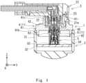
- Fig. 1 is a cross-sectional view showing the state of use of a floating connector assembly according to this embodiment.
- a floating connector assembly 1 according to this embodiment can be used to electrically connect an output connector 2, which is a typical example of first equipment, and an imaging unit 3, which is a typical example of second equipment. Note that, however, the first equipment and the second equipment to be electrically connected by the floating connector assembly 1 are not particularly limited.
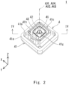
- Fig. 2 is a perspective view of the floating connector assembly according to the embodiment when viewed from the positive side of the z axis.
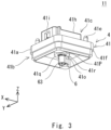
- Fig. 3 is a perspective view of a floating connector according to the embodiment when viewed from the negative side of the z axis.
- Fig. 4 is a cross-sectional view along line IV-IV in Fig. 2 .
- Fig. 5 is an enlarged view of a part V shown in Fig. 4 .
- the floating connector assembly 1 includes a first connector 4, a second connector 5, and a relay connector 6.
- the first connector 4 and the relay connector 6 constitute a floating connector 11.
- Fig. 6 is an exploded view of the first connector.
- the first connector 4 includes a first housing 41, a ground terminal (second terminal) 42, a first potting 43, a second housing (retaining member) 44, a signal terminal 45, and a second potting 46.
- Fig. 7 is a perspective view of the first housing of the first connector when viewed from the positive side of the z axis.
- the first housing 41 is an insulating resin molded object, for example.
- the first housing 41 holds a ground terminal 42 and a signal terminal 45.
- the first housing 41 includes a base part 41a, a first insert-receiving part 41b, a second insert-receiving part 41c, and a penetration part 41d.
- the base part 41a has a plate shape substantially parallel to the xy-plane.
- the base part 41a has a substantially rectangular shape when viewed from the z axis direction, for example.
- a fixing part 41e for fixing a fixing jig or the like, which is not shown, is preferably formed in the base part 41a.
- the fixing part 41e projects on the positive side of the z axis from the base part 41a, and it is disposed at a corner of the base part 41a, for example.
- the fixing part 41e has a substantially cylindrical shape, for example.
- the first insert-receiving part 41b has a structure into which a part of the housing 31 on the positive side of the z axis in the imaging unit 3 can be inserted.
- the first insert-receiving part 41b has a tubular shape that projects on the negative side of the z axis from the base part 41a and is disposed along the edge of the base part 41a.
- a step part 41f is preferably formed at the boundary between the base part 41a and the first insert-receiving part 41b.
- the second insert-receiving part 41c has a structure into which a housing 21 of the output connector 2 can be inserted. As shown in Fig. 7 , the second insert-receiving part 41c includes a first tubular part 41g and a second tubular part 41h.
- the first tubular part 41g projects on the positive side of the z axis from the base part 41a, and it is disposed substantially at the center of the base part 41a when viewed from the z axis direction.
- the first tubular part 41g has a substantially rectangular shape when viewed from the z axis direction, for example.
- the second tubular part 41h projects on the positive side of the z axis from the base part 41a, and it surrounds the first tubular part 41g.
- the second tubular part 41h is disposed substantially at the center of the base part 41a when viewed from the z axis direction, and it has a substantially convex shape that projects on the positive side of the y axis, for example.
- an engaged part 41i with which an engagement part 21a of the housing 21 of the output connector 2 is engaged is preferably formed in a part of the second tubular part 41h on the positive side of the y axis, as shown in Fig. 1 .
- the engaged part 41i is a penetrating hole that penetrates the part of the second tubular part 41h on the positive side of the y axis, and it has a substantially rectangular shape when viewed from the y axis direction, for example.
- the penetration part 41d penetrates the first housing 41 in the z axis direction.
- the penetration part 41d includes a first part 41j and a second part 41k.
- the first part 41j is an internal space of the first tubular part 41g of the second insert-receiving part 41c, and it has a substantially rectangular pillar shape, for example.
- the second part 41k penetrates the base part 41a in the z axis direction and is continuous with the first part 41j.
- the second part 41k is disposed on the negative side of the z axis relative to the first part 41j.
- the second part 41k is disposed substantially at the center of the first part 41j when viewed from the z axis direction, and it has a substantially cylindrical shape, for example.
- the second part 41k preferably includes a minor diameter part 411 and a major diameter part 41m.
- the edge of the minor diameter part 411 and the edge of the major diameter part 41m are arranged in a substantially concentric fashion when viewed from the z axis direction.
- the minor diameter part 411 is disposed on the negative side of the z axis relative to the major diameter part 41m.
- a step part 41n is formed at the boundary between the minor diameter part 411 and the major diameter part 41m.
- the end of the second part 41k on the negative side of the z axis is preferably narrowed by a stopper part 41o formed at the end of the base part 41a on the negative side of the z axis.
- the stopper part 41o projects on the negative side of the z axis from the base part 41a as shown in Fig. 3 , for example.
- the stopper part 41o includes a tubular part 41p and a circular part 41q.
- the tubular part 41p projects on the negative side of the z axis from the base part 41a.
- the tubular part 41p has a substantially cylindrical shape, for example, and an internal space of the tubular part 41p forms a part of the second part 41k of the penetration part 41d on the negative side of the z axis.
- the circular part 41q has a plate shape substantially parallel to the xy-plane, and it has a substantially circular ring shape when viewed from the z axis direction, for example.
- the outer edge of the circular part 41q is continuous with the end of the tubular part 41p on the negative side of the z axis.
- a penetration part 41r of the circular part 41q forms a narrowed part at the end of the second part 41k on the negative side of the z axis in the penetration part 41d.
- the edge of the second part 41k of the penetration part 41d and the edge of the penetration part 41r of the circular part 41q in the stopper part 41o are arranged in a substantially concentric fashion when viewed from the z axis direction.
- a spherical part 41s is preferably formed at a part on the positive side of the z axis around the penetration part 41r of the circular part 41q as shown in Figs. 5 and 7 .
- the spherical part 41s has a concave shape on the negative side of the z axis. As shown in Fig. 5 , a center C1 of the spherical part 41s is at substantially the same position as a center C2 of a spherical part 42c of the ground terminal 42, which is described later.
- the diameter of the spherical part 41s may be any diameter.
- Fig. 8 is a perspective view of the ground terminal of the first connector when viewed from the negative side of the z axis.
- the ground terminal 42 has electrical conductivity, and it is electrically connected to a ground terminal 22 of the output connector 2 as shown in Fig. 1 .
- the ground terminal 42 is inserted into the penetration part 41d of the first housing 41.
- the ground terminal 42 has a substantially cylindrical shape, for example, and includes a first part 42a, a second part 42b, a spherical part 42c, a first projecting part 42d, and a second projecting part 42e.
- the first part 42a is disposed in the minor diameter part 411 of the second part 41k of the penetration part 41d in the first housing 41.
- the outside diameter of the first part 42a is substantially equal to the diameter of the minor diameter part 411 of the second part 41k of the penetration part 41d in the first housing 41.
- the height in the z axis direction of the first part 42a is substantially equal to the height in the z axis direction of the minor diameter part 41l of the second part 41k of the penetration part 41d in the first housing 41.
- the second part 42b is disposed on the positive side of the z axis relative to the first part 42a, and it lies across the first part 41j of the penetration part 41d and the major diameter part 41m of the second part 41k in the first housing 41.
- the outside diameter of the second part 42b is smaller than the outside diameter of the first part 42a.
- a step part 42f is formed at the boundary between the first part 42a and the second part 42b.
- the height of the second part 42b in the z axis direction is substantially equal to the total height in the z axis direction of the first part 41j of the penetration part 41d and the major diameter part 41m of the second part 41k in the first housing 41.
- the spherical part 42c is formed on the inner periphery of the ground terminal 42.
- the spherical part 42c is disposed on a part of the ground terminal 42 on the negative side of the z axis.
- the spherical part 42c has a concave shape to the outside of the ground terminal 42 in the radial direction.
- a center C2 of the spherical part 42c is disposed on a center axis AX1 of the ground terminal 42 and substantially at the center of the height in the z axis direction of the first part 42a of the ground terminal 42.
- the diameter of the spherical part 42c may be any diameter.
- the first projecting part 42d projects inward in the radial direction of the ground terminal 42 from the inner periphery of the ground terminal 42.
- the first projecting part 42d has a substantially circular ring shape when viewed from the z axis direction, for example.
- the first projecting part 42d is disposed at the end of the spherical part 42c on the positive side of the z axis.
- the second projecting part 42e projects outward in the radial direction of the first part 42a from the outer periphery of the first part 42a.
- the second projecting part 42e has a substantially circular ring shape when viewed from the z axis direction, for example.
- the second projecting part 42e is in strong contact with the periphery of the minor diameter part 41l of the second part 41k of the penetration part 41d in the first housing 41 as shown in Fig. 5 , and thereby the ground terminal 42 is held by the first housing 41.
- the first potting 43 is a waterproof sealing material, for example, and Fig. 6 shows its hardened state. In the state where the ground terminal 42 is inserted into the penetration part 41d of the first housing 41, the first potting 43 is applied around the step part 42f of the ground terminal 42 and hardened as shown in Fig. 5 , which prevents water or the like from getting into the gap between the first part 42a of the ground terminal 42 and the penetration part 41d of the first housing 41.
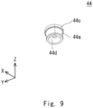
- Fig. 9 is a perspective view of the second housing of the first connector when viewed from the negative side of the z axis.
- the second housing 44 is an insulating resin molded object, for example, and it is inserted into the ground terminal 42 as shown in Fig. 5 .
- the second housing 44 includes a tubular part 44a, a projecting part 44b, and a flange part 44c.
- the tubular part 44a lies across the first projecting part 42d of the ground terminal 42.
- the tubular part 44a has a substantially cylindrical shape.
- the outside diameter of the tubular part 44a is substantially equal to the diameter of the inside of the first projecting part 42d in the ground terminal 42.
- the projecting part 44b projects inward in the radial direction of the tubular part 44a from the inner periphery of the tubular part 44a.
- the projecting part 44b has a substantially circular ring shape when viewed from the z axis direction, for example.
- the projecting part 44b is substantially at the center of the height in the z axis direction of the tubular part 44a.
- the flange part 44c is disposed on the positive side of the z axis relative to the first projecting part 42d of the ground terminal 42. As shown in Figs. 6 and 9 , the flange part 44c projects outward in the radial direction of the tubular part 44a from the outer periphery of the tubular part 44a.
- the flange part 44c has a substantially circular ring shape when viewed from the z axis direction, for example.
- the flange part 44c is disposed at the end of the tubular part 44a on the positive side of the z axis.
- the outside diameter of the flange part 44c is substantially equal to the inside diameter of the second part 42b of the ground terminal 42.
- the flange part 44c is in strong contact with the inner periphery of the second part 42b of the ground terminal 42, and thereby the second housing 44 is held by the ground terminal 42.
- a spherical part 44d is preferably formed at the end of the second housing 44 on the negative side of the z axis as shown in Fig. 9 .
- the spherical part 44d has a concave shape on the positive side of the z axis.
- a center C3 of the spherical part 44d is disposed at substantially the same position as the center C2 of the spherical part 42c of the ground terminal 42.
- the diameter of the spherical part 44d may be any diameter.
- the signal terminal 45 has electrical conductivity, and it is electrically connected to a signal terminal 23 of the output connector 2 as shown in Fig. 1 . As shown in Fig. 5 , the signal terminal 45 is inserted into the tubular part 44a of the second housing 44.
- the signal terminal 45 includes a pillar part 45a and a flange part 45b, for example.
- the pillar part 45a lies across the projecting part 44b of the second housing 44.
- the pillar part 45a has a substantially cylindrical shape, for example.
- the diameter of the pillar part 45a is substantially equal to the diameter of the inside of the projecting part 44b of the second housing 44.
- the end of the pillar part 45a on the positive side of the z axis is disposed at substantially the same height as the end of the ground terminal 42 on the positive side of the z axis as shown in Fig. 5 . Further, a part of the pillar part 45a on the negative side of the z axis projects on the negative side of the z axis from the second housing 44.
- the flange part 45b is disposed on the positive side of the z axis relative to the projecting part 44b of the second housing 44. As shown in Fig. 6 , The flange part 45b projects outward in the radial direction of the pillar part 45a from the outer periphery of the pillar part 45a. The flange part 45b is disposed substantially at the center of the height in the z axis direction of the pillar part 45a.
- the flange part 45b has a substantially circular ring shape when viewed from the z axis direction. As shown in Fig. 5 , the outside diameter of the flange part 45b is substantially equal to the diameter of the inside of the tubular part 44a of the second housing 44. In the state where the signal terminal 45 is inserted into the tubular part 44a of the second housing 44, the flange part 45b is in strong contact with the inner periphery of the tubular part 44a of the second housing 44, and thereby the signal terminal 45 is held by the second housing 44.
- the second potting 46 is a waterproof sealing material, for example, and Fig. 6 shows its hardened state. In the state where the signal terminal 45 is inserted into the tubular part 44a of the second housing 44, the second potting 46 is applied to the end of the second housing 44 on the positive side of the z axis and hardened as shown in Fig. 5 , which prevents water or the like from getting into the gap between the ground terminal 42 and the second housing 44 and the gap between the signal terminal 45 and the second housing 44.
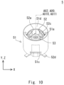
- Fig. 10 is a perspective view of the second connector when viewed from the positive side of the z axis.
- Fig. 11 is an exploded view of the second connector.
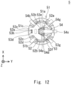
- Fig. 12 is a view of the second connector when viewed from the negative side of the z axis.
- the second connector 5 includes a first housing 51, a ground terminal 52, a second housing 53, and a signal terminal 54.
- the first housing 51 is an insulating resin molded object, for example. As shown in Figs. 10 and 11 , the first housing 51 has a substantially cylindrical shape. The first housing 51 has a groove 51a on its inner periphery. As shown in Fig. 12 , the groove 51a extends in the z axis direction, and disposed so as to be opposed in the x axis direction.
- the first housing 51 has a hollow 51b on its inner periphery.
- the hollow 51b extends in the z axis direction, for example, and it has a substantially rectangular shape when viewed from a center axis AX2 of the first housing 51 to the outside in the radial direction of the first housing 51.
- the hollows 51b are disposed at substantially equal intervals in the circumferential direction of the first housing 51.
- the first housing 51 has a notch 51c that is open to the negative side of the z axis at its end on the negative side of the z axis.
- the notch 51c has a substantially rectangular shape when viewed from the y axis direction, for example, and the notches 51c are disposed so as to be opposed in the y axis direction.
- an inclined surface 51d in a conical shape that is inclined to the negative side of the z axis toward the center axis AX2 side of the first housing 51 is formed.
- the ground terminal 52 has electrical conductivity, and it is electrically connected to a board 32 of the imaging unit 3 as shown in Fig. 1 . As shown in Fig. 10 , the ground terminal 52 is inserted into the first housing 51. As shown in Fig. 11 , the ground terminal 52 includes a tubular part 52a, a first contact spring part 52b, a second contact spring part 52c, a leg part 52d, and an insertion part 52e.
- the tubular part 52a is disposed inside the first housing 51.
- the tubular part 52a has a substantially cylindrical shape.
- the outside diameter of the tubular part 52a is substantially equal to the inside diameter of the first housing 51.
- the end of the tubular part 52a on the positive side of the z axis is disposed at substantially the same height as the end of the inclined surface 51d on the inside diameter side in the first housing 51 as shown in Fig. 10 .
- the first contact spring part 52b is disposed inside the groove 51a of the tubular part 52a. As shown in Fig. 11 , the first contact spring part 52b is disposed inside a first opening 52f in the tubular part 52a.
- the first contact spring part 52b has a plate shape, and the end of the first contact spring part 52b on the positive side of the z axis is connected to the end of the first opening 52f of the tubular part 52a on the positive side of the z axis.
- the first contact spring part 52b has an inclined part 52g that is inclined outward in the radial direction of the tubular part 52a toward the negative side of the z axis, and a flat part 52h that extends to the negative side of the z axis from the inclined part 52g.
- the first contact spring part 52b is disposed so as to be opposed in the x axis direction, and in the state where the ground terminal 52 is inserted into the first housing 51, the flat part 52h of the first contact spring part 52b is in contact with the bottom surface of the groove 51a of the first housing 51.
- the second contact spring part 52c is disposed so as to be opposed to the hollow 51b of the first housing 51. As shown in Fig. 11 , the second contact spring part 52c is disposed inside a second opening 52i in the tubular part 52a.
- the second contact spring part 52c has a plate shape, and the end of the second contact spring part 52c on the negative side of the z axis is connected to the end of the second opening 52i of the tubular part 52a on the negative side of the z axis.
- the second contact spring part 52c has a corrugated shape when viewed from the circumferential direction of the tubular part 52a.
- the second contact spring part 52c includes a first curve part 52j that projects inward in the radial direction of the tubular part 52a and a second curve part 52k that is disposed on the negative side of the z axis relative to the first curve part 52j and projects outward in the radial direction of the tubular part 52a.
- the second contact spring parts 52c are disposed at substantially equal intervals in the circumferential direction of the tubular part 52a, and in the state where the ground terminal 52 is inserted into the first housing 51, the second curve part 52k of the second contact spring parts 52c is in contact with the bottom surface of the hollow 51b of the first housing 51.
- first contact spring part 52b and the second contact spring parts 52c come into contact with the inner periphery of the first housing 51, and thereby the ground terminal 52 is held by the first housing 51.
- first contact spring part 52b and the second contact spring parts 52c can be formed by cutting out and bending the tubular part 52a.
- the leg part 52d is disposed on the negative side of the z axis relative to the first housing 51. As shown in Fig. 11 , the leg part 52d projects outward in the radial direction of the tubular part 52a from the end of the tubular part 52a on the negative side of the z axis.
- the leg parts 52d are disposed at substantially equal intervals in the circumferential direction of the tubular part 52a. In the state where the ground terminal 52 is inserted into the first housing 51, the leg part 52d is drawn from the outer periphery of the first housing 51 as shown in Fig. 12 .
- the insertion part 52e is disposed inside a notch 52m formed at the end of the tubular part 52a on the negative side of the z axis.
- the insertion part 52e has a plate shape, and the end of the insertion part 52e on the positive side of the z axis is connected to the end of the notch 52m of the tubular part 52a on the positive side of the z axis.
- the insertion part 52e has a substantially rectangular shape when viewed from the y axis direction, for example.
- the insertion part 52e preferably has a first projecting part 52n that projects outward in the radial direction of the tubular part 52a from the insertion part 52e. Further, the insertion part 52e preferably has a second projecting part 52o that projects in the circumferential direction of the tubular part 52a from the insertion part 52e.
- the second housing 53 is an insulating resin molded object, for example. As shown in Figs. 10 and 12 , the second housing 53 is inserted into the tubular part 52a of the ground terminal 52. As shown in Fig. 11 , the second housing 53 includes a tubular part 53a, a flange part 53b, a projecting part 53c, and an insert-receiving part 53d.
- the tubular part 53a is disposed inside the tubular part 52a of the ground terminal 52.
- the tubular part 53a has a substantially cylindrical shape.
- grooves 53e may be disposed at substantially equal intervals in the circumferential direction of the tubular part 53a.
- the flange part 53b is disposed inside the tubular part 52a of the ground terminal 52. As shown in Fig. 11 , the flange part 53b projects outward in the radial direction of the tubular part 53a from the outer periphery of the tubular part 53a.
- the flange part 53b has a substantially circular ring shape when viewed from the z axis direction, for example.
- the flange part 53b is disposed at the end of the tubular part 53a on the negative side of the z axis.
- an insert-receiving part 53f is preferably formed to be continuous with the inside of the tubular part 53a.
- the insert-receiving part 53f extends in the x axis direction so as to lie across the inside of the tubular part 53a.
- the insert-receiving part 53f has a substantially rectangular shape when viewed from the z axis direction, for example, and the insert-receiving part 53f is open to the negative side of the z axis.
- a hollow 53g is preferably formed at the end of the tubular part 53a and the flange part 53b on the negative side of the z axis.
- the hollow 53g extends on the positive side of the y axis from the inside of the tubular part 53a.
- the hollow 53g has a substantially convex shape that projects on the positive side of the y axis when viewed from the z axis direction, for example, and the hollow 53g is open to the negative side of the z axis.
- the projecting part 53c passes through the notch 51c on the negative side of the y axis of the first housing 51. As shown in Fig. 11 , the projecting part 53c projects outward in the radial direction of the flange part 53b from the outer periphery of the flange part 53b. The projecting part 53c is disposed at the end of the tubular part 53a on the negative side of the z axis and opposed in the y axis direction.
- the insert-receiving part 53d is a penetration part that is formed in the projecting part 53c on the negative side of the y axis.
- the insert-receiving part 53d extends in the z axis direction.
- the insert-receiving part 53d preferably has a projecting part 53h that projects from the inner periphery of the insert-receiving part 53d. In the state where the second housing 53 is inserted into the ground terminal 52, the insertion part 52e of the ground terminal 52 is inserted into the insert-receiving part 53d.
- the projecting part 53h of the insert-receiving part 53d of the second housing 53 presses the insertion part 52e on the positive side of the y axis through the first projecting part 52n of the ground terminal 52, and the insertion part 52e of the ground terminal 52 is interposed between the projecting part 53h of the insert-receiving part 53d of the second housing 53 and the end of the inner periphery of the insert-receiving part 53d on the positive side of the y axis.
- the second projecting part 52o of the insertion part 52e in the ground terminal 52 is in strong contact with the inner periphery of the insert-receiving part 53d of the second housing 53.
- the second housing 53 is thereby held by the ground terminal 52.
- the signal terminal 54 has electrical conductivity, and it is inserted into the tubular part 53a of the second housing 53 as shown in Fig. 12 .
- the signal terminal 54 includes a tubular part 54a, a contact spring part 54b, a leg part 54c, and an insertion part 54d.
- the tubular part 54a is disposed inside the tubular part 53a of the second housing 53.
- the tubular part 54a has a substantially cylindrical shape, for example.
- the contact spring part 54b is disposed inside the tubular part 53a of the second housing 53.
- the contact spring parts 54b are disposed at substantially equal intervals in the circumferential direction of the tubular part 54a when viewed from the z axis direction.
- the contact spring part 54b has a plate shape, and it includes a curve part 54e that projects inward in the radial direction of the tubular part 54a, for example, and a connection part 54f that extends on the negative side of the z axis from the curve part 54e.
- the end of the connection part 54f on the negative side of the z axis is connected to the end of the tubular part 54a on the positive side of the z axis.
- the contact spring part 54b projects on the positive side of the z axis from the tubular part 54a.
- the leg part 54c is drawn from the inside of the tubular part 53a of the second housing 53 to the outside of the first housing 51 through the hollow 53g and the notch 51c of the first housing 51 on the positive side of the y axis.
- the leg part 54c is substantially L-shaped when viewed from the x axis direction, and the end of the leg part 54c on the positive side of the z axis is connected to the end of the tubular part 54a on the negative side of the z axis.
- the insertion part 54d is inserted into the insert-receiving part 53f of the second housing 53. As shown in Fig. 11 , the insertion part 54d projects on the positive side and on the negative side of the x axis from the leg part 54c.
- the insertion part 54d has a substantially rectangular shape when viewed from the y axis direction, for example.
- the insertion part 54d is disposed substantially at the center of the height in the z axis direction of the part of the leg part 54c extending in the z axis direction.
- the insertion part 54d preferably has a projecting part 54g that projects on the positive side of the y axis from the insertion part 54d.
- the insertion part 54d In the state where the signal terminal 54 is inserted into the tubular part 53a of the second housing 53, the insertion part 54d is in strong contact with the periphery of the insert-receiving part 53f of the second housing 53 with the projecting part 54g of the insertion part 54d interposed therebetween, and thereby the signal terminal 54 is held by the second housing 53.
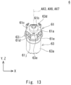
- Fig. 13 is a perspective view of a relay connector when viewed from the positive side of the z axis.
- Fig. 14 is an exploded view of the relay connector.
- Fig. 15 is a perspective view of the relay connector when viewed from the negative side of the z axis.
- the relay connector 6 electrically connects the first connector 4 and the second connector 5.
- the relay connector 6 includes a housing (holding member) 61, a signal terminal 62, and a ground terminal (first terminal) 63.
- Fig. 16 is a perspective view of the housing of the relay connector when viewed from the negative side of the z axis.
- the housing 61 is an insulating resin molded object, for example. As shown in Figs. 14 and 16 , the housing 61 includes a tubular part 61a, a first spherical part 61b, a flange part 61c, a wall part 61d, and a second spherical part 61e.
- the tubular part 61a has a substantially cylindrical shape.
- an insert-receiving part 61f is formed to be continuous with the inside of the tubular part 61a.
- the insert-receiving part 61f extends in the x axis direction so as to lie across the inside of the tubular part 61a.
- the insert-receiving part 61f has a substantially rectangular shape when viewed from the z axis direction, and the insert-receiving part 61f is open to the negative side of the z axis.
- grooves 61g may be formed at substantially equal intervals in the circumferential direction of the tubular part 61a as shown in Fig. 15 .
- the first spherical part 61b is formed at the end of the tubular part 61a on the positive side of the z axis, and a penetration part 61h is formed at substantially the center of the first spherical part 61b when viewed from the z axis direction.
- the penetration part 61h is continuous with the inside of the tubular part 61a, and it has a substantially cylindrical shape, for example.
- the outside diameter (inside diameter) of the tubular part 61a and the edge of the penetration part 61h are arranged in a substantially concentric fashion when viewed from the z axis direction.
- the first spherical part 61b is convex on the positive side of the z axis.
- the diameter of the first spherical part 61b is substantially equal to the diameter of the spherical part 44d of the second housing 44 in the first connector 4.
- the flange part 61c projects outward in the radial direction of the tubular part 61a from the outer periphery of the tubular part 61a.
- the flange part 61c has a substantially rectangular shape when viewed from the z axis direction, for example, and each edge of the flange part 61c curves along the inner peripheral shape of the first part 42a of the ground terminal 42 in the first connector 4.
- a circle that is formed by connecting the rim of the flange part 61c and the edge of the penetration part 61h of the first spherical part 61b are arranged in a substantially concentric fashion when viewed from the z axis direction.
- the flange part 61c is disposed in the part of the tubular part 61a on the positive side of the z axis.
- an inclined surface 61i that is inclined outward in the radial direction of the tubular part 61a toward the positive side of the z axis is formed.
- the inclined surface 61i is disposed between the edges of the flange part 61c.
- an insert-receiving part 61j is formed in the flange part 61c.
- the insert-receiving part 61j penetrates the flange part 61c in the z axis direction, and it has a substantially rectangular pillar shape when viewed from the z axis direction, for example.
- the wall part 61d extends on the negative side of the z axis from each edge of the flange part 61c and also projects outward in the radial direction of the tubular part 61a from the outer periphery of the tubular part 61a.
- the side surface of the wall part 61d curves to be continuous with each edge of the flange part 61c when viewed in the z axis direction.
- the second spherical part 61e is formed at the end of the wall part 61d on the negative side of the z axis.
- the second spherical part 61e is convex on the negative side of the z axis.
- the diameter of the second spherical part 61e is substantially equal to the diameter of the spherical part 41s of the first housing 41 in the first connector 4.
- the signal terminal 62 has electrical conductivity, and it is inserted into the tubular part 61a of the housing 61 as shown in Fig. 5 .
- the signal terminal 62 includes a tubular part 62a, a contact spring part 62b, an insertion part 62c, and a pillar part 62d.
- the tubular part 62a is disposed inside the tubular part 61a of the housing 61.
- the tubular part 62a has a substantially cylindrical shape, for example.
- the contact spring part 62b is disposed inside the tubular part 61a of the housing 61. As shown in Fig. 14 , the contact spring parts 62b are disposed at substantially equal intervals in the circumferential direction of the tubular part 62a when viewed from the z axis direction.
- the contact spring part 62b has a plate shape, and the end of the contact spring part 62b on the negative side of the z axis is connected to the end of the tubular part 61a on the positive side of the z axis.
- the contact spring part 62b has a corrugated shape when viewed from the circumferential direction of the tubular part 62a.
- the contact spring part 62b includes a first curve part 62e that projects inward in the radial direction of the tubular part 62a and a second curve part 62f that is disposed on the negative side of the z axis relative to the first curve part 62e and projects outward in the radial direction of the tubular part 62a.
- the insertion part 62c is inserted into the insert-receiving part 61f of the housing 61.
- the insertion part 62c has a substantially lying H shape when viewed from the y axis direction, and the end of the insertion part 62c on the positive side of the z axis is connected to the end of the tubular part 62a on the negative side of the z axis.
- the insertion part 62c is disposed on the negative side of the y axis of the tubular part 62a.
- the insertion part 62c In the state where the insertion part 62c is inserted into the insert-receiving part 61f of the housing 61, the insertion part 62c is in strong contact with the periphery of the insert-receiving part 61f of the housing 61, and thereby the signal terminal 62 is held by the housing 61.
- the pillar part 62d projects on the negative side of the z axis from the housing 61.
- the pillar part 62d has a substantially cylindrical shape, for example, and the end of the pillar part 62d on the negative side of the z axis is narrowed as shown in Fig. 14 .
- the pillar part 62d extends on the negative side of the z axis from the insertion part 62c.
- the pillar part 62d is disposed substantially at the center of the width in the x axis direction of the insertion part 62c.
- the outer periphery (inner periphery) of the pillar part 62d and the outer periphery (inner periphery) of the tubular part 62a are arranged in a substantially concentric fashion when viewed from the z axis direction.
- the ground terminal 63 has electrical conductivity, and it surrounds the housing 61 as shown in Fig. 13 .
- the ground terminal 63 includes a first tubular part 63a, a second tubular part 63b, a connection part 63c, a contact spring part 63d, and an insertion part 63e.
- the first tubular part 63a has a substantially cylindrical shape, for example.
- the second tubular part 63b is disposed on the positive side of the z axis relative to the first tubular part 63a, and it has a substantially cylindrical shape, for example.
- the outside diameter of the second tubular part 63b is smaller than the outside diameter of the first tubular part 63a as shown in Fig. 14 .
- the inside diameter of the second tubular part 63b is smaller than the inside diameter of the first tubular part 63a as shown in Fig. 5 .
- the outer periphery (inner periphery) of the first tubular part 63a and the outer periphery (inner periphery) of the second tubular part 63b are arranged in a substantially concentric fashion when viewed from the z axis direction.
- connection part 63c connects the first tubular part 63a and the second tubular part 63b.
- the connection part 63c has a substantially conical shape that tapers inward in the radial direction of the connection part 63c toward the positive side of the z axis.
- the connection part 63c may have an opening 63f.
- the contact spring part 63d covers the inclined surface 61i of the housing 61, and is disposed on the positive side of the z axis relative to the second spherical part 61e of the housing 61.
- the contact spring parts 63d are disposed at substantially equal intervals in the circumferential direction of the second tubular part 63b when viewed in the z axis direction.
- the contact spring part 63d has a plate shape, and the end of the contact spring part 63d on the negative side of the z axis is connected to the end of the second tubular part 63b on the positive side of the z axis.
- the contact spring part 63d curves to project outward in the radial direction of the second tubular part 63b when viewed in the circumferential direction of the second tubular part 63b.
- the contact spring part 63d includes a curve part 63g that curves outward in the radial direction of the second tubular part 63b, and a connection part (inclined part) 63h that connects the curve part 63g and the second tubular part 63b and it is inclined outward in the radial direction of the second tubular part 63b toward the positive side of the z axis.
- the connection part 63h is inclined along the inclined surface 61i of the housing 61.
- the curvature of the lateral surface (i.e., the surface of the second tubular part 63b on the outer side in the radial direction) of the curve part 63g of the contact spring part 63d is preferably greater than the curvature of the spherical part 42c of the ground terminal 42 of the first connector 4 as shown in Fig. 5 .
- the lateral surface of the curve part 63g of the contact spring part 63d preferably has a contact point 63i that projects outward in the radial direction of the second tubular part 63b from the lateral surface of the curve part 63g, as shown in Fig. 14 .
- a projecting surface of the contact point 63i is spherical, and the curvature of the projecting surface of the contact point 63i is greater than the curvature of the spherical part 42c of the ground terminal 42 of the first connector 4.
- the distance between the external end in the radial direction of the second tubular part 63b in the contact point 63i and a center line AX3 of the ground terminal 63 is preferably slightly larger than the radius of the spherical part 42c of the ground terminal 42 of the first connector 4.
- the insertion part 63e is inserted into the insert-receiving part 61j of the housing 61. As shown in Fig. 14 , the insertion part 63e projects on the positive side of the z axis from the second tubular part 63b. The insertion part 63e is disposed on the negative side of the y axis of the second tubular part 63b.
- the insertion part 63e has a plate shape, and it has a substantially rectangular shape when viewed from the y axis direction, for example.
- the insertion part 63e preferably has a projecting part 63j that projects on the negative side of the y axis from the insertion part 63e.
- the insertion part 63e In the state where the insertion part 63e is inserted into the insert-receiving part 61j of the housing 61, the insertion part 63e is in strong contact with the periphery of the insert-receiving part 61j of the housing 61 with the projecting part 63j of the insertion part 63e interposed therebetween, and thereby the ground terminal 63 is held by the housing 61.
- the end of the ground terminal 63 on the negative side of the z axis is disposed at substantially the same height as the end of the signal terminal 62 on the negative side of the z axis as shown in Fig. 5 .
- Fig. 17 is a view illustrating the flow of electrically connecting the first connector and the relay connector.
- the cross-sectional position in Fig. 17 corresponds to that in Fig. 4 .
- the signal terminal 45 of the first connector 4 is inserted into the second housing 44 from the positive side of the z axis, and the flange part 45b of the signal terminal 45 is inserted into the second housing 44 until the flange part 45b of the signal terminal 45 comes into substantial contact with the projecting part 44b of the second housing 44, and thereby the signal terminal 45 and the second housing 44 are fixed to each other.
- the second housing 44 to which the signal terminal 45 is fixed is inserted into the ground terminal 42 from the positive side of the z axis, and the flange part 44c of the second housing 44 is inserted into the ground terminal 42 until the flange part 44c of the second housing 44 comes into substantial contact with the first projecting part 42d of the ground terminal 42, and thereby the second housing 44 and the ground terminal 42 are fixed to each other.
- a part of the first connector 4 is thereby assembled.
- a center axis AX1 of the ground terminal 42, a center axis AX4 of the second housing 44, and a center axis AX5 of the signal terminal 45 are substantially coaxially arranged.
- the part of the relay connector 6 on the positive side of the z axis including the insertion part 62c of the signal terminal 62 is inserted into the housing 61 from the negative side of the z axis, and the insertion part 62c of the signal terminal 62 is inserted into the insert-receiving part 61f of the housing 61, and thereby the housing 61 and the signal terminal 62 are fixed to each other.
- the contact spring part 62b of the signal terminal 62 is disposed along the edge of the penetration part 61h of the housing 61 when viewed from the z axis direction. Further, the pillar part 62d of the signal terminal 62 is disposed inside the penetration part 61h of the housing 61 when viewed from the z axis direction.
- the part of the housing 61 on the negative side of the z axis is inserted into the ground terminal 63 so that the contact spring part 63d of the ground terminal 63 is disposed between the wall parts 61d of the housing 61, and further the insertion part 63e of the ground terminal 63 is inserted into the insert-receiving part 61j of the housing 61, and thereby the housing 61 and the ground terminal 63 are fixed to each other.
- the relay connector 6 is thereby assembled.
- the center axis AX3 of the ground terminal 63, the center axis AX6 of the signal terminal 62, and the center axis AX7 of the housing 61 are substantially coaxially arranged.
- the relay connector 6 is inserted into the first connector 4.
- the relay connector 6 is inserted through the opening on the positive side of the z axis of the penetration part 41d of the first housing 41 of the first connector 4.
- a first spherical contact part 7 (see Fig. 4 ) is formed by the spherical part 41s of the first housing 41 and the housing 61 of the relay connector 6.
- the penetration part 41d of the first housing 41 of the first connector 4 has a shape to which the relay connector 6 can be inserted from the positive side of the z axis. Further, the penetration part 41r of the first housing 41 of the first connector 4 allows the relay connector 6 to rotate at a specified angle with respect to the center C1 of the spherical part 41s (i.e., the first spherical contact part 7) of the first housing 41 of the first connector 4, as described later, and it has a smaller radius than the distance between the external end in the radial direction of the tubular part 61a in the second spherical part 61e of the housing 61 of the relay connector 6 and the center line AX7 of the housing 61.
- the relay connector 6 thereby catches on the stopper part 41o of the first housing 41 of the first connector 4, which prevents the relay connector 6 from coming out from the first connector 4 to the negative side of the z axis.
- the ground terminal 42 that is fixed to the signal terminal 45 is inserted through the opening on the positive side of the z axis of the penetration part 41d of the first housing 41 of the first connector 4.
- the first part 42a of the ground terminal 42 is inserted into the minor diameter part 411 of the second part 41k of the penetration part 41d of the first housing 41, and the second projecting part 42e of the first part 42a of the ground terminal 42 is inserted into the minor diameter part 411 of the second part 41k of the penetration part 41d of the first housing 41 until the end of the ground terminal 42 on the negative side of the z axis comes into substantial contact with the stopper part 41o, and thereby the first housing 41 and the ground terminal 42 are fixed to each other.
- the center axis AX1 of the ground terminal 42, the center axis AX4 of the second housing 44, the center axis AX5 of the signal terminal 45, and the center axis AX8 of the first housing 41 are substantially coaxially arranged in the first connector 4.
- the pillar part 45a of the signal terminal 45 of the first connector 4 is inserted into the contact spring part 62b of the signal terminal 62 of the relay connector 6.
- the signal terminal 45 of the first connector 4 and the signal terminal 62 of the relay connector 6 are thereby electrically connected.
- the contact spring part 63d of the ground terminal 63 in the relay connector 6 is inserted into the part inside the ground terminal 42 on the negative side of the z axis in the first connector 4, and the contact point 63i of the contact spring part 63d comes into substantial point contact with the spherical part 42c of the ground terminal 42.
- a contact part P1 (see Fig. 5 ) is thereby made by the spherical part 42c of the ground terminal 42 of the first connector 4 and the contact point 63i of the contact spring part 63d of the ground terminal 63 of the relay connector 6, and the ground terminal 42 of the first connector 4 and the ground terminal 63 of the relay connector 6 are electrically connected.
- the contact point 63i Since the curvature of the contact point 63i is greater than the curvature of the spherical part 42c of the ground terminal 42 of the first connector 4 as described above, the contact point 63i adequately comes into substantial point contact with the spherical part 42c of the ground terminal 42 of the first connector 4.
- a second spherical contact part 8 (see Fig. 4 ) is formed by the spherical part 44d of the second housing 44 of the first connector 4 and the first spherical part 61b of the housing 61 of the relay connector 6.
- the housing 61 of the relay connector 6 is interposed between the spherical part 41s of the first housing 41 of the first connector 4 and the spherical part 44d of the second housing 44. Therefore, as shown in Fig. 5 , the center C1 of the spherical part 41s of the first housing 41 of the first connector 4, the center C2 of the spherical part 42c of the ground terminal 42, and the center C3 of the spherical part 44d of the second housing 44 (i.e., the second spherical contact part 8) are kept disposed at substantially the same positions.
- the relay connector 6 is rotatable at a specified angle with respect to the center C1 of the spherical part 41s of the first housing 41 of the first connector 4.
- the contact point 63i of the ground terminal 63 of the relay connector 6, i.e., the contact part P1 is disposed substantially on the diameter of the spherical part 41s of the first housing 41.
- the first potting 43 is applied to the step part 42f of the ground terminal 42 of the first connector 4, and also the second potting 46 is applied to the end of the second housing 44 on the positive side of the z axis in the first connector 4.
- the relay connector 6 is thereby inserted into the first connector 4, and an electrical connection is established between them. In other words, the floating connector 11 is thereby assembled.
- a process of assembling the second connector 5 is described hereinafter.
- the part of the signal terminal 54 on the positive side of the z axis including the insertion part 54d is inserted into the second housing 53 from the negative side of the z axis, and the insertion part 54d of the signal terminal 54 is inserted into the insert-receiving part 53f of the second housing 53, and thereby the second housing 53 and the signal terminal 54 are fixed to each other.
- the contact spring part 54b of the signal terminal 54 is disposed along the opening of the tubular part 53a of the second housing 53o on the positive side of the z axis when viewed from the z axis direction. Further, the leg part 54c of the signal terminal 54 is accommodated in the hollow 53g of the second housing 53.
- the tubular part 52a of the ground terminal 52 is inserted into the first housing 51 from the negative side of the z axis, and the flat part 52h of the first contact spring part 52b of the ground terminal 52 is brought into contact with the bottom surface of the groove 51a of the first housing 51, and also the second curve part 52k of the second contact spring part 52c is brought into contact with the bottom surface of the hollow 51b of the first housing 51, so that the first housing 51 and the ground terminal 52 are fixed to each other.
- the insertion part 52e of the ground terminal 52 is disposed at the notch 51c on the negative side of the y axis of the first housing 51. Further, the leg part 52d of the ground terminal 52 projects outward in the radial direction of the first housing 51 from the first housing 51.
- the tubular part 53a of the second housing 53 fixed to the signal terminal 54 is inserted from the negative side of the z axis into the tubular part 52a of the ground terminal 52 fixed to the first housing 51, and the insertion part 52e of the ground terminal 52 is inserted into the insert-receiving part 53d of the second housing 53.
- the first housing 51, the ground terminal 52, the second housing 53, and the signal terminal 54 are thereby integrally assembled.
- the leg part 54c of the signal terminal 54 projects outward in the radial direction of the first housing 51 from the notch 51c of the first housing 51 on the positive side of the y axis.
- the center axis AX2 of the first housing 51, a center axis AX9 of the ground terminal 52, a center axis AX10 of the second housing 53, and a center axis AX11 of the signal terminal 54 are substantially coaxially arranged.
- the output connector 2 has a structure in which the ground terminal 22 and the signal terminal 23 are accommodated in the housing 21.
- the ground terminal 42 of the first connector 4 is electrically connected to the ground terminal 22 of the output connector 2, and the signal terminal 45 of the first connector 4 is electrically connected to the signal terminal 23.
- the imaging unit 3 has a structure in which the board 32 on which an imaging element is mounted is accommodated in the housing 31.
- the leg part 52d of the ground terminal 52 of the second connector 5 and the leg part 54c of the signal terminal 54 are electrically connected to the board 32 of the imaging unit 3.
- the first tubular part 63a of the ground terminal 63 of the relay connector 6 is inserted into the tubular part 52a of the ground terminal 52 of the second connector 5 from the positive side of the z axis, and thereby the second contact spring part 52c of the ground terminal 52 of the second connector 5 is brought into contact with the outer periphery of the first tubular part 63a of the ground terminal 63 of the relay connector 6, so that the ground terminal 52 of the second connector 5 and the ground terminal 63 of the relay connector 6 are electrically connected.
- the pillar part 62d of the signal terminal 62 of the relay connector 6 is inserted into the contact spring part 54b of the signal terminal 54 of the second connector 5 from the positive side of the z axis, so that the signal terminal 54 of the second connector 5 and the signal terminal 62 of the relay connector 6 are electrically connected.
- the output connector 2 and the imaging unit 3 are thereby electrically connected through the first connector 4, the second connector 5, and the relay connector 6.
- connection state of the output connector 2 and the imaging unit 3 in the case where a connection axis AX12 between the output connector 2 and the first connector 4 and a connection axis AX13 between the imaging unit 3 and the second connector 5 are out of alignment is described hereinafter.
- Fig. 18 is a cross-sectional view showing the connection state of the output connector and the imaging unit when the connection axis between the output connector and the first connector and the connection axis between the imaging unit and the second connector are out of alignment.
- Fig. 19 is an enlarged view of a part XIX shown in Fig. 18 . Note that the cross-sectional position in Figs. 18 and 19 corresponds to that in Fig. 4 .
- the center C1 of the spherical part 41s of the first housing 41 of the first connector 4, the center C2 of the spherical part 42c of the ground terminal 42, and the center C3 of the spherical part 44d of the second housing 44 are disposed at substantially the same positions.
- the contact point 63i of the ground terminal 63 of the relay connector 6 is disposed substantially on the diameter of the spherical part 41s of the first housing 41.
- the distance between each contact point 63i of the ground terminal 63 of the relay connector 6 and the center C1 of the spherical part 41s of the first housing 41 of the first connector 4 does not substantially change, and when, as shown in Figs. 18 and 19 , the connection axis AX12 between the output connector 2 and the first connector 4 and the connection axis AX13 between the imaging unit 3 and the second connector 5 are out of alignment, the relay connector 6 rotates with respect to the center C1.
- the contact spring part 62b of the signal terminal 62 of the relay connector 6, and the second contact spring part 52c of the ground terminal 52 and the contact spring part 54b of the signal terminal 54 in the second connector 5 change in shape so as not to inhibit the rotation of the relay connector 6.
- connection axis AX12 between the output connector 2 and the first connector 4 and the connection axis AX13 between the imaging unit 3 and the second connector 5 are out of alignment, the stability of electrical connection is maintained since contact pressures of each contact point 63i of the ground terminal 63 of the relay connector 6 on the spherical part 41s of the first housing 41 of the first connector 4 are substantially the same.
- each contact point 63i of the ground terminal 63 of the relay connector 6 is inscribed in the spherical part 41s of the first housing 41 of the first connector 4, an increase in the size of the relay connector 6 is minimized, which achieves size reduction of the floating connector assembly 1 and the floating connector 11.
- the second spherical part 61e of the housing 61 of the relay connector 6 catches on the stopper part 41o of the first housing 41 of the first connector 4.
- the floating connector assembly 1 and the floating connector 11 according to this embodiment prevent the relay connector 6 from coming out of the first connector 4 when transporting the relay connector 6 fixed to the first connector 4, for example. Therefore, the floating connector assembly 1 and the floating connector 11 according to this embodiment reduce loss or damage of the relay connector 6 during transportation, for example.
- the curvature of the contact point 63i formed on the contact spring part 63d of the ground terminal 63 of the relay connector 6 is greater than the curvature of the spherical part 42c of the ground terminal 42 of the first connector 4.
- the contact point 63i adequately comes into substantial point contact with the spherical part 42c of the ground terminal 42 of the first connector 4. Therefore, in the floating connector assembly 1 and the floating connector 11 according to this embodiment, the relay connector 6 appropriately rotates with respect to the first connector 4.
- the housing 61 of the relay connector 6 is interposed between the first housing 41 and the second housing 44 of the first connector 4 so that the second spherical part 61e of the housing 61 of the relay connector 6 is in substantial spherical contact with the spherical part 41s of the first housing 41 of the first connector 4, and the first spherical part 61b of the relay connector 6 is in substantial spherical contact with the spherical part 44d of the second housing 44 of the first connector 4.
- the floating connector assembly 1 and the floating connector 11 allow maintaining the state where the center C1 of the spherical part 41s of the first housing 41 of the first connector 4, the center C2 of the spherical part 42c of the ground terminal 42, and the center C3 of the spherical part 44d of the second housing 44 are disposed at substantially the same positions. Further, the floating connector assembly 1 and the floating connector 11 according to this embodiment allow the contact point 63i of the ground terminal 63 of the relay connector 6 to be disposed substantially on the diameter of the spherical part 41s of the first housing 41.
- the relay connector 6 rotates with respect to the center C1 without a substantial change in the distance between each contact point 63i of the ground terminal 63 of the relay connector 6 and the center C1 of the spherical part 41s of the first housing 41 of the first connector 4.
- the contact point 63i is formed on the contact spring part 63d of the ground terminal 63 of the relay connector 6 in the above-described embodiment, the contact point 63i may be omitted.
- the curvature of the curve part 63g of the contact spring part 63d of the relay connector 6 is set to be greater than the curvature of the spherical part 42c of the ground terminal 42 of the first connector 4, and the curve part 63g of the contact spring part 63d of the relay connector 6 is brought into substantial point contact with the spherical part 42c of the ground terminal 42 of the first connector 4.
- the shapes of the signal terminal and the ground terminal of each connector are shown merely as typical examples, and the shapes of the signal terminal and the ground terminal of each connector are not particularly limited as long as at least the contact spring part 63d of the relay connector 6 comes into contact with the spherical part 42c of the ground terminal 42 of the first connector 4 and the relay connector 6 is rotatable.
- the shape of the first housing 41 of the first connector 4 is merely a typical example, and it can be modified as appropriate according to the shape of first equipment and second equipment connected thereto.
- the stopper part 41o is formed on the first housing 41 of the first connector 4 in the above-described embodiment, the stopper part 41o may be omitted.
- the connection part 63h of the contact spring part 63d of the ground terminal 63 in the relay connector 6 is inclined outward in the radial direction of the second tubular part 63b toward the positive side of the z axis.
- the contact spring part 63d of the relay connector 6 When the contact spring part 63d of the relay connector 6 is about to come out of the spherical part 42c of the ground terminal 42 of the first connector 4 to the negative side of the z axis, the contact spring part 63d is pressed inward in the radial direction of the ground terminal 42 along the shape of the spherical part 42c and, at this time, the contact spring part 63d of the relay connector 6 returns to the state before it is displaced to the negative side of the z axis by the repulsive force of the contact spring part 63d. This prevents the relay connector 6 from coming out of the first connector 4.
- the relay connector 6 is not necessarily interposed between the first housing 41 and the second housing 44 of the first connector 4.
- the structure is not particularly limited as long as at least the contact spring part 63d of the relay connector 6 comes into contact with the spherical part 42c of the ground terminal 42 of the first connector 4 and the relay connector 6 is rotatable.
- connection part 63h of the contact spring part 63d of the ground terminal 63 in the relay connector 6 is inclined outward in the radial direction of the second tubular part 63b toward the positive side of the z axis. Therefore, a point of contact between the contact spring part 63d of the ground terminal 63 of the relay connector 6 and the spherical part 41s of the first housing 41 is disposed on the diameter of the spherical part 41s by the repulsive force of the contact spring part 63d of the ground terminal 63.
Landscapes
- Details Of Connecting Devices For Male And Female Coupling (AREA)
- Studio Devices (AREA)
- Coupling Device And Connection With Printed Circuit (AREA)
Applications Claiming Priority (1)
| Application Number | Priority Date | Filing Date | Title |
|---|---|---|---|
| JP2021198256A JP7748863B2 (ja) | 2021-12-07 | 2021-12-07 | フローティングコネクタ及びフローティングコネクタ組立体 |
Publications (2)
| Publication Number | Publication Date |
|---|---|
| EP4195423A1 EP4195423A1 (en) | 2023-06-14 |
| EP4195423B1 true EP4195423B1 (en) | 2024-03-20 |
Family
ID=84044468
Family Applications (1)
| Application Number | Title | Priority Date | Filing Date |
|---|---|---|---|
| EP22204370.5A Active EP4195423B1 (en) | 2021-12-07 | 2022-10-28 | Floating connector and floating connector assembly |
Country Status (4)
| Country | Link |
|---|---|
| US (1) | US12191601B2 (enExample) |
| EP (1) | EP4195423B1 (enExample) |
| JP (1) | JP7748863B2 (enExample) |
| CN (1) | CN116315916A (enExample) |
Families Citing this family (2)
| Publication number | Priority date | Publication date | Assignee | Title |
|---|---|---|---|---|
| JP7453601B2 (ja) * | 2021-05-19 | 2024-03-21 | 山一電機株式会社 | コネクタ、コネクタアセンブリ、カメラモジュール及び組立方法 |
| CN118554213B (zh) * | 2024-07-30 | 2024-11-26 | 广东环威电线电缆股份有限公司 | 一种电缆组件 |
Family Cites Families (38)
| Publication number | Priority date | Publication date | Assignee | Title |
|---|---|---|---|---|
| FR2758662B1 (fr) * | 1997-01-20 | 1999-03-26 | Radiall Sa | Element de connecteur electrique coaxial a contact mobile et connecteur electrique coaxial comprenant un tel element de connecteur |
| JP4061117B2 (ja) | 2002-04-30 | 2008-03-12 | モレックス インコーポレーテッド | 基板接続用コネクタ |
| JP2006134899A (ja) | 2002-11-28 | 2006-05-25 | Toray Eng Co Ltd | 接合方法および装置 |
| JP2004349150A (ja) * | 2003-05-23 | 2004-12-09 | Japan Aviation Electronics Industry Ltd | 同軸コネクタ |
| DE202007008848U1 (de) * | 2007-06-25 | 2007-08-16 | Rosenberger Hochfrequenztechnik Gmbh & Co. Kg | Koaxialsteckverbinder |
| CN101656383B (zh) * | 2009-08-03 | 2012-11-21 | 上海雷迪埃电子有限公司 | 弹簧加载连接器 |
| EP2529451B1 (de) * | 2010-01-25 | 2013-12-11 | Huber+Suhner AG | Leiterplatten-koaxialverbinder |
| CH704592A2 (de) | 2011-03-08 | 2012-09-14 | Huber+Suhner Ag | Hochfrequenz Koaxialverbinder. |
| CH706343A2 (de) * | 2012-04-05 | 2013-10-15 | Huber+Suhner Ag | Leiterplatten-Koaxialverbinder. |
| FR2990069B1 (fr) * | 2012-04-26 | 2015-07-31 | Radiall Sa | Ensemble de connexion destine a relier deux cartes de circuit imprime, raccord de connexion, embases, module de connexion associes. |
| JP2014123482A (ja) * | 2012-12-21 | 2014-07-03 | Murata Mfg Co Ltd | 検査用同軸コネクタ |
| DE202015007010U1 (de) * | 2015-10-07 | 2015-10-22 | Rosenberger Hochfrequenztechnik Gmbh & Co. Kg | Verbinder |
| US10658803B2 (en) * | 2016-05-12 | 2020-05-19 | Huber+Suhner Ag | Circuit board coaxial connector |
| CN108023250B (zh) * | 2016-11-03 | 2023-12-15 | 泰科电子(上海)有限公司 | 转接器、插座和连接器组合 |
| JP7010555B2 (ja) | 2017-08-28 | 2022-01-26 | 住鉱テック株式会社 | フローティングコネクタ |
| KR102608751B1 (ko) * | 2017-12-18 | 2023-12-04 | 타이코에이엠피 주식회사 | 커넥터 어셈블리 및 커넥터 어셈블리용 소켓 제조 방법 |
| CN110277683B (zh) * | 2018-03-15 | 2021-06-25 | 泰科电子(上海)有限公司 | 连接器和插座 |
| JP2020047360A (ja) * | 2018-09-14 | 2020-03-26 | ヒロセ電機株式会社 | 同軸コネクタ組立体 |
| WO2020181429A1 (en) * | 2019-03-08 | 2020-09-17 | Radiall | Rf connector comprising flat central contact which end is shaped as fork to receive contact pin of complementary connector and solid insulating structure configured to guide contact pin |
| CN210326256U (zh) * | 2019-10-14 | 2020-04-14 | 罗森伯格亚太电子有限公司 | 板到板射频同轴连接器 |
| KR102122687B1 (ko) * | 2019-11-08 | 2020-06-26 | 주식회사 기가레인 | 관절 운동 범위가 제한되는 커넥터 |
| CN112787120A (zh) * | 2019-11-11 | 2021-05-11 | 康普技术有限责任公司 | 同轴连接器及板对板连接器组件 |
| JP7354886B2 (ja) * | 2019-11-13 | 2023-10-03 | 株式会社オートネットワーク技術研究所 | コネクタ装置 |
| JP7255456B2 (ja) * | 2019-11-13 | 2023-04-11 | 株式会社オートネットワーク技術研究所 | コネクタ装置 |
| JP7226260B2 (ja) * | 2019-11-13 | 2023-02-21 | 株式会社オートネットワーク技術研究所 | コネクタ装置 |
| JP7435205B2 (ja) * | 2020-04-23 | 2024-02-21 | 株式会社オートネットワーク技術研究所 | コネクタ装置 |
| US12431678B2 (en) * | 2020-05-13 | 2025-09-30 | Radiall | Adapter for a low intermodulation board-to-board RF coaxial connection assembly |
| JP7411505B2 (ja) * | 2020-06-03 | 2024-01-11 | ホシデン株式会社 | シールド部材、シールドユニット、及びコネクタモジュール |
| US11588285B2 (en) * | 2020-06-19 | 2023-02-21 | Te Connectivity Solutions Gmbh | Coaxial connector system with adaptor |
| JP7417200B2 (ja) * | 2020-08-06 | 2024-01-18 | 株式会社オートネットワーク技術研究所 | コネクタ装置 |
| US11539167B2 (en) * | 2020-09-17 | 2022-12-27 | Carlisle Interconnect Technologies, Inc. | Adjustable push on connector/adaptor |
| EP3989368A1 (de) * | 2020-10-20 | 2022-04-27 | Rosenberger Hochfrequenztechnik GmbH & Co. KG | Elektrischer steckverbinder, verbindungselement und leiterplattenanordnung |
| JP7567668B2 (ja) * | 2021-06-04 | 2024-10-16 | 株式会社オートネットワーク技術研究所 | 接続装置 |
| US12482970B2 (en) * | 2021-10-19 | 2025-11-25 | Corning Optical Communications Rf Llc | Bullet-type connectors, printed circuit board assemblies, and methods |
| CN118508161A (zh) * | 2023-02-16 | 2024-08-16 | 富顶精密组件(深圳)有限公司 | 板端连接器 |
| CN219535012U (zh) * | 2023-03-30 | 2023-08-15 | 富顶精密组件(深圳)有限公司 | 同轴连接器 |
| CN118783147A (zh) * | 2023-04-04 | 2024-10-15 | 富顶精密组件(深圳)有限公司 | 板端连接器 |
| CN118801159A (zh) * | 2023-04-12 | 2024-10-18 | 富顶精密组件(深圳)有限公司 | 板端连接器 |
-
2021
- 2021-12-07 JP JP2021198256A patent/JP7748863B2/ja active Active
-
2022
- 2022-09-20 US US17/933,546 patent/US12191601B2/en active Active
- 2022-10-11 CN CN202211240108.9A patent/CN116315916A/zh active Pending
- 2022-10-28 EP EP22204370.5A patent/EP4195423B1/en active Active
Also Published As
| Publication number | Publication date |
|---|---|
| US20230178933A1 (en) | 2023-06-08 |
| JP2023084216A (ja) | 2023-06-19 |
| US12191601B2 (en) | 2025-01-07 |
| CN116315916A (zh) | 2023-06-23 |
| JP7748863B2 (ja) | 2025-10-03 |
| EP4195423A1 (en) | 2023-06-14 |
Similar Documents
| Publication | Publication Date | Title |
|---|---|---|
| EP4195423B1 (en) | Floating connector and floating connector assembly | |
| US5358420A (en) | Pressure relief for an electrical connector | |
| EP0306635A2 (en) | Electrical connector | |
| EP1193808B1 (en) | Electrical connector | |
| US6358102B1 (en) | Connector with retainer moving guide | |
| US6416346B1 (en) | Connector | |
| US10804623B2 (en) | Female connector and fitting connector | |
| US6142813A (en) | Electrical connector assembly | |
| CN110832708B (zh) | 带有端子对准板和辅助锁检测的电连接器 | |
| EP0740368A2 (en) | Tubular supporting structure | |
| US12244088B2 (en) | Connector with connection terminals corresponding to stable set in a connector housing to achieve stable mounting structure | |
| JP2987356B2 (ja) | 光コネクタ | |
| EP4195424B1 (en) | Floating connector and floating connector assembly | |
| KR20230100640A (ko) | 회전가능한 튜브를 구비한 커넥터 | |
| JPH07142116A (ja) | 防水コネクタ | |
| US20070167066A1 (en) | Connector in which two housings holding a cable are firmly engaged with each other | |
| EP4125154B1 (en) | Connector | |
| CN119726212A (zh) | 端子壳体 | |
| US11362496B2 (en) | Supporting element for a cable | |
| US7048580B2 (en) | Waterproof plug for waterproof connector | |
| US20210249815A1 (en) | Lever type connector | |
| JPH077077U (ja) | 防水コネクタ | |
| JPH0794240A (ja) | コネクタ | |
| US20250141146A1 (en) | Electrical connector assembly and method for assembling same | |
| US20240162650A1 (en) | Connector with a coupling element having two protuberances |
Legal Events
| Date | Code | Title | Description |
|---|---|---|---|
| PUAI | Public reference made under article 153(3) epc to a published international application that has entered the european phase |
Free format text: ORIGINAL CODE: 0009012 |
|
| STAA | Information on the status of an ep patent application or granted ep patent |
Free format text: STATUS: EXAMINATION IS IN PROGRESS |
|
| 17P | Request for examination filed |
Effective date: 20221107 |
|
| AK | Designated contracting states |
Kind code of ref document: A1 Designated state(s): AL AT BE BG CH CY CZ DE DK EE ES FI FR GB GR HR HU IE IS IT LI LT LU LV MC ME MK MT NL NO PL PT RO RS SE SI SK SM TR |
|
| GRAP | Despatch of communication of intention to grant a patent |
Free format text: ORIGINAL CODE: EPIDOSNIGR1 |
|
| STAA | Information on the status of an ep patent application or granted ep patent |
Free format text: STATUS: GRANT OF PATENT IS INTENDED |
|
| RIC1 | Information provided on ipc code assigned before grant |
Ipc: H01R 31/06 20060101ALN20231005BHEP Ipc: H01R 12/91 20110101ALN20231005BHEP Ipc: H01R 103/00 20060101ALN20231005BHEP Ipc: H01R 24/40 20110101ALI20231005BHEP Ipc: H01R 13/631 20060101AFI20231005BHEP |
|
| INTG | Intention to grant announced |
Effective date: 20231020 |
|
| RIC1 | Information provided on ipc code assigned before grant |
Ipc: H01R 31/06 20060101ALN20231010BHEP Ipc: H01R 12/91 20110101ALN20231010BHEP Ipc: H01R 103/00 20060101ALN20231010BHEP Ipc: H01R 24/40 20110101ALI20231010BHEP Ipc: H01R 13/631 20060101AFI20231010BHEP |
|
| RBV | Designated contracting states (corrected) |
Designated state(s): AL AT BE BG CH CY CZ DE DK EE ES FI FR GB GR HR HU IE IS IT LI LT LU LV MC ME MK MT NL NO PL PT RO RS SE SI SK SM TR |
|
| GRAS | Grant fee paid |
Free format text: ORIGINAL CODE: EPIDOSNIGR3 |
|
| GRAA | (expected) grant |
Free format text: ORIGINAL CODE: 0009210 |
|
| STAA | Information on the status of an ep patent application or granted ep patent |
Free format text: STATUS: THE PATENT HAS BEEN GRANTED |
|
| AK | Designated contracting states |
Kind code of ref document: B1 Designated state(s): AL AT BE BG CH CY CZ DE DK EE ES FI FR GB GR HR HU IE IS IT LI LT LU LV MC ME MK MT NL NO PL PT RO RS SE SI SK SM TR |
|
| REG | Reference to a national code |
Ref country code: GB Ref legal event code: FG4D |
|
| REG | Reference to a national code |
Ref country code: CH Ref legal event code: EP |
|
| REG | Reference to a national code |
Ref country code: IE Ref legal event code: FG4D |
|
| REG | Reference to a national code |
Ref country code: DE Ref legal event code: R096 Ref document number: 602022002456 Country of ref document: DE |
|
| REG | Reference to a national code |
Ref country code: SE Ref legal event code: TRGR |
|
| PG25 | Lapsed in a contracting state [announced via postgrant information from national office to epo] |
Ref country code: LT Free format text: LAPSE BECAUSE OF FAILURE TO SUBMIT A TRANSLATION OF THE DESCRIPTION OR TO PAY THE FEE WITHIN THE PRESCRIBED TIME-LIMIT Effective date: 20240320 |
|
| REG | Reference to a national code |
Ref country code: LT Ref legal event code: MG9D |
|
| PG25 | Lapsed in a contracting state [announced via postgrant information from national office to epo] |
Ref country code: GR Free format text: LAPSE BECAUSE OF FAILURE TO SUBMIT A TRANSLATION OF THE DESCRIPTION OR TO PAY THE FEE WITHIN THE PRESCRIBED TIME-LIMIT Effective date: 20240621 |
|
| PG25 | Lapsed in a contracting state [announced via postgrant information from national office to epo] |
Ref country code: HR Free format text: LAPSE BECAUSE OF FAILURE TO SUBMIT A TRANSLATION OF THE DESCRIPTION OR TO PAY THE FEE WITHIN THE PRESCRIBED TIME-LIMIT Effective date: 20240320 Ref country code: RS Free format text: LAPSE BECAUSE OF FAILURE TO SUBMIT A TRANSLATION OF THE DESCRIPTION OR TO PAY THE FEE WITHIN THE PRESCRIBED TIME-LIMIT Effective date: 20240620 |
|
| REG | Reference to a national code |
Ref country code: NL Ref legal event code: MP Effective date: 20240320 |
|
| PG25 | Lapsed in a contracting state [announced via postgrant information from national office to epo] |
Ref country code: RS Free format text: LAPSE BECAUSE OF FAILURE TO SUBMIT A TRANSLATION OF THE DESCRIPTION OR TO PAY THE FEE WITHIN THE PRESCRIBED TIME-LIMIT Effective date: 20240620 Ref country code: NO Free format text: LAPSE BECAUSE OF FAILURE TO SUBMIT A TRANSLATION OF THE DESCRIPTION OR TO PAY THE FEE WITHIN THE PRESCRIBED TIME-LIMIT Effective date: 20240620 Ref country code: LT Free format text: LAPSE BECAUSE OF FAILURE TO SUBMIT A TRANSLATION OF THE DESCRIPTION OR TO PAY THE FEE WITHIN THE PRESCRIBED TIME-LIMIT Effective date: 20240320 Ref country code: HR Free format text: LAPSE BECAUSE OF FAILURE TO SUBMIT A TRANSLATION OF THE DESCRIPTION OR TO PAY THE FEE WITHIN THE PRESCRIBED TIME-LIMIT Effective date: 20240320 Ref country code: GR Free format text: LAPSE BECAUSE OF FAILURE TO SUBMIT A TRANSLATION OF THE DESCRIPTION OR TO PAY THE FEE WITHIN THE PRESCRIBED TIME-LIMIT Effective date: 20240621 Ref country code: FI Free format text: LAPSE BECAUSE OF FAILURE TO SUBMIT A TRANSLATION OF THE DESCRIPTION OR TO PAY THE FEE WITHIN THE PRESCRIBED TIME-LIMIT Effective date: 20240320 Ref country code: BG Free format text: LAPSE BECAUSE OF FAILURE TO SUBMIT A TRANSLATION OF THE DESCRIPTION OR TO PAY THE FEE WITHIN THE PRESCRIBED TIME-LIMIT Effective date: 20240320 |
|
| REG | Reference to a national code |
Ref country code: AT Ref legal event code: MK05 Ref document number: 1668674 Country of ref document: AT Kind code of ref document: T Effective date: 20240320 |
|
| PG25 | Lapsed in a contracting state [announced via postgrant information from national office to epo] |
Ref country code: LV Free format text: LAPSE BECAUSE OF FAILURE TO SUBMIT A TRANSLATION OF THE DESCRIPTION OR TO PAY THE FEE WITHIN THE PRESCRIBED TIME-LIMIT Effective date: 20240320 |
|
| PG25 | Lapsed in a contracting state [announced via postgrant information from national office to epo] |
Ref country code: NL Free format text: LAPSE BECAUSE OF FAILURE TO SUBMIT A TRANSLATION OF THE DESCRIPTION OR TO PAY THE FEE WITHIN THE PRESCRIBED TIME-LIMIT Effective date: 20240320 |
|
| PG25 | Lapsed in a contracting state [announced via postgrant information from national office to epo] |
Ref country code: NL Free format text: LAPSE BECAUSE OF FAILURE TO SUBMIT A TRANSLATION OF THE DESCRIPTION OR TO PAY THE FEE WITHIN THE PRESCRIBED TIME-LIMIT Effective date: 20240320 |
|
| PG25 | Lapsed in a contracting state [announced via postgrant information from national office to epo] |
Ref country code: IS Free format text: LAPSE BECAUSE OF FAILURE TO SUBMIT A TRANSLATION OF THE DESCRIPTION OR TO PAY THE FEE WITHIN THE PRESCRIBED TIME-LIMIT Effective date: 20240720 |
|
| PG25 | Lapsed in a contracting state [announced via postgrant information from national office to epo] |
Ref country code: PT Free format text: LAPSE BECAUSE OF FAILURE TO SUBMIT A TRANSLATION OF THE DESCRIPTION OR TO PAY THE FEE WITHIN THE PRESCRIBED TIME-LIMIT Effective date: 20240722 Ref country code: SM Free format text: LAPSE BECAUSE OF FAILURE TO SUBMIT A TRANSLATION OF THE DESCRIPTION OR TO PAY THE FEE WITHIN THE PRESCRIBED TIME-LIMIT Effective date: 20240320 |
|
| PG25 | Lapsed in a contracting state [announced via postgrant information from national office to epo] |
Ref country code: ES Free format text: LAPSE BECAUSE OF FAILURE TO SUBMIT A TRANSLATION OF THE DESCRIPTION OR TO PAY THE FEE WITHIN THE PRESCRIBED TIME-LIMIT Effective date: 20240320 |
|
| PG25 | Lapsed in a contracting state [announced via postgrant information from national office to epo] |
Ref country code: CZ Free format text: LAPSE BECAUSE OF FAILURE TO SUBMIT A TRANSLATION OF THE DESCRIPTION OR TO PAY THE FEE WITHIN THE PRESCRIBED TIME-LIMIT Effective date: 20240320 Ref country code: EE Free format text: LAPSE BECAUSE OF FAILURE TO SUBMIT A TRANSLATION OF THE DESCRIPTION OR TO PAY THE FEE WITHIN THE PRESCRIBED TIME-LIMIT Effective date: 20240320 |
|
| PG25 | Lapsed in a contracting state [announced via postgrant information from national office to epo] |
Ref country code: AT Free format text: LAPSE BECAUSE OF FAILURE TO SUBMIT A TRANSLATION OF THE DESCRIPTION OR TO PAY THE FEE WITHIN THE PRESCRIBED TIME-LIMIT Effective date: 20240320 |
|
| PG25 | Lapsed in a contracting state [announced via postgrant information from national office to epo] |
Ref country code: PL Free format text: LAPSE BECAUSE OF FAILURE TO SUBMIT A TRANSLATION OF THE DESCRIPTION OR TO PAY THE FEE WITHIN THE PRESCRIBED TIME-LIMIT Effective date: 20240320 |
|
| PG25 | Lapsed in a contracting state [announced via postgrant information from national office to epo] |
Ref country code: SK Free format text: LAPSE BECAUSE OF FAILURE TO SUBMIT A TRANSLATION OF THE DESCRIPTION OR TO PAY THE FEE WITHIN THE PRESCRIBED TIME-LIMIT Effective date: 20240320 |
|
| PG25 | Lapsed in a contracting state [announced via postgrant information from national office to epo] |
Ref country code: SM Free format text: LAPSE BECAUSE OF FAILURE TO SUBMIT A TRANSLATION OF THE DESCRIPTION OR TO PAY THE FEE WITHIN THE PRESCRIBED TIME-LIMIT Effective date: 20240320 Ref country code: SK Free format text: LAPSE BECAUSE OF FAILURE TO SUBMIT A TRANSLATION OF THE DESCRIPTION OR TO PAY THE FEE WITHIN THE PRESCRIBED TIME-LIMIT Effective date: 20240320 Ref country code: RO Free format text: LAPSE BECAUSE OF FAILURE TO SUBMIT A TRANSLATION OF THE DESCRIPTION OR TO PAY THE FEE WITHIN THE PRESCRIBED TIME-LIMIT Effective date: 20240320 Ref country code: PT Free format text: LAPSE BECAUSE OF FAILURE TO SUBMIT A TRANSLATION OF THE DESCRIPTION OR TO PAY THE FEE WITHIN THE PRESCRIBED TIME-LIMIT Effective date: 20240722 Ref country code: PL Free format text: LAPSE BECAUSE OF FAILURE TO SUBMIT A TRANSLATION OF THE DESCRIPTION OR TO PAY THE FEE WITHIN THE PRESCRIBED TIME-LIMIT Effective date: 20240320 Ref country code: IS Free format text: LAPSE BECAUSE OF FAILURE TO SUBMIT A TRANSLATION OF THE DESCRIPTION OR TO PAY THE FEE WITHIN THE PRESCRIBED TIME-LIMIT Effective date: 20240720 Ref country code: ES Free format text: LAPSE BECAUSE OF FAILURE TO SUBMIT A TRANSLATION OF THE DESCRIPTION OR TO PAY THE FEE WITHIN THE PRESCRIBED TIME-LIMIT Effective date: 20240320 Ref country code: EE Free format text: LAPSE BECAUSE OF FAILURE TO SUBMIT A TRANSLATION OF THE DESCRIPTION OR TO PAY THE FEE WITHIN THE PRESCRIBED TIME-LIMIT Effective date: 20240320 Ref country code: CZ Free format text: LAPSE BECAUSE OF FAILURE TO SUBMIT A TRANSLATION OF THE DESCRIPTION OR TO PAY THE FEE WITHIN THE PRESCRIBED TIME-LIMIT Effective date: 20240320 Ref country code: AT Free format text: LAPSE BECAUSE OF FAILURE TO SUBMIT A TRANSLATION OF THE DESCRIPTION OR TO PAY THE FEE WITHIN THE PRESCRIBED TIME-LIMIT Effective date: 20240320 |
|
| PG25 | Lapsed in a contracting state [announced via postgrant information from national office to epo] |
Ref country code: IT Free format text: LAPSE BECAUSE OF FAILURE TO SUBMIT A TRANSLATION OF THE DESCRIPTION OR TO PAY THE FEE WITHIN THE PRESCRIBED TIME-LIMIT Effective date: 20240320 |
|
| REG | Reference to a national code |
Ref country code: DE Ref legal event code: R097 Ref document number: 602022002456 Country of ref document: DE |
|
| PG25 | Lapsed in a contracting state [announced via postgrant information from national office to epo] |
Ref country code: IT Free format text: LAPSE BECAUSE OF FAILURE TO SUBMIT A TRANSLATION OF THE DESCRIPTION OR TO PAY THE FEE WITHIN THE PRESCRIBED TIME-LIMIT Effective date: 20240320 |
|
| PGFP | Annual fee paid to national office [announced via postgrant information from national office to epo] |
Ref country code: DE Payment date: 20241018 Year of fee payment: 3 |
|
| PG25 | Lapsed in a contracting state [announced via postgrant information from national office to epo] |
Ref country code: DK Free format text: LAPSE BECAUSE OF FAILURE TO SUBMIT A TRANSLATION OF THE DESCRIPTION OR TO PAY THE FEE WITHIN THE PRESCRIBED TIME-LIMIT Effective date: 20240320 |
|
| PLBE | No opposition filed within time limit |
Free format text: ORIGINAL CODE: 0009261 |
|
| STAA | Information on the status of an ep patent application or granted ep patent |
Free format text: STATUS: NO OPPOSITION FILED WITHIN TIME LIMIT |
|
| PG25 | Lapsed in a contracting state [announced via postgrant information from national office to epo] |
Ref country code: DK Free format text: LAPSE BECAUSE OF FAILURE TO SUBMIT A TRANSLATION OF THE DESCRIPTION OR TO PAY THE FEE WITHIN THE PRESCRIBED TIME-LIMIT Effective date: 20240320 |
|
| 26N | No opposition filed |
Effective date: 20241223 |
|
| PG25 | Lapsed in a contracting state [announced via postgrant information from national office to epo] |
Ref country code: SI Free format text: LAPSE BECAUSE OF FAILURE TO SUBMIT A TRANSLATION OF THE DESCRIPTION OR TO PAY THE FEE WITHIN THE PRESCRIBED TIME-LIMIT Effective date: 20240320 |
|
| PG25 | Lapsed in a contracting state [announced via postgrant information from national office to epo] |
Ref country code: MC Free format text: LAPSE BECAUSE OF FAILURE TO SUBMIT A TRANSLATION OF THE DESCRIPTION OR TO PAY THE FEE WITHIN THE PRESCRIBED TIME-LIMIT Effective date: 20240320 |
|
| PG25 | Lapsed in a contracting state [announced via postgrant information from national office to epo] |
Ref country code: BE Free format text: LAPSE BECAUSE OF NON-PAYMENT OF DUE FEES Effective date: 20241031 Ref country code: LU Free format text: LAPSE BECAUSE OF NON-PAYMENT OF DUE FEES Effective date: 20241028 |
|
| REG | Reference to a national code |
Ref country code: BE Ref legal event code: MM Effective date: 20241031 |
|
| PGFP | Annual fee paid to national office [announced via postgrant information from national office to epo] |
Ref country code: FR Payment date: 20250908 Year of fee payment: 4 |
|
| PGFP | Annual fee paid to national office [announced via postgrant information from national office to epo] |
Ref country code: SE Payment date: 20250910 Year of fee payment: 4 |
|
| PG25 | Lapsed in a contracting state [announced via postgrant information from national office to epo] |
Ref country code: IE Free format text: LAPSE BECAUSE OF NON-PAYMENT OF DUE FEES Effective date: 20241028 |